Embed Size (px)
Citation preview

Energy Conversion and Management 45 (2004) 883–900www.elsevier.com/locate/enconman
Diesel engine exhaust gas recirculation––a reviewon advanced and novel concepts
Ming Zheng a,*, Graham T. Reader b, J. Gary Hawley c
a Department of Mechanical, Automotive and Materials Engineering, University of Windsor,
401 Sunset Avenue, Windsor, Ont., Canada N9B 3P4b Faculty of Engineering, University of Windsor, 401 Sunset Avenue, Windsor, Ont., Canada N9B 3P4
c Department of Mechanical Engineering, University of Bath, Bath BA2 7AY, UK
Received 4 March 2003; accepted 16 July 2003
Abstract
Exhaust gas recirculation (EGR) is effective to reduce nitrogen oxides (NOx) from Diesel engines because
it lowers the flame temperature and the oxygen concentration of the working fluid in the combustion
chamber. However, as NOx reduces, particulate matter (PM) increases, resulting from the lowered oxygen
concentration. When EGR further increases, the engine operation reaches zones with higher instabilities,
increased carbonaceous emissions and even power losses. In this research, the paths and limits to reduce
NOx emissions from Diesel engines are briefly reviewed, and the inevitable uses of EGR are highlighted.
The impact of EGR on Diesel operations is analyzed and a variety of ways to implement EGR are outlined.Thereafter, new concepts regarding EGR stream treatment and EGR hydrogen reforming are proposed.
� 2003 Elsevier Ltd. All rights reserved.
Keywords: Diesel engine; EGR; NOx; Lean burn; Gaseous fuel; Energy efficiency; Aftertreatment
1. Introduction
Diesel engines have inherently high thermal efficiencies, resulting from their high compressionratio and fuel lean operation. The high compression ratio produces the high temperatures re-quired to achieve auto-ignition, and the resulting high expansion ratio makes the engine dischargeless thermal energy in the exhaust. The extra oxygen in the cylinders is necessary to facilitatecomplete combustion and to compensate for non-homogeneity in the fuel distribution. However,
* Corresponding author. Tel.: +1-519-253-3000; fax: +1-519-973-7007.
E-mail address: [email protected] (M. Zheng).
0196-8904/$ - see front matter � 2003 Elsevier Ltd. All rights reserved.
doi:10.1016/S0196-8904(03)00194-8
Nomenclature
BMEP break mean effective pressureCA crank angleCO carbon monoxideECM engine control moduleEGR exhaust gas recirculationMAF mass air flow sensorHCCI homogeneous charge compression ignitionNOx oxides of nitrogenPM particulate matterSI spark ignitionTDC top dead centerTHC total hydrocabonVGT variable geometry turbinex molar concentrationk air excess ratio_mm mass flow rate
884 M. Zheng et al. / Energy Conversion and Management 45 (2004) 883–900
high flame temperatures predominate because locally stoichiometric air–fuel ratios prevail in suchheterogeneous combustion processes [1]. Consequently, Diesel engine combustion generates largeamounts of NOx because of the high flame temperature in the presence of abundant oxygen andnitrogen [2,3].
Diesel engines are lean burn systems when overall air–fuel ratios are considered, commonlywith an air excess ratio k ¼ 1:5–1.8 on full loads and higher k values as load reduces. Duringidling, for instance, the air to fuel ratio of a modern Diesel engine can be 10-fold higher than thatof stoichiometric engines (k > 10). However, diffusion controlled Diesel combustion is predomi-nately stoichiometric burn, in a microscopic sense, because the flames are prone to localize atapproximately stoichiometric regions within the overall fuel lean but heterogeneous mixture. Theprevailing flame temperature can be estimated with adiabatic stoichiometric flame temperaturecalculations [1,4]. For a given engine speed, it is obvious that the NOx generation rate is closelyrelated to the fueling rate, the engine load level. On a power generation basis, therefore, the de-crease in overall mixture strength will not drastically reduce the specific rate of NOx generation.
Unlike Diesel engines, homogeneously charged engines, such as spark ignited gasoline enginesor other gaseous fuel engines, can actually use k control to reduce NOx effectively. To a homo-geneous charge, the weakening in mixture strength can effectively reduce the flame temperatureand propagation speed. An excessively fuel lean mixture, k > 1:2–1.4 (depending on the type offuel), could produce substantially lowered NOx emissions [4–8]. The trend in NOx reductionenhances with further weakening of the cylinder charge until sustainable flame propagation be-comes unreliable and unburned combustibles intolerable. When an extremely lean mixture is used,for instance when k � 1:8, a homogeneous charge compression ignition (HCCI) concept could beapplied, where the engine operation improves fuel economy through nearly instantaneous com-

Fig. 1. Exhaust gas recirculation.
M. Zheng et al. / Energy Conversion and Management 45 (2004) 883–900 885
bustion that normally produces very low NOx and PM emissions simultaneously. Although theconcept is highly promising, to date, a viable model of an HCCI engine has yet to be fully de-veloped [6,7,9].
On Diesel engines, the benefits of HCCI operation can be partially reproduced by enhancingpremixed combustion that can be achieved with fuel delivery control in the injection schedule,spray pattern and air movement matching. The improved premixed burning can suppress PMgeneration effectively and reduce NOx generation moderately [7,10]. However, such NOx reduc-tion effects are not as strong as when injection retarding is applied, although the latter procedurecommonly is associated with smoke and power deteriorations [11]. The application of turbo-charging with inter-cooling also has moderate effects in reducing NOx and PM simultaneously,resulting from enhanced fuel–air mixing and lowered temperatures of the combustion products[2,8].
Considering the prevailing stoichiometric burning of Diesel engines, it would be more efficientto lower the specific heat capacity ratio of the working fluid in order to lower the flame temper-ature. The introduction of CO2 into the engine intake, which can be achieved by recycling afraction of the exhaust gas into the engine intake as shown in Fig. 1, can increase the specific heatcapacity effectively. Concurrently, the EGR dilutes the O2 concentration of the working fluid.Thus, NOx generation can be drastically lowered [10–12], which is the primary reason for DieselEGR. However, diffusion controlled Diesel combustion is also associated with fuel rich pocketsthat are always struggling to find oxygen at the late stages of combustion, especially when theengine operates on high loads. The application of EGR worsens the scenario that increases thedifficulties to burn smoke free.
In contrary, homogeneous charge engines produce little PM as long as the charge is not fuelrich, largely irrespective of EGR applications. For stoichiometric or lean burn SI engines, theflame sweeps over a homogeneously distributed fuel that does not lack access to oxygen, evenwhen EGR is applied.
2. Implementations of EGR
2.1. Actual engine EGR
The implementation of EGR is straightforward for naturally aspirated Diesel engines becausethe exhaust tailpipe backpressure is normally higher than the intake pressure. When a flowpassage is devised between the exhaust and the intake manifolds and regulated with a throt-tling valve, Fig. 1, exhaust gas recirculation is established. The pressure differences generally are

886 M. Zheng et al. / Energy Conversion and Management 45 (2004) 883–900
sufficient to drive the EGR flow of a desired amount, except during idling whilst a partialthrottling in the tailpipe itself can be activated to produce the desired differential pressure. If theexhaust gas is recycled to the intake directly, the operation is called hot EGR. If an EGR cooler isapplied to condition the recycled exhaust, it is called cooled EGR.
Modern Diesel engines, however, are commonly turbocharged, and the implementation ofEGR is, therefore, more difficult. A low pressure loop EGR, as shown in Fig. 2, is achievablebecause a positive differential pressure between the turbine outlet and compressor inlet is generallyavailable, ðP4 � P1Þ > 0. Furthermore, tailpipe pressure P4 can be elevated by partial throttlingthat ensures sufficient driving pressure for the EGR flow. However, conventional compressors andinter-coolers are not designed to endure the temperature and fouling of Diesel exhausts. Ingeneral, the low pressure loop approach of EGR is not applicable except for exhaust gas desig-nated compressors. Efforts have also been made to route exhaust from the turbine outlet to theinter-cooler outlet directly, by-passing the compressor [12]. Although it circumvents the exhaustfouling problem, an independent EGR pump becomes imperative to counteract the boost pres-sure. Special EGR pumps are needed to withstand the exhaust heat and fouling, in addition to thesubstantial pumping power requirements.
Although options are available, the preferred practice is to recycle the exhaust gas from up-stream of the turbine to downstream of the compressor (or downstream of the inter-cooler ifapplicable), i.e. a high pressure loop EGR, Fig. 3. The compressor and inter-cooler are, therefore,not exposed to the exhaust. However, such high pressure loop EGR is only applicable whenthe turbine upstream pressure is sufficiently higher than the boost pressure, i.e. if ðP3 � P2Þ > 0prevails. In case the pressure difference cannot be met with the original matching between the
Fig. 2. Low pressure loop EGR.

Fig. 3. High pressure loop EGR.
M. Zheng et al. / Energy Conversion and Management 45 (2004) 883–900 887
turbocharger and the engine, remedies must be made by either increasing the turbine upstreampressure or reducing the boost pressure.
Even though a variety of measures can be taken, the leading contender is to use a variable
geometry turbine (VGT) that can effectively provide the desired EGR driving pressure withoutsubstantially sacrificing the performance of the turbocharged engine. In such systems, the EGRcontrol is closely tied to the VGT control [8,13]. The shrinking of the flow passage of the turbinenozzles will increase the turbine upstream pressure (P3) and reduce the boost pressure (P2).
It should be noted that the EGR flow components, ducts and valves, need to withstand theboost pressure (commonly 1–2 bar gauge pressure) whilst being leak free. The section of duct fromthe engine exhaust to the inter-cooler should also be resistant to exhaust temperatures that arecommonly in a range of 100–600 �C. In order to absorb the thermal expansion and to tolerate themechanical vibration, the duct should be made with a flexible structure, such as with stainless steelbellows. In order to control the EGR flow rate, the EGR valve opening should be modulated withan electronically controlled vacuum or pressure diaphragm actuator, for instance.
When EGR is applied, the engine intake consists of fresh air and recycled exhaust. The per-centage of recycled gases is commonly represented by an EGR ratio, i.e. the mass ratio of recycledgases to the whole engine intake. The fresh air intake contains negligible amounts of CO2 whilethe recycled portion carries a substantial amount of CO2 that increases with EGR flow rate andengine loads. Notably, CO2 is merely a combustion product. Thus, it is intuitive and practical, tomeasure EGR ratio by comparing the CO2 concentrations between the exhaust and intake of theengine:

888 M. Zheng et al. / Energy Conversion and Management 45 (2004) 883–900
EGR ratio ¼ intake CO2 concentration
exhaust CO2 concentration
From a dynamic point of view, the constituent of intake CO2 is affected by the EGR valve openingand the exhaust CO2 concentration. A higher exhaust CO2 concentration leads to a higher intakeCO2 concentration and vice versa. It appears that the intake CO2 will continuously drift upwarduntil the engine is stalled. However, the incremental concentration of CO2 from the intake to theexhaust is merely resulting from the burning of the fuel supplied to the engine. Because the fuelingrate is independent of the EGR ratio, stabilized EGR does prevail in steady state engine opera-tions.
It should be noted, however, that the cylinder charge consists of engine intake replenishmentand cylinder residual gases so that the CO2 concentration of the engine intake is normally lowerthan that of the cylinder charge. If the residue amount is purposely boosted to dilute the freshengine intake, the operation is known as prompt EGR. Obviously, the EGR ratio defined above,counting on the concentration of intake CO2 alone, neglected the effects of prompt EGR.
2.2. Laboratory simulated EGR
In addition to actual EGR, the effect of EGR can be simulated empirically with gas add-on orsynthetic gas methods, Figs. 5 and 7, which are especially useful for fundamental EGR studies. Ina simulated EGR operation, an EGR like intake mixture is actually synthesized with fresh air and/or external storage gases. Such simulated approaches can reproduce the essential characteristics ofEGR consistently without actually using exhaust gases that vary in temperature, pressure, con-centration and flow rate transiently.
The influences of EGR can be efficiently simulated with added CO2 that comes from an externalstorage, such as compressed CO2 gas bottles, Fig. 4. In most cases, air is still the major componentof the engine intake. The composition of CO2 can be arbitrarily assigned through a CO2 flowregulating device. As the added molar concentration of CO2 increases, the molar concentrationsof O2 and N2 of the intake mixture decrease linearly:
xO2¼ 0:21ð1� xCO2
Þ
xN2¼ 0:79ð1� xCO2
Þ
Because of being externally synthesized, the intake mixture is independent of engine operatingconditions, which effectively cuts off the intrinsic relationship between in-cylinder burning qualityand EGR composition [16–19]. Thus, the cyclic variations of exhaust properties will not cause
Fig. 4. Gas add-on method for simulated EGR operation.
20
30
40
50
60
70
80
340 350 360 370 380 390 400
Crank Angle [degree]
Cyl
inde
r Pr
essu
re [
bar]
0%
7%
12%
16%
18%
19%
1800 rpmCO add-onAir = balanceFuel = 11 mg/shotIsuzu 1L 3 cyl.
CO2
TDCStart of Inj.
2
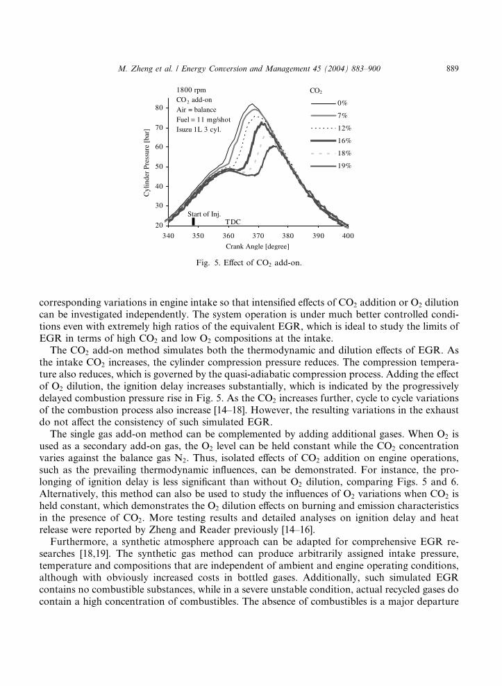
Fig. 5. Effect of CO2 add-on.
M. Zheng et al. / Energy Conversion and Management 45 (2004) 883–900 889
corresponding variations in engine intake so that intensified effects of CO2 addition or O2 dilutioncan be investigated independently. The system operation is under much better controlled condi-tions even with extremely high ratios of the equivalent EGR, which is ideal to study the limits ofEGR in terms of high CO2 and low O2 compositions at the intake.
The CO2 add-on method simulates both the thermodynamic and dilution effects of EGR. Asthe intake CO2 increases, the cylinder compression pressure reduces. The compression tempera-ture also reduces, which is governed by the quasi-adiabatic compression process. Adding the effectof O2 dilution, the ignition delay increases substantially, which is indicated by the progressivelydelayed combustion pressure rise in Fig. 5. As the CO2 increases further, cycle to cycle variationsof the combustion process also increase [14–18]. However, the resulting variations in the exhaustdo not affect the consistency of such simulated EGR.
The single gas add-on method can be complemented by adding additional gases. When O2 isused as a secondary add-on gas, the O2 level can be held constant while the CO2 concentrationvaries against the balance gas N2. Thus, isolated effects of CO2 addition on engine operations,such as the prevailing thermodynamic influences, can be demonstrated. For instance, the pro-longing of ignition delay is less significant than without O2 dilution, comparing Figs. 5 and 6.Alternatively, this method can also be used to study the influences of O2 variations when CO2 isheld constant, which demonstrates the O2 dilution effects on burning and emission characteristicsin the presence of CO2. More testing results and detailed analyses on ignition delay and heatrelease were reported by Zheng and Reader previously [14–16].
Furthermore, a synthetic atmosphere approach can be adapted for comprehensive EGR re-searches [18,19]. The synthetic gas method can produce arbitrarily assigned intake pressure,temperature and compositions that are independent of ambient and engine operating conditions,although with obviously increased costs in bottled gases. Additionally, such simulated EGRcontains no combustible substances, while in a severe unstable condition, actual recycled gases docontain a high concentration of combustibles. The absence of combustibles is a major departure

20
30
40
50
60
70
80
340 350 360 370 380 390 400Crang Angle [degree]
Cyl
inde
r Pr
essu
re [
bar]
0%
7%
14%
24%
28%
CO2 1800 rpmAir+O2 +CO2
O2 = 21%N2 = balanceFuel = 11 mg/shotIsuzu 1L 3cyl.
TDCStart of Inj.
Fig. 6. Effect of CO2 addition with constant O2.
890 M. Zheng et al. / Energy Conversion and Management 45 (2004) 883–900
from actual EGR systems, which, however, helps to operate the engine stably with extremely highextent of CO2 addition and O2 dilution.
A synthetic atmosphere engine test rig is shown in Fig. 7 [18], which is capable of utilizing anumber of inert gases to study extreme operating conditions of EGR. Among the inert gases used,argon has the highest specific heat ratio and is immune from oxidation or dissociation dur-ing combustion. In contrary, carbon dioxide has the lowest specific heat ratio and is likely todissociate into lighter molecules under high temperatures. Argon can be used to compensate the
Fig. 7. Synthetic atmosphere method.

Fig. 8. Non-dimensional power of synthetic atmosphere Diesel engine.
M. Zheng et al. / Energy Conversion and Management 45 (2004) 883–900 891
thermodynamic property changes produced by CO2. Nitrogen gas has similar thermodynamicproperties to air and may be oxidized under high temperatures to generate oxides of nitrogen.
By studying the isolated influences of each inert gas, the mechanisms of EGR on engine ope-ration and emission control can be quantified. This is part of the on going researches at theauthors� laboratories. However, any results obtained from simulated EGR should be verified withwater vapor addition and eventually with actual EGR tests. The consecutive influences between aprevious cycle and a current cycle must be included.
Extensive experiments indicated that synthesized EGR allows extremely higher ratios of EGRthan actual EGR allows [15,19]. Fig. 8 shows the power curves obtained from the test rig whenhigh CO2 is applied, which operation cannot be produced by actual EGR. The results indicatethat power loss alone may tolerate high ratios of EGR.
3. EGR versus NOx
Diesel exhaust contains CO2, H2O, N2 and O2 in thermodynamically significant quantities andCO, THC, NOx and soot in thermodynamically insignificant but environmentally harmfulquantities. In modern Diesel engines, the combination of the former quantities normally comprisemore than 99% of the exhaust, while the latter combination, the pollutants, accounts for less than1% in quantity. Thus, the challenge is to minimize the pollutants by manipulating the thermo-dynamic properties and the oxygen concentration of the cylinder charge whilst keeping minimumdegradations in power and efficiency, which is the principal reason to apply Diesel EGR.
The load levels of a Diesel engine affect the exhaust composition and temperature significantly,which is in stark contrast to exhausts from stoichiometric burning engines that largely remainconstant irrespective of load variations. Notably, load levels are adjusted by fueling rate in Dieselengines but by air–fuel mixture charging rate in SI engines. Thus, exhaust oxygen concentrationsof Diesel engines vary significantly with engine load. In contrary, only a trace of oxygen remains

892 M. Zheng et al. / Energy Conversion and Management 45 (2004) 883–900
in the exhaust of stoichiometric burning engines. Without applying EGR, energy efficient Dieselengines normally produce an exhaust that contains oxygen from 5% at full load to 20% duringidling. As the excessiveness of exhaust oxygen diminishes with the increase in engine load, thespecific heat of the exhaust rises because of the increase in the combustion product CO2.
Thus, the effectiveness of NOx reduction by EGR also varies with load. The heat capacity of thecylinder charge increases with the increase in CO2 that is brought in by EGR. The flame tem-perature and, thus, the maximum temperature of the working fluid will be lowered with the in-crease in CO2. Test results indicate that high ratios of EGR need to be applied at low load but lowratios of EGR are sufficient for high load, Figs. 9 and 10. When operating at lower loads, Dieselengines generally tolerate a higher EGR ratio because the exhaust contains a high concentrationof O2 and low concentrations of combustion products CO2 and H2O. At high loads, however, theexhaust oxygen becomes scarce and inert constituents become dominating.
If hot exhaust is directly recirculated, the cylinder charge temperature will be afloat with theinflux of the EGR heat, especially at high loads, which will raise the working fluid temperature.Test results demonstrated that cooled EGR reduces NOx more effectively than hot EGR [2]. Thetests shown in Fig. 9 were conducted with synthetic atmosphere as intake, which was equivalent tothoroughly cooled EGR. The intake mixture temperature was maintained at 30 �C, referring Fig.7. The synthetic EGR rate follows the CO2 definition discussed previously. The test results in Fig.10 were obtained with laboratory enhanced EGR cooling that kept the EGR cooler outlet tem-perature below 80 �C. In the same figure, a comparison was also shown with hot EGR, and it wasapparent the NOx reduction was less effective.
As load increases, Diesel engines tend to generate more smoke because of reduced access tooxygen. Employing EGR, although effective to reduce NOx, further aggravates the scenario, i.e.the prevailing NOx and PM trade-off, as shown in Fig. 11 [10,11,19,20]. Testing results indicatethat low load operations are commensurate with high rates of EGR, while high loads indicate lowor no EGR [2,10,13]. More importantly, the trend of increased PM formation commonly hinders
Fig. 9. NOx reduction versus synthetic EGR rate.

0
200
400
600
800
1000
0% 5% 10% 15% 20% 25% 30%
EGR Rate
Exh
aust
NO
x [p
pm]
Speed= 2100 rpmBMEP= 9 bar
Hot Raw EGR
EnhancedCooled EGR
Fig. 10. Comparison between cooled and hot EGR.
0
200
400
600
800
1000
0 5 10
Opacity(%)
NO
X(p
pm
)
NOx v/s Opacity 0% Load
Opacity 25% Load
Opacity 50% Load
Opacity 75%Load
0%
5%
10%
15%
20%25%
NOx v/s
NOx v/s
NOx v/s
Fig. 11. Trade-off between exhaust NOx and opacity (smoke) when hot EGR is applied.
M. Zheng et al. / Energy Conversion and Management 45 (2004) 883–900 893
the application of EGR at full loads. However, since NOx generation is severe at full loads,extended fuel injection retarding could be implemented in lieu of EGR [11].
4. Control of EGR
An ideal control strategy should collate EGR rate with NOx generation rate transiently. Shortof viable fast response lean NOx sensors, the resort is to use look-up tables to command theEGR valve opening. The look-up tables comprise a primary command table that is based onengine speed and fueling rate (engine load) and a number of modification tables that refer to the

894 M. Zheng et al. / Energy Conversion and Management 45 (2004) 883–900
operating parameters, such as engine block temperature, boost pressure, injection timing etc. Suchstatic tables are calibrated by the engine manufacturers and reside in the engine control module(ECM).
The impact of EGR on engine operation is similar to turbocharging, both of them affecting theequilibrium states of the entire system. Although appropriate control strategies are capable ofsetting up consistent EGR operations initially, any drifts in engine operation will affect the initialsetup when EGR feedback is not available. In order to achieve feedback control, a commonpractice is to estimate the EGR rate via measuring the fresh intake air with a mass air flow (MAF)sensor. By assuming a mass flow rate of the cylinder charge, the mass flow rate of EGR could bedetermined by mass conservation on a steady operating condition:
_mmEGR ¼ _mmInt � _mmMAF
However, the estimation on the mass flow of the cylinder charge is hindered by a number oftransient operating parameters that include EGR temperature, engine block temperature, after-cooler temperature and boost pressure, while most of these parameters are not monitored by theECM. Additionally, if a variable geometry turbine (VGT) is employed to ensure sufficient EGR,by raising the turbine upstream pressure (P3 in Fig. 3), adjustment of the nozzle areas of the VGTis commonly based on static look-up tables even when the pressure and temperature of theexhaust drift significantly [8,12,13].
Furthermore, a sufficient EGR control needs real time EGR rate and combustion qualitymonitoring, but viable sensor technologies associated with lean burn systems are yet to be de-veloped. For instance, although the boost pressure is normally monitored by an engine ECM, theturbine upstream conditions are commonly not monitored. Without sufficient feedback control,the setup of EGR has to compensate any discrepancies of implementation. Consequently, themaximum EGR ratios in use are generally lower than the maximum allowable EGR that isoptimized on well controlled conditions. In general, the EGR operation effects engine operatingstabilities through the following parameters:
• EGR valve opening,• EGR loop differential pressure,• EGR cooler cooling efficiency,• in cylinder combustion efficiency,• exhaust and intake temperatures.
The above parameters directly affect the quantity and/or quality of EGR that, in turn, affectsthe equilibrium states of engine operation. For instance, the characteristics of in-cylinder fuelburning affect the exhaust temperature that, in turn, affects the exhaust backpressure. Thebackpressure directly affects the rate of EGR that again affects the in-cylinder burning processes.Additionally, the functioning of the following sub-systems also affects EGR through their influ-ences on exhaust backpressure:
• turbocharging,• exhaust brake,• exhaust aftertreatment systems.

M. Zheng et al. / Energy Conversion and Management 45 (2004) 883–900 895
5. Treatment of EGR
Because of the vitality of EGR in NOx reduction, it is prudent to explore the applicable limits ofEGR. Notably, heavy uses of EGR could degrade the energy efficiency and mechanical durabilityof the engine [10]. Besides, excessive uses of EGR also cause operational instabilities that furtheraggravate the engine efficiency and durability [18]. However, such instabilities can be reduced bymodifying the EGR stream thermally and/or chemically, i.e. through EGR treatments [17].
5.1. EGR cooling
EGR cooling increases the density and, therefore, the mass flow rate of the intake charge, whichis as important as boost inter-cooling. It is known that the inter-cooler plays an important role inimproving engine performances and emissions. In order to prevent fouling, the recirculated ex-haust is normally introduced downstream of the inter-cooler, as shown in Fig. 4. Without inter-cooling, the boost temperature can reach 80 �C frequently and over 160 �C occasionally formoderately turbocharged engines. Effective inter-coolers, which use ambient air as the coolingmedium (air cooled), can bring down the boost temperature to only 5–20 �C higher than theambient. Obviously, if the engine jacket coolant, which has a temperature of 85–95 �C commonly,is used as the cooling medium (water cooled), the inter-cooling would be less effective.
In case hot EGR is applied in conjunction with boost inter-cooling, no matter how effective theair-cooler is, the intake air will be heated by the recirculated exhaust that sets back the intakecooling. Thus, it is imperative to implement sufficient cooling on the EGR. Normally, the enginejacket coolant is used as the cooling medium to remove heat from the EGR stream. Such liquidEGR coolers are compact and easy to install. A cooled exhaust temperature approximating 120 �Cis preferred [8].
Furthermore, it is more effective to reduce NOx by cooled EGR, which shares the same scenariowith boost inter-cooling. A comparison between hot and cooled EGR is shown in Fig. 12. Thetesting engine has been described by Zheng et al. [17] and Patel [20] previously. A custom built
0
200
400
600
800
1000
0% 5% 10% 15% 20% 25% 30%
EGR Rate
Exh
au
st N
Ox
[pp
m]
Speed = 2100 rpmBMEP = 9 bar
Hot Raw EGR
EnhancedCooled EGR
Fig. 12. The effect of EGR cooling on NOx production.

896 M. Zheng et al. / Energy Conversion and Management 45 (2004) 883–900
large EGR cooler using tap water was used to maintain the EGR cooler outlet temperature below120 �C. During the tests, the EGR cooler commonly kept the recycled gas below 70 �C.
EGR cooling also has the potential to stabilize the engine operation by holding the temperatureof the recirculated exhaust, a grounding effect in the feedback loop, because the exhaust tem-perature variations are isolated from the engine intake. An EGR cooler also inserts a plenum inthe EGR loop that helps pressure pulsation damping, which effect is also enhanced by the flowrestrictions associated with the EGR plumbing [21].
5.2. EGR oxidation
Although excessive EGR causes dramatic NOx reduction, the engine operation also approacheszones with higher cyclic variations. Such instabilities are largely associated with prolonged igni-tion delay and incomplete combustion, which are caused by increased CO2 and decreased O2 inthe engine intake [14,18]. The deterioration in combustion efficiency results in fluctuations in thecombustion products that may escalate the consecutive cyclic variations of the cylinder charge interms of temperature, pressure and composition [17–19].
In a conventional EGR system, the EGR flow rate is adjusted with an EGR valve, while theEGR temperature is preferably reduced with an EGR cooler. However, the constituents of theEGR stream are generally left intact. Uncontrolled EGR components, such as combustibles, arecommonly introduced to the engine combustion chamber. The approach is to eliminate the in-fluences of recycled combustibles on such instabilities, by applying oxidation with a catalyst in thehigh pressure EGR loop [18]. The elimination of recycled combustibles showed significant effectson stabilizing the cyclic variations, so that the EGR applicable limits are effectively extended. Theattainability of low NOx emissions with the catalytically oxidized EGR is shown in Fig. 13.
From medium to high load operations, the exhaust temperatures are above 350 �C for the testengine. At such temperature levels, a satisfactory conversion rate of CO and reactive HC can beobtained reliably with modern catalyst technologies [22,23]. Since high load operation was tar-geted in the present work, the oxidation catalyst showed over 90% efficiency in destroying therecycled combustibles.
20%
40%
60%
80%
100%
0% 10% 20% 30%
EGR Rate
NO
x E
mis
sion
Treated EGR
Raw EGR
Speed = 2100 rpmBMEP =9 bar
Fig. 13. The effect of oxidation treated EGR.

Fig. 14. The layout of an oxidation catalytic EGR operation.
M. Zheng et al. / Energy Conversion and Management 45 (2004) 883–900 897
The oxidation catalytic converter (Fig. 14) oxidizes unburned combustibles into CO2 and H2O.Although the fuel in the EGR stream was sacrificed by oxidation, it provided a necessary safetymargin to run aggressive EGR stably. This is critical when considering the inconsistencies inpractical operations. Fig. 15 indicates that the oxidized EGR extended the limit of EGR.
5.3. EGR fuel reforming
Diesel exhaust temperatures normally range from 120 to 720 �C for non-turbocharged systemsand 100 to 600 �C for turbocharged systems. The exhaust oxygen concentration is in the rangefrom 19% to 4% for naturally aspirated engines and 19% to 7% for turbocharged engines, fromidle to full load. Because of the significant amounts of surplus oxygen in the exhaust, a method isproposed here to suppress PM production with EGR by fuel reforming in the EGR loop. The heatof the exhaust can be utilized simultaneously. In comparison, exhausts from stoichiometriccombustion engines are not suitable for fuel reforming because of the obvious lack of oxygen. Aresearch has been planned at the authors� laboratory to incorporate a catalytic rich combustor
0
20
40
60
80
180 240 300 360 420 480 540
Crank Angle [degree]
Cyl
inde
r P
ress
ure
[bar
]
Raw EGR 16%, NOx 610 ppmCooled EGR 24%, NOx 320 ppm
Cooled and Oxidized EGR 27%,NOx280 ppmZero EGR, NOx870 ppm
Stable Limiting EGRSpeed = 2100 rpmBMEP = 9bar
Fig. 15. Cylinder pressure traces of limiting stable EGR operations.
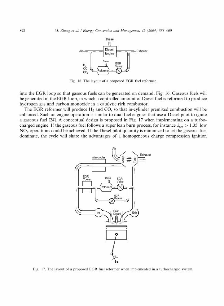
Fig. 16. The layout of a proposed EGR fuel reformer.
898 M. Zheng et al. / Energy Conversion and Management 45 (2004) 883–900
into the EGR loop so that gaseous fuels can be generated on demand, Fig. 16. Gaseous fuels willbe generated in the EGR loop, in which a controlled amount of Diesel fuel is reformed to producehydrogen gas and carbon monoxide in a catalytic rich combustor.
The EGR reformer will produce H2 and CO, so that in-cylinder premixed combustion will beenhanced. Such an engine operation is similar to dual fuel engines that use a Diesel pilot to ignitea gaseous fuel [24]. A conceptual design is proposed in Fig. 17 when implementing on a turbo-charged engine. If the gaseous fuel follows a super lean burn process, for instance kgas > 1:35, lowNOx operations could be achieved. If the Diesel pilot quantity is minimized to let the gaseous fueldominate, the cycle will share the advantages of a homogeneous charge compression ignition
Fig. 17. The layout of a proposed EGR fuel reformer when implemented in a turbocharged system.

M. Zheng et al. / Energy Conversion and Management 45 (2004) 883–900 899
(HCCI) engine system. HCCI systems improve fuel economy through nearly instantaneouscombustion of a super lean homogeneous fuel/air mixture, which produces very low NOx andparticulate matter (PM) emissions. However, breakthroughs are needed to enhance the ignitionconsistency and to expand the load levels in order to make HCCI operations practical.
6. Final comments
Diesel exhaust contains sulfuric salts and other abrasive and corrosive substances. It has beenargued whether EGR should be applied to Diesel engines because of the increased piston-cylinderwearing [25]. Heavy uses of EGR could also deteriorate the energy efficiency, operational stabilityand PM generation of the engine. However, the concern over increased wearing and deterioratedperformance has soon given way to stringent emission regulations. In stark contrast, the currentconcern is on how aggressively EGR should be applied to all speeds and all loads, although EGRincreased wearing continues to be a problem affecting engine durability and performances.
To date, EGR is still the most viable technique that can reduce NOx dramatically. Energyefficient aftertreatment systems dealing with NOx and PM simultaneously are still in the earlydevelopment stages. The inability of available catalytic aftertreatment technologies furtherencourages aggressive uses of EGR.
References
[1] Borman GL, Gagland KW. Combustion engineering. WCB/McGraw-Hill; 1998.
[2] Zelenka P, Aufinger H, Reczek W, Catellieri W. Cooled EGR––a key technology for future efficient HD Diesels.
SAE paper 980190, 1998.
[3] Kreso AM, Johnson JH, Gratz LD, Bagley ST, Leddy DG. A study of the effects of exhaust gas recirculation on
heavy-duty Diesel engine emissions. SAE paper 981422, 1988.
[4] Heywood JB. Internal combustion engine fundamentals. McGraw-Hill Inc.; 1988.
[5] Borissov A, McCoy JJ. Supersonic injection of gaseous fuel described as possible solution for emission from large-
bore gas engines. ASME ICE, vol. 38-488, 2002.
[6] Akihama K, Takatori Y, Inagaki K, Sasaki S, Dean AM. Mechanism of the smokeless rich Diesel combustion by
reducing temperature. SAE paper 2001-01-0655, 2001.
[7] Kimura S, Aoki O, Kitahara Y, Aiyoshizawa E. Ultra-clean combustion technology combining a low-temperature
and premixed combustion concept for meeting future emission standard. SAE paper 2001-01-0200, 2001.
[8] Ishida A, Nishimura A, Uranishi M, Kihara R, Nakamura A, Newman P, et al. Development of ECOS-DDF
natural gas engine for medium duty trucks––exhaust gas emission reduction against base Diesel engine. JSAE
paper 20005001, 2000.
[9] Hultqvist A, Engdar U, Johansson B, Klingmann J. Reacting boundary layers in a homogeneous charge
compression ignition (HCCI) engine. SAE paper 2001-01-1032, 2001.
[10] Machacon H, Shiga S, Karasawa T, Nakamura H. Simultaneous reduction of soot and NOx by intake gas
variation. 6th International Symposium on Marine Engineering, 2000.
[11] Murayama T, Zheng M, Chikahisa T, Oh Y, Fujiwara Y, Tosaka S, et al. Simultaneous reductions of smoke and
NOx from a DI Diesel engine with EGR and dimethyl carbonate. SAE Transactions 952518, 1995.
[12] Tomazic D, Pfeifer A. Cooled EGR––a must or an option for 2002/04. SAE paper 2002-01-0962, 2002.
[13] Hawley JG, Wallace FJ, Cox A, Horrocks RW, Bird GL. Reduction of steady-state NOx levels from an automotive
Diesel engine using optimized VGT/EGR schedules. SAE paper 1999-01-0835, 1999.

900 M. Zheng et al. / Energy Conversion and Management 45 (2004) 883–900
[14] Zheng M, Reader GT. Preliminary investigation of cycle to cycle variations in a nonair-breathing Diesel engine.
J Energy Resour Technol 1995;117:24–8.
[15] Zheng M, Reader GT. An experimental analysis of EGR on operational stabilities of Diesel engines. ASME ICE,
vol. 36-1, 1993. p. 101–106B.
[16] Zheng M, Reader GT, Galinsky G, Potter I, Gustafson RW. Ignition delay and pressure–time characteristics in a
Diesel engine using carbon dioxide and argon enriched oxidants. 1993 ETCE (ASME), February 1993.
[17] Zheng M, Irick DK, Hodgson J. Stabilizing excessive EGR with an oxidation catalyst on a modern Diesel engine.
ASME ICE, vol. 38, 2002-ICE-455.
[18] Zheng M, Reader GT. An experimental analysis of EGR on operational stabilities of Diesel engines. ASME ICE,
vol. 36-1, 2001.
[19] Bowen C. An experimental investigation into the use of exhaust gas recirculation for Diesel engine NOx control.
PhD Thesis, University of Calgary, 1998.
[20] Patel KP. Study of NOx and loading of a soot filter versus EGR for a 2.4L Diesel engine. MS Thesis, University of
Tennessee, 2001.
[21] Benson RS. In: The thermodynamics and gas dynamics of internal-combustion engines, vol. 1. Oxford: Clarendon
Press; 1986.
[22] Farrauto RJ, Voss KE. Monolithic Diesel oxidation catalysts. Appl Catal B: Environ 1996;10:29–51.
[23] Mogi H, Tajima K, Hosoya M, Shimoda M. The reduction of Diesel engine emissions by using the oxidation
catalysts on Japan Diesel 13 mode cycle. SAE paper 1999-01-047.
[24] Zheng M, Mirsh E, Klopp W, Ulan D, Pardell M, Newman P, et al. Development of a compact reverse-flow
catalytic converter for Diesel dual fuel LEV. SAE paper 1999-01-3558.
[25] Ishiki K, Oshida S, Takiguchi M, Urabe M. A study of abnormal wear in power cylinder of Diesel engine with
EGR––wear mechanism of soot contaminated in lubricating oil. SAE paper 2000-01-0925.