Embed Size (px)
Citation preview
Turk J Elec Eng & Comp Sci
(2015) 23: 1479 – 1488
c⃝ TUBITAK
doi:10.3906/elk-1303-48
Turkish Journal of Electrical Engineering & Computer Sciences
http :// journa l s . tub i tak .gov . t r/e lektr ik/
Research Article
Dielectric loaded TEM horn-fed ridged horn antenna design for ultrawideband
ground-penetrating impulse radar
Ahmet Serdar TURK∗, Ahmet Kenan KESKIN, Mustafa Dagcan SENTURKDepartment of Electronics and Telecommunication Engineering, Yıldız Technical University,
Esenler, Istanbul, Turkey
Received: 08.03.2013 • Accepted/Published Online: 22.09.2013 • Printed: 28.08.2015
Abstract: A modified double-ridged horn structure is proposed to obtain ultrawideband antenna characteristics over a
bandwidth ratio of greater than 40:1 for impulse radar systems. The Vivaldi-shaped TEM horn feeder has been designed
to extend the lower cut-off frequency and the partial dielectric loading technique using a small lens inward while the
aperture has been implemented to enhance the gain of the standard double-ridged horn antenna without changing the
physical dimensions. The starting frequency of the antenna operation band is lowered from 800 MHz to 400 MHz.
Moreover, approximately 5 dB gain increment level is achieved from 4 to 10 GHz. It is shown that proper combination
of the partial dielectric loaded TEM and ridged horn antennas can be suitable for multiband ground-penetrating radar
operations that provide high resolution imaging at different depths. The antenna gain and input reflection performance
measurements are presented with comparisons in both the frequency and time domains.
Key words: Ultrawideband antennas, dielectric loaded TEM horn, double-ridged horn, ground-penetrating radar,
impulse radiator
1. Introduction
Ultrawideband (UWB) technologies are used for radio frequency (RF) wireless networks, high-speed communica-
tion, RF jammers, and high-resolution radar systems [1]. They can employ short-time impulse, wideband noise,
or stepped frequency signal radiation methods with a very broad band of operation from hundreds of megahertz
up to millimeter waves. The UWB radar operation yields crucial advantages for small object detection, adaptive
range resolution, antijamming, and improved target imaging performances.
Over the last several decades, ground-penetrating radar (GPR) has been an important near-zone radar
technology for buried object detection and subsurface imaging. It has a very broad range of applications,
including geophysics, civil engineering, archaeology, transportation, nondestructive testing, mine detection, and
remote sensing (i.e. through-wall imaging) [2]. In GPR systems, an electromagnetic wave is transmitted into
the ground and the identification of buried targets or sublayers is obtained by examining the backscattered
field. The higher frequencies and wider operational bands are required for better quality of subsurface image
and range resolution, whereas the lower frequencies must be preferred for deeper analysis due to the sharply
increasing soil attenuation with frequency. Thus, UWB GPR systems that transmit short impulse signals are
usually proposed [3]. The impulse durations usually vary between nanoseconds to hundreds of picoseconds,
which corresponds to a broad spectrum from 100 MHz to 10 GHz, depending on the applications. For example,
∗Correspondence: [email protected]
1479

TURK et al./Turk J Elec Eng & Comp Sci
10–200 MHz GPRs are usually used for geophysical surveys and GPRs of 400 MHz to 2 GHz are more popular
in the market for utility detection and road inspection. It can be extended up to 15 GHz for multiband GPR
systems, which can use microwave tomography methods for high-resolution subsurface imaging.
The convenient design of UWB antennas is a major issue for the GPR system performance. The GPR
antennas must attain high gain, narrow beam, low side lobe, and input reflection level characteristics over the
wide band to reach the powerful and adequately shaped impulse radiation [2]. Within this scope, loaded dipoles,
bow-ties, butterflies, and spirals are typical planar antennas adoptable for hand-held systems due to their light-
weight structures [3,4]. However, horn antenna types are more popular for vehicle-mounted GPR systems.
Usually TEM horns are employed for impulse GPRs due to better low- and mid-band gain characteristics
[5], and ridged horns are preferred for stepped-frequency GPRs because of high gain over 1 GHz. Dielectric
loading approaches can be useful to make the antenna bands broadened, such as the dielectric wedge antenna
[6]. Another example is the partially dielectric loaded TEM (PDTEM) horn designed by Turk with 20:1 UWB
radiation performances from 500 MHz to 10 GHz [7,8]. Its array version was designed to extend the bandwidth
ratio up to 50:1 [9]. Recently, partially dielectric lens loading was also proposed for gain enhancement of a
standard double-ridged horn antenna [10].
This paper describes a favorable antenna array combination by using the PDTEM horn as a feeding
mechanism of the standard 1–18 GHz double-ridged horn to achieve extended wideband radiation performances
with enhanced gain from 400 MHz up to 15 GHz. The partial dielectric loaded transmission line antenna
method (PLTLM) is used for fast analysis and appropriate design of the PDTEM horn feeder. The results
of the UWB gain and voltage standing wave ratio (VSWR) measurements of the novel modified ridged horn
structure are presented and compared with same-sized standard dual-ridged horn antenna (DRHA). The case
shape, outer sizes, and dielectric structure of the designed antenna are almost the same as in [10]. However, the
main novelty of this study is the use of the Vivaldi-shaped TEM horn feeder mechanism, which is completely
different from both the standard and modified ridged horns in [10] that use TE/TM mode feeding. Hence, the
lower cut-off frequency of the ridged horn in [10] can be extended from 800 MHz to 400 MHz, which is the
major contribution of this study that yields increased gain bandwidth ratio by up to 80%. As a result, the
UWB antenna performances are achieved from 0.4 to 15 GHz (the target gain is over 0 dBi and target VSWR
is less than 3) that corresponds to 40:1 bandwidth ratio.
2. PLTLM analysis of TEM horn feeder
Transmission line methods are suitable for fast analysis of long V-dipole antenna types. Therefore, the PLTLM
can be applied to the dielectric loaded TEM horn structure for preliminary design of the PDTEM horn feeder
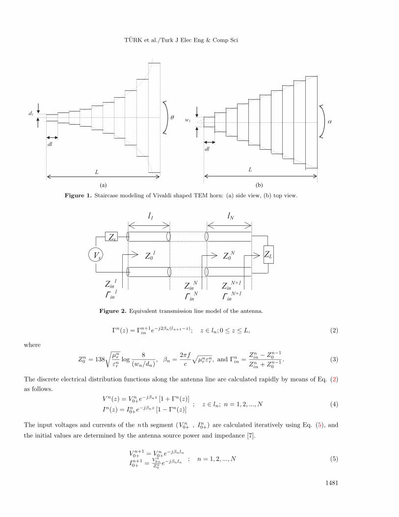
part by using the staircase modeling shown in Figure 1 and described in detail in [7]. Briefly, the 3D TEM horn
antenna geometry is first considered as the composition of N number of locally homogeneous small microstrip
line segments. At the second stage, this structure is reduced to the equivalent transmission line illustrated in
Figure 2 with local characteristic impedance (Zn0 ), propagation constant (βn), and segment size characteristics
(ln), (wn), and (dn). Each line segment has the following input impedance and local reflection coefficient values
defined by Eqs. (1)–(3) [8]:
Znin = Zn0Zn+1in + jZn0 tanβnln
Zn0 + jZn+1in tanβnln
; n = 1, 2, ..., N, (1)
1480
TURK et al./Turk J Elec Eng & Comp Sci
(a)
(b)
θ
dl
d1
L
α
dl
w1
L
Figure 1. Staircase modeling of Vivaldi shaped TEM horn: (a) side view, (b) top view.
Vs
Zs
l1
Zin
1
Γ in
1
Z0
1
Zin
N
Γ in
N
lN
Zin
N+1
Γ in
N+1
ZL Z0
N
Figure 2. Equivalent transmission line model of the antenna.
Γn(z) = Γn+1in e−j2βn(ln+1−z); z ∈ ln; 0 ≤ z ≤ L, (2)
where
Zn0 = 138
√µnrεnr
log8
(wn/dn), βn =
2πf
c
√µnr ε
nr , and Γnin =
Znin − Zn−10
Znin + Zn−10
. (3)
The discrete electrical distribution functions along the antenna line are calculated rapidly by means of Eq. (2)
as follows.
V n(z) = V n0+e−jβnz [1 + Γn(z)]
In(z) = In0+e−jβnz [1− Γn(z)]
; z ∈ ln; n = 1, 2, ..., N (4)
The input voltages and currents of the nth segment (V n0+ , In0+) are calculated iteratively using Eq. (5), and
the initial values are determined by the antenna source power and impedance [7].
V n+10+ = V n0+e
−jβnln
In+10+ =
V n0+
Zn0e−jβnln
; n = 1, 2, ..., N (5)
1481

TURK et al./Turk J Elec Eng & Comp Sci
The far-field calculation procedure of PLTLM is based on the linear current density approximation over the
narrow-angle PDTEM horn antenna wing (YOZ plane cross-section) [7]. In this case, the far-field formulation
given in Eq. (6) can be transformed into the numerical form given in Eq. (7), by means of Eq. (8) as described
below:
A =µ
4π
∫L
Js(y′, z′)
e−ik(r−r′n cosψn)
r(dl sin θ′
a y + dl cos θ′
a z), (6)
E(r, θ, ϕ) ∼=iωµ
4π
L
N
e−ikr
r
N∑n=1
|In|eikr′n cosψn+iξn(sin θ′n
a y + cos θ′n
a z), (7)
where
In = |In| eiξn ,
cosψn =r.r′n
|r| . |r′n|=
x.x′n + y.y′n + z.z′n
r√(x′n)
2 + (y′n)2 + (z′n)
2. (8)
Here, In is the current density of the nth TEM horn line segment at (x′n, y′n, z
′n) coordinates (see [8] for
details). In this way, UWB input reflection level and antenna radiation characteristics of the TEM horn feeder
can be calculated roughly, but much faster than with 3D direct numerical techniques. PLTLM algorithm
has been compared with 3D method of moments solutions for TEM horn analysis and good agreements were
demonstrated in previous papers [7].
3. Modified ridged horn design with PDTEM horn feeder
The Vivaldi-shaped TEM horn feeder antenna can be characterized basically by the L ,d , α , and θ parameters,
which are illustrated in Figure 1. The geometry is arranged to match the antenna aperture impedance to the 50
Ω source by adopting the antenna line segment characteristic impedances (see Figure 3). For this aim, the local
widths, heights, and dielectric constants of these antenna segments are determined according to Eq. (2). This
technique is useful to transform and match the aperture impedance into the antenna feeder line at sufficiently
high frequency bands, which correspond to the electrically long antenna case. For lower frequencies where the
antenna line is shorter than the wavelength, the TEM horn aperture is loaded with a resistive sheet to improve
the low-band VSWR levels. The sheet resistivity should be optimized at about 200 Ω to avoid remarkable gain
degradation at high-frequency regions due to high sheet conductivity [8].
0 5 10 15 20 250
50
100
150
Length (cm)
)o
Z( ecn
ade
pmi citsiretc
ara
hC
PDTEM-RHA
TEMRHA
Figure 3. Segment characteristic impedances along the TEMRHA feeder antenna line.
1482

TURK et al./Turk J Elec Eng & Comp Sci
The partial dielectric-loading configuration shown in Figure 4 and described in the Table is proposed to
enhance the antenna gain and input reflection performances over the wideband. The dielectric profile material
is Teflon. The grating wires are used near the antenna aperture to prevent the filtering of high-frequency
waveguide modes’ radiation of the ridged horn structure (see Figure 5).
Figure 4. PDTEM horn feeder geometry: (a) side view, (b) side and front views of dielectric profile.
(a) (b)
Figure 5. The 3D view of the PDTEM-RHA geometry: (a) illustration, (b) photo.
Table. PDTEM horn feeder and modified DRHA designs.
Figure Model Physical descriptions
4PDTEM
α= 20, θ = f(l) ∈(0–120), d= 0.4 cm, L= 25 cm
horn feederDielectric profile: εr = 2.1 (Teflon), a1= 6 cm, a2= 10 cm,b1= 3 cm,w1= 10 cm
5DRHA Aperture width (W ) = 24.4 cm, aperture height(reference, 1–18 GHz) (H) = 15.9 cm, outer depth (D) = 27.9 cm
5* PDTEM-RHA Same physical sizes as DRHA (with PDTEM horn feeder)
*Figure 5 is modified illustration of DRHA (with PDTEM horn feeder).
1483

TURK et al./Turk J Elec Eng & Comp Sci
The modified configuration of the DRHA with PDTEM horn feeder (PDTEM-RHA) illustrated in Figure
5 and specified in the Table has been designed. The main motivation of this novel design is to combine
the standard double-ridged horn with PDTEM horn antenna to extend the operational gain band to lower
frequencies. Furthermore, it is also aimed to enhance the mid-band gain of the standard DRHA by the small
dielectric lens of the PDTEM feeder.
4. Results and discussion
The antenna gain, input reflection level, and radiation pattern performances of the designed PDTEM-RHA are
measured by a Rohde-Schwarz ZVL13 network analyzer between 10 MHz and 15 GHz and compared with the
reference 1–18 GHz standard DRHA as described in the Table. The antenna gain and radiation characteristics
were measured at 5 m in distance in our microwave laboratory using Eccosorb VHP-12 type wideband (500
MHz to 24 GHz) pyramidal absorber layers to perform sufficiently reliable indoor pattern measurements. The
antenna impulse radiation gains are also calculated for different operational GPR bands by using the IFFT
of the measurements. Moreover, one T/R pair of the PDTEM-RHA is mounted to the Geozondas GZ6E-15
GHz impulse GPR system and preliminary test results of collected B-scan data are plotted for buried object
detection and through-wall imaging scenarios.
The UWB antenna gain measurement results of the PDTEM-RHA and calibrated DRHA are plotted
in Figure 6a. The standard DRHA, which has same aperture as the PDTEM-RHA, shows wide band gain
characteristics from 800 MHz (limited by waveguide cut-off frequency) to 15 GHz. However, the PDTEM-RHA
attains a twice-broadened gain bandwidth ratio because of extended lower band performance, as an advantage
of use of the TEM horn feeder (Figure 6b). The gain bandwidth ratio of the antenna is about 40:1 (400 MHz
to 15 GHz). Moreover, the PDTEM-RHA yields almost 5 dB more gain than the standard DRHA over a wide
mid-band (4–10 GHz) that can be very useful for near-surface GPR and UWB communication devices [1–3].
Nevertheless, due to the complicacy of many propagating modes at such a hyperwide band operation, a few dB
gain degradations (relatively to the DRHA) are observed at three local narrow bands (around 1.5 GHz, 11.5
GHz, and 14 GHz frequencies). In any case, the overall impulse radiation performance of the PDTEM-RHA is
better than that of the DRHA at all GPR operation bands of (from 10 MHz to) 750 MHz, 1 GHz, 1.5 GHz, 2
GHz, 3 GHz, 5 GHz, 8 GHz, and 15 GHz, as presented in Figure 6c.
The antenna input reflection parameter is also highly important for the GPR performance. Mismatching
with the wideband pulse generator should be avoided. Otherwise, the radiated impulse signal shape will be
corrupted due to the ringing. In this case, the GPR system clutter level increases, and hence recognition of the
scattered signal from the buried object is complicated. Figure 7 shows that the designed PDTEM-RHA can
reach sufficiently low VSWR values, which are less than 2.8 with 1.8 band average, from 300 MHz to 15 GHz.
The radiation pattern measurements are shown in Figure 8. The half-power beam widths of the PDTEM-
RHA are 30% narrower than those of the DRHA until 12 GHz. Some side lobes may occur at high frequencies,
but their levels are limited to –15 dB to the main lobe and they can be suppressed more by the T/R antenna
shielding box of GPR head systems.
The test setup photo of the UWB impulse GPR using the PDTEM-RHA is given in Figure 9. The target
detection performances for buried objects and through-wall imaging scenarios are presented as B-scan plots
in Figures 10a and 10b, respectively. The hyperbolic detection responses of two metal objects buried under
soil at different depths and a moving human body behind a concrete wall are demonstrated in Figure 10 for
performance comparison of GPR heads with the designed PDTEM-RHA and standard DRHA. It is seen in
1484

TURK et al./Turk J Elec Eng & Comp Sci
0 3 6 9 12 15–20
–15
–10
–5
0
5
10
15
20
Frequency (GHz)
Gai
n (d
Bi)
DRHAPDTEM–RHA
(a)
200 400 600 800–20
–15
–10
–5
0
5
10
Frequency (MHz)
Ant
enna
gai
n (d
Bi)
DRHAPDTEM–RHA
(b)
Inp
uls
e r
esp
on
se (
S2
1)
(c)
Figure 6. Gain performance measurements of the PDTEM-RHA: (a) ultrawideband antenna gain (with reference
DRHA), (b) low-band antenna gain (with reference DRHA), (c) time domain transformations of S21 measurements for
different GPR bands (— standard DRHA; designed PDTEM-RHA).
0 3 6 9 12 151
2
3
4
5
6
7
Frequency (GHz)
VSW
R
DRHAPDTEM-RHA
Figure 7. VSWR performance measurements of the PDTEM-RHA (with ref. DRHA).
1485

TURK et al./Turk J Elec Eng & Comp Sci
20
10
0
-10
-200
30
60
90
120
150
180
20
10
0
-10
-200
30
60
90
120
150
180
20
10
0
-10
-200
30
60
90
120
150
180
20
10
0
-10
-200
30
60
90
120
150
180
20
10
0
-10
-200
30
60
90
120
150
180
3 GHz
20
10
0
-10
-20
30
60
90
120
150
180
20
10
0
-10
-200
30
60
90
120
150
180
500 MHz
1 GHz 1.5 GHz
5 GHz
7.5 GHz 10 GHz
20
10
0
-10
-200
30
60
90
120
150
18012 GHz
750 MHz
20
10
0
-10
-200
30
6
90
120
150
180
15 GHz
20
10
0
-10
-200
30
60
90
120
150
180
PDTEM-RHA
DRHA
PDTEM-RHA
DRHA
PDTEM-RHA
DRHA
PDTEM-RHA
DRHA
PDTEM-RHA
DRHA
PDTEM-RHA
DRHA
PDTEM-RHA
DRHA
PDTEM-RHA
DRHA
PDTEM-RHA
DRHA
PDTEM-RHA
DRHA
Figure 8. Radiation pattern measurements of the PDTEM-RHA (with reference DRHA).
1486

TURK et al./Turk J Elec Eng & Comp Sci
Figure 9. Test and measurement setup of 15 GHz impulse GPR system.
Dep
th (
cm)
0
5
10
15
20
25
30
35
40
45 –200
–150
–100
–50
0
50
100
150
Dep
th (
cm)
0
5
10
15
20
25
30
35
40
45
0
5
10
15
20
25
30
35
40
45 –200
–150
–100
–50
0
50
100
150
(a)
Dep
th (
cm)
0
10
20
30
40
50
60
Dep
th (
cm)
0
10
20
30
40
50
60
–5
–4
–3
–2
–1
0
1
2
3
4
5(b)
1 2
3 4
Figure 10. B-scan subsurface imaging results of the 15 GHz impulse GPR: (a) detection of the metal plates (10 × 10
cm) buried at 5 cm and 20 cm depths, 1- performance of PDTEM-RHA, 2- performance of DRHA; (b) through-wall
imaging of a human body moving behind a 30 cm concrete wall, 3- performance of PDTEM-RHA, 4- performance of
DRHA.1487

TURK et al./Turk J Elec Eng & Comp Sci
Figure 10a that PDTEM-RHA and DRHA have similar detection performances for shallow buried objects due
to the low attenuation of dry soil at high frequency regions. However, DRHA performance degrades sharply in
the case of lossy mediums at high frequencies, such as the concrete wall scenario in Figure 10b.
5. Conclusion
In this work, the standard DRHA was modified by PDTEM horn feeding mechanism for impulse radar,
multiband GPR, and ultrawideband communication systems. The partial dielectric loaded transmission line
method is applied for fast predesign of the PDTEM horn feeder. The antenna gain, input reflection, and radiation
pattern measurements of the PDTEM-RHA are exhibited at the 0.01–15 GHz frequency band with calibrated
DRHA comparisons. It is shown that PDTEM-RHA can successfully combine the antenna characteristics of the
TEM and double-ridged horns to extend the UWB radiation performances of the standard DRHA at the same
sizes. Consequently, the PDTEM-RHA seems to be highly convenient for impulse and multiband GPR systems
due to its enhanced UWB performances from 400 MHz up to 15 GHz. Furthermore, it may be a promising
antenna type for high-power impulse radiation devices such as long-range impulse radar, antiradar, and UWB
jammers.
Acknowledgment
This work was supported by grant 110E222 from TUBITAK (the Scientific and Technological Research Council
of Turkey).
References
[1] Fontana RJ. Recent system applications of short-pulse ultra-wide band technology. IEEE T Microw Theory 2004;
52: 2087–2104.
[2] Turk AS, Hocaoglu AK, Vertiy AA. Subsurface Sensing. Hoboken, NJ, USA: Wiley, 2011.
[3] Daniels DJ. Ground Penetrating Radar. 2nd ed. London, UK: Institution of Engineering and Technology, 2004.
[4] Schlager KL, Smith GS, Maloney JG. Optimization of bow-tie antenna for pulse radiation. IEEE T Antenn Propag
1994; 42: 975–982.
[5] Scheers B, Acheroy M, Vorst AV. Time-domain simulation and characterisation of TEM horns using a normalised
impulse response. IEE Proc-H 2000; 147: 463–468.
[6] Yarovoy AG, Schukin AD, Kaploun IV, Ligthart LP. The dielectric wedge antenna. IEEE Trans. Antenn Propag
2002; 50: 1460-1472.
[7] Turk AS. Ultra-wideband TEM horn design for ground-penetrating impulse radar systems. Microw Opt Techn Let
2004; 41: 333–336.
[8] Turk AS. Ultra-wideband Vivaldi antenna design for multi-sensor adaptive ground-penetrating impulse radar.
Microw Opt Techn Let 2006; 48: 834–839.
[9] Turk AS, Nazli H. Hyper-wideband TEM horn array design for multi band ground penetrating impulse radar.
Microw Opt Techn Let 2008; 50: 76–81.
[10] Turk AS, Keskin AK. Partially dielectric loaded ridged horn antenna design for ultra-wide band gain and radiation
performance enhancement. IEEE Antenn Wirel Pr 2012; 11: 921-924.
1488


![DESIGN OF A WIDEBAND VIVALDI ANTENNA ARRAY … · DESIGN OF A WIDEBAND VIVALDI ANTENNA ARRAY ... Two double-ridged waveguide TEM horn antennas ... Double transition in HFSS[R]](https://img.dokumen.tips/doc/110x75/5ae77def7f8b9a3d3b8e9763/design-of-a-wideband-vivaldi-antenna-array-of-a-wideband-vivaldi-antenna-array.jpg)


![HIGH-POWER HORN ANTENNAS POWERLOG · Dimensions [L x W x D] 74 x 55 x 38 mm Nominal Impedance 50 Ohm Weight 150 g VSWR (typ.) < 2:1 (within 18 to 40GHz) Design Dual-ridged horn Max](https://img.dokumen.tips/doc/110x75/5d1bdeff88c993fc268bfee4/high-power-horn-antennas-powerlog-dimensions-l-x-w-x-d-74-x-55-x-38-mm-nominal.jpg)