Embed Size (px)
Citation preview

a International Company
Diaphragm Valvefor Waterworks
RAF

RAFT e c h n i c a l I n f o r m a t i o n
G E N E R A L P U R P O S E H Y D R A U L I C V A L V E S
RAF 10 Float Level Control Valve
RAF 1031 Electric Float Control Valve
RAF 13 Bi - level Float Control Valve
RAF 20 Pump Protection Control Valve
RAF 31-33 Electric Control Valve
RAF 40/43 Altitude Control Valve
RAF 60/62 Two Way Pressure Reducing Control Valve
RAF 63B Three Way Pressure Rreducing Control Valve
RAF 68/682 Two Way Pressure Reducing/Sustaining Control Valve
RAF 683B Three Way Pressure Reducing/Sustaining Control Valve
RAF 70/73 Flow Rate Control Valve
RAF 80Q Quick Pressure Relief Valve
RAF 80/82 Two Way Pressure Sustaining/Relief Control Valve
RAF 83B Three Way Pressure Sustaining/Relief Control Valve
RAF 88 Surge Anticipating Control Valve
RAF 90 Anti-Burst Control Valve
Contents
SPECIALLY DESIGNED
RAF valves operate with a patented
reinforced diaphragm, which
eliminates the need for a retaining
metal spring.
The special elastic design enables
gradual and precise opening or
closing of the valve.
By eliminating a metal spring, the
RAF is virtually maintenance free.
RAF Valves are used for general
water supply and irrigation.
The RAF valves are made of only
three parts, each one is made of
durable materials.
The inner flow passages are
streamlined and coated with low-
friction materials.
This provides quiet flow in both
directions, low head-loss and
minimal wear.
Cross section of RAF valve
Technical Specifications
Body and Cover: Cast Iron withRilsan (Nylon 11) coating. Epoxyor enamel coating are availableby request.Bolts, Nuts and Washers: Zincplated Steel.D iaphragm: Natura l Rubberreinforced with Nylon Fabric.
Working Pressure: Up to 16 bars.
Temperature Rating: -10°C to 80°C.
Recommended Working Conditions Range
7.61800 2.006
PQ =Q = Flow rate, m3/h P = Head loss across the valve,bars
Kv
Cv = 1.16Kv
mm1.52
2.53-2-3
3-2.5-33
4-3-44
5-4-56-4-6
68
1012
405065
80-50-8080-65-80
80100-80-100
100125-100-125150-100-150
150200250300
inch
Nom. Dia.
1616161616161616161616161616
Min.
Inlet Pressure, Bar
0.80.70.70.70.70.60.60.40.40.40.40.40.30.3
Control ChamberVolume
Liter Gallon0.060.080.160.080.160.30.30.70.70.71.53.57.6
RAF
*Kv factorFully opened Valve
4070
10072
130170170290290300490790
1400
629062
100155155200200220470
0.0160.0210.0420.0210.0420.0790.0790.1850.1850.1850.3960.9242.006
1-2
3-4
5-6
7-8
9-10
11-12
13-14
15-16
17-18
19-20
21-22
23-24
25-26
27-28
29-30
31-32
RAF -AMax.

Dimensions of RAF & RAF-A
RAF
HD
L B
h
RAF ( Inline )
RAF-A ( Angle )
mmThread / GroovedThread / GroovedFlangeThread / GroovedFlangeThread / GroovedFlangeThread / GroovedFlangeThread / GroovedFlangeFlangeThread / GroovedFlangeFlange
inchNom. Dia. ConnectionsWeight
kg.mmB h
4050506565
80-50-8080-50-8080-65-8080-65-80
8080
100-80-100100100
125-100-125150-100-150
150200250300
1 1/222
2 1/22 1/23-2-33-2-3
3-2 1/2-33-2 1/2-3
33
4-3-444
5-4-56-4-6
68
1012
159190190216216230230244216290283283346305305325406470635749
80100159110173125175127192138200222220220243285295383430474
96125165125185125200138200200200222230230250285300354464480
2938764680501005092501001116099120143142160197234
1.83.97.96.7
10.15.0
11.05.4
11.410.417.520.116.525.529.535.849.571.0
109.0140.0
FlangeFlangeFlangeFlangeFlange
Thread / GroovedFlangeThread / GroovedFlangeThread / GroovedFlangeThread / GroovedFlangeThread / GroovedFlangeFlangeThread / GroovedFlangeFlange
50506565
80-50-8080-50-8080-65-8080-65-80
8080
100-80-100100100150
22
2 1/22 1/23-2-33-2-3
3-2 1/2-33-2 1/2-3
33
4-3-4446
90112117122110140130130148154155150177218
150159160160146200170215205210225227230315
125165125185125200140200200200220230230300
817783837210086115107115110118113148
4.28.17.0
11.04.9
12.06.2
12.412.019.021.015.926.548.7
RA
FA
Ang
leR
AF
In
Lin
e
a International Company
PRESSURE-LOSS CHART FOR VALVES
BAR PSI
3� 4
D
14
7543
2
1.4
0.7
0.50.4
0.3
0.2
40 60 200100 400 600 1000 2000
0.080.06
0.04
0.02
10 20 40 60 80 100 200 400
4� 6�1.00.80.6
0.4
0.2
0.4
2� 32
3
21 2� 3
D
GPM
M3/H
ANGLEBAR PSI
14
7543
2
1.4
0.7
0.50.4
0.3
0.2
40 60 200100 400 600 1000 2000 4000 6000 10000
0.080.06
0.04
0.02
10 20 40 60 80 100 200 400 600 8001000 2000
4�,5
D,6D
6� 8� 10�
12�
1.00.80.6
0.4
0.2
0.4
2�,3
2321 2�
,3D
3� 4
�D
11 2�
GPM
M3/H
IN LINE
HL

Use RAF 10 for reservoirs and water tanks level control in any situation thatmaximum water level should be maintained. No need for energy other thanline pressure. RAF 10 is best fit in remote sites. Due to its simple design, it isvirtually maintenance free.
RAFRAF 10 Float Level Control Valve
RAF 10 Float Level Control Valve controls the water level of a water tank.The valve can also be located above the water level.
Nominal Diameter Flow Rate m3/h
mm Inch Min. Max.
40
50
65
80-50-80
80-65-80
80
100-80-100
100
125-100-125
150-100-150
150
200
250
300
1.5
2
2.5
3-2-3
3-2.5-3
3
4-3-4
4
5-4-5
6-4-6
6
8
10
12
3
5
5
5
5
5
5
10
10
10
15
40
80
100
25
45
70
50
70
90
90
150
150
150
320
550
950
1200
Description
Recommended Flow
G E N E R A L P U R P O S E H Y D R A U L I C VA LV E S
RAF 10 is used to maintain a
preset water level in a
reservoir or a water tank in a
simple, economic manner.
The RAF valve is activated by
the line pressure.
The RAF10 stays open as long
as the water level in the
reservoir is below the preset
level. As the water level rises
and lifts the float, the valve
gradually closes.
1
Typical Application

RAF 10 control mode
Standard RAF 10: Special Features:Basic RAF valve Rilsan coated Enamel coating
Self-cleaning screen filter Large capacity external filter
Brass Pilot P-10 Stainless Steel Pilot P-10T
Brass Float arm Stainless Steel Float arm
Stainless Steel float
Cock valve
Needle valve
Reinforced plastic tubing Copper or stainless steel tubing
RAF Float level control Valve isactivated by line pressure andcontrolled by a two-way float pilot. The pilot vent is opened or closedaccording to the float level. Thefloat is located inside the reservoiras shown. The vertical water levelchanges are amplified by a leverand conveyed to the float. Thefloat valve will close when waterlevel reaches its preset.
Automatic Operation:When the water level is low, the leverdrops due to the float weight. Thevent is open. The control chamberof the RAF is drained through thevent. The diaphragm of the RAF isforced upward by the line pressure.The RAF opens and reservoir is beingfilled.
RAF 10 - Float Level Control Valve
VENT
1
a
2
a International Company
As the float lever moves upward,due to the rising water level insidethe water tank, the vent closesmechanically. The RAF is then closedby the line pressure, forcing itsdiaphragm downwards.
Adjustment
Adjust the needle valve a to allowa sufficiently short closure time.Preset the pilot to the reservoir’sdesired maximum water level.
Maximum OperatingPressure (Closed valve)Minimum & Maximum Flowrates.Maximum water level
Please Specify:

Use RAF 1031 for water level control. The valve is best for remote orlocal control of reservoirs and water tanks level control whenelectricity is available. Due to its simple design it is virtuallymaintenance free.
RAF
Nominal Diameter Flow Rate Max.m3/h
mm Inch Normal Intermittent
40
50
65
80-50-80
80-65-80
80
100-80-100
100
125-100-125
150-100-150
150
200
250
300
1.5
2
2.5
3-2-3
3-2.5-3
3
4-3-4
4
5-4-5
6-4-6
6
8
10
12
25
45
60
50
70
90
90
150
150
150
320
550
950
1200
35
60
80
60
100
120
120
180
200
200
400
750
1150
1700
Typical Application
Description
Recommended Flow
G E N E R A L P U R P O S E H Y D R A U L I C VA LV E S
RAF 1031 is a normally closed
electric float control valve,
activated by l ine pressure.
The electric circuit is switched by
a float hanging over the water
surface at the desired height.
When the water level drops below
the float, the electric circuit is
switched on and opens the RAF
1031 through a solenoid valve. As
the rising water reaches the
maximum level, the solenoid is de-
energized and the RAF 1031
closes. The RAF 1031 is a non
modulat ing serv ice valve,
operating as an on/off valve.
RAF 1031 Electric Float Control Valve
RAF 1031 electric float controls the water level of a water tank. The valvecan be located also above the upper water level of the tank.
3

RAF 1031 control mode
Standard RAF 1031:
Manual Operation:To open the valve overriding thefloat place the Selecting Cock inOpen position.To close the valve overriding thefloat place the Selecting Cock inClose position.
Special Features:Basic RAF valve Rilsan Coated Enamel coating
Self-cleaning screen filter Large capacity external filter
3 way 24V AC N.O. Solenoid valve 50/60Hz 110V, 220V AC and 9V, 12V, 24V DC
Dry contact electric float w/10m. cableSelecting Cock valve (3 port ball valve)Reinforced plastic tubing
RAF Electric Float Control Valve isactivated by line pressure andcontrolled by a three-way solenoidvalve. The RAF 1031 is normallyclosed. An electric circuit is switchedON/OFF by a dry contact floathanging over the water surface.When the float hangs by its cablevertically above the water surface,the circuit is connected, the solenoidis energized and the RAF valve fullyopens. When the float turns over bythe rising water level the electricalcircuit is disconnected, the solenoidis de-energized and the RAF isclosed. In case of power failure, theRAF 1031 remains tight-close toavoid uncontrolled spill of water.
Automatic Operation:Position the selecting cock on AUTOWhen the water level is low, theelectric circuit is connected. Thesolenoid is energized. The RAF’scontrol chamber drains out. The RAFis fully open.When the water level rises and turnsover the electric float, the electriccircuit turns off and de-energizesthe solenoid. Line pressure is thenconnected to control chamberthrough solenoid. The RAF 1031closes and stops the water flow intothe tank.
RAF 1031 - Electric Float Control Valve
C A
N.O
.
1
2
VENT
1
Copper or stainless steel tubing
Adjustment
Fix the float’s cable to thereservoir’s inner wall at the desiredlevel. This fixation point will be inbetween minimum and maximumlevels, allowing the float to turn upand down. The length of electriccable left after the fixation pointwill define the difference betweenminimum and maximum waterlevel pre set.
a International Company
4
Maximum Operating Pressure(Closed valve).Electric source data if diefrentthan standard.
Please Specify:
C
A
O

Use RAF 13 for reservoirs and water tanks for level control in any situationthat water level controlled. No need for energy other than line pressure.RAF 13 is best fit where On/Off, non-modulating valve operation is essential.
RAFRAF 13 Bi - level Float Control Valve
Nominal Diameter Flow Rate Max. m3/h
mm Inch
40
50
65
80-50-80
80-65-80
80
100-80-100
100
125-100-125
150-100-150
150
200
250
300
1.5
2
2.5
3-2-3
3-2.5-3
3
4-3-4
4
5-4-5
6-4-6
6
8
10
12
25
45
60
50
70
90
90
150
150
150
320
550
950
1200
35
60
80
60
100
120
120
180
200
200
400
750
1150
1700
Typical Application
Description
Recommended Flow
G E N E R A L P U R P O S E H Y D R A U L I C VA LV E S
RAF 13 is used to control filling ofwater reservoirs and tanks. TheRAF 13 is a non-modulating servicevalve, operating as an on/offvalve. The RAF valve is activatedby the line pressure only andcontrolled by a float pilot. Thevalve will open at a low presetwater level and close at a presethigh water level, different thanthe opening level. The RAF 13allows filling and draining of areservoir or a water tank in a levelrange that can be easi lychanged.The RAF13 stays in its last position(fully open or fully closed) as longas the water level is in betweenminimum and maximum presetlevels.
Normal Intermittent
5

a International Company
RAF 13 control mode
Standard RAF 13: Special Features:Basic RAF valve Rilsan Coated Enamel coating
Self-cleaning screen filter Large capacity external filter
Brass Pilot P-73 Stainless Steel Pilot P-73T
Stainless Steel float -
Stainless Steel Float rod (Standard 1m.) Stainless steel rod extension
Selecting Cock valve (3 port ball valve) -
Reinforced plastic tubing Copper or stainless steel tubing
RAF 13 Float level control Valve isactivated by line pressure andcontrolled by a three-way float pilot.The float is located inside thereservoir as shown. The vertical waterlevel changes are conveyed to thefloat.
Automatic Operation:When the water level reduces thefloat slides down on the rod due toits weight. When it reaches theminimum preset level indicated bythe lower stopper attached to thePilot’s rod, the pilot’s vent port isconnected to the control chamberof the RAF. The diaphragm of theRAF is forced upwards by linepressure, the RAF opens andreservoir is filled.When water level rises, the floatslides upwards on the rod. The valvein this case will remain open untilmaximum preset level (upperstopper) is reached. At maximumlevel the float forces upper stopperup. The contro l camber i sconnected then through the pilotto pressure supply. The line pressureforces the RAF d iaphragmdownward and the valve closes,cutting water supply to the reservoir.
RAF 13 - Bi-level Float Control Valve
Manual Operation:To open the valves overriding thefloat place, the Selecting Cock is inOpen position.To close the valves overriding thefloat place, the Selecting Cock is inClose position.
6
C A
1
CA
P
Maximum Operating Pressure(Closed valve).Minimum & Maximum Flow rates.Maximum water level.Float rod length if not standard.
Please Specify:
Adjustment
After installing the float pilot adjustthe upper stopper to maximumrequired water level, fixing it to therod. Adjust in the same mannerthe lower stopper in the requiredminimum water level. Place theselecting Cock in auto position.The f loat should not sufferfluctuations caused by the wavesin the reservoir. The float should beprotected from the water inlet ofthe reservoir or water tank and asdistant as possible

The RAF 20 valve regulates the pressure levelduring the start and shut-off of a pump toprotect the pumping assembly and thedownstream network. The RAF 20 is applicable,with slightly different layout and switching, foreither vertical (deep well) or horizontal(booster) pumps.
In both configurations, the RAF 20 is connectedelectrically to the pump’s control panel. Forbooster pumps control the RAF 20 is installedon the main line downstream of the pump.Generally the valve protects the booster pumpand its engine by sustaining the pressure instarting and shutoff, and function as a checkvalve otherwise. The valve protects the pumpin case of power shutdown by sustaining thepressure downstream the pump.
In deep well configurations, the RAF 20 isinstalled on a tee branch off the main line. Itfunctions basically as a pressure relief. Lettinga low pressure in starting and shut-off, andcloses other wise to enable a gradual pressurebuildup. In case of emergency shutdown, theRAF 20 opens to relieve pressure from thevertical pump.
Use Pump Control Hydraulic Valve with any pump to protect the pumphousing, the pumping accessories and water lines. Protection is neededin both horizontal and vertical pumps. Consult Raphael engineers for themost suitable layout, switching and sizing of pump control valves for yourapplication.
RAFRAF 20 - Pump Protection Control Valve
Nominal Diameter Flow Rate Max. m3/h
mm Inch
40
50
65
80-50-80
80-65-80
80
100-80-100
100
125-100-125
150-100-150
150
200
250
300
1.5
2
2.5
3-2-3
3-2.5-3
3
4-3-4
4
5-4-5
6-4-6
6
8
10
12
25
45
60
50
70
90
90
150
150
150
320
550
950
1200
35
60
80
60
100
120
120
180
200
200
400
750
1150
1700
Typical Application
Description
Recommended Flow
G E N E R A L P U R P O S E H Y D R A U L I C VA LV E S
Normal Intermittent
RAF 20 controls the out flow of a booster pump . The pump’s intake is on the main lineat the left. Note also a Quick Relief Valve - RAF 80Q on the right.
7

a International Company
Standard RAF 20:
pumping. As the pump is turned ONa timer starts a countdown andeventual ly De-energizes thesolenoid, the valve closes graduallyunder increasing pressure. When thepower is turned OFF, the RAF 20opens to relieve the pressuregradually.
Manual: Use the three-way cock toopen or close the RAF 20, by turningthe handle to O or C, respectively.
Electric source (If not standard)
Pump Configuration (Booster ordeep well pump)
Special Features:
Please Specify:
Basic RAF valve Rilsan Coated Enamel coating
Self-cleaning screen filter Large capacity external filter
Brass check valves -
Indicator with limit switch assembly -
3 way 24V AC N.O. Solenoid valve 50/60Hz 110V, 220V AC and 9V, 12V, 24V DC
Selecting Cock valve (3 port ball valve) -
Reinforced plastic tubing Copper or stainless steel tubing
RAF 20 control mode
Booster pump configuration
Automatic: The three-way cockshould be positioned at A. Normally,the power is turned OFF and thevalve is closed, as illustrated. Whenthe pump is turned ON, the solenoidis energized and its plunger flips tothe left. Port 1 of the solenoid closes,port 2 and the vent open. Thecontrol chamber of the RAF 20 drain,the RAF opens gradually, allowingthe pump to achieve higher outflow.As the RAF 20 opens, the indicatorrises to its upper position.When the electric power is turnedOFF, from any reason, the solenoidde-energizes, its plunger flips backto the right (as shown), and the RAF20 gradually closes. The pressure issustained. In normal shutdown thepump is turned off electrically bythe limit switch only after the RAF 20is completely closed. In case ofunexpected shutdown the RAF 20closes at the same time. Checkvalves are located on each side ofthe RAF 20 to ensure its closure.
Deep well configurationAutomatic: The RAF is installed on atee branch off the main line. TheRAF 20 is normally open to allow lowpressure and buildup of ful l
Electric schemeWELL PUMP CONTROL VALVEELECTRIC SCHEM
1CH3CR
SW1HAND
H
A
PVS1CR
AUTOOFF
L1 L2
2CR2CR1CR
1CR
3CR
N.C.COM.
SW2 N.O.
3CRM
AUTO-OFF-HAND - SELECTOR SWICH1CR - RELAY, DPST NORMALLY OPEN2CR - RELAY, DPST NORMALLY OPEN3CR - RELAY, DPST NORMALLY OPENSW1 - SWITCH, REMOTE START, AUTOMATICSW2 - SWITCH, SPDT VALVE LIMIT SWITCH
(CONNECT TO N.C. TERMINAL)PVS - PILOT VALVE OLENOIDS
HOOKED IN PARLLELM - PUMP MOTOR STARTED
NOTE: SW2, and PVS supplied by RAPHAEL.All other electrical items supplied by customer
8
RAF 20 - Pump Protection Control Valve
C
A
1
2
1
Vent

On/Off electric valves are used for remote operation of hydraulic valvesby an electric command. The valves can be configured either as Normallyopen (N.O. – With no energy the valve is opened by line pressure) orNormally closed (N.C. – With no energy the valve is closed by line pressure).
RAF
Typical Application
Description
G E N E R A L P U R P O S E H Y D R A U L I C VA LV E S
RAF 31 and RAF 33 valves are
activated by line pressure.
The valves open or close by
electric command through
a selection of solenoid valves.
The solenoid opens or closes
the RAF as it is energized by
an electric pulse.
The electr ic pulse that
commands the valves is
generated by a controller,
timer, sensor or an electric
control device.
RAF 31-33 Electric Control Valve
A programmed irrigation controller commands several NC valves towater various crops. Each plot has a different interval and cycleduration.
Nominal Diameter
mm Inch
40
50
65
80-50-80
80-65-80
80
100-80-100
100
125-100-125
150-100-150
150
200
250
300
1.5
2
2.5
3-2-3
3-2.5-3
3
4-3-4
4
5-4-5
6-4-6
6
8
10
12
Recommended FlowFlow Rate.m3/h
Max
25
45
60
50
70
90
90
150
150
150
320
550
950
1200
9

a International Company
Basic RAF valve Rilsan Coated Basic RAF valve Rilsan Coated Enamel coating
Self-cleaning screen filter Self-cleaning screen filter Large capacity external filter
3 way N.O. Solenoid valve 3 way N.C. Solenoid valve 2 way N.O. Solenoid valves
24V AC 50/60 Hz power source 24V AC 50/60 Hz power source 110V, 220V AC and 9V, 12V, 24V DC
Reinforced plastic tubing Reinforced plastic tubing Copper or stainless steel tubing
RAF 31/33 control mode
Standard RAF 31(Normally Close):
The standard RAF31/33 Electriccontrol valve is a Three 3 wayconfigured. When the water fromthe control chamber cannot bedrained to the atmosphere, fromany reason, two way configurations
Special Features:
Normally Close ModeBy default of the normally closedRAF valve, the line pressure isconnected to the RAF valve’scontrol chamber above i tsdiaphragm. Thus, the diaphragm ispressed downwards against thevalve seat and the valve is closed.When the solenoid is energized byan electric pulse the line controlchamber is disconnected from linepressure and drained through theso lenoid’s vent . The RAF‘sdiaphragm is then forced upwardby line pressure and fully opens.
Normally Open ModeBy default of the normally open RAFvalve, the RAF valve’s controlchamber is connected to the drainof the solenoid, the diaphragm ispressed upwards by line pressureand the valve fully opens. When thesolenoid is energized by an electricpulse the pressure source connectsto the control chamber of the valve.The l ine pressure pushes thediaphragm all the way downwardsand the RAF closes.
RAF 33 - Three Way NO Electric Control ValveRAF 31 - Three Way NC Electric Control Valve
Standard RAF 33(Normally Open):
are also available. The valve canbe then configured as a 2 wayNormally Close (RAF32 - 2W N.C.),Electric Control valve, or a 2 wayNormally Open (RAF30 - 2W N.O.),Electric Control valve.
10
1
2
N.O
VENT1
2
N.C
VENT

Use RAF 40 for reservoirs and water tanks level controls, especially in high risereservoirs. Line pressure provides energy suitable for operation. RAF 40 is particularlysuitable for remote sites. Due to its simple design it is virtually maintenance free.
RAF
Typical Application
Description
G E N E R A L P U R P O S E H Y D R A U L I C VA LV E S
RAF 40/43 is used to maintaina preset water level of reservoirsor water tanks. The RAF valve isactivated by line pressure, and iscommanded by an Altitude pilot.The Altitude pilot is mounted onthe valve, therefore there is noinstallation required on top of thereservoir. The RAF 40 valve controlsthe maximum water level of thereservoir by controll ing themaximum water column pressuregenerated by the water inside thewater storage.
The RAF 40/43 stays open as longas the water level of the reservoiris below a preset level. The RAF 40is a non modulating service valve,operating as an on/off valve.
RAF 40 Altitude Control Valve controls the water level ina water tank.
RAF 40/43 Altitude Control Valve
Flow Rate Max.m3/hNominal Diameter
mm Inch
40
50
65
80-50-80
80-65-80
80
100-80-100
100
125-100-125
150-100-150
150
200
250
300
1.5
2
2.5
3-2-3
3-2.5-3
3
4-3-4
4
5-4-5
6-4-6
6
8
10
12
25
45
70
50
70
90
90
150
150
150
320
550
950
1200
Max.
Recommended Flow
RAF 40
RAF 43
11

RAF 40/43 control mode
Manual Operation: Open the RAF40 overriding the pilot by closingcocks 1 and 2 and opening thevent. Close the RAF 40 overridingthe pilot by closing cock 2 and ventand opening cock 1.
RAF 43 – 3 Way altitude control valveAutomatic Operation: Under normalconditions, when the water level inthe reservoir is lower than the pre-set altitude, the RAF 43 is open.When the water level raises thepressure head under the pilot’smembrane raises consequently.When the water reaches itsmaximum pre set level the pressureovercomes the pilot’s spring. Thepilot’s membrane moves upwardsand connects the control chamberto line pressure. The RAF 43 fullycloses. When the water level in thereservoir drops again, the valve’scontrol chamber drains to theatmosphere through the pilot’s vent.Line pressure supply is closed inparallel. The RAF 40/43 fully opens,due to the line pressure.
Manual Operation:To open the valve overriding thefloat place the Selecting Cock inOpen position.To close the valve overriding thefloat place the Selecting Cock inClose position.
RAF 40 – 2 Way altitude controlvalveAutomatic Operation: Undernormal conditions, when the waterlevel in the reservoir is lower thanthe pre set altitude, the RAF 40 isopen. The line pressure used tocontrol the valve flows from theupstream through the RAF’sc o n t r o l c h a m b e r t o t h edownstream. When the waterlevel raises the pressure headunder the pilot’s membrane raisesconsequently. When the waterreaches its maximum pre set levelthe pressure overcomes the pilot’sspring. The pilot’s membranemoves upwards and closes thedrain. The RAF 40 is closedcompletely, due to the linepressure. When the water leveldrops, the pilot opens again.
RAF 40 - 2 Way Altitude ControlHydraulic Valve. Especially fit whenhigh precision is requested and smallvariation between minimum andmaximum levels.Altitude ranges: 15m, 25m & 40m.
RAF 40/43 - 3 Way Altitude ControlHydraulic Valve. Especially fit for lowheight water tanks.Altitude ranges:8m, 15m & 30m.
Adjust the desired altitude within theal lowable range us ing theadjustment screw. Turn the screwcounterclockwise to lower thecontrol altitude.
Adjustment:
12
a International Company
RAF 40 - Two Way Pilot
VENT
1 2
1
23
a
ADJ.
3
RAF 43 - Three Way Pilot
C
A
1 2
3
Standard RAF 40: Special Features:Standard RAF 43:
Basic RAF valve Rilsan Coated Enamel coating Basic RAF valve Rilsan Coated
Self-cleaning screen filter Self-cleaning screen filter Large capacity external filter
2 Way Altitude metal pilot ALT2 3 Way Altitude metal pilot ALT3 2 Way Altitude stainless steel pilot
Spring set for reservoir maximum Spring set for reservoir maximum Spring set for reservoir maximumlevel 15m. level 15m. level 25m and 40m.
Reinforced plastic tubing Reinforced plastic tubing Copper or stainless steel tubing

Use RAF 60/62 for general water supply systems with medium pressurerating. The 2-way pilot configuration together with Raphael’s patenteddiaphragm enables smooth and precise pressure control .
RAF
Nominal Diameter
mm Inch
40
50
65
80-50-80
80-65-80
80
100-80-100
100
125-100-125
150-100-150
150
200
250
300
1.5
2
2.5
3-2-3
3-2.5-3
3
4-3-4
4
5-4-5
6-4-6
6
8
10
12
Typical Application
Description
Recommended Flow
G E N E R A L P U R P O S E H Y D R A U L I C VA LV E S
RAF 60 and RAF 62 are piloted
hydraulic valves activated by
line pressure. The pilot valve
h a s a s p r i n g - l o a d e d
membrane, which is sensitive
to downstream pressure. The
pilot’s spring is preset to a
desirable reduced pressure.
The pilot valve maintains a
cons tant downs t ream
pressure by gradual ly
opening and closing of the
main valve. The pressure is
m a i n t a i n e d c o n s t a n t
regardless of changes in the
flow rate.
RAF 60/62 Two Way Pressure Reducing Control Valve
Flow Rate .m3/h
Min. Max.
25
45
60
50
70
90
90
150
150
150
320
550
950
1200
1
1
3
1
3
5
5
15
15
15
15
40
80
100
RAF 62
RAF 60
13

a International Company
RAF 60/62 control mode
Standard RAF 60:
and gradual opening without waterspill.Automatic: When downstreampressure is lower than that of thepilot spring (pre-adjusted set point),the RAF’s control chamber drainsdownstream and the RAF valve isopened. When the downstreampressure rises above the presetspring load, the pilot’s membraneis forced upwards closing the pilot’swater passage. The RAF 60 thencloses reducing downstreampressure.
Special Features:
Basic RAF valve Rilsan Coated Basic RAF valve Rilsan Coated Enamel coating
Self-cleaning screen filter Self-cleaning screen filter Large capacity external filter
2 Way pilot P-161 2 way pilot w/built in needle valve P-162 Stainless steel pilot
Brass needle valve - Stainless steel needle valve
Reinforced plastic tubing Reinforced plastic tubing Copper or stainless steel tubing
Pressure check point Pressure check point Glycerinated 60mm pressure gauge
RAF Pressure Reducing Valve isactivated by line pressure andcontrolled by a pilot valve. The piloti n c l u d e s a s p r i n g - l o a d e dmembrane, which is exposed to thedownstream (controlled) pressure.The displacement of the membranedue to downstream fluctuationsdefines the flow inside the pilot.When the downstream pressure islower than desired, the RAF valve isautomatically directed to open. Inthe opposite case it is automaticallydirected to close. When line pressureis inserted into the control chamberof the RAF valve (above itsdiaphragm) the valve closes. Whenthe control chamber drains the RAFvalve opens due to the line pressuref rom below i t s d iaphragm.In two-way configurations, thec o n t r o l c h a m b e r d r a i n sdownstream, enabling faster
Standard RAF 62:
Manual: To open the RAF 60 andRAF62, close cocks 1 and 2 andopen the Vent. To close the valves,open cock 1 and close cock 2 andVent (3).
RAF 62 - General Application two-way Pressure reducing valve andmetal pilot with a built-in needlevalve. Pressure setup up to 16 bars.Diameters 1 ” to 4” (DN40 to DN100).RAF 60 - General Application two-way Pressure reducing valve with ahigh precision, quick response metalpilot. Pressure setup up to 16 bars.
AdjustmentUse needle valve a to control theRAF 60 and RAF62 operationalspeed. Adjust the sustained pressureby the adjusting screw. See table ofavailable springs below.
Spring Selection (bar)RAF60 RAF62
Blue
0.5-4
red
0.5-6
GreenStandard
2-10
Yellow
2-16
red
0.5-8
GreenStandard
2-12
Please Specify:Minimum & maximum flow rates.
Normal line pressure.
RAF 60- Two Way Metal Pilot
Yellow
2-16
1
VENT
2a
2
ADJ.
1
3
RAF 62- Two Way Metal Pilot
14
1
2
2
3a

Use RAF 63B for general water supply systems with medium pressure rating.The RAF 63B is best for Use for water treatment circulation and filtrationnetworks. The 3 - way brass pilot is used in cases where downstream pressureequalizes to upstream pressure.
RAF
Typical Application
G E N E R A L P U R P O S E H Y D R A U L I C VA LV E S
RAF 63B are piloted hydraulic
valves activated by line pressure.
The pilot valve has a spring-loaded
membrane, which is sensitive to
downstream pressure.
The pilot’s spring is preset to a
desirable reduced pressure.
The pilot valve maintains a
constant downstream pressure by
gradually opening and closing of
the RAF. The pressure is maintained
constant regardless of changes in
flow rate.
RAF 63B Three Way Pressure Rreducing Control Valve
Description
Nominal Diametermm Inch
405065
80-50-8080-65-80
80100-80-100
100125-100-125150-100-150
150200250300
1.52
2.53-2-3
3-2.5-33
4-3-44
5-4-56-4-6
68
1012
Recommended Flow
25456050709090
150150150320550950
1200
Flow Rate M3/hMaxMin
3357777
15151515253030
15

a International Company
RAF 63B control modeControl modeRAF Pressure Reducing Valve isactivated by line pressure andcontrol led by a pi lot valve.The pilot includes a spring - loadedmembrane, which is exposed to thedownstream (controlled) pressure.The displacement of the membranedue to downstream fluctuationsdefines the flow inside the pilot.When the downstream pressure islower than desired, the RAF valve isautomatically directed to open. Inthe opposite case it is automaticallydirected to close. When line pressureis inserted into the control chamberof the RAF valve (above itsdiaphragm) the valve closes. Whenthe control chamber drains the RAFvalve opens due to the line pressurefrom below its diaphragm. As inthree-way control configurations,the control chamber drains out,enabling the valve to open fully.
RAF 63B - General Applicationthree-way Pressure reducing valvewith metal pilot. Pressure setup upto 16 bars.
Special Features:Basic RAF valve Rilsan Coated
Self-cleaning screen filter
3 way brass pilot P-683
Selecting cock valve
Reinforced plastic tubing
Pressure check point
Standard RAF 63B:
RAF63BYellow
3-16
Red
0.5-8
GreenStandard
2-12
Spring Selection (bar)
16
2
3
1
C A
AdjustmentAdjust pressure set points by theadjusting screws of the pilots. Seethe list of available springs below.
Enamel coating
Large capacity external filter
Stainless steel pilot
-
Copper or stainless steel tubing
Glycerinated 60mm pressure gauge
RAF63B-Three Way Pilot
Please Specify:Minimum & maximum flow rates.Normal line pressure.Set point (downstream) pressure

Use the pressure reducing/sustaining valve to define two pressure zonesalong a supply line, typically, along a downhill flow. Use RAF 68/682 forgeneral water supply systems with medium pressure rating. The elaborated2-way command with Raphael’s patented diaphragm enables smoothand precise pressure control.
RAF
Typical Application
Description
G E N E R A L P U R P O S E H Y D R A U L I C VA LV E S
RAF 68 and RAF 682 are pilotedhydraulic valves activated byline pressure. Both pilots havespring-loaded membranes.One pilot is sensit ive toupstream pressure and theother to downstream pressure.The combined operation ofthe two pilot valves sustains aconstant pressure upstream ofthe RAF valve, and at the sametime, reduces the downstreampressure to a preset pressure.The RAF valve opens or closesgradually to maintain bothr e q u i r e d p r e s s u r e ssimultaneously.
RAF 68/682 Two Way Pressure Reducing/Sustaining Control Valve
Nominal Diameter
mm Inch
40
50
65
80-50-80
80-65-80
80
100-80-100
100
125-100-125
150-100-150
150
200
250
300
1.5
2
2.5
3-2-3
3-2.5-3
3
4-3-4
4
5-4-5
6-4-6
6
8
10
12
Recommended FlowFlow Rate .m3/h
Max.
25
45
60
50
70
90
90
150
150
150
320
550
950
1200
RAF 68
RAF 682
17

Please Specify:Minimum & maximum flow rates.Normal line pressure. Set point(sustain) pressure.
Standard RAF 68: Special Features:
Basic RAF valve Rilsan Coated Basic RAF valve Rilsan Coated Enamel coating
Self-cleaning screen filter Self-cleaning screen filter Large capacity external filter
2 Way pilot P-181 2 way pilot w/built in needle Stainless steel pilotvalve P-182
2 Way pilot P-161 2 way pilot w/built in needle Stainless steel pilotvalve P-162
Brass needle valve - Stainless steel needle valve
Reinforced plastic tubing Reinforced plastic tubing Copper or stainless steel tubing
Pressure check points Pressure check points Glycerinated 60mm pressure gauge
Standard RAF 682:
RAF 68 - Two Way Pilot
VENT
1 2
a
21
ADJ.
3
ADJ.
1
2
RAF 682 - Two Way Pilot
Spring Selection (bar)
Blue
0.5-4
red
0.5-6
GreenStandard
2-10
Yellow
2-16
red
0.5-8
GreenStandard
2-12
Yellow
3-16
RAF68 RAF682
18
a
a International Company
1 2
1
2
a
32
RAF 68/682 control mode
RAF Pressure Reducing/sustainingValve is activated by the linepressure and controlled by two pilotvalves. Both pilots include spring-loaded membranes. The sustainingpilot (the left one in the drawings) ispreset to sustain the upstreampressure at a preset point. Thereducing pilot (on the right) reducesthe downstream pressure andmaintains it at a lower preset level.In normal flow regime, the valve ispartly open to sustain the upstreamp r e s s u r e a n d r e d u c e t h edownstream pressure. It partlycloses when the downstreampressure rises above the lower setpoint or when the line pressure dropsbelow the upper set point. It opensagain when the upstream pressurerises. The control chamber drainsdownstream, enabling faster andgradual opening without water spill.
RAF 682-General Application two-way pressure reducing/sustainingcontrol vaive.Diameters1.5” to 4” (DN40 to DN100).RAF 68-General Application two-way pressure reducing/sustainingcontrol valve. Pressure setup up to16 bars.
AdjustmentUse needle valve a to control theRAF 68 operational speed. Adjustthe sustained pressure by theabjusting screw. See table ofavailable springs below.
Automatic: When line pressure is low,the pilots are positioned as shown.The RAF control chamber isconnected to the line pressure, theRAF closes. When the line pressurerises and overcomes the spring ofthe sustaining pilot (the left one),the pilot’s membrane movesupward to open its port. Then theRAF’s control chamber drainsdownstream through the right pilot.The RAF valve opens and reducesthe upstream pressure. When theline pressure reduces, the left pilotcloses, as does the RAF. If thedownstream pressure is greater thanthe set point of the reducing
pilot (on the right), the reducing pilot’smembrane moves upward andcloses its port . Again the RAF controlchamber is connected to theupstream pressure and the RAF closes.Manual: To open the RAF 68, closecocks 1and 2 and open the Vent. Toclose the RAF open cock 1 and closecocks 2 and Vent.

Use the pressure reducing/sustaining valve to define two pressure zonesalong a supply line, typically, along a downhill flow. Use RAF 683B forgeneral water supply systems with medium pressure rating with metal pilots.
RAF
Nominal Diameter
mm Inch
40
50
65
80-50-80
80-65-80
80
100-80-100
100
125-100-125
150-100-150
150
200
250
300
1.5
2
2.5
3-2-3
3-2.5-3
3
4-3-4
4
5-4-5
6-4-6
6
8
10
12
Typical Application
Description
Recommended Flow
G E N E R A L P U R P O S E H Y D R A U L I C VA LV E S
RAF 683B are piloted hydraulic
valves activated by line pressure.
Both pilots have spring-loaded
membranes. One pilot is sensitive
to upstream pressure and the
other to downstream pressure.
The combined operation of the
two pilot valves sustains a
constant pressure upstream of
the RAF valve, and at the same
time, reduces the downstream
pressure to a preset pressure.
The RAF valve opens or closes
gradually to maintain both
required pressures simultaneously.
RAF 683B Three Way Pressure Reducing/Sustaining Control Valve
Flow Rate Max.
M3/h
25
45
60
50
70
90
90
150
150
150
320
550
950
1200
19

a International Company
RAF 683B control mode
one), flips the shuttle valve open,and flows into the RAF controlchamber.The RAF closes to sustain upstreampressure. When the upstreampressure rises above the set point,the membrane of the left pilotmoves upward and opens its ports2-3. The RAF control chamber drainsthis way (the shuttle valve remainsopen). Thus the RAF opens. Whenthe downstream pressure rises
RAF Pressure Reducing/sustainingValve is activated by the linepressure and controlled by two pilotvalves. Both pilots include spring-loaded membranes. The sustainingpilot (the left one in the drawings) ispreset to sustain the upstreampressure at a preset point. Thereducing pilot (on the right) reducesthe downstream pressure andmaintains it at a lower preset level.In normal flow regime, the valve ispartly open to sustain the upstreamp r e s s u r e a n d r e d u c e t h edownstream pressure. It partlycloses when the downstreampressure rises above the lower setpoint or when the line pressure dropsbelow the upper set point. It opensagain when the upstream pressurerises. The control chamber drainsout, enabling the valve to open fully.
RAF 683B - control mode:Automatic: The three-way cockshould be positioned in A. When theupstream pressure is low, both pilotsare in the lower position as shown.The line pressure flows through ports4-2 of the sustaining pilot the left
Basic RAF valve Rilsan Coated Enamel coatingSelf-cleaning screen filter Large capacity external filter3 way brass pilot P-683 Stainless steel pilot(configured as Sustaining) (configured as Sustaining)3 way brass pilot P-683 Stainless steel pilot(configured as reducing) (configured as Reducing)Selecting cock valve -Reinforced plastic tubing Copper or stainless steel tubingPressure check point Glycerinated 60mm pressure gauge
Special Features:Standard RAF 683B:
RAF 683B-Three Way Metal Pilot
Spring Selection (bar)RAF683B
20
3
A
12 2
3
1
C
GreenStandard
2-12
Red
0.5-8
Yellow
3-16
above the preset reducing level(right pilot), the right pilot membranemoves upwards. The line pressurethen flows through its ports 3-2 , flipsthe shuttle valve to the left and flowsinto the RAF’s control chamber. TheRAF closes. The downstreampressure reduces.
Manual: Use the three-way cock toclose or open the RAF by turningthe handle to C or O, respectively.
Minimum & maximum Flow rates.Normal line pressure.Set point (sustain) pressure.
Please Specify:
AdjustmentAdjust pressure set points by theadjusting screws of the pilots. Seethe list of available springs below.

Use RAF 70 Flow Rate Control valve to maintain a compensated constantflow rate to limit the flow downstream. RAF 70 has two-way metal pilotvalve for general use in water supply systems of medium pressure rating.Apply RAF 70 to eliminate excessive pumping or to limit the water demand.
RAF
Nominal Diameter
mm Inch
40
50
65
80-50-80
80-65-80
80
100-80-100
100
125-100-125
150-100-150
150
200
250
300
1.5
2
2.5
3-2-3
3-2.5-3
3
4-3-4
4
5-4-5
6-4-6
6
8
10
12
Typical Application
Description
Recommended Flow
RAF 70 are piloted hydraulic valves
activated by line pressure. Normally
the RAF 70 is partly open to allow
a preset constant flow rate.
The flow rate through the RAF 70 is
determined indirectly using an
orifice plate. The head loss across
the orifice is proportional to the
actual flow rate. On rising head loss,
the RAF 70 is automatically piloted
to close. On the other case, the
valve opens. Thus the flow rate is
maintained constant, regardless of
line pressure fluctuations or the
downstream demand.
RAF 70 Flow Rate Control Valve
25
45
60
50
70
90
90
150
150
150
320
550
950
1200
Flow Rate Max.
M3/h
21
G E N E R A L P U R P O S E H Y D R A U L I C VA LV E S

a International Company
RAF 70 - General Application two-way Flow Rate Control HydraulicValve. Pressure rating up to 16 bars.
RAF 70 control mode
Standard RAF 70:
The head loss across the orifice islow, and the pilot membrane ismaintained in its lower position, asshown.The line pressure flows through theopen pilot, ports 1-2, and drainsdownstream.When the flow rate through thevalve increases, so does the headloss across the orifice. When thehead loss is higher than preset, thepilot membrane is pushed upwardclosing port 2.
Special Features:
Basic RAF valve Rilsan Coated Enamel coating
Self-cleaning screen filter Large capacity external filter
2 way metal pilot P-100 3 way metal pilot P-103
Brass Needle valves -
Orifice plate -
- -
Reinforced plastic tubing Copper or stainless steel tubing
RAF Flow Rate Control Valve isactivated by line pressure andcontrol led by a pi lot valve.The pilot includes a spring-loadedmembrane.An orifice plate is installed eitherdownstream or upstream of the RAF.The orifice size is prepared inadvance to suit the specifiedrequired flow rate. The head lossacross the orifice is proportional toflow rate through the RAF valve.This head loss is transferred to theopposite s ides of the pi lot’smembrane, which moves upwardor downward accordingly. Thesemovements open or close the innerports of the pilot valve, directing thel ine pressure to control theRAF 70. In two-way configurations,the control chamber drainsdownstream, enabling faster andgradual opening without water spill.In three-way configurations, thecontrol chamber drains out,enabling the valve to open fully.RAF 70- control mode:Manual: To open the RAF 70, closecocks 1 and 2 and open the Vent.To close the RAF open cock 1 andclose cock 2 and Vent. Automatic:In normal flow rate the RAF 70 isopen.
RAF 70 - Two Way Pilot
a
VENT
1 2
3
1 2
3
4
-+
4 5
OR.
ADJ.
Adjustment
Use the needle valve a to controlthe RAF 70 operational speed.Adjust the operational set point bythe adjusting screw. See the list ofavailable springs below.
Please Specify:Maximum permissible pressure drop.Flow rate (Set point)
22
The RAF is forced to close by linepressure. The flow rate decreases asdoes the head loss across the orifice.The pilot’s membrane moves backand the RAF gradually reopens.

Use RAF 80Q for general water supply systems with medium pressure rating.The elaborated two-way pilot with Raphael’s patented diaphragm enablessmooth and precise pressure control.
RAF
Typical Application
Description
G E N E R A L P U R P O S E H Y D R A U L I C VA LV E S
RAF 80Q is a piloted hydraulic valveactivated by line pressure. The two-way pilot valve has a spring-loadedmembrane, which is sensitive toupstream pressure. The RAF 80Q isnormally closed. As line pressure risesabove the preset level, the valveopens quickly to relieve the excessivepressure.Quick pressure relief valve protectswater systems from quickly risingexcessive pressure, due to waterhammer surge. It is recommendedto install RAF 80Q at the system head,right next to the main supply line orbooster pump.RAF 80Q - General Application two-way Pressure Relief valve. Pressurerating up to 16 bars. The RAF 80Q iss u p p l i e d i n t w o s t a n d a r dconfigurations, both with metal pilots:small sizes (up to 4”) and mediumsize (6”-12”).
RAF 80Q Quick Pressure Relief Cotrol Valve
RAF 80Q valve relieves excessive line pressure to protect from pressure surge
Nominal Diameter
mm Inch
40
50
65
80-50-80
80-65-80
80
100-80-100
100
125-100-125
150-100-150
150
200
250
300
1.5
2
2.5
3-2-3
3-2.5-3
3
4-3-4
4
5-4-5
6-4-6
6
8
10
12
Recommended Flow
35
60
80
60
100
120
120
180
200
200
400
750
1150
1700
Flow Rate Max.Max
23
a International Company
RAF 80Q control mode
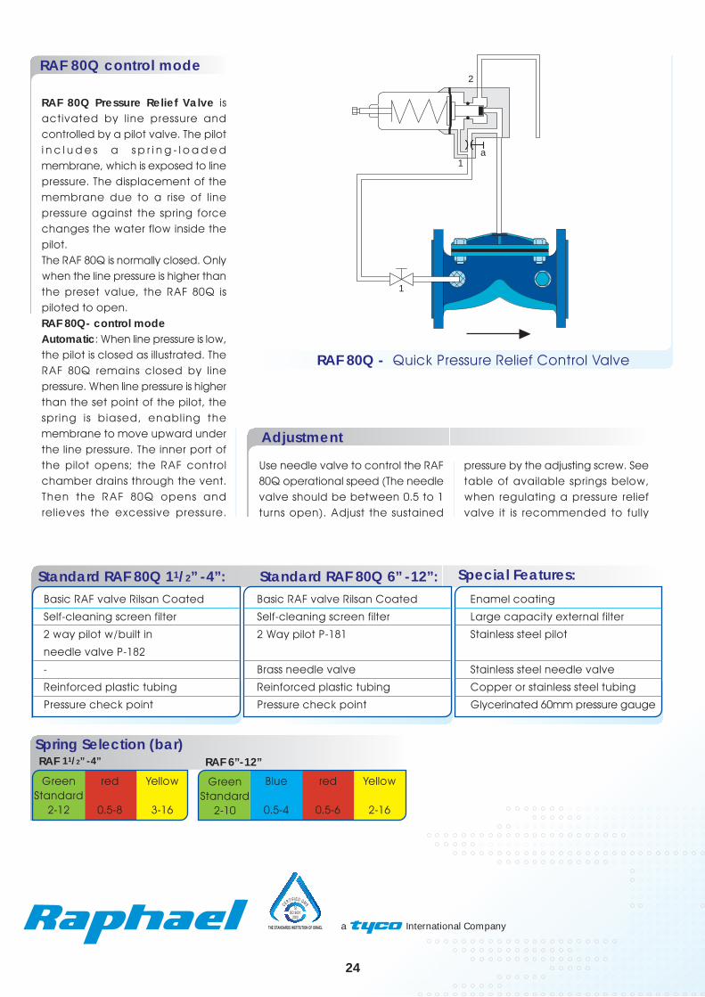
RAF 80Q Pressure Relief Valve isactivated by line pressure andcontrolled by a pilot valve. The piloti n c l u d e s a s p r i n g - l o a d e dmembrane, which is exposed to linepressure. The displacement of themembrane due to a rise of linepressure against the spring forcechanges the water flow inside thepilot.The RAF 80Q is normally closed. Onlywhen the line pressure is higher thanthe preset value, the RAF 80Q ispiloted to open.RAF 80Q- control modeAutomatic: When line pressure is low,the pilot is closed as illustrated. TheRAF 80Q remains closed by linepressure. When line pressure is higherthan the set point of the pilot, thespring is biased, enabling themembrane to move upward underthe line pressure. The inner port ofthe pilot opens; the RAF controlchamber drains through the vent.Then the RAF 80Q opens andrelieves the excessive pressure.
Adjustment
Use needle valve to control the RAF80Q operational speed (The needlevalve should be between 0.5 to 1turns open). Adjust the sustained
RAF 80Q - Quick Pressure Relief Control Valve
Standard RAF 80Q 11/2” -4”: Special Features:
Basic RAF valve Rilsan Coated Basic RAF valve Rilsan Coated Enamel coating
Self-cleaning screen filter Self-cleaning screen filter Large capacity external filter
2 way pilot w/built in 2 Way pilot P-181 Stainless steel pilot
needle valve P-182
- Brass needle valve Stainless steel needle valve
Reinforced plastic tubing Reinforced plastic tubing Copper or stainless steel tubing
Pressure check point Pressure check point Glycerinated 60mm pressure gauge
Standard RAF 80Q 6” -12”:
RAF 6”-12”Spring Selection (bar)RAF 11/2” -4”
24
Blue
0.5-4
red
0.5-6
GreenStandard
2-10
Yellow
2-16
red
0.5-8
GreenStandard
2-12
Yellow
3-16
a
1
2
1
pressure by the adjusting screw. Seetable of available springs below,when regulating a pressure reliefvalve it is recommended to fully

Use the pressure sustaining/relief valve to maintain constant upstreampressure and to avoid undesirable high pressure. This protection is requiredfor most irrigation devices, domestic and industrial utilities. Use RAF 80/82for general water supply systems with medium pressure rating. Theelaborated 2-way command with Raphael’s patented diaphragm enablessmooth and precise pressure control.
RAF
Nominal Diameter
mm Inch
40
50
65
80-50-80
80-65-80
80
100-80-100
100
125-100-125
150-100-150
150
200
250
300
1.5
2
2.5
3-2-3
3-2.5-3
3
4-3-4
4
5-4-5
6-4-6
6
8
10
12
Typical Application
Description
Recommended Flow
G E N E R A L P U R P O S E H Y D R A U L I C VA LV E S
RAF 80 and RAF 82 are piloted
hydraulic valves activated by line
pressure. The pilot valve has a
spring- loaded membrane, which
is exposed to the upstream pressure.
The valve is normally closed. Only
when the line pressure rises above
a preset point, the RAF 80/82 opens
to relieve the excessive pressure
downstream without causing surge
hazards. When the line pressure
drops the RAF closes.
RAF 80/82 Two Way Pressure Sustaining/Relief Control Valve
25
45
70
50
70
90
90
150
150
150
320
550
950
1200
Flow Rate Max.M3/hMax.
RAF 80
RAF 82
25

a International Company
RAF 80/82 control mode
Manual: To open the RAF 80, closecocks 1 and 2 and open the Vent.To close the RAF open cock 1 andclose cock 2 and Vent.
Automatic: When the upstreampressure is lower than that of thesustained pressure set point, the RAFcontrol chamber is connected tothe line, as illustrated. The RAF isclosed. When the upstream pressurerises above the set point, the pilot’smembrane is forced upward.
RAF Pressure Sustaining/Relief Valveis activated by line pressure andcontrolled by a pilot valve. The piloti n c l u d e s a s p r i n g - l o a d e dmembrane. A sustained pressure ispreset by adjusting the pilotretaining spring. The pilot isconnected to line (upstream)pressure. The displacement of thepilot spring-loaded membrane dueto upstream pressure defines theflow directions inside the pilot.When the upstream pressure ishigher than the set point, the RAFvalve is piloted to open. Theexcessive line pressure is relieveddownstream. Otherwise the RAFremains closed, maintainingconstant upstream pressure.As in two-way configurations, theRAF’s control chamber drainsdownstream, enabling faster andgradual opening without water spill.
Adjustment
Use needle valve “a” to control theRAF 80 operational speed. Adjustthe sustained pressure by theadjusting screw. See table ofavailable springs on the next page.
Standard RAF 80: Special Features:
Basic RAF valve Rilsan Coated Basic RAF valve Rilsan Coated Enamel coating
Self-cleaning screen filter Self-cleaning screen filter Large capacity external filter
2 Way pilot P-181 2 way pilot w/built in needle Stainless steel pilotvalve P-182
Brass needle valve - Stainless steel needle valve
Reinforced plastic tubing Reinforced plastic tubing Copper or stainless steel tubing
Pressure check point Pressure check point Glycerinated 60mm pressure gauge
Standard RAF 82:
Please Specify:Minimum & maximum flow rates.Normal line pressure. Set point(sustain) pressure.
RAF 82 – General Applicationtwo-way Pressure sustaining/reliefvalve. Pressure setup up to 16 bars.Diameters 11/2” to 4” (DN40 toDN100).RAF 80 – General Application two-way Pressure sustaining/ relief valve.Pressure setup up to 16 bars.
VENT
1 2
a
21
3
ADJ.
3
RAF 80 - Two Way PilotRAF 82 - Two Way Pilot
Spring Selection (bar)RAF 80 RAF 82
Blue
0.5-4
red
0.5-6
GreenStandard
2-10
Yellow
2-16
red
0.5-8
GreenStandard
2-12
Yellow
3-16
26
2
1 a
2
1
Port 1 opens, the control chamberof the RAF drains downstream andthe RAF 80 opens to relieve theexcessive pressure.

Use the pressure sustaining/relief valve to maintain constant upstreampressure and to avoid undesirable high pressure. This protection is requiredfor most irr igation devices, domestic and industrial uti l it ies.RAF 83B - General Application three-way Pressure sustaining/ relief valvewith metal pilot. Pressure setup up to 16 bars.
RAF
Nominal Diameter
mm Inch
40
50
65
80-50-80
80-65-80
80
100-80-100
100
125-100-125
150-100-150
150
200
250
300
1.5
2
2.5
3-2-3
3-2.5-3
3
4-3-4
4
5-4-5
6-4-6
6
8
10
12
Typical Application Recommended Flow
RAF 83B are piloted hydraulic
valves activated by line pressure.
The pilot valve has a spring- loaded
membrane, which is exposed to
the upstream pressure. The valve
is normally closed. Only when the
line pressure rises above a preset
point, the RAF 83B opens to relieve
the excessive pressure downstream
without causing surge hazards.
When the line pressure drops the
RAF re-closes.
RAF 83B Three Way Pressure Sustaining/Relief Control Valve
25
45
70
50
70
90
90
150
150
150
320
550
950
1200
Flow Rate Max.
M3/h
27
Description
G E N E R A L P U R P O S E H Y D R A U L I C VA LV E S

a International Company
RAF 83B control mode
The RAF closes to sustain theupstream pressure. When theupstream pressure is higher thanpreset, it overcomes the pilot springand force the pilot membrane tomove upward. Then ports 2-3 openand port 4 closes. The RAF 83Bcontrol chamber drains and thevalve opens to relieve the excessivepressure downstream.
RAF Pressure Sustaining/Relief Valveis activated by line pressure andcontrolled by a pilot valve. The piloti n c l u d e s a s p r i n g - l o a d e dmembrane. A sustained pressure ispreset by adjusting the pilot retainingspring. The pilot is connected to line(ups t ream) p res su re . Thedisplacement of the pilot spring-loaded membrane due to upstreampressure defines the flow directionsinside the pilot.When the upstream pressure ishigher than the set point, the RAFvalve is piloted to open. Theexcessive line pressure is relieveddownstream. Otherwise the RAFremains closed, maintainingconstant upstream pressure. As inthree-way configurations, the RAF’scontrol chamber drains out,enabling the valve to open fully.
RAF 83B - control mode
Automatic: The three-way cockshould be positioned at A. Whenthe upstream pressure is low, thepilot’s membrane is in its lowerposition as illustrated. The RAF 83control chamber is exposed to linepressure through the ports 4-2 of thepilot.
Special Features:
Basic RAF valve Rilsan Coated Enamel coating
Self-cleaning screen filter Large capacity external filter
3 way brass pilot P-683 Stainless steel pilot
Selecting cock valve -
Reinforced plastic tubing Copper or stainless steel tubing
Pressure check point Glycerinated 60mm pressure gauge
Standard RAF 83B:
RAF 83B - Three Way Metal Pilot
Spring Selection (bar)RAF 83B
red
0.5-8
GreenStandard
2-12
Yellow
3-16
28
AdjustmentAdjust pressure set points by theadjusting screws of the pilots. Seethe list of available springs below.
2
C
1
3
A
Manual: Use the three-way cock toclose or open the RAF by turningthe handle to the C or O positions,respectively.

Use a surge-anticipating valve to protect water lines against water hammerdamages. Uphill supply lines of considerable length and large diameterpipes are more suscept ible to water hammer damages.For more info or hazard analysis of a particular network consult RaphaelEngineers.
RAF
Nominal Diameter
mm Inch
40
50
65
80-50-80
80-65-80
80
100-80-100
100
125-100-125
150-100-150
150
200
250
300
1.5
2
2.5
3-2-3
3-2.5-3
3
4-3-4
4
5-4-5
6-4-6
6
8
10
12
Typical Application Recommended Flow
RAF 88 is adjusted to eliminatehazardous pressure surges typicalof water hammer conditions. Awater hammer is caused by anabrupt shutoff of a pump or rapidclosure of a main valve, causing afast propagation of low-pressurefront, followed by an extremely high-pressure back-wave. A series ofpressure waves, each onecomposed of alternating low andhigh pressure is created within a fewseconds.RAF 88 is a piloted hydraulic valveactivated by line pressure. The valvehas two pilots, for high and lowpressure. Under normal conditionsthe RAF 88 is closed. It opens whenthe line pressure drops below apreset pressure, in anticipation tothe following surge, and remainsopen until the fluctuations subside.
35
60
80
60
100
120
120
180
200
200
400
750
1150
1700
Flow Rate M3/h
Max.
R A F 8 8 S u r g e A n t i c i p a t i n g C o n t r o l Va l v e
RAF 88 is located next to a booster pump to protect the supply line downstream ofthe pump from water hammer damages.
29
G E N E R A L P U R P O S E H Y D R A U L I C VA LV E S
Description

RAF 88 control mode
The RAF control chamber isconnected directly to the linepressure through needle valve a.The RAF is closed. When line pressuredrops below the lower set point, thespring of the low-pressure pilot (left)push the pi lot’s membranedownward and on the way opensport 2, as shown in the drawing. Theright pilot does not change. The RAFcontrol chamber drains out throughport 2 -Vent b of the left pilot. TheRAF 88 opens in anticipation to asurge. The pressure drop is soonfollowed by a surge, which closesthe left pilot but opens the right one(the high pressure pilot) at the same
RAF Surge Anticipating hydraulicValve is activated by line pressureand controlled by two pilot valves.Both pilots include spring-loadedmembranes. The low-pressure pilot(the left one in the drawings) ispreset to open the RAF 88 graduallywhen the line pressure drops about10m below normal.The high-pressure pilot (on the right)is preset to open the RAF 88 whenthe line pressure rises about 10mabove normal. The RAF is normallyclosed. Only when the line pressuredrops below or rises above thepreset limits, the RAF 88 is piloted toopen. A water hammer event startswith a considerable pressure drop,which cause the RAF 88 to open.Then, as the water wave rollingbackward, the valve remains openand let the pressure out to diminishits impact.
RAF 88- control mode
Manual: To open the RAF 88, closecocks 1,2 and 4 and open the Vent.Automatic: The RAF 88 is normallyclosed. Ensure that all cock valves(except the vent) are fully open.Normally, line pressure is higher thanthe set point of the low-pressure pilot(the left one), but lower than thatof the high-pressure pilot (the rightone). Thus, ports 2 in both pilots areclosed. There is no flow from themain line to the pilots.
time. The RAF control chamber nowdrains through ports 2-3 of the rightpilot and thus remains open. Thehigh-pressure wave is allowed to flowthrough. After the surges subside,and the line pressure returns tonormal level, both pilots close andthe RAF 88 follows suit.
Adjustment
Use needle valve a-b to control theRAF operational speed. Adjust thelow and high pilot’s set points by theadjusting screws. See list of availablesprings below.
MA
IN L
INE
a
b
1
2
3
VENT
3
ADJ.ADJ.
4
RAF 88 - Surge Anticipating Hydraulic Valve
Standard RAF 88: Special Features:Basic RAF valve Rilsan Coated Enamel coating
Self-cleaning screen filter Large capacity external filter
2 way pilot P-181 2 way high capacity pilot P-181-3/4
2 way pilot P-161B 2 way high capacity pilot P-161B-3/4
Brass needle valves -
Reinforced plastic tubing Copper or stainless steel tubing
60mm pressure gauge Glycerinated 60mm pressure gauge
Spring Selection (bar)RAF 88
Blue
0.5-4
red
0.5-6
GreenStandard
2-10
Yellow
2-16
30
a International Company
1
2
21

Use Anti-Burst Control valve to eliminate water loss and damage due topiping burst. The valve is best in networks susceptible to burst due to oldpiping, vandalism or pressure surge. The RAF 90 features a metal pilot valveand hydraulic relay to ensure precise and reliable response in general use.
RAF
Nominal Diameter
m m Inch
40
50
65
80-50-80
80-65-80
80
100-80-100
100
125-100-125
150-100-150
150
200
250
300
1.5
2
2.5
3-2-3
3-2.5-3
3
4-3-4
4
5-4-5
6-4-6
6
8
10
12
Typical Application Recommended Flow
RAF 90 are piloted hydraulicvalves activated by line pressure.Normally the valve is open. Onlyin case of flow rate higher thana preset maximum, due to a bursto r e x c e s s i v e d e m a n ddownstream, the RAF 90/93 areautomatically closed down andcan reopen manually. The actualflow rate through the RAF 90 isdetermined by comparing theheadloss across an orifice plate.The valve is closed down by ahydraulic relay.
Flow Rate Max.M3/h
25
45
60
50
70
90
90
150
150
150
320
550
950
1200
R A F 9 0 A n t i - B u r s t C o n t r o l Va l v e
RAF 90 valve controls a water supply network downhill of a reservoir.
31
Description
G E N E R A L P U R P O S E H Y D R A U L I C VA LV E S

a International Company
RAF 90 control mode
Standard RAF 90: Special Features:
Basic RAF valve Rilsan Coated Enamel coatingSelf-cleaning screen filter Large capacity external filter2 way metal pilot P-100 3 way metal pilot P-103Brass Needle valves -Orifice plate -3 way hydraulic relay -Reinforced plastic tubing Copper or stainless steel tubing
RAF Anti-Burst Control Valve isactivated by line pressure andcontrol led by a pi lot valve.The pi lot inc ludes a spr ing-loaded membrane.An orifice plate is installed down-or upst ream of the RAF 90.The orif ice size is prepared inadvance to suit the specifiedmaximum allowable flow rate.The head loss across the orificei s proport ional to f low ratethrough the RAF 90.This head loss is transferred tothe opposite sides of the pilotmembrane. When it exceeds thepreset point of the pilot’s spring,a hydraulic relay is operated toclose down the RAF 90.The RAF 90 is reopened onlymanually.
RAF 90- control modeManual: Use the manual overrideoption of the hydraulic relay.
Automat ic : Set the manualoverride handle of the hydraulicrelay on automatic pos i t ion(designated R2).
RAF 90 - General Applicationtwo-way Anti-Burst Control HydraulicValve. Pressure rating up to 16 bars.Hydraulic relay guarantees tightclosing and manual reopening.
Please Specify:Maximum flow rate (Set point)
Adjustment
Use the needle valve a to controlthe RAF 90 operational speed.Adjust the operational set pointby the adjusting screw. See thelist of available springs below
VENTVENT
OR.
ADJ.
1
23
1
42
a R1
R2 b
3 4s
32
In normal flow rate, the pilot isclosed, as shown.The RAF contro l chamber i sallowed to drain out through therelay’s vent. The RAF 90 is fullyopen. When the head loss acrossthe orifice exceeds the presetlevel, the pi lot membrane ispushed upward with its plunger.The line pressure flowing via pilotports 3-4 flips the hydraulic relayto its other position (designatedR1). The l ine pressure is thendirected to the RAF’s control
chamber. The RAF closes. Afterthe problem is fixed, reopen theRAF by resetting the hydraulicrelay manually and shift back toauto position.
RAF 90 - Two Way Pilot

North Industrial Zone Or-Aqiva 30600, P.O.Box 555, IsraelTEL. 972-4-6263555, Fax. 972-4-6263558E-mail:[email protected] www.raphael.co.ila International Company
Raph
ael V
alve
s In
dust
ries
(197
5) L
td. m
ay m
odify
any
det
ails
or p
rodu
ct s
peci
ficat
ions
desc
ribed
in th
is pu
blica
tion
at a
ny ti
me,
with
out p
rior n
otice
, for
tech
nica
l or o
ther
reas
ons.
RAF-
041