Embed Size (px)
Citation preview

KNF 121240-121506 09/19 Translation of original Operating and Installation Instructions, english
Diaphragm Vacuum
Pumps and Compressors
N 813.3 ANE N 813.4 ANE N 813.5 ANE
Translation of original Operating and Installation Instructions
Read and observe these
Operating and Installation
Instructions!
N 813.3 ANDC-B N 813.3 AN.29DC-B
N 813.4 ANDC-B N 813.4 AN.29DC-B
Contents Page
1. About this document ................................................................. 2 2. Use ........................................................................................... 3 3. Safety ....................................................................................... 4 4. Technical data .......................................................................... 6 5. Assembly and function ........................................................... 13 6. Installation and connection ..................................................... 16 7. Operation ................................................................................ 22 8. Servicing ................................................................................. 29 9. Troubleshooting ...................................................................... 34 10. Spare parts and accessories .................................................. 37 11. Returns ................................................................................... 38
KNF Neuberger GmbH Alter Weg 3 79112 Freiburg
Germany
Phone +49 (0)7664 / 5909-0 Fax +49 (0)7664 / 5909-99
E-mail: [email protected] www.knf.de

About this document Diaphragm Vacuum Pumps N 813
2 Translation of original Operating and Installation Instructions, english, KNF 121240-121506 09/19
1. About this document
1.1. Use of the Operating and Installation Instruc-tions
The Operating and Installation Instructions are part of the pump.
Forward the Operating and Installation Instructions to any
subsequent owners of the pump.
Customer-specific project pumps (pump models which begin with
"PJ" or "PM") may differ from the Operating and Installation In-
structions.
In case of project pumps, take note of any additionally agreed
specifications.
1.2. Symbols and markings
Warning
WARNING
This symbol indicates a potential danger. It also indicates the possible consequences of failure
to observe the warning. The signal word (i.e. “Warn-
ing”) indicates the level of danger. Here you will see actions for avoiding the danger
and potential consequences.
Danger levels
Signal word Meaning Consequences if not observed
DANGER warns of immediate danger
Consequences include death or serious injuries and/or serious property damage.
WARNING warns of potential danger
Death or serious injuries and/or serious property dam-age are possible.
CAUTION warns of a poten-tially dangerous situation
Minor injuries or damage to property are possible.
Tab. 1
Other information and symbols
This indicates an activity (step) that must be carried out.
1. This indicates the first step of an activity to be carried out. Any
additional steps are consecutively numbered.
This symbol indicates important information.
Project pumps

Diaphragm Vacuum Pumps N 813 Use
Translation of original Operating and Installation Instructions, english, KNF 121240-121506 09/19 3
2. Use
2.1. Intended use
The pumps are exclusively intended for transferring gases and
vapors.
Owner's responsibility
Only install and operate the pumps under the operating parameters
and conditions described in Chapter 4. Technical data.
Only complete pumps may be taken into service.
Make sure that the installation location is dry and the pump is
protected against water in the form of rain, spray, splashes and
drips.
Before using a medium, check whether the medium can be trans-
ferred danger-free in the specific application case.
Before using a medium, check the compatibility of the materials of
the pump head, diaphragm, and valves with the medium.
Only transfer gases which remain stable under the pressures and
temperatures occurring in the pump.
2.2. Improper use
The pumps must not be operated in an explosive atmosphere.
The pumps are not suitable for transferring dust.
The pumps are not suitable for transferring liquids.
The pumps are not suitable for use with aggressive media. Other
pumps in the KNF product line are designed for use with aggres-
sive media. Please contact us for more information.
The pumps must not be used to create vacuum and pressure
simultaneously.
Never apply positive pressure to the suction side of the pump.
Operating parameters and
conditions
Requirements for
transferred medium

Safety Diaphragm Vacuum Pumps N 813
4 Translation of original Operating and Installation Instructions, english, KNF 121240-121506 09/19
3. Safety
Observe the safety precautions in Chapters
6. Installation and connection and 7. Operation. The pumps are built according to generally recognized rules of
technology and in accordance with the pertinent occupational
safety and accident prevention regulations. Nevertheless, potential
dangers during use can result in injuries to the user or others or in
damage to the pump or other property.
Only use the pumps when they are in a good technical and proper
working order, in accordance with their intended use, observing the
safety advice within the Operating and Installation Instructions, at
all times.
Make sure that only trained and instructed personnel or specially
trained personnel work on the pumps. This applies especially to
assembly, connection, and servicing work.
Make sure that all personnel have read and understood the Oper-
ating and Installation Instructions, especially the "Safety" chapter.
Observe the accident prevention and safety regulations when
performing any work on the pump and during operation.
Ensure that the pump is separated from the mains and is de-
energized.
When transferring dangerous media, observe the safety regula-
tions for handling such media.
Be aware that the pumps are not designed to be explosion-proof.
Make sure that the temperature of the medium is always sufficient-
ly below its ignition temperature, to avoid ignition or explosion. This
also applies to unusual operating situations.
Note that the temperature of the medium increases when the pump
compresses the medium.
Hence, make sure that the temperature of the medium is sufficient-
ly below its ignition temperature, even when it is compressed to
maximum permissible operating pressure of the pump. The pump's
maximum permissible operating pressure is stated in the Technical
data (see Chapter 4).
Consider any external sources of energy, such as sources of
radiation, that could additionally heat the medium.
In case of doubt, consult the KNF customer service.
All replacement parts should be properly stored and disposed of in
accordance with the applicable environmental protection regula-
tions. Ensure adherence to the pertinent national and international
regulations. This applies especially to parts contaminated with toxic
substances.
For the purposes of Machinery Directive 2006/42/EC, pumps are
“partly completed machinery,” and are therefore to be regarded as
not ready for use. Partly completed machinery may not be com-
missioned until such time as it has been determined that the ma-
Personnel
Working in a
safety-conscious manner
Handling dangerous media
Handling flammable
media
Environmental protection
EC directives / standards

Diaphragm Vacuum Pumps N 813 Safety
Translation of original Operating and Installation Instructions, english, KNF 121240-121506 09/19 5
chine in which the partly completed machinery is to be assembled
conforms to the provisions of the Machinery Directive 2006/42/EC.
The following essential requirements of Annex I of Directive
2006/42/EC (general principles) are applied and observed:
− General Principles No. 1
− No. 1.1.2. / 1.1.3. / 1.3.1. / 1.3.3. / 1.3.4. / 1.4.1. / 1.5.1.* /
1.5.2.* / 1.5.8. / 1.5.9. / 1.7.4. / 1.7.4.1. / 1.7.4.3.
(* only for pumps with AC motor)
As these partly completed machinery are OEM-models the power
supplies and the equipment for disconnecting and switching-off the
partly completed machinery respectively have to be considered
when mounting as well as over-current and overload protective
gear.
In addition a protection against mechanical parts in motion and hot
parts, if existing, has to be provided when mounting.
The pumps conform to the Directive 2011/65/EU.
The following harmonized standards are met:
N 813.3 ANE
N 813.4 ANE
N 813.5 ANE
N 813 ANDC-B
N 813 AN.29DC-B
DIN EN 50581 DIN EN 50581
DIN EN 55014-1/2 DIN EN 61000-6-2/3
DIN EN 61000-3-2/3
DIN EN 60204-1 Tab. 2
All repairs to the pump(s) must be carried out by the relevant KNF
Customer Service team.
Housings with voltage-caring parts may be opened by technical
personnel only.
Use only genuine parts from KNF for servicing work.
Customer services and
repairs

Technical data Diaphragm Vacuum Pumps N 813
6 Translation of original Operating and Installation Instructions, english, KNF 121240-121506 09/19
4. Technical data N 813.3 ANE
Pneumatic performance
Max. permissible operating pressure [bar g]
1
Ultimate vacuum [mbar abs.] 3
Flow rate at atm. pressure [l/min]*
13
Pneumatic connections
Thread size G 1/8
Ambient and media temperature
Permissible ambient temperature
+ 5 °C to + 40 °C
Permissible media temperature + 5 °C to + 40 °C
Other parameters
Weight [kg] 5.9
Dimensions: L x H x W [mm] approx. 230 x 148 x 140
Maximum permissible ambient relative humidity
80 % for temperatures up to 31 °C, decreasing linearly to 50 % at 40 °C
Maximum altitude of installation [m above sea level]
2000
Electrical data
Voltage / Frequencies
See type label Max. operating current
Pump power consumption
Maximum permissible mains voltage fluctuations
+/- 10 %
Motor protection class IP 44
Pump materials
Pump head Aluminium
Diaphragm EPDM
Valve EPDM Tab. 3 * liters in standard state (1013 mbar)
For pumps with thermo switch:
The pumps are fitted with a thermo switch to protect against over-
loading.
WARNUNG
Automatic starting can cause personal injury and
pump damage When the operation of the pump is interrupted by the
thermal switch, the pump will restart automatically
after cooling down.
Take all necessary care to prevent this leading
to a dangerous situation.
Thermo switch
Diaphragm Vacuum Pumps N 813 Technical data
Translation of original Operating and Installation Instructions, english, KNF 121240-121506 09/19 7
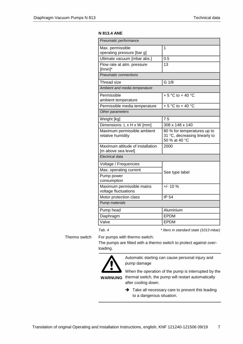
N 813.4 ANE
Pneumatic performance
Max. permissible operating pressure [bar g]
1
Ultimate vacuum [mbar abs.] 0.5
Flow rate at atm. pressure [l/min]*
13
Pneumatic connections
Thread size G 1/8
Ambient and media temperature
Permissible ambient temperature
+ 5 °C to + 40 °C
Permissible media temperature + 5 °C to + 40 °C
Other parameters
Weight [kg] 7.5
Dimensions: L x H x W [mm] 308 x 148 x 140
Maximum permissible ambient relative humidity
80 % for temperatures up to 31 °C, decreasing linearly to 50 % at 40 °C
Maximum altitude of installation [m above sea level]
2000
Electrical data
Voltage / Frequencies
See type label Max. operating current
Pump power consumption
Maximum permissible mains voltage fluctuations
+/- 10 %
Motor protection class IP 54
Pump materials
Pump head Aluminium
Diaphragm EPDM
Valve EPDM Tab. 4 * liters in standard state (1013 mbar)
For pumps with thermo switch:
The pumps are fitted with a thermo switch to protect against over-
loading.
WARNUNG
Automatic starting can cause personal injury and
pump damage When the operation of the pump is interrupted by the
thermal switch, the pump will restart automatically
after cooling down.
Take all necessary care to prevent this leading
to a dangerous situation.
Thermo switch

Technical data Diaphragm Vacuum Pumps N 813
8 Translation of original Operating and Installation Instructions, english, KNF 121240-121506 09/19
N 813.5 ANE
Pneumatic performance
Max. permissible operating pressure [bar g]
1
Ultimate vacuum [mbar abs.] 1
Flow rate at atm. pressure [l/min]*
19
Pneumatic connections
Thread size G 1/8
Ambient and media temperature
Permissible ambient temperature
+ 5 °C to + 40 °C
Permissible media temperature + 5 °C to + 40 °C
Other parameters
Weight [kg] 7.5
Dimensions: L x H x W [mm] 308 x 148 x 140
Maximum permissible ambient relative humidity
80 % for temperatures up to 31 °C, decreasing linearly to 50 % at 40 °C
Maximum altitude of installation [m above sea level]
2000
Electrical data
Voltage / Frequencies
See type label Max. operating current
Pump power consumption
Maximum permissible mains voltage fluctuations
+/- 10 %
Motor protection class IP 54
Pump materials
Pump head Aluminium
Diaphragm EPDM
Valve EPDM Tab. 5 * liters in standard state (1013 mbar)
For pumps with thermo switch:
The pumps are fitted with a thermo switch to protect against over-
loading.
WARNUNG
Automatic starting can cause personal injury and
pump damage When the operation of the pump is interrupted by the
thermal switch, the pump will restart automatically
after cooling down.
Take all necessary care to prevent this leading
to a dangerous situation.
Thermo switch
Diaphragm Vacuum Pumps N 813 Technical data
Translation of original Operating and Installation Instructions, english, KNF 121240-121506 09/19 9
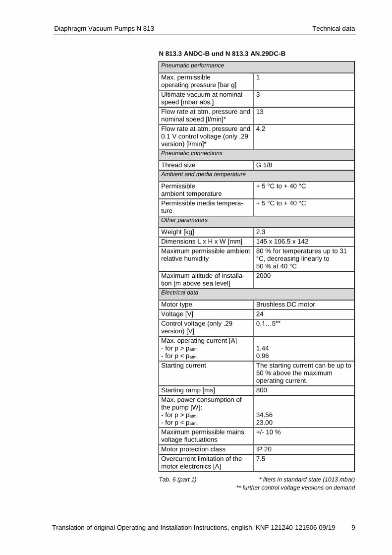
N 813.3 ANDC-B und N 813.3 AN.29DC-B
Pneumatic performance
Max. permissible operating pressure [bar g]
1
Ultimate vacuum at nominal speed [mbar abs.]
3
Flow rate at atm. pressure and nominal speed [l/min]*
13
Flow rate at atm. pressure and 0.1 V control voltage (only .29 version) [l/min]*
4.2
Pneumatic connections
Thread size G 1/8
Ambient and media temperature
Permissible ambient temperature
+ 5 °C to + 40 °C
Permissible media tempera-ture
+ 5 °C to + 40 °C
Other parameters
Weight [kg] 2.3
Dimensions L x H x W [mm] 145 x 106.5 x 142
Maximum permissible ambient relative humidity
80 % for temperatures up to 31 °C, decreasing linearly to 50 % at 40 °C
Maximum altitude of installa-tion [m above sea level]
2000
Electrical data
Motor type Brushless DC motor
Voltage [V] 24
Control voltage (only .29 version) [V]
0.1…5**
Max. operating current [A] - for p > patm. - for p < patm.
1.44 0.96
Starting current The starting current can be up to 50 % above the maximum operating current.
Starting ramp [ms] 800
Max. power consumption of the pump [W]: - for p > patm.
- for p < patm.
34.56 23.00
Maximum permissible mains voltage fluctuations
+/- 10 %
Motor protection class IP 20
Overcurrent limitation of the motor electronics [A]
7.5
Tab. 6 (part 1) * liters in standard state (1013 mbar)
** further control voltage versions on demand

Technical data Diaphragm Vacuum Pumps N 813
10 Translation of original Operating and Installation Instructions, english, KNF 121240-121506 09/19
Pump materials
Pump head Aluminium
Diaphragm PTFE-coated
Valve EPDM Tab. 6 (part 2)
The pump is protected against overheating by a temperature
sensor on the motor board and equipped with overcurrent
protection.
If one of these safety functions is triggered or if the maximum
blocking time of the rotor is exceeded due to a fault, the pump
will be shut down and must be manually reset, as follows:
Separate pump from the mains.
Remove the cause(s) of the fault before restarting.

Diaphragm Vacuum Pumps N 813 Technical data
Translation of original Operating and Installation Instructions, english, KNF 121240-121506 09/19 11
N 813.4 ANDC-B und N 813.4 AN.29DC-B
Pneumatic performance
Max. permissible operating pressure [bar g]
1
Ultimate vacuum at nominal speed [mbar abs.]
0.5
Flow rate at atm. pressure and nominal speed [l/min]*
13
Flow rate at atm. pressure and 0.1 V control voltage (only .29 version) [l/min]*
3.5
Pneumatic connections
Thread size G 1/8
Ambient and media temperature
Permissible ambient temperature
+ 5 °C to + 40 °C
Permissible media tempera-ture
+ 5 °C to + 40 °C
Other parameters
Weight [kg] 3.8
Dimensions L x H x W [mm] 230 x 106.5 x 144
Maximum permissible ambient relative humidity
80 % for temperatures up to 31 °C, decreasing linearly to 50 % at 40 °C
Maximum altitude of installa-tion [m above sea level]
2000
Electrical data
Motor type Brushless DC motor
Voltage [V] 24
Control voltage (only .29 version) [V]
0.1…5**
Max. operating current [A] - for p > patm. - for p < patm.
2.7 1.6
Starting current The starting current can be up to 50 % above the maximum operating current.
Starting ramp [ms] 800
Max. power consumption of the pump [W]: - for p > patm.
- for p < patm.
64.8 38.4
Maximum permissible mains voltage fluctuations
+/- 10 %
Motor protection class IP 20
Overcurrent limitation of the motor electronics [A]
7.5
Tab. 7 (part 1) * liters in standard state (1013 mbar)
** further control voltage versions on demand

Technical data Diaphragm Vacuum Pumps N 813
12 Translation of original Operating and Installation Instructions, english, KNF 121240-121506 09/19
Pump materials
Pump head Aluminium
Diaphragm EPDM
Valve EPDM Tab. 7 (part 2)
The pump is protected against overheating by a temperature
sensor on the motor board and equipped with overcurrent
protection.
If one of these safety functions is triggered or if the maximum
blocking time of the rotor is exceeded due to a fault, the pump
will be shut down and must be manually reset, as follows:
Separate pump from the mains.
Remove the cause(s) of the fault before restarting.
Diaphragm Vacuum Pumps N 813 Assembly and function
Translation of original Operating and Installation Instructions, english, KNF 121240-121506 09/19 13
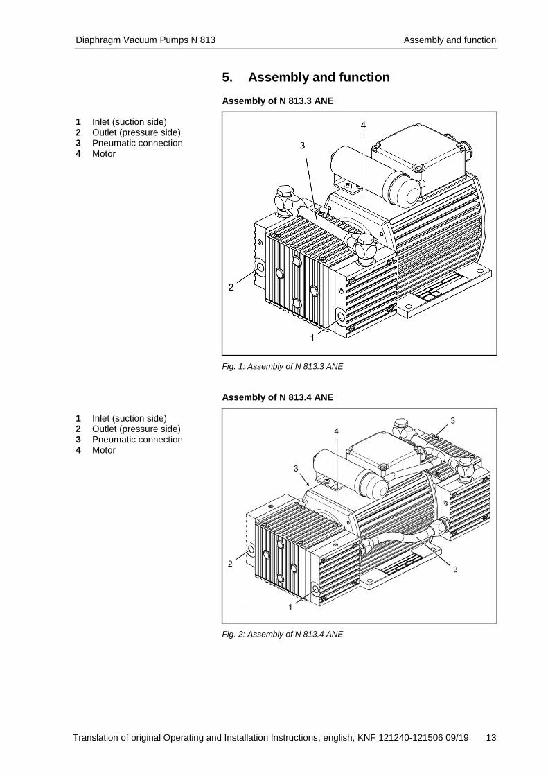
5. Assembly and function Assembly of N 813.3 ANE
1 Inlet (suction side) 2 Outlet (pressure side) 3 Pneumatic connection 4 Motor
Fig. 1: Assembly of N 813.3 ANE
Assembly of N 813.4 ANE
1 Inlet (suction side) 2 Outlet (pressure side) 3 Pneumatic connection 4 Motor
Fig. 2: Assembly of N 813.4 ANE

Assembly and function Diaphragm Vacuum Pumps N 813
14 Translation of original Operating and Installation Instructions, english, KNF 121240-121506 09/19
Assembly of N 813.5 ANE
1 Inlet (suction side) 2 Outlet (pressure side) 3 Pneumatic connection 4 Motor
Fig. 3: Assembly of N 813.5 ANE
Assembly of N 813.3 ANDC -B und N 813.3 AN.29DC-B
1 Inlet (suction side) 2 Outlet (pressure side) 3 Pneumatic connection 4 Motor
Fig. 4: Assembly of N 813.3 ANDC-B und N 813.3 AN.29DC-B

Diaphragm Vacuum Pumps N 813 Assembly and function
Translation of original Operating and Installation Instructions, english, KNF 121240-121506 09/19 15
Assembly of N 813.4 ANDC -B und N 813.4 AN.29DC-B
1 Inlet (suction side) 2 Outlet (pressure side) 3 Pneumatic connection 4 Motor
Fig. 5: Assembly of N 813.4 ANDC-B und N 813.4 AN.29DC-B
How diaphragm pumps work
1 Outlet valve 2 Inlet valve 3 Working chamber 4 Diaphragm 5 Eccentric 6 Connecting rod 7 Pump drive
Fig. 6: Pump head
Diaphragm pumps transfer, compress (depending on pump ver-
sion), and evacuate gases and vapors.
The elastic diaphragm (4) is moved up and down by the eccentric
(5) and the connecting rod (6). In the downward stroke it aspirates
the gas to be transferred via the inlet valve (2). In the upward
stroke, the diaphragm presses the medium out of the pump head
via the outlet valve (1). The diaphragm hermetically seals the
working chamber (3) from the pump drive (7).
Installation and connection Diaphragm Vacuum Pumps N 813
16 Translation of original Operating and Installation Instructions, english, KNF 121240-121506 09/19
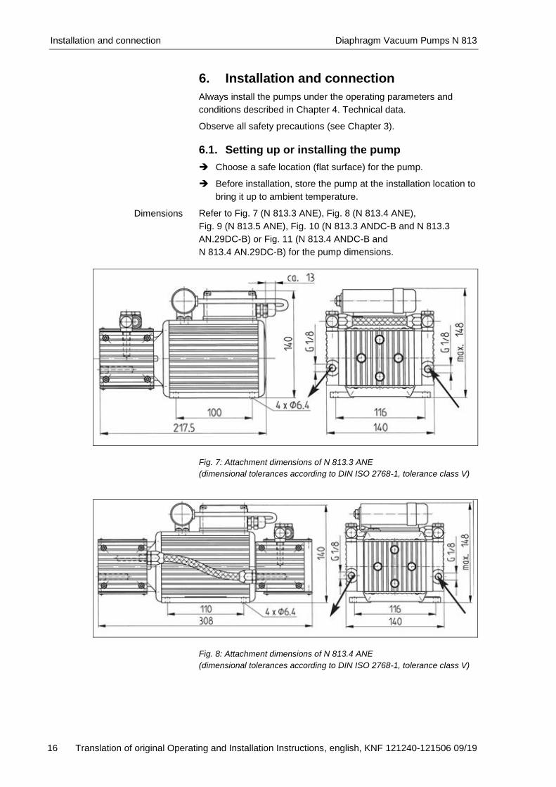
6. Installation and connection
Always install the pumps under the operating parameters and
conditions described in Chapter 4. Technical data.
Observe all safety precautions (see Chapter 3).
6.1. Setting up or installing the pump
Choose a safe location (flat surface) for the pump.
Before installation, store the pump at the installation location to
bring it up to ambient temperature.
Refer to Fig. 7 (N 813.3 ANE), Fig. 8 (N 813.4 ANE),
Fig. 9 (N 813.5 ANE), Fig. 10 (N 813.3 ANDC-B and N 813.3
AN.29DC-B) or Fig. 11 (N 813.4 ANDC-B and
N 813.4 AN.29DC-B) for the pump dimensions.
Fig. 7: Attachment dimensions of N 813.3 ANE
(dimensional tolerances according to DIN ISO 2768-1, tolerance class V)
Fig. 8: Attachment dimensions of N 813.4 ANE
(dimensional tolerances according to DIN ISO 2768-1, tolerance class V)
Dimensions
Diaphragm Vacuum Pumps N 813 Installation and connection
Translation of original Operating and Installation Instructions, english, KNF 121240-121506 09/19 17
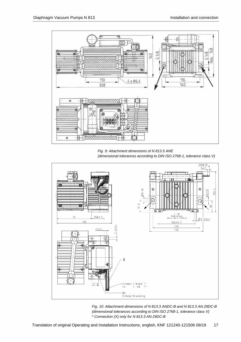
Fig. 9: Attachment dimensions of N 813.5 ANE
(dimensional tolerances according to DIN ISO 2768-1, tolerance class V)
Fig. 10: Attachment dimensions of N 813.3 ANDC-B and N 813.3 AN.29DC-B
(dimensional tolerances according to DIN ISO 2768-1, tolerance class V)
* Connection (X) only for N 813.3 AN.29DC-B

Installation and connection Diaphragm Vacuum Pumps N 813
18 Translation of original Operating and Installation Instructions, english, KNF 121240-121506 09/19
Fig. 11: Attachment dimensions of N 813.4 ANDC-B and N 813.4 AN.29DC-B
(dimensional tolerances according to DIN ISO 2768-1, tolerance class V)
* Connection (X) only for N 813.4 AN.29DC-B
Only for N 813.3 ANE:
When setting up or installing the pump, make sure that the fan
can draw in an adequate amount of cooling air.
For pumps with fan: Install the pump so as accidental finger con-
tact is with the fan is impossible.
Make sure that the installation location is dry and the pump is
protected against water in the form of rain, spray, splashes and
drips.
The pump motor's IP protection class is provided on the type
plate. Set up or install the pump at the highest point in the system to
prevent condensate from collecting in the pump head.
Protect the pump against dust.
Protect the pump against grease and oils.
Protect the pump against vibration and impact.
Cooling air supply
Installation location
Diaphragm Vacuum Pumps N 813 Installation and connection
Translation of original Operating and Installation Instructions, english, KNF 121240-121506 09/19 19
6.2. Electrical connections
GEFAHR
Extreme danger from electrical shock
Only have the pump connected by an authorized
specialist.
Only have the pump connected when the power
supply is disconnected.
When connecting the device to a power source, the relevant
standards, directives, regulations, and technical standards
must be observed.
In the electrical installation, arrangements (complying with EN
60335-1) must be made for disconnecting the pump motor
from the electrical supply.
For pumps with AC motor:
The motors of the pump must be protected according to EN
60204-1 (protection against excess current, or overloading).
For operating current see type plate.
It is recommended that an additional “Emergency Stop” switch
is installed.
The pump must be installed so that contact with live parts
(electrical connection) is impossible.
Pumps with AC motor
1. Make sure that the power supply data match the data on the
pump type plate.
The voltage must not vary by more than + 10% and - 10% from
that shown on the type-plate. 2. Connect earth (ground) wire to the motor.
3. Connect motor wires.
Pumps with brushless DC motor
1. Make sure that the power supply data match the data on the
pump type plate.
The voltage must not vary by more than + 10% and - 10% from
that shown on the type-plate. 2. Electrical connect of the pump according to Fig. 12, page 20.
Note the proper polarity (see marking on the motor). Incorrect
lead connection will damage electronics of brushless dc motors
(type designation ending with B). The supply wires have in-
verse-polarity protection on the motor board for this purpose,
while the control-voltage wires do not have this protection
function.

Installation and connection Diaphragm Vacuum Pumps N 813
20 Translation of original Operating and Installation Instructions, english, KNF 121240-121506 09/19
Control voltage may only be applied if the motor controller is
supplied with operating voltage. Otherwise damages can occur
on the motor controller.
Pin Nr.
Pin No.
Farbkodierung
Color coding
Benennung
Description
Elektrische Eigenschaft
Electrical characteristic
1 schwarz
black
DC Spannungsquelle
DC power supply
U0-DC: 5±0.2V
I0: max. 170mA
2 weiß
white
Eingang Steuerspannung
Control voltage input UIN-DC: 0…5V (PIN-MAX: ≤5mW)
fPWM-IN: 100Hz±50Hz
duty cycle: 0…100%
RIN:≥12.2kΩ @1kHz 3* grau
grey
Masse
Ground
4 lila
purple
Ausgang Fehlermeldung
Error signal output UERROR-0-DC: ≤0.6V / UERROR-1-DC: ≥4.5V…U0-DC
5* blau
blue
Masse
Ground UON-DC: ≤0.9V
UOFF-DC: ≥4.2V…U0-DC 6
grün
green
Eingang Remote EIN/AUS
Input Remote ON/OFF
7 gelb
yellow
Ausgang Drehzahlsignal
Speed signal output PWM-OUT
fPWM-OUT: 50Hz
UPWMF-OUT: U0-DC
duty cycle: 0…100%
FREQ-OUT
fFREQ-OUT: n
1 pulse / revolution
UFREQ-OUT: U0-DC 8* orange
orange
Masse
Ground
Zulässige Spannung an den Steuereingängen
allowable voltage at control inputs UDC: max. 5.5V
Zulässige Strombelastbarkeit an den Steuerausgängen
allowable ampacity at control outputs I: max. 10mA
Fig. 12: Connection plan motor electronics (connection (X) only for N 813._ AN.29DC-B)
* Ground Pin 3, 5 and 8 are connected with each other
If Pin 1 is simultaneously used as control voltage specification
for Pin 2, please contact the KNF customer services (see last
page for telephone number).

Diaphragm Vacuum Pumps N 813 Installation and connection
Translation of original Operating and Installation Instructions, english, KNF 121240-121506 09/19 21
6.3. Pneumatic connections
Connect to the pump only components that are designed to
handle the pump's pneumatic specifications (see Chapter 4.
Technical data).
When using the pump as a vacuum pump, safely divert the
pump's discharge from its pneumatic outlet.
See markings on the pump head for the direction of flow.
1. Remove protective plugs from the hose connection threads.
2. If the accessories silencer or hose connector are present,
screw them onto the corresponding hose connection threads.
Install the silencer in the pump's outlet.
3. Connect suction and pressure lines.
4. Lay the suction and pressure lines at a downward angle to
prevent condensate from running into the pump.
Connected
components
Pump discharge
Connecting the pump
Operation Diaphragm Vacuum Pumps N 813
22 Translation of original Operating and Installation Instructions, english, KNF 121240-121506 09/19
7. Operation
7.1. General
Operate the pump only under the operating parameters and
conditions described in Chapter 4. Technical data.
Make sure the pump is used properly (see Chapter 2.1).
Avoid improper use of the pump (see Chapter 2.2).
Observe the safety precautions (see Chapter 3).
The pumps are components that are intended to be incorpo-
rated into another machine. Before putting them into service it
must be established that machinery or equipment in which they
are installed meet the relevant regulations.
WARNING
Excessive pressure may cause the pump head to
burst. Do not exceed the maximum permissible operat-
ing pressure (see Chapter 4).
Monitor pressure during operation.
If pressure exceeds the maximum permissible
operating pressure, immediately switch off the
pump and eliminate the fault (see Chapter 9.
Troubleshooting).
Only throttle or regulate the air or gas in the
suction line to prevent the maximum permissible
operating pressure from being exceeded.
If the air or gas quantity is throttled or regulated
in the pressure line, make sure that the maxi-
mum permissible operating pressure is not ex-
ceeded.
Make sure that the pump outlet is not closed or
constricted.
Excessive pressure can be prevented by placing a bypass line
with a pressure relief valve between the pressure and suction
side of the pump. For further information, contact your KNF
technical adviser. When the pump stops, restore the system to normal atmos-
pheric pressure (release pneumatic pressure in pump).
For pumps with AC motor:
Do not allow the pumps to start against pressure or vacuum. If
you experience a brief power interruption, check for the pres-
ence of pressure or vacuum before restarting. If a pump starts
against pressure or vacuum, it may block. This activates the
overload switch and the pump switches off.
Make sure that there is no pressure in the hoses before switch-
ing on the pump.
Pump standstill
Switching on the pump
Diaphragm Vacuum Pumps N 813 Operation
Translation of original Operating and Installation Instructions, english, KNF 121240-121506 09/19 23
For pumps with brushless DC motor:
The pumps may start against pressure or vacuum. This is also
allowed if you experience a brief power interruption. Restore the system to normal atmospheric pressure (release
pneumatic pressure in pump).
Switching off the
pump/removing from operation
Operation Diaphragm Vacuum Pumps N 813
24 Translation of original Operating and Installation Instructions, english, KNF 121240-121506 09/19
7.2. Control functions (for pumps with brushless DC motor)
7.2.1. Speed control
DC-B (constant speed)
The motor drives the pump at a constant, unchangeable speed
across the entire permissible pressure range.
.29DC-B (regulated speed)
The motor drives the pump at a changeable speed between nmin
and nmax. Speed is specified via the control voltage.
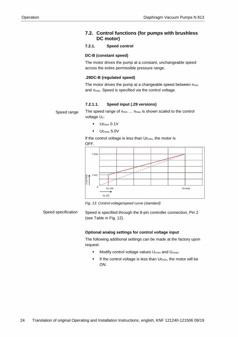
7.2.1.1. Speed input (.29 versions)
The speed range of nmin … nmax is shown scaled to the control
voltage Uc:
Ucmin: 0.1V
Ucmax: 5.0V
If the control voltage is less than Ucmin, the motor is
OFF.
Fig. 13: Control-voltage/speed curve (standard)
Speed is specified through the 8-pin controller connection, Pin 2
(see Table in Fig. 12).
Optional analog settings for control voltage input
The following additional settings can be made at the factory upon
request:
Modify control voltage values Ucmin and Ucmax
If the control voltage is less than Ucmin, the motor will be
ON.
Speed range
Speed specification

Diaphragm Vacuum Pumps N 813 Operation
Translation of original Operating and Installation Instructions, english, KNF 121240-121506 09/19 25
Fig. 14: Scaled control-voltage/speed curve (optional)
7.2.1.2. Speed output (.29 versions)
Speed is outputted through the 8-pin controller connection (Pin 7,
see Table in Fig. 12).
The motor controller generates speed-synchronized pulse-width
modulation (see Fig. 15).
Fig. 15: Analog speed output (standard)
Optional speed output
The motor controller generates a speed-synchronized right-angle
frequency with 5V TTL level (see Fig. 16).
Fig. 16: Digital speed output (optional)
7.2.2. Remote ON/OFF (.29 versions)
Remote ON/OFF is through an 8-pin controller connection (Pin 6,
see Fig. 12).
To start the motor, Pin 6 must be bridged to the ground of the
controller connection.
Speed output
Remote ON/OFF

Operation Diaphragm Vacuum Pumps N 813
26 Translation of original Operating and Installation Instructions, english, KNF 121240-121506 09/19
7.2.3. External digital activation (.29 versions, optional)
If desired, the pump motor can be activated externally. This re-
quires a special setting at the factory (see final page for contact
address).
External activation is through the 6-pin communication connection
(see Fig. 12 above).
Connector type: Micro-Match Female Top Entry
Part no.: 7-215079-6
When the motor is activated externally, the control inputs are
inactive.
Connection communication plug (see Fig. 12 top)
PIN 1 – do not connect
PIN 2 - do not connect
PIN 3 – GND
PIN 4 – 5V (max. 50 mA)
PIN 5 – TX MBLC
PIN 6 - RX MBLC
Motor connection options – external control unit
Fig. 17: External activation options (optional)
The following motor functions can be controlled:
Motor remote ON/OFF
In the factory condition, the motor is OFF when operating
voltage is applied. However, as an option the motor can be
ON when operating voltage is applied.
Motor speed
Setting motor speed within speed limits nmin and nmax.
Read-out of the following process parameters:
- Actual/Nominal motor speed
- Control limit of motor speed
- Operating current of the motor
- Temperature of the motor controller
- Fault status
- Software version number
External activation
Diaphragm Vacuum Pumps N 813 Operation
Translation of original Operating and Installation Instructions, english, KNF 121240-121506 09/19 27
The connection between the PC and motor controller can be
operated as an RS-232 interface. Accordingly, in the operating
system it is managed as an additional COM connection and can be
addressed with conventional terminal software.
Interface configuration
Baud rate: 57600 bits/s
Data bits: 8
Parity: none
Stop bits: 1
Flow control: none
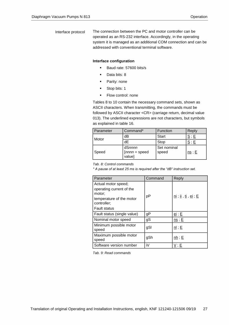
Tables 8 to 10 contain the necessary command sets, shown as
ASCII characters. When transmitting, the commands must be
followed by ASCII character <CR> (carriage return, decimal value
013). The underlined expressions are not characters, but symbols
as explained in table 16.
Parameter Command* Function Reply
Motor dB Start S ; E
dE Stop S ; E
Speed dSnnnn [nnnn = speed value]
Set nominal speed ns ; E
Tab. 8: Control commands
* A pause of at least 25 ms is required after the “dB“ instruction set.
Parameter Command Reply
Actual motor speed;
operating current of the motor;
temperature of the motor controller;
Fault status
pP ni ; ii , ti , ei ; E
Fault status (single value) gP ei ; E
Nominal motor speed gS ns ; E
Minimum possible motor speed
gSl nl ; E
Maximum possible motor speed
gSh nh ; E
Software version number iV V ; E Tab. 9: Read commands
Interface protocol
Operation Diaphragm Vacuum Pumps N 813
28 Translation of original Operating and Installation Instructions, english, KNF 121240-121506 09/19
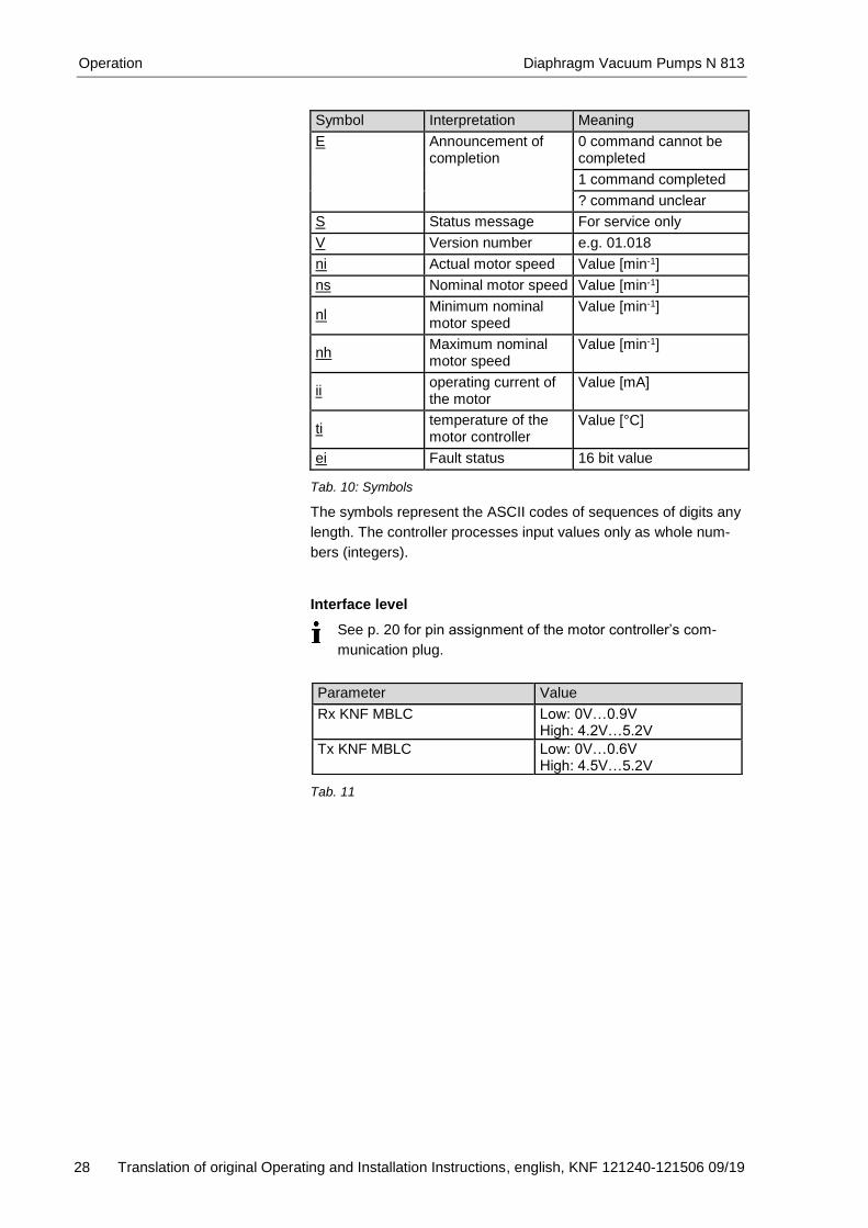
Symbol Interpretation Meaning
E Announcement of completion
0 command cannot be completed
1 command completed
? command unclear
S Status message For service only
V Version number e.g. 01.018
ni Actual motor speed Value [min-1]
ns Nominal motor speed Value [min-1]
nl Minimum nominal motor speed
Value [min-1]
nh Maximum nominal motor speed
Value [min-1]
ii operating current of the motor
Value [mA]
ti temperature of the motor controller
Value [°C]
ei Fault status 16 bit value Tab. 10: Symbols
The symbols represent the ASCII codes of sequences of digits any
length. The controller processes input values only as whole num-
bers (integers).
Interface level
See p. 20 for pin assignment of the motor controller’s com-
munication plug.
Tab. 11
Parameter Value
Rx KNF MBLC Low: 0V…0.9V High: 4.2V…5.2V
Tx KNF MBLC Low: 0V…0.6V High: 4.5V…5.2V
Diaphragm Vacuum Pumps N 813 Servicing
Translation of original Operating and Installation Instructions, english, KNF 121240-121506 09/19 29
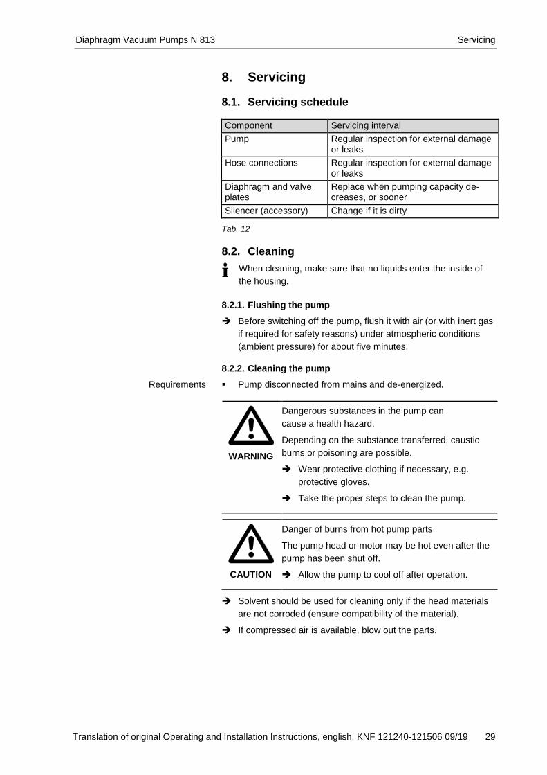
8. Servicing
8.1. Servicing schedule Component Servicing interval
Pump Regular inspection for external damage or leaks
Hose connections Regular inspection for external damage or leaks
Diaphragm and valve plates
Replace when pumping capacity de-creases, or sooner
Silencer (accessory) Change if it is dirty Tab. 12
8.2. Cleaning
When cleaning, make sure that no liquids enter the inside of
the housing.
8.2.1. Flushing the pump
Before switching off the pump, flush it with air (or with inert gas
if required for safety reasons) under atmospheric conditions
(ambient pressure) for about five minutes.
8.2.2. Cleaning the pump
Pump disconnected from mains and de-energized.
WARNING
Dangerous substances in the pump can
cause a health hazard.
Depending on the substance transferred, caustic
burns or poisoning are possible.
Wear protective clothing if necessary, e.g.
protective gloves.
Take the proper steps to clean the pump.
CAUTION
Danger of burns from hot pump parts
The pump head or motor may be hot even after the
pump has been shut off.
Allow the pump to cool off after operation.
Solvent should be used for cleaning only if the head materials
are not corroded (ensure compatibility of the material).
If compressed air is available, blow out the parts.
Requirements
Servicing Diaphragm Vacuum Pumps N 813
30 Translation of original Operating and Installation Instructions, english, KNF 121240-121506 09/19
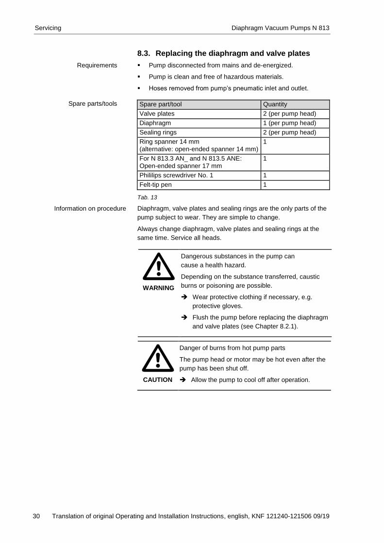
8.3. Replacing the diaphragm and valve plates
Pump disconnected from mains and de-energized.
Pump is clean and free of hazardous materials.
Hoses removed from pump’s pneumatic inlet and outlet.
Spare part/tool Quantity
Valve plates 2 (per pump head)
Diaphragm 1 (per pump head)
Sealing rings 2 (per pump head)
Ring spanner 14 mm (alternative: open-ended spanner 14 mm)
1
For N 813.3 AN_ and N 813.5 ANE: Open-ended spanner 17 mm
1
Phililips screwdriver No. 1 1
Felt-tip pen 1 Tab. 13
Diaphragm, valve plates and sealing rings are the only parts of the
pump subject to wear. They are simple to change.
Always change diaphragm, valve plates and sealing rings at the
same time. Service all heads.
WARNING
Dangerous substances in the pump can
cause a health hazard.
Depending on the substance transferred, caustic
burns or poisoning are possible.
Wear protective clothing if necessary, e.g.
protective gloves.
Flush the pump before replacing the diaphragm
and valve plates (see Chapter 8.2.1).
CAUTION
Danger of burns from hot pump parts
The pump head or motor may be hot even after the
pump has been shut off.
Allow the pump to cool off after operation.
Requirements
Spare parts/tools
Information on procedure
Diaphragm Vacuum Pumps N 813 Servicing
Translation of original Operating and Installation Instructions, english, KNF 121240-121506 09/19 31
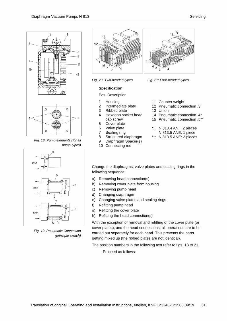
Fig. 20: Two-headed types Fig. 21: Four-headed types
Change the diaphragms, valve plates and sealing rings in the
following sequence:
a) Removing head connection(s)
b) Removing cover plate from housing
c) Removing pump head
d) Changing diaphragm
e) Changing valve plates and sealing rings
f) Refitting pump head
g) Refitting the cover plate
h) Refitting the head connection(s)
With the exception of removal and refitting of the cover plate (or
cover plates), and the head connections, all operations are to be
carried out separately for each head. This prevents the parts
getting mixed up (the ribbed plates are not identical).
The position numbers in the following text refer to figs. 18 to 21.
Proceed as follows:
Fig. 18: Pump elements (for all
pump types)
Fig. 19: Pneumatic Connection
(principle sketch)
Specification
Pos. Description
1 Housing 2 Intermediate plate 3 Ribbed plate 4 Hexagon socket head
cap screw 5 Cover plate 6 Valve plate 7 Sealing ring 8 Structured diaphragm 9 Diaphragm Spacer(s) 10 Connecting rod
11 Counter weight 12 Pneumatic connection .3 13 Union 14 Pneumatic connection .4* 15 Pneumatic connection .5** *: N 813.4 AN_: 2 pieces
N 813.5 ANE: 1 piece **: N 813.5 ANE: 2 pieces

Servicing Diaphragm Vacuum Pumps N 813
32 Translation of original Operating and Installation Instructions, english, KNF 121240-121506 09/19
a) Removing pneumatic head connections (once for all pump heads)
N 813.3 AN__:
5. Remove pneumatic connection (12): Use a 14 mm spanner to
release the unions (13) on each head, and remove the pneu-
matic connection upwards.
N 813.4 AN__:
1. Remove pneumatic connection (12): Use a 14 mm spanner to
release the unions (13) on each head, and remove the pneu-
matic connection upwards.
2. Release both pneumatic connections (14) with a 17 mm open-
ended spanner, and remove them.
N 813.5 ANE:
1. Remove pneumatic connection (12): Use a 14 mm spanner to
release the unions (13) on each head, and remove the pneu-
matic connection upwards.
2. Release both pneumatic connections (14) with a 17 mm open-
ended spanner, and remove them.
3. Open both pneumatic connections (15) with a 17 mm open-
ended spanner, and remove them.
b) Removing cover plate
1. Undo the 4 screws and remove the cover plate (5) from hous-
ing (1) (N 813.3 AN__: 1 cover plate; N 813.4 AN__, and
N 813.5 ANE: each two cover plates).
c) Removing the pump head (for each head separately)
1. Make a mark (M) on the ribbed plate (3), intermediate plate (2),
and housing (1) with a felt-tip pen. This helps avoid incorrect
assembly later.
2. Undo the 4 screws (4) in the ribbed plate and lift the ribbed
plate with the intermediate plate off the pump housing.
d) Changing diaphragms
1. Turn the counter weight (11) to bring the structured diaphragm
(8) to top dead centre.
2. Lift the edge of the diaphragm and, gripping it on opposite
sides, unscrew it by turning anti-clock-wise.
3. Take the diaphragm spacer(s) (9) off the threaded portion of
the structured diaphragm and put them on the thread of the
new structured diaphragm (8).
4. Check that all parts are free from dirt and clean them if neces-
sary (see section 6. Cleaning).
5. Turn the counter weight (11) until the connecting rod (10) is at
the top dead centre.

Diaphragm Vacuum Pumps N 813 Servicing
Translation of original Operating and Installation Instructions, english, KNF 121240-121506 09/19 33
6. Screw the structured diaphragm, complete with diaphragm
spacer(s), into the connecting rod (clockwise) and tighten it by
hand.
e) Changing valve plates and sealing rings
1. Separate the ribbed plate (3) from intermediate plate (2).
2. Remove the valve plates (6) and sealing rings (7) from the
intermediate plate.
3. Check that the valve seats, the ribbed plate and intermediate
plate are clean. If scratches, distortion, or corrosion are evident
on these parts they should be replaced.
4. Lay the new valve plates in the recesses in the intermediate
plate. The valve plates for suction and pressure sides are iden-
tical, as are upper and lower sides of the plates.
5. Check that the valve plates are not deformed by moving them
gently sideways in their recesses.
6. Lay the sealing rings on the intermediate plate.
f) Refitting the pump heads
1. Turn the counter weight (11) to bring the structured diaphragm
(8) to top dead centre.
2. Place the intermediate plate (2), with valve plates (6) and
sealing rings (7), and ribbed plate (3) on the housing, in the
position indicated by the markings (M).
3. Gently tighten the screws (4), evenly and diagonally.
4. Turn the counter weight to check that the pump rotates freely.
5. Now tighten screws (4) firmly.
Repeat operations c), d), e), and f) for the remaining pump head
(or heads).
g) Refitting the cover plate
1. Refit the cover plate (5) to housing (1).
h) Refitting the pneumatic head connection(s)
1. Refit the pneumatic head connection(s).
If you have any questions about servicing, call your KNF technical
adviser (see last page for contact telephone number).

Troubleshooting Diaphragm Vacuum Pumps N 813
34 Translation of original Operating and Installation Instructions, english, KNF 121240-121506 09/19
9. Troubleshooting
DANGER
Risk of electric shock, danger of death! Disconnect the pump power supply before working
on the pump.
Make sure the pump is de-energized and secure.
Check the pump (see Tab. 14 and 15).
Pump does not work
Cause Fault remedy
Pump not connected to the mains.
Connect pump to the mains.
No voltage in the mains. Check room fuse and switch on if necessary.
For pumps with brushless DC motor:
The motor board’s overcur-
rent protection circuit has
activated.
Maximum temperature of
motor board is exceeded
Maximum blocking time of
the rotor is exceeded
Separate pump from the mains.
Determine and remove the cause of the overcurrent (for example: improper pressure, liquid in the pump heads).
The pump must be separated from the mains for several seconds before the electronics will permit restarting.
For pumps with brushless DC motor: Wrong polarity of the connection wires
Separate pump from the mains.
Be aware of right polarity of the connection wires and connect pump.
For pumps with AC motor: The pump's thermal switch has triggered.
Disconnect pump from the mains.
Allow pump to cool.
Identify and eliminate cause of overheating.
Connections or hoses are blocked.
Check hoses and connections.
Remove blockage.
External valve is closed or filter is clogged.
Check external valves and filters.
Condensate has collected in the pump head.
Detach the condensate source from the pump.
Flush the pump (see Chapter 8.2.1).
Install the pump at the highest point in the system.
Diaphragm or valve plates are worn.
Replace diaphragm and valve plates (see Chapter 8.3).
Tab. 14

Diaphragm Vacuum Pumps N 813 Troubleshooting
Translation of original Operating and Installation Instructions, english, KNF 121240-121506 09/19 35
Flow rate, pressure, or vacuum are too low
The pump does not achieve the performance stated in the technical data or on the data sheet.
Cause Fault remedy
Condensate has collected in the pump head.
Detach the condensate source from the pump.
Flush the pump (see Chapter 8.2.1).
Install the pump at the highest point in the system.
Presence of positive pressure on the pressure side with simul-taneous vacuum or positive pressure on the suction side.
Change the pressure conditions.
Cross-section of pneumatic hoses or connectors too narrow or restricted.
Disconnect the pump from the system and determine output values.
Remove restriction (e.g. valve) if necessary.
If applicable, use larger-diameter hoses or connectors.
Leaks in connections, hoses or pump head.
Make sure the hoses are properly seated on the hose connectors.
Replace leaking hoses.
Eliminate leaks.
Connections or hoses complete-ly or partially clogged.
Check hoses and connections.
Remove any parts or particles causing blockages.
Pump head components are soiled.
Clean head components.
Diaphragm or valve plates are worn.
Replace diaphragm and valve plates (see Chapter 8.3).
Diaphragm and valve plates have been replaced.
Make sure that the shim rings have been replaced onto the diaphragm screw thread.
Check head connection and hose connections for leaks. Tab. 15

Troubleshooting Diaphragm Vacuum Pumps N 813
36 Translation of original Operating and Installation Instructions, english, KNF 121240-121506 09/19
Fault visualization on motor controller (for pumps with brushless DC motor)
The excess of the overcurrent limit, the excess of the maximum
temperature of the motor board or the blocking of the rotor is
shown as a fault. A red LED on the BLDC motor controller signals
the cause of the fault.
Optional setting:
If desired, the motor controller can be programmed so that the
error output voltage exhibits the same characteristics as the LED.
With factory settings, only 1 or 0 are logically outputted as voltage
at the fault output.
Fig. 22: LED blinking duration according to different faults
To delete the error condition the motor has to be disconnected
from the mains.
Fault cannot be rectified
If you are unable to identify the cause of the problem, please send
the pump to KNF customer services (see last page for the ad-
dress).
1. Flush the pump (see Chapter 8.2.1).
2. Clean the pump (see Chapter 8.2.2).
3. Send the pump, together with completed Health and Safety
Clearance and Decontamination Form, to KNF stating the na-
ture of the transferred medium.
Diaphragm Vacuum Pumps N 813 Spare parts and accessories
Translation of original Operating and Installation Instructions, english, KNF 121240-121506 09/19 37
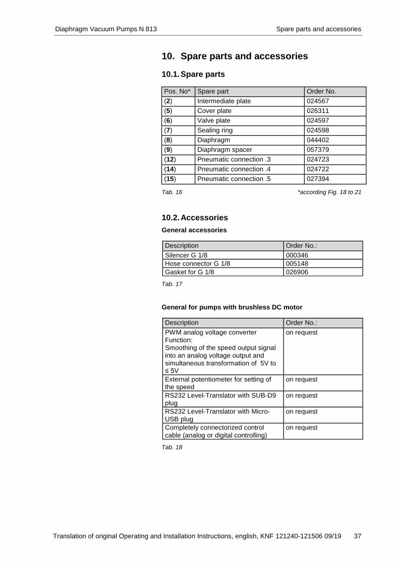
10. Spare parts and accessories
10.1. Spare parts Pos. No* Spare part Order No.
(2) Intermediate plate 024567
(5) Cover plate 026311
(6) Valve plate 024597
(7) Sealing ring 024598
(8) Diaphragm 044402
(9) Diaphragm spacer 057379
(12) Pneumatic connection .3 024723
(14) Pneumatic connection .4 024722
(15) Pneumatic connection .5 027394 Tab. 16 *according Fig. 18 to 21
10.2. Accessories
General accessories
Tab. 17
General for pumps with brushless DC motor
Tab. 18
Description Order No.:
Silencer G 1/8 000346
Hose connector G 1/8 005148
Gasket for G 1/8 026906
Description Order No.:
PWM analog voltage converter Function: Smoothing of the speed output signal into an analog voltage output and simultaneous transformation of 5V to ≤ 5V
on request
External potentiometer for setting of the speed
on request
RS232 Level-Translator with SUB-D9 plug
on request
RS232 Level-Translator with Micro-USB plug
on request
Completely connectorized control cable (analog or digital controlling)
on request

Returns Diaphragm Vacuum Pumps N 813
38 Translation of original Operating and Installation Instructions, english, KNF 121240-121506 09/19
11. Returns
Prerequisite for repairing a pump by KNF is a completed Decon-
tamination Form.
This is made available on the KNF website as a download. To find
the form, select your country on the overview page (www.knf.com).
You can find the Decontamination Form in the download area.
If you have questions, please contact your sales partner (contact
data: see www.knf.com).

KNF worldwide Find your local KNF partner on www.knf.com