Embed Size (px)
Citation preview
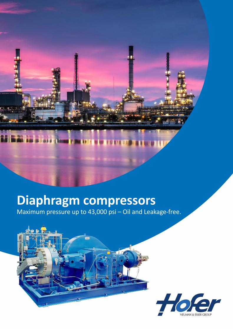
Diaphragm compressorsMaximum pressure up to 43,000 psi – Oil and Leakage-free.
HOFER diaphragm compressors are hermetically sealed towards the outside. Static sealings guarantee a contamination-freecompression of different gases, such as nitrogen, hydrogen, helium, argon, ethylene, fluorine, hydrosulphide, chlorine gas, monosilan, NF3, etc. as well as for gas mixtures. As per HOFER standard the tightness is 145 psi l/s, in special design up to 14,500 psi l/s.
Diaphragm compressors are especially suitable for toxic and hazardous gases for saving the environment and protecting the health. High purity gases can be processed without any contamination or losses.
Constructional features
Depending on the operating data, HOFER diaphragm compressors will be manufactured in 1- to 4-stage design with one crank drive. Each diaphragm head is equipped with metal triple diaphragms and diaphragm failure indicator. Multi-stage machines are generally designed for foundation-free installation, i.e. they are nearly free of dynamic forces. 1-stage compressors can also be supplied with mass compensation for foundation-free installation.
As per standard, the design of the compressors will be in accordance with the harmonized European safety regulations for machinery, the ATEX regulations and the pressure equipment directive (PED) and thus, will be CE-marked.
Function and operational characteristics
The gas is compressed in a double concave chamber by an oscillating sandwich diaphragm which is hydraulically set into motion from one side. The diaphragm ”seals and separates” the gas chamber hermetically against the drive unit. At the periphery, it is clamped between diaphragm cover and flange with perforated plate and is set into oscillating motion by the hydraulic pressure.
The displacement of the plates causes the gas chamber between the diaphragm plate and the diaphragm cover to be enlarged or reduced with every cycle.
When the compression cycle begins, the process gas enters through the suction valve. As the cycle continues, the available volume in the compression chamber is reduced and the gas rea-ches its target pressure and moves through the discharge valve.
The oil pressure, which is required for this bending movement of the diaphragm plates, is generated from the crankcase by the piston moving to and fro. The displacement of the piston and the diaphragm head are nearly equal.
With the compression stroke the piston presses the hydraulic oil into the diaphragm head and there through the perforated plate to the rear side of the diaphragm head. Hereby the diaphragm is bent against the concave surface of the cover. In its return movement, the piston draws the diaphragm back against the also concave surface of the perforated plate.
Diaphragm compressors
Combined Compressors
Since diaphragm compressors have limited suction capacity and non-lubricated piston compressors have a limited discharge pressure, HOFER offers a combined compressor type, which realizes the advantages of each type with one crank drive. The pre-compression is done oil-free in the non-lubricated piston stages and the high-pressure compression in the final diaphragm stage.
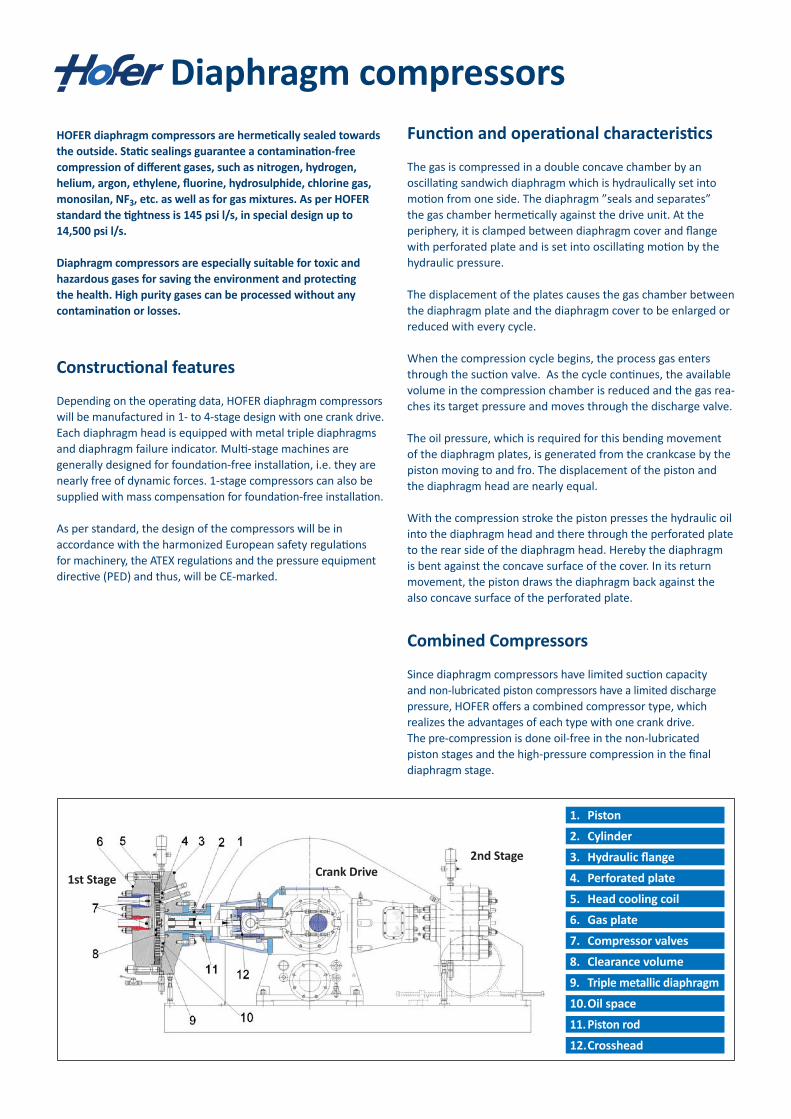
1. Piston
2. Cylinder
3. Hydraulic flange
4. Perforated plate
5. Head cooling coil
6. Gas plate
7. Compressor valves
8. Clearance volume
9. Triple metallic diaphragm
10. Oil space
11. Piston rod
12. Crosshead
1st Stage
2nd StageCrank Drive

© Andreas Hofer Hochdrucktechnik GmbH 03.07technical modifications reserved
Combined CompressorsSince diaphragm compressors have limited suctioncapacity and non-lubricated piston compressors have alimited discharge pressure, HOFER offers a combinedcompressor type, which realizes the advantages of eachtype with one crank drive.The pre-compression is done oil-free in the non-lubricatedpiston stages and the high-pressure compression in thefinal diaphragm stage (see opposite photo).
HOFER high pressure valvesDN 2 to DN 25, 3.625 psi (PN 250 bar) to 145.000 psi (PN10.000 bar); manuell-operated or pneumatically operated,closing or opening by spring force.
Serving IndustryHOFER compressors are used in nearly every industry inwhich high-purity, rare, or hazardous gases are utilized.Some specific applications are:
PTA plants (prod. of terephthalic acid)Gas cylinder filling, gas blending and mixing systemsChemical, pharmaceutical and petrochemical plantsGas transfer, filling and off-loading of tube trailersGases for electronics, semiconductor and fiber opticsmanufacturingHydrogen filling stationsResearch and developmentPressure boosting and high-pressure gas storage-systemsSpace centers
Andreas Hofer Hochdrucktechnik GmbH
Ruhrorter Strasse 45D-45478 Mülheim an der RuhrGermany
Phone +49-(0)208-46 99 6- 0Fax +49-(0)208-46 99 6-11Web www.andreas-hofer.deE-mail [email protected]
2-stage dry running piston compressor with final diaphragm stageModel: 120TK500 / MKZ 350-40
Capacity: 295 scfm (~500 Nm3/h)Suction pressure: 232 psi (16 bar)
Discharge pressure: 4.350 psi (300 bar)
DiaphragmCompressors
PistonCompressors
PressurizingSystems
ValvesFittings
Hofer-Service
certified toISO 9001
by TÜV CERT
certified toPED Module Hby TÜV CERT
Further HOFER products
Diaphragm compressorsHOFER diaphragm compressors are hermetically sealedtowards the outside.Static sealings guarantee a contamination-free compressionof different gases, such as e.g. nitrogen, hydrogen, helium,argon, ethylene, fluorine, hydrosulphide, chlorine gas,monosilan, NF3, etc. as well as for gas mixtures.As per HOFER standard the tightness is 10-4 mbar l/s, inspecial design up to 10-6 mbar l/s.Diaphragm compressors are especially suitable for toxicand hazardous gases for saving the environment andprotecting the health.High purity gases can be proceed without any contaminationor losses.
Constructional featuresDepending on the operating data, HOFER diaphragmcompressors will be manufactured in 1- to 4-stage designwith one crank drive. Each diaphragm head is equippedwith metal triple diaphragms and diaphragm failureindicator. Multi-stage machines are generally designedfor foundation-free installation, i.e. they do almost nothave any free dynamic forces. 1-stage compressors canalso be supplied with mass compensation for foundation-free installation.
The water cooling does not only enclose the gas coolersand cylinders, but also the diaphragm head on thehydraulic side.
There are no additional cooling water bores in thediaphragm cover. Thus, the high-loaded diaphragmhead is not weakened.
HOFER does not only manufacture compressors, but alsovalves (shutoff-, nonreturn- safety valves and connectingelements) and thus, HOFER can complete the valve panelswith their own products (bellows-sealed valves included).
Design, engineering and manufacturing are in onehand at HOFER. By that, maintenance and repair workcan be carried out easily.
Tailor-made and customized solutions by HOFER offeroptimal advantages to our customers.
Each compressor is optimized and designed for therequired technical parameter.
The horizontal design of the HOFER compressors allowsto arrange the oil overflow valves at the highest point ofthe diaphragm head.
Only by that, a quick and reliable venting can be done.HOFER compressors are engineered in crosshead designfor continuous operation.
No lateral forces on the piston guiding rings and sealingrings occur.
As per standard, the design of the compressors will bein accordance with the harmonized European safetyregulations for machinery, the ATEX regulations and thepressure equipment directive (PED) and thus, will be CE-marked.
3-stage diaphragm compressor with digital oil-pressureindication display and oil-pressure supervision
Model: MKZ 280-10/185-20/120-100 for Helium serviceCapacity: 12 scfm (~20 Nm3/h)
Suction pressure: 116 psi (8 bar)Discharge pressure: 12.760 psi (880 bar)
Piston
Cylinder
Hydraulic flange
Perforated plate
Head cooling coil
Gas plate
Compressor valves
Clearance volume
Triple metallic diaphragm
Oilspace
Piston rod
Crosshead
1.
2.
3.
4.
5.
6.
7.
8.
9.
10.
11.
12.
Advantages of HOFER diaphragm compressors
HOFER Diaphragm compressorsAdvantages of HOFER diaphragm compressors
The water cooling does not only enclose the gas coolers and cylinders, but also the diaphragm head on the hydraulic side.
Therearenoadditionalcoolingwaterboresinthe diaphragmcover.Thus,thehigh-loadeddiaphragm headisnotweakened.
HOFER does not only manufacture compressors, but also valves (shut-off, non-return safety valves and connecting elements) and thus, HOFER can complete the valve panels with their own products (bellows-sealed valves included).
Design,engineeringandmanufacturingareinonehand atHOFER.Hence,maintenanceandrepairworkcanbe carriedouteasily.
Tailor-made and customized solutions by HOFER offer optimal advantages to our customers.
Eachcompressorisoptimizedanddesignedforthe requiredtechnicalparameter.
The horizontal design of the HOFER compressors allows to arrange the oil overflow valves at the highest point of the diaphragm head.
Onlybythat,aquickandreliableventingcanbedone. HOFERcompressorsareengineeredincrossheaddesign forcontinuousoperation.
Nolateralforcesonthepistonguidingringsandsealing ringsoccur.
Low piston velocities as well as low specific loads on the bearings guarantee a high life length of the wear parts.
TherearenolateralforcesatthepistonofHOFER compressorswhicharecausedbyconversionofangular movementofthecrankshaftintolinearmovement.
The special design of HOFER`s crank drives gives the opportunity to combine a dry-running piston compressor and a diaphragm compressor.
Noadditionalinvestmentforasecondcompressor isrequired.
TheadvantagesofaHOFERdiaphragmcompressor remainalsoathighersuctioncapacities.
Wear and spare parts for HOFER compressors are available for a life span of min. 30 years. This guarantees decades of using HOFER products.
Wearandsparepartsarealwaysonthelatestlevel oftechnology.
The HOFER compressors with mass compensation do almost not have any free dynamic forces.
Foundationsarenolongerrequired.Asolidfoundation plateissuitable.
Low piston velocities as well as low specific loads on thebearings guarantee a high life length of the wear parts.
There are no lateral forces at the piston of HOFERcompressors which are caused by conversion of angularmovement of the crankshaft into linear movement.
The special design of HOFER`s crank drives gives theopportunity to combine a dry-running piston compressorand a diaphragm compressor.
No additional investment for a second compressor isrequired.The advantages of a HOFER diaphragm compressorremain also at higher suction capacities.
Wear and spare parts for HOFER compressors are availablefor a life span of min. 30 years. This guarantees decadesof using HOFER products.
Wear and spare parts are always on the latest level oftechnology.
The HOFER compressors with mass compensation doalmost not have any free dynamic forces.
Foundations are no longer required. A good bearingbottom plate is suitable. With the beginning of the enlarging of the gas space, the
gas is sucked in from the suction tube via the suctionvalve, which is installed in the cover and with reducingthe gas space, the gas is compressed through thedischarge valve – also installed in the cover – intothe discharge tube.The oil pressure, which is required for this bendingmovement of the diaphragm plates, is generated fromthe crankcase by the piston moving to and fro. The pistondisplacement nearly equals to the displacement insidethe diaphragm head.With the compression stroke the piston presses thehydraulic oil into the diaphragm head and there throughthe perforated plate to the rear side of the diaphragmhead. Hereby the diaphragm is bent against the concavesurface of the cover. In its return movement, the pistondraws the diaphragm back against the also concavesurface of the perforated plate.
2-stage diaphragm compressorModel: MKZ 680-10/450-40 for
hydrogen serviceCapacity: 342 scfm (~580 Nm3/h)
Suction pressure: 261 psi (18 bar)Discharge pressure: 4.060 psi (280 bar)
Function and operational characteristicsThe gas is compressed in a double concave chamber byan oscillating sandwich diaphragm, which is hydraulicallyset into motion from one side. The diaphragm seals andseparates the gas chamber hermetically against the driveunit. At the periphery, it is clamped between diaphragmcover and flange with perforated plate and is set intooscillating motion by the hydraulic pressure.The displacement of the plates causes the gas chamberbetween the diaphragm plate and the diaphragm cover tobe enlarged respectively reduced with every cycle.
Single-stage diaphragm compressorModel: MKZ 400-5
Capacity: 74 scfm (~125 Nm3/h)Suction pressure: 203 psi (14 bar)
Discharge pressure: 450 psi (31 bar)
Type MKZ up to 43.500 psi (3.000 bar)
3-stage diaphragm compressor with digital oil-pressure indication display and oil-pressure supervisionModel: MKZ 280-10/185-20/120-100 for Helium serviceCapacity: 12 scfm (~20 Nm3/h)Suction pressure: 116 psi (8 bar)Discharge pressure: 12,760 psi (880 bar)
2-stage diaphragm compressorModel: MKZ 680-10/450-40 for hydrogen serviceCapacity: 342 scfm (~580 Nm3/h)Suction pressure: 261 psi (18 bar)Discharge pressure: 4,060 psi (280 bar)
2-stage dry-running piston compressor with final diaphragm stageModel: 120TK500 / MKZ 350-40Capacity: 295 scfm (~500 Nm3/h)Suction pressure: 232 psi (16 bar)Discharge pressure: 4,350 psi (300 bar)
Low piston velocities as well as low specific loads on thebearings guarantee a high life length of the wear parts.
There are no lateral forces at the piston of HOFERcompressors which are caused by conversion of angularmovement of the crankshaft into linear movement.
The special design of HOFER`s crank drives gives theopportunity to combine a dry-running piston compressorand a diaphragm compressor.
No additional investment for a second compressor isrequired.The advantages of a HOFER diaphragm compressorremain also at higher suction capacities.
Wear and spare parts for HOFER compressors are availablefor a life span of min. 30 years. This guarantees decadesof using HOFER products.
Wear and spare parts are always on the latest level oftechnology.
The HOFER compressors with mass compensation doalmost not have any free dynamic forces.
Foundations are no longer required. A good bearingbottom plate is suitable. With the beginning of the enlarging of the gas space, the
gas is sucked in from the suction tube via the suctionvalve, which is installed in the cover and with reducingthe gas space, the gas is compressed through thedischarge valve – also installed in the cover – intothe discharge tube.The oil pressure, which is required for this bendingmovement of the diaphragm plates, is generated fromthe crankcase by the piston moving to and fro. The pistondisplacement nearly equals to the displacement insidethe diaphragm head.With the compression stroke the piston presses thehydraulic oil into the diaphragm head and there throughthe perforated plate to the rear side of the diaphragmhead. Hereby the diaphragm is bent against the concavesurface of the cover. In its return movement, the pistondraws the diaphragm back against the also concavesurface of the perforated plate.
2-stage diaphragm compressorModel: MKZ 680-10/450-40 for
hydrogen serviceCapacity: 342 scfm (~580 Nm3/h)
Suction pressure: 261 psi (18 bar)Discharge pressure: 4.060 psi (280 bar)
Function and operational characteristicsThe gas is compressed in a double concave chamber byan oscillating sandwich diaphragm, which is hydraulicallyset into motion from one side. The diaphragm seals andseparates the gas chamber hermetically against the driveunit. At the periphery, it is clamped between diaphragmcover and flange with perforated plate and is set intooscillating motion by the hydraulic pressure.The displacement of the plates causes the gas chamberbetween the diaphragm plate and the diaphragm cover tobe enlarged respectively reduced with every cycle.
Single-stage diaphragm compressorModel: MKZ 400-5
Capacity: 74 scfm (~125 Nm3/h)Suction pressure: 203 psi (14 bar)
Discharge pressure: 450 psi (31 bar)
Type MKZ up to 43.500 psi (3.000 bar)
Single-stage diaphragm compressorModel: MKZ 400-5Capacity: 74 scfm (~125 Nm3/h)Suction pressure: 203 psi (14 bar)Discharge pressure: 450 psi (31 bar)

Industries
HOFER compressors are used in nearly every industry in which high-purity, rare, or hazardous gases are utilized.
Some specific applications are:
PTA plants (prod. of terephthalic acid)
Gas cylinder filling, gas blending and mixing systems
Chemical, pharmaceutical and petrochemical plants
Gas transfer, filling and off-loading of tube trailers
Gases for electronics, semiconductor and fiber optics manufacturing
Hydrogen filling stations
Research and development
Pressure boosting and high-pressure gas storage systems
Space centers
Andreas Hofer Hochdrucktechnik GmbH
Ruhrorter Straße 45
D-45478 Mülheim an der Ruhr
Germany
Fon +49-(0)208-4 69 96- 0
Fax +49-(0)208-4 69 96-11
Web www.andreas-hofer.de
Email [email protected]
"Zur Sicherheit – Hofer-Qualität"
HOFER SERVICE DEU 2/2 © by Andreas Hofer GmbH 04.08
www.hofer-highpressure.com
Andreas Hofer Hochdrucktechnik GmbHRuhrorter Straße 45D-45478 Mülheim an der Ruhr
Phone +49 (0) 208 4 69 96 0Fax +49 (0) 208 4 69 96 11e-mail [email protected]