Embed Size (px)
Citation preview

Diameter Configuration
• Diameter Configuration, on page 1• Diameter Stack Configuration, on page 17• Diameter Agents, on page 26• Diameter Clients, on page 29• Diameter Defaults, on page 51• Rule Retry Profiles, on page 71
Diameter ConfigurationThe Diameter Configuration section allows for the configuration of the diameter plug-in. We recommendconfiguring the diameter plug-in at system level.
At System Level
In order to define a Diameter Configuration at system level, you need to perform the following steps:
1. Login into Policy Builder.2. Select Reference Data tab.3. From the left pane, select Systems.4. Select and expand your system name.5. Select Plugin Configurations.6. Select Diameter Configuration.
At Cluster Level
In order to define a Diameter Configuration at cluster level you need to perform the following steps:
1. Log in into Policy Builder.2. Select Reference Data tab.3. From the left pane, select Systems.4. Select and expand your system name.5. Select and expand your cluster name. If no cluster has been created, create one by selecting the Cluster
action.
6. Select Plugin Configurations.7. Select Diameter Configuration.
Diameter Configuration1

The following parameters can be configured under Diameter Configuration.
Table 1: Diameter Configuration Parameters
DescriptionParameter
This timer is armed every time a message is received or sent for any given Gx session.When the timer expires (or more precisely within the next minute after the timerexpires) a Gx RAR having the Re-Auth-Request-Type AVP set toAUTHORIZE_ONLY (0) message is triggered for that Gx session. If a Gx RAA isreceived having Result-Code AVP value set toDIAMETER_UNKNOWN_SESSION_ID (5002) orDIAMETER_UNABLE_TO_COMPLY (5012) the Gx session is deemed as staleand removed from the PCRF internal database. On any activity over Gx interface(RAR/CCR) the timer is reset.
Default value is 180 minutes.
Note • This timer unit is minute.• Stale Gx session removal triggers the PCRF session terminationprocedure for any other diameter sessions that were bound to the Gxsession.
Default Gx StaleSession TimerMinutes
This option allows for a different set of list of valid values and their interpretation tobe used for the Event-Trigger enumerated AVP in order to accommodate the changethat occurred in the Gx specification between 3GPP TS 29.212 v9.5 (and prior) and3GPP TS 29.212 v9.7 (and following including v10 v11 and v12). Default value ischecked.
List of valid values is provided in Table 2: Use V9 Event Trigger Mapping ValidValues, on page 3.
Note • The Event-Trigger AVP list of valid values and their interpretationdefined in 3GPP TS 29.212 v9.6 is not supported.
• Use V9 Event Trigger Mapping checked uses 3GPP TS 29.212 v9.5as a reference while 3GPP TS 29.212 v110.10 is used as a referencewhen not checked.
Use V9 EventTrigger Mapping
This option allows for the Gx usage monitoring feature to be supported even whenthe PCEF advertises support for Rel8 feature under Supported-Features AVP in GxCCR-i.
Default value is checked.
Rel8 UsageMonitoringSupported
When a new row is added in “Stale Session Configuration” table the default value forthe GX_TGPP SD_V11 and SY_V11 Stale session timer is 180 minutes.
The maximum value allowed for the Stale Session Timer parameter is35000 minutes.
Note
If GX_TGPP Stale Session Timer value is not configured in this table, then the valueis selected from the retained/old variable “Default Gx Stale Session Timer Minutes”.
If there are multiple values configured against any interface then the lowest amongall would be considered as the stale session timer.
Stale SessionConfiguration
Diameter Configuration2
Diameter ConfigurationDiameter Configuration

If Gx stale session timer is set for both “Default Gx Stale Session timer Minutes” and “Stale SessionConfiguration” then the value configured Under “Stale Session Configuration” would take the precedence.
Note
Table 2: Use V9 Event Trigger Mapping Valid Values
Interpretation - Use V9 Event TriggerMapping is not checked
ValueInterpretation - Use V9 EventTrigger Mapping is checked
SGSN_CHANGE0SGSN_CHANGE
QOS_CHANGE1QOS_CHANGE
RAT_CHANGE2RAT_CHANGE
TFT_CHANGE3TFT_CHANGE
PLMN_CHANGE4PLMN_CHANGE
LOSS_OF_BEARER5LOSS_OF_BEARER
RECOVERY_OF_BEARER6RECOVERY_OF_BEARER
IP_CAN_CHANGE7IP_CAN_CHANGE
QOS_CHANGE_EXCEEDING
_AUTHORIZATION
11QOS_CHANGE_EXCEEDING
_AUTHORIZATION
RAI_CHANGE12RAI_CHANGE
USER_LOCATION_CHANGE13USER_LOCATION_CHANGE
NO_EVENT_TRIGGERS14NO_EVENT_TRIGGERS
OUT_OF_CREDIT15OUT_OF_CREDIT
REALLOCATION_OF_CREDIT16REALLOCATION_OF_CREDIT
REVALIDATION_TIMEOUT17REVALIDATION_TIMEOUT
UE_IP_ADDRESS_ALLOCATE18UE_IP_ADDRESS_ALLOCATE
UE_IP_ADDRESS_RELEASE19UE_IP_ADDRESS_RELEASE
DEFAULT_EPS_BEARER
_QOS_CHANGE
20DEFAULT_EPS_BEARER
_QOS_CHANGE
AN_GW_CHANGE21AN_GW_CHANGE
SUCCESSFUL_RESOURCE
_ALLOCATION
22SUCCESSFUL_RESOURCE
_ALLOCATION
Diameter Configuration3
Diameter ConfigurationDiameter Configuration

Interpretation - Use V9 Event TriggerMapping is not checked
ValueInterpretation - Use V9 EventTrigger Mapping is checked
RESOURCE_MODIFICATION
_REQUEST
23RESOURCE_MODIFICATION
_REQUEST
PGW_TRACE_CONTROL24PGW_TRACE_CONTROL
UE_TIME_ZONE_CHANGE25UE_TIME_ZONE_CHANGE
TAI_CHANGE26USAGE_REPORT
ECGI_CHANGE27TAI_CHANGE
CHARGING_CORRELATION
_EXCHANGE
28ECGI_CHANGE
APN_AMBR_MODIFICATION
_FAILURE
29CHARGING_CORRELATION
_EXCHANGE
USER_CSG_INFORMATION
_CHANGE
30USER_CSG_INFORMATION
_CHANGE
NA31DEFAULT_EPS_BEARER
_QOS_MODIFICATION_FAILURE
Diameter Configuration4
Diameter ConfigurationDiameter Configuration

Interpretation - Use V9 Event TriggerMapping is not checked
ValueInterpretation - Use V9 EventTrigger Mapping is checked
USAGE_REPORT33NA
DEFAULT_EPS_BEARER
_QOS_MODIFICATION_FAILURE
34
USER_CSG_HYBRID
_SUBSCRIBED_INFORMATION
_CHANGE
35
USER_CSG_HYBRID
_UNSUBSCRIBED
_INFORMATION_CHANGE
36
ROUTING_RULE_CHANGE37
APPLICATION_START39
APPLICATION_STOP40
CS_TO_PS_HANDOVER42
UE_LOCAL_IP_
ADDRESS_CHANGE
43
HENB_LOCAL_IP_
ADDRESS_CHANGE
44
ACCESS_NETWORK_
INFO_REPORT
45
Inbound Message Overload HandlingThis feature provides a mechanism for the OAM (PCRF) protection in case more traffic than can be handledis received. It provides a way to prioritize the incoming messages and selectively process them.
Diameter Configuration5
Diameter ConfigurationInbound Message Overload Handling
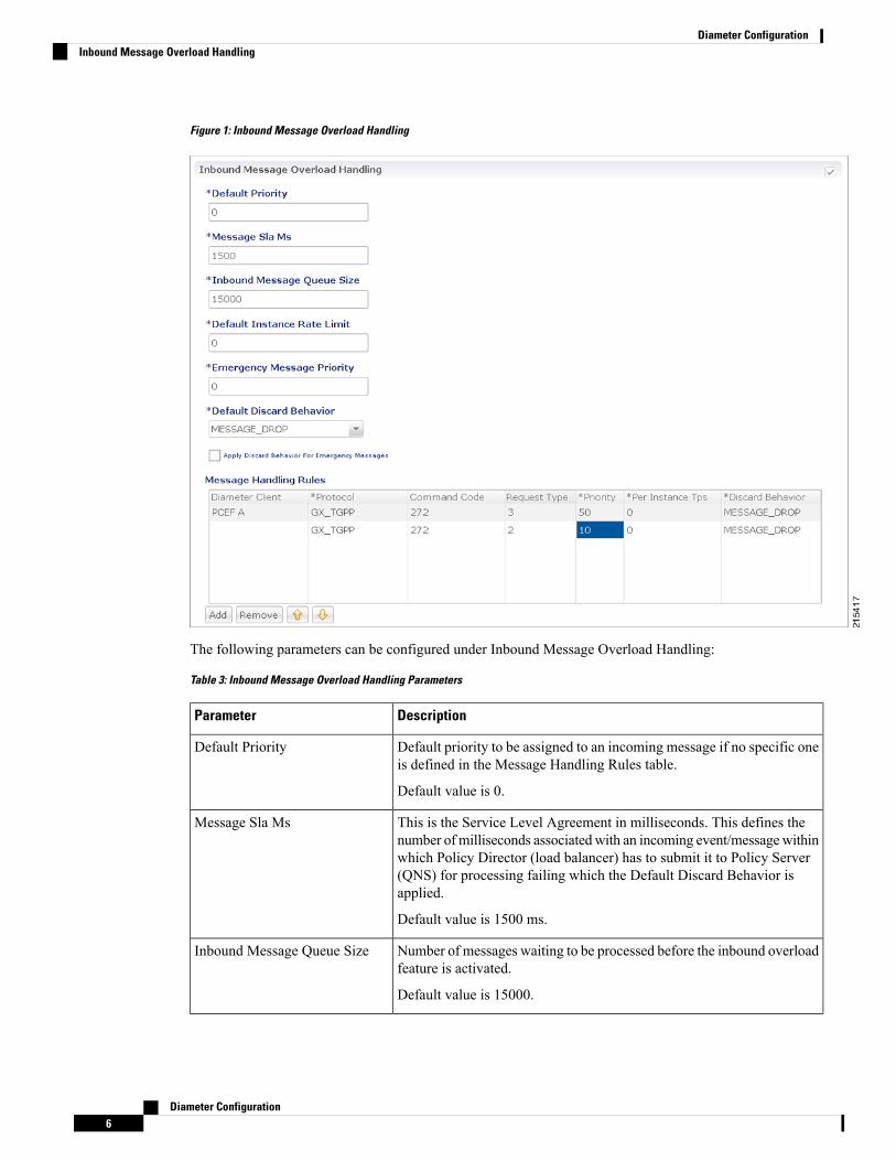
Figure 1: Inbound Message Overload Handling
The following parameters can be configured under Inbound Message Overload Handling:
Table 3: Inbound Message Overload Handling Parameters
DescriptionParameter
Default priority to be assigned to an incoming message if no specific oneis defined in the Message Handling Rules table.
Default value is 0.
Default Priority
This is the Service Level Agreement in milliseconds. This defines thenumber of milliseconds associatedwith an incoming event/messagewithinwhich Policy Director (load balancer) has to submit it to Policy Server(QNS) for processing failing which the Default Discard Behavior isapplied.
Default value is 1500 ms.
Message Sla Ms
Number of messages waiting to be processed before the inbound overloadfeature is activated.
Default value is 15000.
Inbound Message Queue Size
Diameter Configuration6
Diameter ConfigurationInbound Message Overload Handling

DescriptionParameter
This defines the Rate at which incoming messages are staggered beforebeing submitted to the Policy Server.
Default value is 0.
Default Instance Rate Limit
Default priority assigned to messages related to an emergency session.
Default value is 0.
Emergency Message Priority
Default behavior to be applied to an incoming message if no specific oneis defined in the Message Handling Rules table.
• MESSAGE_DROP (default) Silently discards the request.• DIAMETER_TOO_BUSY Sends a response message havingResult-Code AVP value set to DIAMETER_TOO_BUSY (3004)
Default Discard Behavior
Indicates if Emergency Messages can be discarded under overloadconditions.
Default value is not checked.
Apply Discard Behavior ForEmergency Messages
Defines specific inbound message overload handling rules based ondifferent criteria. For more information refer to Table 5:Message HandlingRules Parameters, on page 8.
Message Handling Rules
If Inbound Message Overload Handling check box is not selected in Diameter Configuration, you can defineinboundMessageSlaMs and inboundMessageQueueSize in /etc/broadhop/qns.conf file. For moreinformation refer to Table 4: Message Parameters, on page 7.
Note
Table 4: Message Parameters
DescriptionParameter
This parameter specifies the Service Level Agreement in milliseconds.This defines the number of milliseconds associated with an incomingevent/message within which Policy Director (load balancer) has to submitit to Policy Server for processing failing which the Default DiscardBehavior is applied.
If inboundMessageSlaMs is not defined inqns.conf file then the defaultvalue of 1500 is used.
Example: -DinboundMessageSlaMs=2000
After modifying the configuration on ClusterManager execute reinit.shor copytoall.sh scripts for applying the changes on all VMs as describedin the CPS Installation Guide for VMware for this release.
inboundMessageSlaMs
Diameter Configuration7
Diameter ConfigurationInbound Message Overload Handling

DescriptionParameter
This parameter specified the number of messages waiting to be processedbefore the inbound overload feature is activated.
If inboundMessageQueueSize is not defined in qns.conf file then thedefault value of 15000 is used.
Example: -DinoundMessageQueueSizes=5000
After modifying the configuration on ClusterManager execute reinit.shor copytoall.sh scripts for applying the changes on all VMs as describedin the CPS Installation Guide for VMware for this release.
inboundMessageQueueSize
Table 5: Message Handling Rules Parameters
DescriptionAttributeParameter Type
Diameter client defined under Diameter Clientssection. This field is optional, but is used so thatdifferent clients (based on realms) can havedifferent priorities. For more information, referto Diameter Clients, on page 29.
Diameter ClientINPUT
Specific application id value to be used forscoring. This is to match Auth-Application-IdAVP value. For more information refer to Table6: Protocols, on page 9.
Protocol
Specific command code value to be used forscoring. This is to match the Command-Codefield. These command codes map to differenttypes of Diameter messages (CCR = 272 RAR= 258 etc).
Default value is 0.
Command Code
Specific request type value to be used forscoring. This is to match the value of theCC-Request-Type AVP only for CCRmessages.
• 0 (default) Request Type not used forscoring
• 1 INITIAL_REQUEST (1)• 2 UPDATE_REQUEST (2)• 3 TERMINATION_REQUEST (3)
Request Type
Diameter Configuration8
Diameter ConfigurationInbound Message Overload Handling

DescriptionAttributeParameter Type
Priority value assigned to the message. Highernumerical value will be having higher priority
Default value is 0.
PriorityOUTPUT
Transactions per second limit per process. Thisis the TPS that these messages are limited to.Note that this is per CPS process so if there are20 Policy Server VM's with 1 Policy Server javaprocess the total TPS is this number x 20.
The actual system's transaction per second limitcan be calculated using the following formula
Per Instance Tps x Number of instances per VMx Number of VMs
Default value is 0.
Per Instance Tps
Behavior to be applied to an incoming message.
• MESSAGE_DROP (default) Silentlydiscards the request.
• DIAMETER_TOO_BUSY Sends aresponsemessage having Result-CodeAVPvalue set to DIAMETER_TOO_BUSY(3004)
Discard Behavior
Table 6: Protocols
DescriptionAttribute
Standard Gy application as per 3GPP TS 32.299GY_V8
Custom Gx implementationGX_SCE
Not supportedRF_V10
Not supportedRF_VERIZON
Standard Rx application as per 3GPP TS 29.214RX_TGPP
Standard Sh application as per 3GPP TS 29.329SH_TGPP
Standard Sy application as per 3GPP TS 29.219SY_V11
Custom Gx implementationGX_HUAWEI
Standard Sd application as per 3GPP TS 29.212SD_V11
Standard Gx application as per 3GPP TS 29.212GX_TGPP (default)
Not supportedGXX_TGPP
Diameter Configuration9
Diameter ConfigurationInbound Message Overload Handling

DescriptionAttribute
Custom Gx implementationGX_ALLOT
Local MINE adapterRX_CLIENT
Gy proxy implementation as per RFC 3588GY_V8_PROXY
Gx proxy implementation as per RFC 3588GX_TGPP_PROXY
Sy proxy implementation as per RFC 3588SY_TGPP_PROXY
Sy Proxy from OAM (PCRF) endSY_OCS
Support Gy client functionality with external OCS (ECUR modelonly)
GY_RECHARGE_WALLET
Custom Sy implementation as per RFC 3588SY_PRIME
Rx proxy implementation as per RFC 3588RX_TGPP_PROXY
Next Hop RoutingThis feature provides support for inter-working with a DRA that is not configured in topology hiding mode.This is required because while the DRAwill advertise its own origin host and realm values when the diameterconnection is established all the diameter application messages will feature the actual host's origin host andrealm (i.e. PCEF TDF AF). PCRF needs a way to figure out which particular DRA connection should use inorder to deliver a message to the desired host.
While selecting the peer that is used to deliver the request (with or without using the Next Hop Routes table)load balancing across the peers having the same rating is done. Load balancing starts from the peers havinghighest rating and covers all the peers in a round robin manner. If none is UP load balancing is tried with thepeers having the second highest rating and again covers all the peers in a round robin manner and so on.
Next Hop Routes table is used only for PCRF initiated requests. The response messages for any incomingrequest will always be delivered on the same connection where the request was received or will not be deliveredat all. This is in order to avoid asymmetric routes.
Note
TheDRA should explicitly advertise support for a Diameter application other than Relay. The Relay applicationhaving Application Identifier 0xffffffff is not supported.
The following parameters can be configured under Next Hop Routing table:
Table 7: Next Hop Routing Parameters
DescriptionParameter
DRA realm name as received in Origin-Realm AVP in CER or CEAmessage.
All the next hop realms (Next Hop Realm) should match theOrigin-Realm AVP value in the incoming CER/CEA message.
Note
Next Hop Realm
Diameter Configuration10
Diameter ConfigurationNext Hop Routing

DescriptionParameter
DRA hosts name list as received in Origin-Host AVP in CER or CEAmessage.
All the next hop host names (Next Hop Hosts) should match theOrigin-Host AVP value value in the incoming CER/CEAmessage.
Note
Next Hop Hosts
Diameter application id advertised as being supported by the DRA. Itcontains information that identifies the particular service that the servicesession belongs to.
Application Id
Actual destination realm name pattern as received in Origin-Realm AVPin AAR message. The pattern needs to follow the standard Java regularexpression syntax described here.
Destination Realms Pattern
Actual destination host name pattern as received in Origin-Host AVP inAAR message. The pattern needs to follow standard Java patternconventions. The pattern needs to follow the standard Java regularexpression syntax described here.
Destination Host Pattern
While populating the Next Hop Routes table, we recommend that you create only one entry for each NextHop Realm value - Application Id value pair while all the DRA host names are provided as a list under NextHop Hosts field. This is not a requirement though.
• The order in which the routes are provisioned in the Next Hop Routes table is relevant. While lookingfor a DRA connection that could be used to deliver a particular message the table is checked top tobottom.
• The order in which the DRA hosts are provisioned in the Next Hop Hosts field for any given next hoproute is not relevant. The DRA host having the highest rating (priority) value will be used. In case multiplehosts have the same rating one will be randomly selected. Refer to Diameter Stack Configuration, onpage 17 for more details about host rating.
Note
CPS supports grouping of realms and application identifiers using wildcarding and assigns it to a group ofnext hop peers. CPS routes outgoing messages by selecting the peer with highest priority.
An example configuration for Grouping and Wildcarding in the Next Hop Routing table is shown below:
Diameter Configuration11
Diameter ConfigurationNext Hop Routing

Figure 2: Grouping and Wildcarding in the Next Hop Routing Table
Destination Realm andDestination Hosts are used tomapwith the Peer configuration as defined in the DiameterStack. The figure given below shows the mapping of the message containing the Realm from a peer to aprotocol or interface. For more information on peer configuration refer to Diameter Stack Configuration, onpage 17.Figure 3: Rating
Diameter Configuration12
Diameter ConfigurationNext Hop Routing

Message Timeout and Retry ConfigurationMessage Timeout and Retry Configuration table can be configured under Diameter Configuration plug-in inPolicy Builder.
This table allows for the configuration of different message timeout value and retry behavior using thecombination of Application Id, Command Code and (experimental) result code parameters.
Sh Interface (Auth-Application-Id 16777217) message retry information can be configured using:
• Message Timeout and Retry Configuration table
• Setting Up Additional Profile Data
Only one of the two retry configuration options should be used for Sh Interface.
Note
The following parameters can be configured in the Message Timeouts and Retry Configuration table.
Table 8: Message Timeout and Retry Configuration Parameters
DescriptionParameter
The Diameter Application ID (Auth-Application-Id) on the message which isto be retired.
Default: 0
Application Id
The Diameter command code of the message which is to be retried.
Default: 0
Command Code
This is the result code received in the diameter response for which the user wantsto retry. The values configured should be a valid diameter result code value oran experimental result code value. For example, 3002(DIAMETER_UNABLE_TO_DELIVER) received in RAA.
Permanent failure result codes 5xxx and successful result codes 2xxx should notbe configured (where, x denotes a valid number).
However, if configured CPS, will retry for it.
For retry on timeout, the result code should be configured as 7000.Note
Default: 0
Result Code
If this check-box is selected, it means that the value configured in the ResultCode column is an Experimental-Result-Code value.
This is necessary because there are few values which are the same for bothexperimental-result-code and result-code.
Default: Not selected
Is Experimental
Diameter Configuration13
Diameter ConfigurationMessage Timeout and Retry Configuration

DescriptionParameter
The action for the CPS platform to take after the Diameter Response is received.The options are Retry or None.
• Retry - CPS will retry the request message identified by the value in thecommand code column depending on the retry count configured in RetryCount column.
• None - No retry.
Default: None
Action
The amount of time in milliseconds for CPS to wait before retry.
For more information, refer to 1.
Default: 0
Action Timer (Ms)
The number of times to retry when the action is “Retry”.
This retry count does not include the initial attempt made by CPS.Note
Default: 1
Retry Count
Configures CPS to retry on any alternate peer configured in Policy Builder.
Default: Not selected
Retry on Alternate
The back-off algorithm used while determining the actual delay between retryattempts. Currently, only one option (CONSTANT_INTERVAL) is supported.
• LINEAR_INTERVAL: Causes the configured retry interval to increaselinearity with each attempt using the formula retry interval = Action Timer(Ms) x current retry attempt number.
For example, Action=Retry, Action Timer (Ms)=200, Retry Count=3,Backoff Algorithmm=LINEAR_INTERVAL will trigger the first retryafter 200 x 1 = 200 ms, the second retry after 200x2 = 400 ms, the thirdretry after 200x3 = 600ms
• CONSTANT_INTERVAL: Causes the configured retry interval to be used(without any change) for delay for all retry attempts (other options likeexponential back-off where retry interval increases exponentially arecurrently not supported/implemented).
Default: CONSTANT_INTERVAL
Backoff Algorithm
1 If the timeout and retry count is not configured than the default values (diameter.default.timeout.msand diameter.default.retry.count) defined in /etc/broadhop/qns.conf are used.
The diameter.default.timeout.ms and diameter.default.retry.count parameters configured inqns.conf file are taken into consideration only in case of timeout (result code = 7000) and do notimpact the behavior in any other case (result code other than 7000).
If no values are defined in the qns.conf file than the default values ofdiameter.default.timeout.ms=3000 and diameter.default.retry.count=1 are used. If Result Code
Diameter Configuration14
Diameter ConfigurationMessage Timeout and Retry Configuration

= 7000 is defined in theMessage and Retry Configuration table in Policy Builder, than this configurationtakes precedence over qns.conf file parameters.
Result Code Based Action ConfigurationCPS can be configured to take specific action over Gx and Sy based on response received on Sy/Sd interfaces.CPS can be configured to continue (default) terminate or re-initiate the session.Figure 4: Result Code Based Action
The following parameters can be configured in the Result Code Based Action Configuration table.
Table 9: Result Code Based Action Configuration
DescriptionParameter
The diameter interface in numeric format (Auth-Application-Id) on which themessage is received. For example Sy (16777302) and Sd (16777303).
Currently only Sd and Sy interfaces are supported.
Default: 0
Application Id
The diameter message type. For example SLR (8388635) in case of Sy and RAR(258) in case of Sd.
Default: 0
Command Code
The request type of themessage for Sy interface. For example INITIAL_REQUEST(0) INTERMEDIATE_REQUEST (1). For Sd Request Type is not valid.
Default: 0
Request Type
The result-code received in the response for which the action over Gx and/or Sy/Sdis to be taken.
Default: 0
Result Code
Diameter Configuration15
Diameter ConfigurationResult Code Based Action Configuration

DescriptionParameter
If this check-box is selected, it means that the value configured in the Result Codecolumn is an Experimental-Result-Code value.
This is necessary because there are few values which are the same for bothexperimental-result-code and result-code.
Default: Not selected
Is Experimental
The action to be taken over the Sy/Sd interface when the response is received.Possible actions are Continue/Terminate/Reinitiate.
• Continue (default) In case of Continue CPS just continues with the sessionand does not clear the session from the DB.
• Terminate (for Sd) In case of Terminate CPS removes the session fromdatabase after triggering a Session Removal RAR over Sd interface.
Terminate (for Sy) In case of Terminate CPS removes the session fromdatabase after triggering a Session Removal STR over Sy interface.
• Reinitiate (for Sd) In case of Reinitiate CPS first triggers a Session RemovalRAR over Sd interface. Once we receive Sd RAR response (any result-code)CPS removes the old session and triggers creation of a new session by sendingout a TSR towards TDF.
Reinitiate (for Sy) In case of Reinitiate CPS first triggers a Session RemovalSTR over Sy interface. Once we receive Sy STR response (any result-code)CPS removes the old session and triggers creation of a new session by sendingout SLR towards OCS.
Action
Diameter Configuration16
Diameter ConfigurationResult Code Based Action Configuration

DescriptionParameter
The action to be taken over the Gx interface when the response is received. Possibleactions are None/Terminate/Reauthorize.
Currently Action over Gx is not supported for Sd RAR.
• None (default) No action would be taken on Gx interface.• Terminate In case of Terminate CPS would terminate the Gx session bysending a RAR with Session Release Cause. Also CPS would be sendingSTR which would then clear the corresponding Sy device session. If theaction over Gx is TERMINATE the action over Sy does not matter as the Sysession would be terminated.
• Reauthorize In case of Reauthorize CPSwouldmark the Sy session as waitingfor action over Gx and would mark corresponding Gx session as needingaction over Gx as Re-Auth.
The Gx Network Device Manager would then perform the ReAuthorization bysending RAR over Gx interface. On receiving RAA the action over Sy interfacewould then be performed. If the Gx session is stale and we receiveDIAMTER_UNKNOWN_SESSION_ID the Sy session would then beautomatically terminated irrespective of the action configured on Sy interface.
The actions TERMINATE and REAUTHORIZE over Gx does notwork with SLA-Initial if the SLR is sent synchronously. In case theSLR is triggered synchronously and the action over Gx is configuredas TERMINATE/REAUTH the CPS would log an error message andwould continue the session. The synchronous/asynchronous sendingof SLR can be configured in the SpendingLimitReport serviceconfiguration.
Note
Action Over Gx
Diameter Stack ConfigurationThis section allows for the creation of the stacks that will handle the diameter traffic. Depending on yourparticular requirements one or more stacks can be created.
At System Level
In order to define a Diameter stack at system level you need to perform the following steps:
1. Login into Policy Builder.2. Select Reference Data tab.3. From the left pane, select Systems.4. Select and expand your system name.5. Select and expand Plugin Configurations.6. Select Diameter Configuration.7. From the right pane, click Diameter Stack under Create Child.
At Cluster Level
In order to define a Diameter stack at cluster level you need to perform the following steps:
Diameter Configuration17
Diameter ConfigurationDiameter Stack Configuration

1. Login into Policy Builder.2. Select Reference Data tab.3. From the left pane, select Systems.4. Select and expand your system name.5. Select and expand your cluster name.
6. Select and expand Plugin Configurations.7. Select Diameter Configuration.8. From the right pane, click Diameter Stack under Create Child.
The following parameters can be configured under Diameter Stack:
Table 10: Diameter Stack Parameters
DescriptionParameter
Local stack name. This is only used within the Policy Builder GUI to identifythe diameter stack.
Name
Local realm for the diameter stack. This value is going to set as Origin-RealmAVP value in all the diameter messages originated from this stack.
Realm
This allows for any incoming diameter peer connection request to be acceptedby the stack provided the peer realm is provisioned under inbound realms.For more details on Inbound Peers check Inbound Peers, on page 22.
Default value is checked.
If this is unchecked, then the Inbound Peers and Outbound Peerstable must be defined. Note that using this option opens a securityhole into the system. Therefore, Cisco does not recommend usingthis option (uncheck the flag) in production environments.
Note
Accept Undefined Peer
This configures other stack parameters.Local End Points
The host local name where this stack is going to be created.
If Local Host Name value does not map to a valid IP the stack willbind to localhost (127.0.0.1).
Note
Local Host Name
Indicates the Instance number of the Policy Server process on Policy Directorfor which this entry applies. On a Policy Director each Policy Server processis assigned an Instance Number.
Instance Number
This value is going to be set as Origin-Host AVP value in all the diametermessages originated from this stack.
The Advertised Diameter FQDN value needs to map to a valid IP addressbecause that IP address is going to be set as Host-IP-Address AVP value inCER/CEA. As per RFC 3588 Host-IP-Address is a mandatory AVP inCER/CEA.
Advertised Diameter FQDN
The port the stack will be listening to on the host identified by Local HostName attribute. Default value is 3868.
Listening Port
Diameter Configuration18
Diameter ConfigurationDiameter Stack Configuration

DescriptionParameter
Allows the stack to bind to a different IP than the one that Local Host Namevalue maps to. When provisioned Local Bind Ip value overrides the LocalHost Name value.
Local Bind Ip
Allows you to select either 'TCP' or 'SCTP' for the selected diameter endpoint.
Default value is TCP.
Transport Protocol
This is a comma separated list of IP addresses that CPS will use to start thediameter stack with multi-homing enabled for SCTP transport. Diameter stackwith TCP transport will still use the existing 'Local Bind Ip' field to specifyany specific IP address for TCP stack.
CPS will use the 'Local Bind Ip' to bring up SCTP stack and use it along withthe ‘Multi Homing Hosts' to start the SCTP transport with multi-homingsupport.
While using SCTP multi-homing functionality review the Linuxnetwork and gateway configurations for supporting multiplenetworks on different subnets. CPS supports Centos 6 release andreverse path filtering kernel parameter (rp_filter) values can be setfor allowing packets from different subnets on Policy DirectorVMs. The default behavior in Centos 6 is to discard the packets insuch scenarios.
Note
Multi Homing Hosts
SettingsThis section allows for the provisioning of the different timers available at diameter stack level.
Diameter Configuration19
Diameter ConfigurationSettings

Figure 5: Settings
The following parameters can be configured under Settings:
Table 11: Settings Parameters
DescriptionParameter
Sets the Origin-Host AVP value in CER/CEA to theuser URI value instead of FQDn value. Default valueis not set.
User Uri As Fqdn
Determines how long the stack waits for all resourcesto stop. The delay is in milliseconds.
Default value is 10000.
Stop Timeout Ms
Determines how long it takes for CER/CEA exchangesto timeout if there is no response. The delay is inmilliseconds.
Default value is 10000.
Cea Timeout Ms
Diameter Configuration20
Diameter ConfigurationSettings

DescriptionParameter
Determines how long the stack waits before retryingthe communication with a peer that has stoppedanswering DWR messages. The delay is inmilliseconds.
Default value is 5000.
Iac Timeout Ms
Determines how long it takes for a DWR/DWAexchange to timeout if there is no response. The delayis in milliseconds.
Default value is 10000.
Dwa Timeout Ms
Determines how long it takes for a DPR/DPAexchange to timeout if there is no response. The delayis in milliseconds.
Default value is 5000.
Dpa Timeout Ms
Determines how long it takes for the reconnectionprocedure to timeout. The delay is in milliseconds.
Default value is 10000.
Rec Timeout Ms
Auto Provision Avp ParserThis section allows for provisioning of the necessary information needed to parse the Cisco vendor specificSN-Transparent-Data AVP value.Figure 6: Auto Provision Avp Parser
The following parameters can be configured under Auto Provision Avp Parser:
Diameter Configuration21
Diameter ConfigurationAuto Provision Avp Parser

Table 12: Auto Provision Avp Parser
DescriptionParameter
The AVP name whose value needs to be parsed usingthe field separator and value separator. For example“abcd=xyz##lmno=pqrst”
AVP Name
String value used as a token to split pairs of attributeand values. In the above example # is the fieldseparator.
Field Separator
String value used as a token to split pairs of attributeand values. In the above example = is the valueseparator.
Value Separator
Inbound PeersThis section allows for the provisioning of the diameter peers that are allowed to initiate connections towardsPCRF. The PCRF will not initiate diameter connections with these peers.
Peer name and peer realm are independently checked against the two tables.
The following parameters can be configured under Inbound Peers:
Table 13: Inbound Peers Parameters
DescriptionParameter
Defines which peer names are allowed to initiate connections towards PCRF.Peers
Identifies the local host name of the Policy Director (load balancer) thatidentifies and will allow an incoming connection from the Peer.
Local Host Name
Indicates the assigned number of the Policy Server (QNS) process that willinitiate a connection with the Outbound Peer.
Local Host Name and Instance Number should be specified ifthe intention is for only a single Policy Server (QNS) process onPolicy Builder (load balancer) to allow/initiate a connection withthe said peer else Instance number can be kept as “0”. In whichcase all the Policy Server (QNS) processes on Policy Director(load balancer) shall attempt/allow connection with the peer.
Note
Default value is 0.
Instance Number
Priority assigned to this peer for delivering a PCRF initiated request. Thehigher the rating value the higher is the priority assigned to the peer.
Default value is 1.
Rating
Should be specified only when the underlying transport connection Is SCTPand not required when the same is TCP.
Port Range
Diameter Configuration22
Diameter ConfigurationInbound Peers

DescriptionParameter
Cisco recommends not to use this parameter.Response Timeout
Origin-Host AVP value in CER needs to validate against this pattern inorder for the connection to be established. If that doesn't happen the CERis silently discarded and the TCP connection is reset by PCRF.
Name pattern check will not happen if Accept Undefined Peer optiondescribed in Diameter Stack Configuration, on page 17 is checked.
The Name Pattern needs to follow the standard Java regular expressionsyntax described here.
Name Pattern
Table 14: Inbound Realms Parameters
DescriptionParameter
Defines which peer realms are allowed to initiateconnections towards PCRF.
Realms
Not used with inbound realms.Peer Type
Mapping between the realm name and the specificPCRF logic that should be applied for the message.For more information on processing protocol refer toTable 6: Protocols, on page 9.
Processing Protocol
Priority assigned to this realm for delivering a PCRFinitiated request. This is only used with SY_PRIMEprocessing protocol.
The lower the rating value, the higher is the priorityassigned to the realm. For example, a realm havingRating=10 is used after a realm having Rating=1.
Default value is 0.
Rating
Whatever the statistics that gets generated for therespective realm will get the name that is configuredin “Stats Alias” appended to those statistics.
This is applicable for com.broadhop.message mbeanstatistics only.
Stats Alias
Origin-Realm AVP value in CER needs to validateagainst this pattern in order for the incomingmessageto be processed. If that doesn't happen the message issilently discarded and the TCP connection is reset byPCRF.
The Name Pattern needs to follow the standard Javaregular expression syntax described here.
Name Pattern
Diameter Configuration23
Diameter ConfigurationInbound Peers

InMessage Timeout and Retry Configuration, diameter response timeout is defined using the combinationof Application Id and Command Code parameters.
Important
When PCRF is configured to work with a DRA the actual system's host name doesn't need to be provisionedin the Peers table for the message to be answered.
When PCRF is configured to work with a DRA the actual system's origin realm name does need to beprovisioned in the Peers table for the message to be processed. If it is not provisioned then PCRF shall sendan error response containing the Result-CodeAVPwith valueDIAMETER_APPLICATION_UNSUPPORTED(3007).
Outbound PeersThis section allows for the provisioning of the diameter peers to which the PCRF will initiate diameterconnections.
Peer name and peer realm are independently checked against the two tables.
The following parameters can be configured under Outbound Peers:
Table 15: Outbound Peers Parameters
DescriptionParameter
Defines the peers to which CPS can initiate connections.Peers
Identifies the local host name of the Policy Director (load balancer) thatinitiates a connection with the said Peer.
Local Host Name
Indicates the assigned number of the Policy Server (QNS) process that willallow an incoming connection from the Peer.
Default: 0
Instance Number
Priority assigned to this peer for delivering a PCRF initiated request. Thehigher the rating value the higher is the priority assigned to the peer.
Default: 1
Rating
Should be specified only when the underlying transport connection is SCTPand not required when the same is TCP. However in mixed mode where bothSCTP and TCP co-exist then it is mandatory to provide port range values forboth TCP and SCTP peers in order to avoid any conflicts on using local portson same host.
Port Range
Cisco recommends not to use this parameter.Response Timeout
Diameter Configuration24
Diameter ConfigurationOutbound Peers

DescriptionParameter
Peer host name. Peer host name needs to be mapped to a valid IP address orthe diameter connection is not initiated. By default the connection is initiatedon the standard diameter port (3868). If a different port needs to be used thanthe peer name shall be defined using the host:port format.
Default value is “default”.
We recommend that the peer names (Name) should match theOrigin-Host AVP value in the incoming CER/CEA message.
Note
Name
Allows you to select either 'TCP' or 'SCTP' for the selected diameter stackinstance. Default value is TCP.
Transport Protocol
This is a comma separated list of IP addresses that CPS will use to start theclient connections towards external diameter peer. If either TCP/SCTP orboth TCP and SCTP are configured in the Outbound Peers (Peers) table thenclient connections to the peers will be initiated based on whether the PDinstance is started as a ‘SCTP’ or ‘TCP’ stack. Mixed mode of client and stackrunning on both ‘TCP’ and ‘SCTP’ is not currently supported by diameter.
While using SCTP multi-homing functionality review the Linuxnetwork and gateway configurations for supporting multiplenetworks on different subnets. CPS supports Centos 6 release andreverse path filtering kernel parameter (rp_filter) values can be setfor allowing packets from different subnets on Policy Director(load balancer) VMs. The default behavior in Centos 6 is to discardthe packets in such scenarios.
Note
Multi Homing Hosts
Table 16: Outbound Realms Parameters
DescriptionParameter
Defines the realms to which CPS can initiate connections.Realms
This indicates which diameter server to use when there are multiple targetservers for the same protocol. This is only used with SY_PRIME processingprotocol.
Peer Type
Mapping between the realm name and the specific PCRF logic that should beapplied for the message. For more information on processing protocol referto Table 6: Protocols, on page 9.
Processing Protocol
Priority assigned to this realm for delivering a PCRF initiated request. Thisattribute is not currently used. This is only used with SY_PRIME processingprotocol.
The lower the rating value, the higher is the priority assigned to the realm.For example, a realm having Rating=10 is used after a realm having Rating=1.
Default: 0
Rating
Diameter Configuration25
Diameter ConfigurationOutbound Peers

DescriptionParameter
Whatever the statistics that gets generated for the respective realm will getthe name that is configured in “Stats Alias” appended to those statistics.
This is applicable for com.broadhop.message mbean statistics only.
Stats Alias
Origin-RealmAVP value in CER needs to validate against this pattern in orderfor the incoming message to be processed. If that doesn't happen the messageis silently discarded and the TCP connection is reset by PCRF.
The Name Pattern needs to follow the standard Java regular expression syntaxdescribed here.
Name
InMessage Timeout and Retry Configuration, diameter response timeout is defined using the combinationof Application Id and Command Code parameters.
Important
When PCRF is configured to work with a DRA the actual system's host name doesn't need to be provisionedin the Peers table for the message to be answered.
When PCRF is configured to work with a DRA the actual system's origin realm name does need to beprovisioned in the Peers table for the message to be processed. If it is not provisioned than PCRF shall sendan error response containing the Result-CodeAVPwith valueDIAMETER_APPLICATION_UNSUPPORTED(3007).
The following restrictions are applicable while configuring CPS for SCTP:
When using SCTP as a transport protocol, CPS will select the 'Multi Homing Hosts' values along with the'local bind ip' defined in local endpoints. But for TCP transport protocol CPS will ignore the 'Multi homehosts' value.
When using SCTP as a transport protocol, CPSwill select the 'Multi HomingHosts' values alongwith 'OutboundPeers' defined in 'Peers' table. But for TCP transport protocol CPS will ignore the 'Multi Homing Hosts' value.
Configuring Port-Range for SCTP outbound peers is mandatory. We also recommend using non-overlappingport ranges across different PDs within same Policy Director (load balancer) node while configuring multiplePDs.
For example:
PD1 (qns-2 process in the Policy Director (load balancer) VM) 12000-12500
PD2 (qns-3 process in the Policy Director (load balancer) VM) 13000-13500
PD3 (qns-4 process in the Policy Director (load balancer) VM) 14000-14500
Diameter AgentsThe Diameter Agent in CPS currently supports only the PROXY mode of operation (for more information,see RFC 6733 – Diameter Base Protocol at https://tools.ietf.org/html/rfc6733). In Proxy mode, all relevantmessages that are received by the CPS node (based on the applied filter on which the message is to be proxied)are forwarded to the given agent.
Diameter Configuration26
Diameter ConfigurationDiameter Agents

Policy Builder currently supports proxy functionality for Gx, Gy, and Rx interfaces. Messages reaching CPSmay be proxied to an alternate realm based on the "Application-ID" and/or the "Command-Code" within theincoming message. As part of the Diameter agent's configuration (described in Diameter Agent Configuration,on page 27), the specified realm translates to a destination realm, and a destination node is selected based onoutbound peers and priority/rating.
The filter information on which the Application/message needs to be proxied by CPS is provided by configuringa Use Case Template containing the DiameterAgentInfo service configuration (described in DiameterAgentInfoService Configuration Object Setup, on page 27) as part of the configured service.
Diameter Agent ConfigurationA diameter agent is defined with a name and an associated realm, and is then used when configuring theDiameterAgentInfo service configuration object.
Step 1 Log in to Policy Builder.Step 2 Select the Reference Data tab.Step 3 In the left pane, select Diameter Agents.Step 4 In the Summary pane, click Diameter Agent under Create Child.Step 5 In the Diameter Agent pane, type the Name and the Realm for the agent.
Figure 7: Diameter Agent Configuration
DiameterAgentInfo Service Configuration Object SetupThis section describes how to configure the DiameterAgentInfo service configuration object.
Step 1 In Policy Builder, select the Services tab.Step 2 In the left pane, select Use Case Templates.Step 3 Select Summary and from right side pane, click Use Case Template under Create Child.Step 4 In the Name field, type a name for the template.Step 5 select the Actions tab, and then click Add under Service Configurations.
Diameter Configuration27
Diameter ConfigurationDiameter Agent Configuration
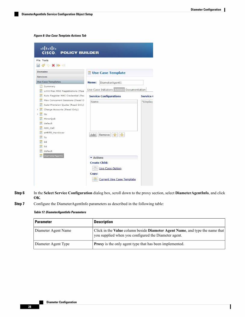
Figure 8: Use Case Template Actions Tab
Step 6 In the Select Service Configuration dialog box, scroll down to the proxy section, select DiameterAgentInfo, and clickOK.
Step 7 Configure the DiameterAgentInfo parameters as described in the following table:
Table 17: DiameterAgentInfo Parameters
DescriptionParameter
Click in the Value column beside Diameter Agent Name, and type the name thatyou supplied when you configured the Diameter agent.
Diameter Agent Name
Proxy is the only agent type that has been implemented.Diameter Agent Type
Diameter Configuration28
Diameter ConfigurationDiameterAgentInfo Service Configuration Object Setup

DescriptionParameter
Select one of the following protocols from the drop-down list:
• GX_TGPP
• GY_V8
• RX_TGPP
The other protocols in the list are not currently supported.
Proxy Protocol
In this section, you can define additional AVPs to add to the proxy request. Thefollowing parameters can be configured:
Command Code –
Request Type –
Code – Type a code for the AVP.
Value – Type a value for the AVP.
Type – Select the AVP type from the drop-down list.
Operation – Select the Operation from the drop-down list.
Vendor – Select the AVP Vendor from the drop-down list.
Proxy Request A V Ps (List)
In this section, you can define additional AVPs to add to the proxy response. Thefollowing parameters can be configured:
Command Code –
Request Type –
Code – Type a code for the AVP.
Value – Type a value for the AVP.
Type – Select the AVP type from the drop-down list.
Operation – Select the Operation from the drop-down list.
Vendor – Select the AVP Vendor from the drop-down list.
Proxy Response A V Ps (List)
Diameter ClientsThe Diameter Clients section allows for the creation of different clients identified by their realm. The clientsdefined in this section can be further used while configuring a policy so that different clients get differentservice configuration objects.
In order to define a Diameter Client you need to perform the following steps:
1. Login into Policy Builder.
2. Select Reference Data tab.
Diameter Configuration29
Diameter ConfigurationDiameter Clients

3. From the left pane, select Diameter Clients.
4. Select Summary.
5. Create the specific client that corresponds to your interface. If there is no specific client for your interfaceselect the generic Diameter Clients.
6. Provide values for at least the mandatory attributes.
Figure 9: Gx Client
The mandatory fields are marked with a “*” on the upper left corner of the field name label.Note
Once you have done that you can use the diameter client to filter the service objects that are going to be usedin a policy.
More details about each client field and attribute will be provided in the following sections dedicated to eachtype of client.
In order to filter a Service Option based on the Diameter Client you need to perform the following steps:
1. Login into Policy Builder.
2. Select Services tab
3. From the left pane, select Services.
4. Expand Service Options tree.
5. Select and expand your service option.
6. Select the service option object.
7. Select the Value cell corresponding to the Diameter Client Display Name.
8. Click the “…” button.
9. Select the Diameter Client from the popup window.
Diameter Configuration30
Diameter ConfigurationDiameter Clients

10. Click OK.
For more details about how to define a service option refer to Services.
If your service configuration object does not have a Diameter Client attribute it means it is not diameter relatedand it cannot be filtered out based on diameter client.
Note
Currently, the following diameter client types are supported:
• Diameter Clients
• Gx Clients
• Rx Clients
• Gy Clients
The diameter client feature is mainly for use with inbound realms. No validation is done as to whether a realmis unique for a specific client type. If multiple clients are defined for the same realm the behavior may beunpredictable. The interface specific diameter clients are built on top of the generic Diameter Clients. Theyadd specific behavior and this is why they should always be used in the context of the specific interface.
Note
Diameter ClientsThis generic diameter client object is supposed to be used for any interface that does not have a matchingspecific diameter client.
The following parameters can be configured under generic Diameter Client:
Table 18: Diameter Client Parameters
DescriptionParameter
The client name that is going to be used to referencethis particular client in the service configurationobject.
Name
The pattern that peer realm name should match inorder for this diameter client to be used. The patternneeds to follow the standard Java regular expressionsyntax described here.
The first choice for Realm Pattern value should alwaysbe the exact peer realm name whenever possible.
Realm Pattern
See Extract Avps, on page 42Extract Avps
Diameter Configuration31
Diameter ConfigurationDiameter Clients

DescriptionParameter
This action creates a new diameter client that is anexact copy of the current diameter client. The onlydifference between the original and the copy is that“-Copy” is appended to the name of the copy.
The Copy action works exactly the same for all typesof diameter clients.
Copy Current Diameter Client
Gx ClientsThis specific diameter client object is supposed to be used only in relation with the Gx interface. It adds Gxspecific features to the generic diameter client already described in Diameter Clients, on page 31.
Basic OptionsThe following parameters can be configured for Basic Options under Gx Client:
Table 19: Gx Client Parameters - Basic Options
DescriptionParameter
Adds Subscription-Id groupedAVP inGxCCA-imessagewith one of the followingSubscription-Id-Type AVP value and Subscription-Id-Data AVP value dependingon the selection. The values will be copied from the incoming Gx CCR-i messageif available.
• NONE (default): No Subscription-Id grouped AVP in Gx CCA
• IMSI: END_USER_IMSI (1)
• MSISDN: END_USER_E164 (0)
• NAI: END_USER_NAI (3)
Add Subscriber Id
Controls how the Flow-Direction AVP value under Flow-Information groupedAVP is derived. This option is only used for Rx dedicated bearers.
• Derive Flow-Direction: Flow-Direction AVP is derived based onFlow-Description AVP value and Flow-Status AVP value. This option isused only in case the PCEF advertised support for Rel10 feature underSupported-Features AVP. For more information refer to Table 20:Flow-Direction AVP Values, on page 34.
• 3GPP Gx Rel11 Compliant: Flow-Direction AVP is derived as per 3GPP TS29.212 v11
• Exclude Flow-Direction (default): Flow-Direction AVP is not set.
Rx PCC Rule FlowDirection Behavior
The list of APNs that are allowed to initiate IMS emergency calls as per proceduresdescribed in 3GPP TS 29.212.
Emergency CalledStation Ids
Diameter Configuration32
Diameter ConfigurationGx Clients

DescriptionParameter
Decides whether all the other sessions bound to the current Gx session getterminated upon Gx session termination.
Default value is checked.
Controls SessionLifecycle
If checked, attempts to load the session by IMSI (Subscription-Id-Data AVP valueunder Subscription-Id grouped AVP where Subscription-Id-Type AVP value isEND_USER_IMSI (1)).
Default value is unchecked.
Load By Imsi
If checked, attempts to load the session by NAI (Subscription-Id-Data AVP valueunder Subscription-Id grouped AVP where Subscription-Id-Type AVP value isEND_USER_NAI (3)).
Default value is unchecked.
Load By Nai
If checked, attempts to load the session by MSISDN (Subscription-Id-Data AVPvalue under Subscription-Id grouped AVPwhere Subscription-Id-Type AVP valueis END_USER_E164 (0)).
Default value is unchecked.
Load By Msisdn
If checked, the subscriber is identified by PCRF using “IMSI based NAI”, wherethe identity is represented in NAI form as specified in RFC 4282 [5], and formattedas defined in 3GPP TS 23.003 [6], clause 19.3.2. The IMSI based NAI is sentwithin the Subscription-Id AVP with the Subscription-Id-Type set toEND_USER_NAI at IP-CAN session establishment.
Default value is unchecked.
Imsi Based Nai
If checked, attempts to load the session by IPv4 address (Framed-IP-Address AVPvalue).
Default value is unchecked.
Load By Framed Ip
If checked, attempts to load the session by IPv6 address (Framed-IPv6-Prefix AVpvalue).
Default value is unchecked.
Load By Ip V6 Prefix
If checked, it does not attempt to terminate the Gx session by sending a Gx RARto PCEF.
Default value is unchecked.
Session Chained
If checked, removes the realm from the NAI (if present) before attempting to loadthe session by username. For more details on NAI see RFC 2486.
Default value is unchecked.
Remove Realm In UserId Mapping
Diameter Configuration33
Diameter ConfigurationBasic Options

DescriptionParameter
If checked, it does not add the Sponsor-Identity AVP to theCharging-Rule-Definition grouped AVP. This option is used only in case the PCEFadvertised support for SponsoredConnectivity feature under Supported-FeaturesAVP.
Default value is unchecked.
Exclude Sponsor IdentityAvp
If checked, attempts to load the session by IMSI and APN. In order for this optionto be effectively used 'Load By Imsi' option (described above) needs to be checked.
Default value is unchecked.
Load By Called StationId
If checked, attempts to reinstall a charging rule in case the only AVP value thatchanged for a PreConfiguredRule is the monitoring key value.
Re-install Rule onMonitoring Key Change
If checked, authorizes bound QoS between retained and calculated QoS after CPShas received QoS modification failure event from PCEF.
Default value is checked.
Limit with RequestedQoS on modificationfailure
The default value of this new attribute is TRUE (checked); that is, CPSwill performmissing Enforce Missing AVP Check validations and sendDIAMETER_MISSING_AVP (5005) result in the answer message.
However, if this attribute is FALSE (unchecked), CPS will not perform the missingAVP validation.
Enforce Missing AvpCheck
This parameter applies only to the dynamic charging rules over Gx that aregenerated by CPS due to the APPLICATION_START event trigger received overthe Sd interface for ADC rules.
If checked, CPS creates one dynamic charging rule over Gx per flow informationreceived in the Application-Detection-Info AVP over the Sd interface. CPS alsocreates a unique TDF-Application-Identifier over Gx for each of these rules. So,each generated rule has a unique TDF-Application-Identifier and only oneFlow-Information AVP.
If unchecked, CPS generates only one rule per TDF-Application-Identifier receivedover the Sd interface. This one rule has all the Flow-Information AVPs. TheTDF-Application-Identifier over Gx is same as over Sd.
Default value is unchecked.
One Gx Rule Per Flow
Table 20: Flow-Direction AVP Values
Flow-Direction AVP ValuesCriteriaPriority
UPLINK (2)Flow-Description AVP value contains “permitin”
1
DOWNLINK (1)Flow-Description AVP value contains “permitout”
2
BIDIRECTIONAL (3)FlowStatus AVP value is ENABLED (2)3
Diameter Configuration34
Diameter ConfigurationBasic Options

Flow-Direction AVP ValuesCriteriaPriority
UPLINK (2)FlowStatus AVP value is ENABLED_UPLINK(0)
4
DOWNLINK (1)FlowStatus AVP value isENABLED_DOWNLINK (1)
5
Enforce Missing AVP Check
The following is the list of AVPs for which CPS will perform the missing AVP validation if Enforce MissingAvp Check check box is selected:
• Mandatory AVPs: Origin-Host, Destination-Realm, CC-Request-Type, CC-Request-Number
• Conditional AVPs for session establishment: Subscription-Id (Subscription-Id-Type, Subscription-Id-Data),IP-CAN-Type, RAT-Type , Framed-IP-Address OR Framed-IPv6-Prefix (one must be present),AN-GW-Address (If IP-CAN-TYPE = '3GPP-EPS' or '3GPP2')
• Conditional AVPs for session modification: These AVPs are required based on the event trigger type.
• SGSN_CHANGE Event Trigger: 3GPP-SGSN-Address or 3GPP-SGSN-IPv6-Address
Applicable only to 3GPP-GPRS access types and 3GPP-EPS access types with access to the P-GWusing Gn/Gp.
• QOS_CHANGE Event Trigger: Bearer-Identifier, QoS-Information
When IP-CAN-Type is 3GPP-GPRS and if the PCRF performs bearer binding, the Bearer-IdentifierAVP shall be provided to indicate the affected bearer. QoS-Information AVP is required to beprovided in the same request with the new value.
• RAT_CHANGE Event Trigger: RAT-Type
The new RAT type must be provided in the RAT-Type AVP.
• PLMN_CHANGE Event Trigger: 3GPP-SGSN-MCC-MNC
• IP_CAN_CHANGE Event Trigger: IP-CAN-Type
The RAT-Type AVP must also be provided when applicable to the specific IP-CAN Type (forexample, 3GPP IP-CAN Type).
• RAI_CHANGE Event Trigger: RAI
Applicable only to 3GPP-GPRS and 3GPP-EPS access types.
• USER_LOCATION_CHANGE Event Trigger: 3GPP-User-Location-Info
Applicable only to 3GPP-GPRS and 3GPP-EPS access types.
• USER_LOCATION_CHANGE Event Trigger: 3GPP2-BSID
Applicable only to 3GPP2 access types.
• OUT_OF_CREDIT Event Trigger: Charging-Rule-Report, Final-Unit-Action
• REALLOCATION_OF_CREDIT Event Trigger: Charging-Rule-Report
• AN_GW_CHANGE Event Trigger: AN-GW-Address
Diameter Configuration35
Diameter ConfigurationBasic Options

• UE_TIME_ZONE_CHANGE Event Trigger: 3GPP-MS-TimeZone
• LOSS_OF_BEARER,RECOVERY_OF_BEARER,SUCCESSFUL_RESOURCE_ALLOCATION:Charging-Rule-Report
• DEFAULT _EPS_BEARER_QOS_CHANGE: Default-EPS-Bearer-QoS
• ECGI_CHANGE or TAI_CHANGE Event Trigger: 3GPP-User-Location-Info
• ACCESS_NETWORK_INFO_REPORT Event Trigger:
3GPP-User-Location-Info, if Required-Access-Info = USER_LOCATION
3GPP-MS-Timezone, if Required-Access-Info = MS_TIMEZONE
• APPLICATION_START or APPLICATION_STOP Event Trigger over Gx:TDF-Application-Identifier
Advanced Options
Cisco Pending Transaction Retry
StarOS 16 introduces optional custom behavior for handling overlapping Gx transactions so that the potentialrace conditions that can occur on Gx interface are to be handled deterministically.
This feature introduces a new error indication to allow the transaction originator to determine if a re-attemptof the transaction is appropriate. The PCRF shall send an error response to the PCEF containing theExperimental-Result-CodeAVPwith Cisco specific value DIAMETER_PENDING_TRANSACTION (4198)if the PCRF expects a response to a pending request that it initiated. The PCRF shall also have the ability toretry the request message for which it received an error response containing the Experimental-Result-CodeAVP with Cisco specific value DIAMETER_PENDING_TRANSACTION (4198).
Refer to the CISCO StarOS 16 and CISCO ASR5500 documentation for more details.
Default value (if enabled) is 1.Figure 10: Cisco Pending Transaction Retry
Max Pending Transaction Retry Count does not include the initial request. For example, in the above casethe system will send a initial message and if it fails, it will send the same message 1 more time (retry).
PCRF will cache and retry only one message per Gx session. If due to Rx IMS session interaction multipleGx RAR messages are being evaluated while another Gx RAR message is already pending than PCRF willnot reply on the Rx IMS session.
Note
Diameter Configuration36
Diameter ConfigurationAdvanced Options

Sponsored Profile
The default monitoring key name format used to track the usage when the AF provides sponsored dataconnectivity to the subscriber is:
_<Sponsor-Id>_< Rx-Session-No>
where:
• <Sponsor-Id>: Sponsor-Identity AVP value under the Sponsored-Connectivity-Data grouped AVP.
• <Rx-Session-No>: Counts how many Rx sessions have bound so far to the Gx session by the time thecurrent Rx session is created. This is an attribute of the Rx session stored on PCRF side and it doesn'tchange during the Rx session lifetime. The value starts from zero and it increases with one for each newRx session that binds.
This feature allows for customization of the monitoring key name. The monitoring key name matching theSponsor-Identity AVP value and Application-Service-Provider-Identity AVP value will be used instead ofthe default one.Figure 11: Sponsored Profile
This option is used only in case the PCEF advertised support for SponsoredConnectivity feature underSupported-Features AVP.
Rx Based QoS Upgrade of Default Bearer
This provides an option to over-ride Throttle with Boost for same priority values received inDynamic-PCC-Request-QoS.Figure 12: Rx Based QoS Upgrade
The following restrictions apply for this feature:
• This feature is applicable for QoS uplift on Default Bearer only.
• This feature overrides the earlier implementation of QoS uplift done in CPS 7.0.5 and earlier versions.
Diameter Configuration37
Diameter ConfigurationSponsored Profile

Count of Flow Description in one Charging Rule
CPS now supports the ability to split Flow Information received from the Traffic Detection Function (TDF)in a CCR-Update across multiple Charging Rules and sent over the Gx interface.
This release provides the ability for CPS to distribute the TFTs across multiple CRNs. The distribution ofTFTs keeps the Uplink and Downlink flows together in the same CRN. The number of TFTs per CRN isconfigurable. By default, CPS is configured to allow 8 TFTs per CRN.Figure 13: Count of Flow
The following parameter can be configured:
Table 21: Count of Flow Descriptions in one Charging Rule Parameters
DescriptionParameter
One TFT is equivalent to or denotes oneFlow-Description AVP received in the message.
Count of TFT’s in one Charging Rule
Max Number of Flow Descriptions on a bearer (per QCI)
Here, you can set the maximum number of flows that can be configured on the default and dedicated bearer(per QCI).
The following parameters can be configured:
These parameters apply only to the dynamic charging rules over Gx that are generated by CPS due to theAPPLICATION_START event trigger received over the Sd interface for ADC rules.
Note
Table 22: Max Number of Flow Descriptions on a bearer (per QCI) Parameters
DescriptionParameter
This parameter defines themaximum number of flowsthat can be installed on a default bearer per QCI. So,on receiving the APPLICATION_START eventtrigger over the Sd interface, CPS installs thecorresponding flows over the Gx interface and QCImaps to that of the default bearer. Essentially, this isthe limit of flows per QCI that CPS can accept fromTDF over the Sd interface. Once this limit is reached,CPS ignores any more flows received from TDF, thatis, CPS does not install any rules for those flows.
Default value is 64.
MaxNumber of FlowDescriptions on a default bearer(per QCI)
Diameter Configuration38
Diameter ConfigurationCount of Flow Description in one Charging Rule

DescriptionParameter
On receiving the APPLICATION_START eventtrigger from PCEF, CPS removes the default bearerrule and installs the dedicated bearer rule for thereceived Gx TDF-Application-Identifier. So, QCI forthe new rule maps to a dedicated bearer.
This parameter defines the the maximum number offlows per QCI that can be installed on a dedicatedbearer. Once this limit is reached, CPS ignores theAPPLICATION_START event trigger received overthe Gx interface and there is no rule or flow installedon the dedicated bearer.
Default value is 16.
Max Number of Flow Descriptions on a dedicatedbearer (per QCI)
Charging Rule Retry Configuration
Upon failure of installation of any/all of the TFTs across one or both CRNs, a configurable retry timer isactivated with a configurable number of retries for the TFTs marked as “INACTIVE”. The number of retriesand the timer interval between each retry is configurable.Figure 14: Charging Rule Retry Configuration
The following parameters can be configured under Charging Rule Retry:
Table 23: Charging Rule Retry Parameters
DescriptionParameter
The delay between retry attempts.
The default interval is 10 seconds. Also, by default,the value is capped at 15 secs (configurable). If valueis less that 15 seconds, then the retries will bescheduled at second level granularity. If value isgreater than 15 seconds, then granularity is of 1minute(overdue retry events are checked every minute ratherthan each second).
Retry Interval
Diameter Configuration39
Diameter ConfigurationCharging Rule Retry Configuration

DescriptionParameter
The maximum times retry is attempted for a rule.
Default value is 3 attempts.
Max Retry Attempts
The back-off algorithm used while determining theactual delay between retry attempts.
Currently only one option is supported:
Constant Interval: Causes the configured retry intervalto be used (without any change) for delay for all retryattempts (other options like exponential back-offwhere retry interval increases exponentially arecurrently not supported/implemented).
Backoff Algorithm
Upon failure to install TFTs even after retry, all remaining flows are removed (if there were any successfullyinstalled)followed by termination of the Sd Session. After a refresh, CPS attempts to re-establish the Sd-Session.CPS also marks the failed flows as INACTIVE.
Redirect Requests
CPS can reject incoming CCR-I messages with DIAMETER_REDIRECT_INDICATION (3006) error byacting as a redirect agent (RFC 3588). This decision to redirect a request is configured using an STG or CRD.CPS expects the STG or CRD to include a Redirect Request Column (of type True or False). There is norestriction on the condition that determines the redirect behavior.
The following parameters can be configured under Redirect Requests:
Table 24: Redirect Requests Parameters
DescriptionParameter
The result column (True/False) from the CRD usedto determine if the session needs to be redirected. Ifresult column specified here evaluates to True, sessionis redirected, else it continues as usual.
Redirect Request Column
The list of Redirect-Host AVP values to be includedin the response. If there are more than one hosts listed,all the hosts are included in the response.
Redirect Host
The Redirect-Max-Cache-Time AVP value (inseconds) to be included in the response.
Redirect Max Cache Time (in seconds)
Diameter Configuration40
Diameter ConfigurationRedirect Requests

DescriptionParameter
The Redirect-Host-Usage AVP value (in seconds) tobe included in the response. Redirect-Host-UsageAVP supports the following values:
• DONT_CACHE: The host specified in theRedirect-Host AVP should not be cached. Thisis the default value.
• ALL_SESSION: All messages within the samesession, as defined by the same value of theSession-ID AVP may be sent to the hostspecified in the Redirect-Host AVP. That is, thereis no need to consult the redirect agent for all themessages associated in the session. Identityreceived is stored until the session terminates.
• ALL_REALM: All messages destined for therealm requested may be sent to the host specifiedin the Redirect-Host AVP.
• REALM_AND_APPLICATION: All messagesfor the application requested to the realmspecified may be sent to the host specified in theRedirect-Host AVP.
• ALL_APPLICATION: All messages for theapplication requested may be sent to the hostspecified in the Redirect-Host AVP.
• ALL_HOST: All messages that would be sentto the host that generated the Redirect-Host maybe sent to the host specified in the Redirect- HostAVP.
• ALL_USER:All messages for the user requestedmay be sent to the host specified in theRedirect-Host AVP.
Redirect Host Usage
Creating an STG to Redirect Requests
You must configure an STG to determine whether an incoming CCR-I needs to be rejected or not. The stepsto configure the decision table are as follows:
The below procedure is a sample configuration based on APN and Billing plan.Note
Step 1 Log into Policy Builder.Step 2 Select the Reference Data tab.Step 3 Click Custom Reference Data Tables and select Search Table Groups.
Diameter Configuration41
Diameter ConfigurationCreating an STG to Redirect Requests

Step 4 Under Actions, click Search Table Groups.Step 5 Enter a name for the STG.Step 6 UnderResult Columns, clickAdd and enter aName,Display Name, and select the check box underUse In Condition.Step 7 Click Custom Reference Data Table under Actions > Create Child.Step 8 Enter a Name and Display Name for the CRD Table.Step 9 Under Columns, click Add and enter the following parameters as shown in the following figure:
Figure 15: Custom Reference Data Table Parameters
For apn, make sure you select Bind to Session/Policy State Field, click select and select Gx APN. Similarly, forbilling_plan, selectBind to Subscriber AVP code and enter the name or code for the AVP that represents the subscriber'sbilling plan (for example, billingplan).
Step 10 Save the PB configuration.
Extract Avps
AVPs that are required for policy decisions are extracted from the diameter message. The AVPs are specifiedby their path within the diameter message. Additionally, nested AVPs (each level delimited with ".") can alsobe extracted with or without qualifiers.
Once extracted, the AVPs are then available for use in Initiator conditions or as key AVP in CRD tables forpolicy decisions. The AVPs are not stored with the session. Thus, if some policy is enabled because of areceived message, and if there is a subsequent trigger message that does not contain that AVP, the initiatorconditions will fail and the policy is reverted.
If the AVP to be extracted appears multiple times, each of the instance will be extracted and made availableas a policy AVP. Initiator conditions can be written for one or more of these instances. Each condition willcheck all the available instances for evaluation. Thus if there are multiple instances, multiple conditions (ifconfigured) can be true for the same AVP but with different values.
The Extract Avps table lists the AVPs that must be extracted from the diameter message.
• Name: Enter a logical name for the extracted AVP. This name will be used in Initiator conditions andCRD tables to identify the extracted AVP. This is a mandatory parameter.
Diameter Configuration42
Diameter ConfigurationExtract Avps

• Avp Path: Enter the complete AVP path. This is a mandatory parameter.
• Command Code: If Command Code is specified, CPS attempts to extract the AVPs from only thatcommand (and skip the rest). This is an optional parameter.
For example:
• Name: Event-Trigger
• Avp Path: Event-Trigger
• Command Code: 272
For the above example, given a CCRwith Event-Trigger AVPs, CPS extracts each Event-Trigger AVP instanceand adds it to the current policy state.
Custom Dynamic Rule Name
For an Rx call a different Rx dedicated bearer is created for each Media-Sub-Component grouped AVP inthe incoming Rx AARmessage. This feature allows for customization of the Rx dedicated bearer name basedon the AF-Application-Identifier AVP value and Media-Type AVP value received in Rx AAR message.Figure 16: Custom Dynamic Rule Name
The default Rx dedicated bearer name format is:_<Rx-Session-No>_<MCD-No>_<Flow-Number>_<partialRulename>_<Media-Type>
where:
• <Rx-Session-No>: Counts how many Rx sessions have bound so far to the Gx session by the time thecurrent Rx session is created. This is an attribute of the Rx session stored on PCRF side and it doesn'tchange during the Rx session lifetime. The value starts from zero and it increases with one for each newRx session that binds.
• <MCD-No>: Media-Component-Number AVP value under Media-Component-Description groupedAVP for the current Media-Sub-Component grouped AVP.
• <Flow-Number>: Flow-Number AVP value for the current Media-Sub-Component grouped AVP.
• <partialRulename>: Partial Rule Name value matching the current Af Application Id and Media Typevalues for the current Media-Sub-Component grouped AVP or “AF” if no match.
• <Media-Type>: Media-Type AVP value for the current Media-Sub-Component grouped AVP.
Diameter Configuration43
Diameter ConfigurationCustom Dynamic Rule Name

Only the <partialRulename> part can be customized.Note
Rx ClientsThis specific diameter client object is supposed to be used only in relation with the Rx interface. It adds Rxspecific features to the generic diameter client already described in Diameter Clients, on page 29.
The parameters described in the following table can be configured for the Rx client:
Table 25: Rx Client Parameters
DescriptionParameters
Allows the Rx sessions initiated by this client to bind to the Gx session byother attribute than the IP address as per 3GPP TS 29.214. For moreinformation refer to Table 26: Session Binding Attribute Values, on page 46.
Session Binding Attribute
• None: When selected, CPS does not take any action on source IP.
• Replace with 'any': When selected, CPS replaces the flow descriptionsource IP with ‘any’.
• Replace with UE IP: When selected, CPS replaces flow descriptionsource IP with UE framed IP.
Flow Description Source IpEvaluation
This parameter is used to define the timer by which the STA will be heldback. Once the timer expires even if the CCR-U is not received, STA will besent to the AF and the rxSession will be removed.
Default value is 4000 milliseconds.
STA Hold Time Ms
The list of URNs that are used to indicate that a AF session relates toemergency traffic as per procedures described in 3GPP TS 29.214. For moreinformation refer to Wildcard URN. See Emergency URN List, on page 47.
Emergency URN List
When selected, CPS overrides the AF-Application-Identifier AVP value withthe Service-URN AVP value for emergency calls. This option is provided inorder to overcome the lack of AF-Application-Identifier AVP value in RxAAR in case of IMS emergency calls.
The default setting is unchecked.
Override AF App Id withURN for Emergency sessions
When selected, CPS validates the Flow-Description AVP values received aspart of Media-Sub-Component based on restrictions provided in the 3GPP29.214 Release 11 specification. If the Flow-Description value does notcomply with the format specified then the AAR request is rejected withFILTER_RESTRICTIONS (5062) value in Experimental-Result-Code.
When unchecked, CPS does not validate the Flow-Description AVP valueand simply forwards it is as is to PCEF as part of generated rules.
The default setting is unchecked.
Validate Flow-DescriptionAVP Value
Diameter Configuration44
Diameter ConfigurationRx Clients

DescriptionParameters
When selected, CPS supports the QoS handling for Preliminary Service Status.So, on receiving Service-Info-Status AVP as preliminary service informationfrom AF, CPS will generate the dynamic PCC rule and assign QCI and ARPvalues of the default bearer to these PCC rule to avoid signaling to the UE.
When unchecked, CPS ignores the Service-Info-Status AVP value and derivethe ARP andQCI values as per the QoS derivation algorithm defined in 3GPPTS 29.213 specification.
The default setting is unchecked.
29.213 standard QoS forpreliminary service
When selected, CPS automatically increments the precedence AVP value by1 for every Rx charging rule that is installed as part of any Rx session that isusing this Rx client within the same Gx session. For example, Gx session(Gx1) has one Rx session (Rx1). When Rx1 is created, two charging rulesare installed and they are assigned precedence values 1 and 2. A second Rxsession (Rx2) starts for Gx1 and also installs two Rx charging rules. Theserules are assigned precedence values 3 and 4.
The precedence values are stored in the Gx session in the rxPrecedenceCounterattribute.
Using this option overrides any other Rx charging rule precedence settings(for example, any that may have been configured for theRxSponsoredDataChargingParameters service option).
When this option is enabled, existing VoLTE deployments maybe impacted. After upgrading to CPS 11.0.0, make sure that thegateway's configuration is changed to consider precedence values.
Note
You can use the Precedence Start Value and Precedence EndValue optionsto set lower and upper limits for the precedence AVP values. If you do notset these options, the starting precedence value is set to 1 and will incrementto 9223372036854775807.
The default setting is unchecked.
Auto Increment PrecedenceAvp
When selected, CPSmanages the expiration of Rule-Deactivation time triggers.On expiration of the installed Rule-Deactivation time, CPS initiates removalof the inactive dynamic rules and tear-down of the existing Rx session.
The default setting is unchecked (false).
Remove Rule On RuleDeactivation
When selected, CPS validates the sponsor ID received in AAR request. If thereceived sponsor ID is unauthorized, CPS returnsUNAUTHORIZED_SPONSORED_DATA_CONNECTIVITY (5067) codein AAA.
The default setting is unchecked (false).
Authorize Sponsor DataConnectivity
Diameter Configuration45
Diameter ConfigurationRx Clients

DescriptionParameters
When selected, CPS enforces a unique AF-Charging-Identifier across all Rxsessions within a given subscriber or network session. During an Rx sessionestablishment, if there is already an Rx session (within the subscriber ornetwork session) containing the same AF-Charging-Identifier value, CPSrejects the new Rx session with DUPLICATED_AF_SESSION (5064)experimental result code.
The default setting is unchecked.
Enforce UniqueAF-Charging-Identifier
When selected, CPS sends time zone and location information in an Rx AAAresponse message provided that 3GPP-MS-TimeZone AVP and3GPP-User-Location-Info AVP are already received in the CCR message.
To receive the updated time zone and location information in the Rx AAAmessage, CPS should arm the UE_TIME_ZONE_CHANGE event triggerand USER_LOCATION_CHANGE event trigger in the service option underEvent-Trigger configuration.
CPS will not report this information until it is received in a CCRmessage from PCEF.
Note
Send timezone and locationinfo in AAA Response
See Extract Avps, on page 42.Extract Avps
See Netloc Access Not Supported Configuration, on page 48.Netloc Access Not SupportedConfiguration
Precedence Avp Lower And Upper
When selected, CPS automatically increments the precedence AVP value by1 for every Rx charging rule that is installed as part of any Rx session usingthis Rx Client, within the same Gx session. The precedence values are storedin the Gx session in the rxPrecedenceCounter attribute.
This value is optional, but when used, must be greater than 0 and less thanthe Precedence End Value.
Precedence Start Value
The upper limit of the precedence values for Rx charging rules that areinstalled. When this value is reached, the rxPrecedenceCounter is reset to thePrecedence Start Value.
This value is required when using the Precedence Start Value. It must begreater than the start value.
Precedence End Value
Table 26: Session Binding Attribute Values
DescriptionSession Binding Attributevalue
Attempts to bind by
• 1 Framed-IP-Address
• 2 Framed-IPv6-Prefix
IP Address (default)
Diameter Configuration46
Diameter ConfigurationRx Clients

DescriptionSession Binding Attributevalue
IMSI value and APN value from incoming requestIMSI and APN
MSISDN value and APN value from incoming requestMSISDN and APN
“IMSI and APN” and “MSISDN and APN” session binding attribute values are provided in order to supportnon 3GPP TS 29.214 compliant Rx clients.
CCR-U Wait Time (in seconds)
Emergency URN List
CPS supports wildcard service URN. For example if sos.* is configured under Emergency URN List in PolicyBuilder and when Service-URN is received from AF with “sos” “sos.fire” “sos.police” and “sos.ambulance”and so on. indicating an emergency session CPS applies special policies that are configured for Emergencysessions.
1. Select the Rx Client name created.
2. Click Add near the Emergency URN List box. A new window Add Values is displayed.Figure 17: Add Values
3. Type the name of the emergency URN that you want to add in the Value to Add (String) text box andclick Add.
4. ClickOK. In the example shown below, three URNs entries are added. To remove an URN from this listselect the URN to be removed and click Remove.
Diameter Configuration47
Diameter ConfigurationRx Clients

Figure 18: Add/Remove URN
As shown in the example above '*' has been used for wildcarding. CPS uses standard Java pattern charactersfor Emergency URNs. The pattern needs to follow the standard Java regular expression syntax described here.
Note
Netloc Access Not Supported ConfigurationCPS supports to send NetLoc-Access-Support AVP in Rx AAA or STA message based on the currentIP-CAN-Type or the values of Rat-Type AVP and AN-Trusted AVP. This is in accordance with the section4.4.6.7 of the 3GPP 29.214.
To enable this, Netloc Access Not Supported Configuration has been added under Rx Client.
Diameter Configuration48
Diameter ConfigurationNetloc Access Not Supported Configuration

Figure 19: Netloc Access Not Supported Configuration
By default, this configuration is disabled. This means that PCRF will not check for NetLoc access supportbased on IP-CAN-Type or Rat-Type AVP and AN-Trusted AVP.
If this configuration is enabled but there are no entries in the two tables associated with it, then PCRF willnot check for NetLoc access support based on IP-CAN-Type or Rat-Type AVP and AN-Trusted AVP.
The following table provides description related to the two tables under this configuration:
Table 27: Netloc Access Not Supported Configuration Tables
DescriptionTable Name
This is the list of IP-CAN-Type values for which NetLoc access is not supported. Forvalid values of the IP-CAN-Type, refer the 3GPP specification 29.212.
This table only takes integer values as input.
Default value is -1.
An entry with value = -1 must not be used for validation of NetLoc access.
List Of Ip Can Type
This is the list of Rat-Type AVP & AN-Trusted AVP values for which NetLoc accessis not supported. For valid values of the Rat-Type & AN-Trusted, refer the 3GPPspecification 29.212.
This table only takes integer values as input.
Default value is -1.
Rat Type entry with value = -1 must not be used for validation of NetLoc access.
An Trusted entry with value = -1 means that the AN-Trusted value does not care forthis entry.
List Of Rat Type
Diameter Configuration49
Diameter ConfigurationNetloc Access Not Supported Configuration
When the PCRF receives a request to report the access network information from the AF in an AAR commandor in an STR command triggered by the AF, the PCRF tries to determine whether the access network supportsthe access network information reporting based on the currently used IP-CAN type or the values of RAT-TypeAVP and AN-Trusted AVP.
PCRF first searches the list of configured IP-CAN-Type and if no match is found in the IP-CAN-Type list,then it searches the list of Rat-Type and AN-Trusted. If there is a match in any one list i.e. either the currentlyused IP-CAN-Typematches or current value of the Rat-Type andAN-Trustedmatches, then the PCRF respondsto AF with an AAA or STA command including the NetLoc-Access-Surpport AVP set to the value of 0(NETLOC_ACCESS_NOT_SUPPORTED); otherwise, it immediately configures the PCEF to provide suchaccess network information.
Gy ClientsThis specific diameter client object is supposed to be used only in relation with the Gy interface. It adds Gyspecific features to the generic diameter client already described in Diameter Clients, on page 29.
The following parameters can be configured under Gy Client:
Table 28: Gy Client Parameters
DescriptionParameters
If checked attempts to load the session by realm (Origin-Realm AVP value) andUser Id.
Default value is unchecked.
Load By Realm And UserId
If checked attempts to load the session by APN (Called-Station-Id AVP value)and User Id.
Default value is unchecked.
Load By Apn And User Id
See Extract Avps, on page 42Extract Avps
Both of the above mentioned flags help in binding the Gy session to correct Gx session when multiple Gxsessions exist for the same user.
In both cases User Id is:
AVP ValueUser Id
Subscription-Id-Data AVP value underSubscription-Id grouped AVP whereSubscription-Id-Type AVP value isEND_USER_IMSI (1)
IMSI
Subscription-Id-Data AVP value underSubscription-Id grouped AVP whereSubscription-Id-Type AVP value isEND_USER_E164 (0)
MSISDN
Diameter Configuration50
Diameter ConfigurationGy Clients

AVP ValueUser Id
Subscription-Id-Data AVP value underSubscription-Id grouped AVP whereSubscription-Id-TypeAVP value is END_USER_NAI(3)
NAI
Diameter DefaultsThe Diameter Defaults section provides global default values for different modules of the system.
In order to define a Diameter Default you need to perform the following steps:
1. Login into Policy Builder.2. Select Reference Data tab.3. From the left pane select Diameter Defaults.4. Select Summary.5. Create the specific default object according to your needs.6. Provide values for at least the mandatory fields.
• The mandatory fields are marked with a “*” on the upper left corner of the field name label.
• There should be at most one object for each diameter default type or the results will be unpredictable.The Policy Builder GUI does not enforce this restriction though.
Note
Custom AVP ProfileThis feature allows the Service Provider to extend the Diameter dictionary with new vendor specific AVPsalong with a source for that AVP and a destination where the AVP is going to be used.
The feature itself consists of two components:
• Custom Avp Table• Avp Mappings
Custom Avp TableThis table allows for the definition of the custom AVP with all the standard attributes of an AVP.
The following parameters can be configured under Custom Avp Table:
Table 29: Custom Avp Table Parameters
DescriptionParameter
Any string that is used to identify this custom AVP.AVP Name
Diameter Configuration51
Diameter ConfigurationDiameter Defaults
DescriptionParameter
AVP Code combined with Vendor Id field identifies the attribute uniquely.
• 1 - 255 Backward compatibility with Radius without setting the Vendor Id field.
• 256 - above Used for Diameter and are allocated by IANA.
Avp Code
It indicates the Vendor Id of the AVP. The following are the supported Vendor Ids:
• base (0)
• ciscoSystems (9)
• Ericsson (193)
• Tekelec (323)
• TGPP2 (5535)
• Openet (7898)
• Starent (8164)
• TGPP (10415)
• ETSI (13019)
• NSN (28458)
• Nokia (34326)
• Lucent (1751)
• Verizon (12951)
• Camiant (21274)
• Huawei (2011)
Vendor Id
Vendor Id value as assigned by IANA. The Vendor Id bit known as theVendor-Specific bit indicates whether the optional Vendor Code field is present inthe AVP header. When set the AVP Code belongs to the specific vendor code addressspace.
Vendor Code
Indicates whether support of the AVP is required. If this Bit is checked then DiameterClient Server Proxy and Translation Agent must support the handling of this AVP.
Mandatory Bit
Indicates the need for encryption for end-to-end security. If this bit is checked indicatesthat AVP data is encrypted for end-to-end security.
Protected Bit
Indicates whether the optional Vendor-ID field is present in the AVP header.Vendor Id Bit
Diameter Configuration52
Diameter ConfigurationCustom Avp Table

DescriptionParameter
Any valid basic AVP data format
• Float32Avp
• Float64Avp
• Integer32Avp
• Integer64Avp
• OctetStringAvp
• Unsigned32Avp
• Unsigned64Avp
• UTF8String
Data Type
Avp MappingsThis table allows for the mapping between the source and the destination for the custom AVP (defined in theprevious section). Multiple attributes can be used to identify both the source for the custom AVP value aswell as the destination where the AVP is going to be used.
The following mappings are supported:
• Custom AVP to Custom AVP Mapping Maps a custom AVP to another custom AVP.• 3gpp / spr AVP to 3gpp AVP Mapping Maps a 3GPP AVP or a SPR attribute to a 3GPP AVP.• 3GPP / SPR AVP to Custom AVP Mapping Maps a 3GPP AVP or a SPR attribute to a custom AVP.
Custom AVP to Custom AVP Mapping
The following parameters can be configured under Custom AVP to Custom AVP Mapping:
Table 30: Custom AVP to Custom AVP Mapping Table Parameters
DescriptionParameter
Name of AVP that has to be looked up for possiblemapping.
Source Avp
The Application Interface Id (Gx) in numeric format(16777238) on which the Source AVP is received.
Source App Id
The command code of the message on interfaceSource APPID that contains the Source AVP.
Source Cmd Code
The message indicated by Source Command Code isa request or response. Types:
• Request• Response
Source Cmd Type
This field contains the identification of the sourcepoint of the operation.
Origin Host
Diameter Configuration53
Diameter ConfigurationAvp Mappings

DescriptionParameter
This field contains the identification of the realm ofthe operation originator.
Origin Realm
AVP Name that is actually mapped to Source AVP.Target Avp
Target Application Identifier (Sy - 16777302 - for thisrelease).
Target App Id
The command code of themessage that goes on TargetAPPID and have Target AVP.
Target Cmd Code
The message having Target Command Code requestor a response.
Types:
• Request• Response
Target Cmd Type
This field contains the identification of the destinationpoint of the operation.
Destination Host
This field contains the realm of the operationdestination.
Destination Realm
Response value for Source Cmd Type and Target Cmd Type is not currently supported.
3gpp / spr AVP to 3gpp AVP Mapping
The following parameters can be configured under 3gpp / spr AVP to 3gpp AVP Mapping:
Table 31: 3gpp / spr AVP to 3gpp AVP Mapping Table Parameters
DescriptionParameter
Name of AVP that has to be looked up for possiblemapping.
Source Avp
Check if the source is an SPR attribute. The SourceAVP originates from a Source Command or fromSubscriber profile in Subscriber Profile Repository.
Default value is unchecked.
Is SPR AVP?
The Application Interface Id (Gx) in numeric format(16777238) on which the Source AVP is received.
Source App Id
The command code of the message on interfaceSource APPID that contains the Source AVP.
Source Cmd Code
Diameter Configuration54
Diameter ConfigurationAvp Mappings

DescriptionParameter
The message indicated by Source Command Code isa request or response. Types:
• None• Request• Response
Source Cmd Type
This field contains the identification of the sourcepoint of the operation.
Origin Host
This field contains the identification of the realm ofthe operation originator.
Origin Realm
AVP Name that is actually mapped to Source AVP.Target Avp
Target Application Identifier (Sy - 16777302 - for thisrelease).
Target App Id
The command code of themessage that goes on TargetAPPID and have Target AVP.
Target Cmd Code
The message having Target Command Code requestor a response.
Types:
• Request• Response
Target Cmd Type
This field contains the identification of the destinationpoint of the operation.
Destination Host
This field contains the realm of the operationdestination.
Destination Realm
Response value for Source Cmd Type and Target Cmd Type is not currently supported.
3GPP / SPR AVP to Custom AVP Mapping
The following parameters can be configured under 3GPP / SPR AVP to Custom AVP Mapping:
Table 32: 3GPP / SPR AVP to Custom AVP Mapping Table Parameters
DescriptionParameter
Name of AVP that has to be looked up for possiblemapping.
Source Avp
Check if the source is an SPR attribute. The SourceAVP originates from a Source Command or fromSubscriber profile in Subscriber Profile Repository.
Default value is unchecked.
Is SPR AVP?
Diameter Configuration55
Diameter ConfigurationAvp Mappings

DescriptionParameter
The Application Interface Id (Gx) in numeric format(16777238) on which the Source AVP is received.
Source App Id
The command code of the message on interfaceSource APPID that contains the Source AVP.
Source Cmd Code
The message indicated by Source Command Code isa request or response. Types:
• None• Request• Response
Source Cmd Type
This field contains the identification of the sourcepoint of the operation.
Origin Host
This field contains the identification of the realm ofthe operation originator.
Origin Realm
AVP Name that is actually mapped to Source AVP.Target Avp
Target Application Identifier (Sy - 16777302 - for thisrelease).
Target App Id
The command code of themessage that goes on TargetAPPID and have Target AVP.
Target Cmd Code
The message having Target Command Code requestor a response.
Types:
• Request• Response
Target Cmd Type
This field contains the identification of the destinationpoint of the operation.
Destination Host
This field contains the realm of the operationdestination.
Destination Realm
Response value for Source Cmd Type and Target Cmd Type is not currently supported.
ToD ScheduleThis feature allows for different PCC rules to be installed on a per time-of-day basis. Based on the definedschedules PCRFwill look ahead one scheduled interval every time the policy is re-evaluated and will schedulefor each PCC rule an activation time using the Rule-Activation-Time AVP and de-activation time using theRule-Deactivation-Time AVP.
Diameter Configuration56
Diameter ConfigurationToD Schedule

Figure 20: ToD Schedule
• Both Start Time and End Time need to be defined in hhmm 24hr format.• UE time zone (3GPP-MS-TimeZone AVP) if available takes precedence over PCRF time-zone.• ToD schedule should be complete for 24 hours.• There should be no overlapping between the different schedule Switch Times.• First charging schedule should start at mid-night with start-time value as 0000 and last schedule shouldend on next mid-night with end-time value as 2359. Time entry with 2359 is rounded up to the nextminute to complete the 24 hour schedule.
The ToD Schedule can be referenced only from a PreDefinedRule, PreDefinedRuleBase or aPreConfiguredRule service configuration object.
In order to use a ToD Schedule in a Service Option you need to perform the following steps
1. Login into Policy Builder.2. Select Services tab.3. From the left pane select Services.4. Expand Service Options tree.5. Select and expand your service option.6. Select the service option object.7. Select the Value cell corresponding to the ToD Schedule.8. Push the “…” button.9. Select the ToD Schedule from the popup window.10. Click OK.
Diameter Configuration57
Diameter ConfigurationToD Schedule

Figure 21: ToD Schedule - Service Option
For more details about how to define a service option refer to Services.
Sd Push RulesThis section supports the Sd solicited reporting scenario when the TDF-Information grouped AVP is not sentfrom the PCEF to the PCRF in a Gx CCR-i. For more information on Sd solicited reporting refer to 3GPP TS29.212.Figure 22: Sd Push Rules
The following parameters can be configured under Sd Push Rules:
Diameter Configuration58
Diameter ConfigurationSd Push Rules

AVPAttributeMessageParameter Type
Origin-RealmGx RealmGx CCR-iInput
Origin-HostGx Host Pattern
Destination-RealmTDF RealmSd TSROutput
Destination-HostTDF Host
• The first choice for Gx Host Pattern value should always be the exact peer realm namewhenever possible.• No Sd session is initiated if there's no match for the input columns in the Sd Push Rules table.
Note
Gx ProfileThis section provides default values to be used for Gx default bearer QoS parameters as well as some specificbehavior related to default bearer QoS.
The following parameters can be configured under Gx Profile:
Table 33: Gx Profile Parameters
DescriptionParameter
Controls whether the configured default bearer QoS will be installedon the default bearer or on the secondary bearers.
• PushOnDefaultBearerQoS (default)• PushWithUpgradedDefaultBearerQoS
Push Pre Configured Rule Options
Allows for a default APN name to be defined. This APN name is goingto be further used as an input into the AF Application Id Validationfeature described below. The APN value will be set based on theavailable data and the priorities described below.
• 1 - A policy derived AVP having the same value as the LogicalApn
• 2 - Called-Station-Id AVP from incoming Rx AAR• 3 - Called-Station-Id AVP from Gx session
Logical Apn
Gx client names that are allowed not to have a default bearer QoSinstalled. In case a default bearer QoS has not been configured in thepolicy and the Gx client name has not been added to this list an errorresponse will be sent to the PCEF containing the Result-Code AVPvalueDIAMETER_ERROR_BEARER_NOT_AUTHORIZED(5143).
Gx Client QoS Exclusion List
Controls whether the requested QoS should be granted or not as thedefault bearer QoS.
Default value is unchecked.
Grant Requested QoS
Diameter Configuration59
Diameter ConfigurationGx Profile

DescriptionParameter
If this option is selected then the requested QoS should be granted evenif the global QoS is provisioned. There are three type of QoS first istaken from service second is from default QoS and third one is fromrequest. If this flag is checked then requested QoS will take priorityover default QoS.
Default value is unchecked.
Grant Requested Qos Over GlobalQos
Global Default Granted QoS
The QoS class identifier identifies a set of IP-CAN specific QoSparameters that define QoS excluding the applicable bitrates and ARP.It is applicable both for uplink and downlink direction. The QCI values0 10 – 255 are divided for usage as follows
• 0 - Reserved• 10-127 - Reserved• 128-254 - Operator specific• 255 - Reserved
Qci
It defines the maximum bit rate allowed for the uplink direction.Max Req Bandwidth UL
It defines the maximum bit rate allowed for the downlink direction.Max Req Bandwidth DL
It defines the guaranteed bit rate allowed for the uplink direction.Guaranteed Bit Rate UL
It defines the guaranteed bit rate allowed for the downlink direction.Guaranteed Bit Rate DL
It defines the total bandwidth usage for the uplink direction of non-GBRQCIs at the APN.
Apn Agg Max Bit Rate UL
It defines the total bandwidth usage for the downlink direction ofnon-GBR QCIs at the APN.
Apn Agg Max Bit Rate DL
When selected, pending policy calculation is enabled for one look aheadin advance.
Enable Pending Policy Evaluation
ARPSelect the Arp type from the drop-down list to open parameters for the corresponding selection. ARP is usedto indicate the priority of allocation and retention.
The following parameters can be configured under Arp:
Diameter Configuration60
Diameter ConfigurationARP

Table 34: ARP Parameters
DescriptionParametersSelection
The priority level is used to decide whether a bearer establishment ormodification request can be accepted or needs to be rejected in case ofresource limitations (typically used for admission control of GBR traffic).The AVP can also be used to decide which existing bearers to pre-emptduring resource limitations. The priority level defines the relativeimportance of a resource request. Values 1 to 15 are defined with value1 as the highest level of priority.
• Values 1 to 8 - assigned for services that are authorized to receiveprioritized treatment within an operator domain.
• Values 9 to 15 - Can be assigned to resources that are authorizedby the home network and thus applicable when a UE is roaming.
Priority LevelAllocationRetentionPriority
If it is provided within the QoS-Information AVP the AVP defineswhether a service data flow can get resources that were already assignedto another service data flow with a lower priority level. If it is providedwithin the Default-EPS-Bearer-QoS AVP the AVP defines whether thedefault bearer can get resources that were already assigned to anotherbearer with a lower priority level.
• 0 This value indicates that the service data flow or bearer is allowedto get resources that were already assigned to another service dataflow or bearer with a lower priority level.
• 1 This value indicates that the service data flow or bearer is notallowed to get resources that were already assigned to anotherservice data flow or bearer with a lower priority level. This is thedefault value applicable if this AVP is not supplied.
PreemptionCapability
If it is provided within the QoS-Information AVP the AVP defineswhether a service data flow can lose the resources assigned to it in orderto admit a service data flow with higher priority level. If it is providedwithin the Default-EPS-Bearer-QoS AVP the AVP defines whether thedefault bearer can lose the resources assigned to it in order to admit apre-emption capable bearer with a higher priority level.
• 0 This value indicates that the resources assigned to the service dataflow or bearer can be pre-empted and allocated to a service dataflow or bearer with a higher priority level. This is the default valueapplicable if this AVP is not supplied.
• 1 This value indicates that the resources assigned to the service dataflow or bearer shall not be pre-empted and allocated to a servicedata flow or bearer with a higher priority level.
PreemptionVulnerability
Diameter Configuration61
Diameter ConfigurationARP

DescriptionParametersSelection
It contains information that identifies the particular service that the AFservice session belongs to. This information may be used by the PCRFto differentiate QoS for different application services.
You can specify regular expressions for this parameter as needed.
AF ApplicationIdentifier Pattern
ApplicationQoS Policy
Applicable Media-Type (session level or specific toMedia-Component-Description). The list includes Audio Video DataApplication Control Text Message and Other.
Media Type
The Reservation Priority includes the priority value of the related priorityservice. The Reservation Priority is populated with a default value if thepriority value is unknown.
ReservationPriority
ReservationPriority QoSPolicy
The QoS class identifier identifies a set of IP-CAN specific QoSparameters that define QoS excluding the applicable bit rates and ARP.It is applicable both for uplink and downlink direction. The QCI values0 10 – 255 are divided for usage as follows:
• 0 Reserved• 10-127 Reserved• 128-254 Operator specific• 255 Reserved
QciBase MPSQoS/BaseMPSQoS Gx
TheMPS Id contains the national variant forMPS service name indicatingan MPS session.
MPS IdMPS QoS
Applicable Media-Type (session level or specific toMedia-Component-Description). Select from drop-down list. The listincludes Audio Video Data Application Control TextMessage and Other.
Media Type
Relaxed USAGE_REPORT Event-Trigger HandlingUse this checkbox to enable the functionality for supporting old event-trigger value (26) for the usage report.This configuration will be applicable only when CPS is configured to use R10 event-trigger values byunchecking the 'Use V9 Event Trigger Mapping' flag in Diameter Configuration.
Peers using Event-Trigger value (26) for USAGE_REPORT
The following table contains the list of realm and host entries for which CPS will support old event-triggervalue (26) for USAGE_REPORT.
The parameters can be configured under Relaxed USAGE_REPORT Event-Trigger Handling:
Table 35: Relaxed USAGE_REPORT Event-Trigger Handling Parameters
DescriptionParameter
The pattern that peer realm name should match in order for this diameter client tobe used.
The pattern needs to follow the standard Java regular expression syntax describedhere.
Realm Pattern
Diameter Configuration62
Diameter ConfigurationRelaxed USAGE_REPORT Event-Trigger Handling

DescriptionParameter
Host name pattern as received in Origin-Host AVP in AAR message. The patternneeds to follow standard Java pattern conventions. The pattern needs to follow thestandard Java regular expression syntax described here.
Host Pattern
QoS Retry on APN-AMBR_FAILURE_MODIFICATIONUse this check box to receive APN-AMBR_FAILURE_MODIFICATION events from PCEF.
The following parameters can be configured underQoS retry onAPN-AMBR_FAILURE_MODIFICATION:
Table 36: QoS retry on APN-AMBR_FAILURE_MODIFICATION Parameters
DescriptionParameter
Number of retries to push calculated QoS information.Number Of Retry
In the caseGGSN sendsAPN-AMBR_FAILURE_MODIFICATION reportto CPS, following are the retry options in which CPS sends the QoSinformation:
• Immediate Retry: CPS calculates QoS based on the configured policyand sends it immediately in a CCA message.
• Delayed Retry: CPS responds to CCA-Uwithout any QoS informationunless there is difference between the current derived QoS andpreviously sent QoS. CPS sends the QoS information in the next RARor CCA-U message.
QoS Retry Options
CPS retries sending the QoS information "n” times, to avoid looping. Afterexhaustion of the retries, following are the options:
• Continue Session: CPS does not send same QoS information insubsequent CCA-U message unless there is a difference between thecurrent calculated QoS and previously sent QoS.
• Terminate Session: CPS sends RAR with Release Cause value asUNSPECIFIED_REASON after the time configured in Time ToTrigger Release RAR expires. On receiving CCR-T, CPS terminatesthe session.
Action On QoS Retry Exhaust
CPS sends RAR with Release Cause value as UNSPECIFIED_REASONafter the time configured in Time To Trigger Release RAR expires.
Time To Trigger Release RARIn Minutes
Once CPS receives APN-AMBR_FAILURE_MODIFICATION, CPS setsnext reset timer to value configured in Time to Reset QoS Retry Counter.If CPS does not receive APN-AMBR_FAILURE_MODIFICATIONwithinthis specified time, CPS resets the retry count to 0.
Time To Reset QoS RetryCounter In Minutes
Diameter Configuration63
Diameter ConfigurationQoS Retry on APN-AMBR_FAILURE_MODIFICATION

MPS ProfileThis section provides default values to be used if MPS feature is needed to support eMPS priority. The MPSProfile providesMPS attributes required for priority service provisioning. The priority level value from Serviceconfiguration takes precedence over MPS Profile value.
There must be at least one Mps Profile defined underMps Profiles.Note
Figure 23: MPS Profile
The following parameters can be configured underMps Profile:
Table 37: MPS Profile Parameters
DescriptionParameter
List of IMS APNs for which the MPS feature issupported.
This field can accommodate several Ims Apn that areused to match with the incoming service request forpriority service. The values that are received by theDefault Bearer QoS are looked up for a suitable ImsApn match. If the APN value of a Gx session requestmatches IMSAPN IMS signaling priority fromEMPSservice is used as priority level.
Ims Apn
Diameter Configuration64
Diameter ConfigurationMPS Profile

DescriptionParameter
For information on parameters under Mps QoS referto ARP Parameters.
Mps QoS
For additional information on 3GPP specifications refer to http//www.3gpp.org/DynaReport/29212.htm.
The above link is compliant with Release 11.
Rx ProfileThis section provides default and specific values to be used by the different QoS parameter mapping functionsat PCRF as per 3GPP TS 29.213. This section also provides a mechanism to authorize the Rx IMS sessions.
Basic OptionsDefault QoS Policy
Provides the values to be used during the derivation of the Maximum Authorized Data Rates AuthorizedGuaranteed Data Rates MaximumAuthorized QoS Class per IP flow or bidirectional combination of IP flowsin the PCRF and for calculating the MaximumAuthorized/Guaranteed Data Rates QCI and ARP in the PCRFwhenever the “as set by the operator” phrase is used in the algorithm description.
For description of different parameters under Default QoS Policy refer to Table 33: Gx Profile Parameters,on page 59.
MPS QoS Policy
Provides a way to derive QoS attributes for MPS sessions based on some other AVP values.
For description of different parameters under MPS QoS Policy refer to Table 34: ARP Parameters, on page61.
A Media-Type having an empty label shall be used only to get the output values to be used for default bearerQoS.
Note
Application QoS Policy
Provides a way to derive Rx dedicated bearers QoS attributes based on AF-Application-Identifier AVP valueas per 3GPP TS 29.213.
For description of different parameters under Application QoS Policy refer to Table 33: Gx Profile Parameters,on page 59 and Table 34: ARP Parameters, on page 61.
Codec QoS Policy
Provide a way to derive Rx dedicated bearers QoS attributes based on Codec-Data AVP value as per 3GPPTS 29.213.
For description of different parameters under Codec QoS Policy refer to Table 33: Gx Profile Parameters, onpage 59 and Table 34: ARP Parameters, on page 61.
The additional parameters Codec Data Pattern and Codec Details Pattern contains codec related informationknown at the AF. This information is encoded as per 3GPP 29.214 specifications
Diameter Configuration65
Diameter ConfigurationRx Profile

The first line of the value of the Codec-Data AVP consists of either the word uplink or the word downlink
(in ASCII) followed by a new-line character. The semantics of these words are the following:
• uplink indicates that the SDP was received from the UE and sent to the network.
• downlink indicates that the SDP was received from the network and sent to the UE.
Restrictions
• You should not configure 'Codec QoS Policy' table with ambiguous entry. If multiple rows are configuredwhich matches same 'Codec-Data' and 'Codec-Details' values then CPS will fetch first matched row.
• Codec-Data column value is mandatory in Policy Builder configuration while adding entry in the 'CodecQoS Policy' table.
• CPS considers the first Codec-Data AVP if AAR request has multiple 'Codec-Data' AVPs.
• You should configure the 'Codec Data Pattern' and 'Codec Details Pattern' column values with wildcardsas per the standard Java regular expression syntax described at the link.
CPS supports leading middle and trailing wildcards. Multiple wildcards shouldbe possible in a single string. The following sections provides few examples onhow to configure the wildcards).
Important
• Case sensitivity is supported for both 'Codec Data Pattern' and 'Codec Details Pattern' columns so youshould provide the values accordingly.
If multiple Codec-Data AVPs are reported in multiple AAR messages for a single Rx session then CPS willconsider the first Codec-Data AVP value received in first AAR message for selecting QoS policies.
For example:
1. Codec Data value used as the search key in this table is the 4th group (of numbers) from the 3rd line ofthe Codec-Data AVP string value.
In the example below only the value 116 is going to be used as a search key in the Codec QoS Policytable.uplinkofferm=audio 50000 RTP/AVP 116 107 97 115 111 110a=rtpmap116 AMR-WB/16000a=rtpmap107 AMR-WB/16000a=rtpmap97 AMR/8000a=rtpmap115 AMR/8000a=rtpmap111 telephone-event/16000a=rtpmap110 telephone-event/8000a=currqos local nonea=currqos remote nonea=desqos mandatory local sendrecva=desqos optional remote sendrecva=sendrecva=ptime20a=maxptime240
2. Only the first Codec-Data AVP value is used.
Diameter Configuration66
Diameter ConfigurationBasic Options

3. You can configure Codec Details Pattern and Codec Data Pattern columns with wildcards as per javaregular expressions (for example, .* $, and so on) so that CPS can compare the AVP values with thisregex and fetch the appropriate QoS values.
Example:
Consider you want to configure “Codec Data Pattern 98" and “Codec Details Pattern AMR/8000”.
There are multiple combination you can configure. Some examples are given below :
With ExactMatch:
• Codec Data Pattern 98 Codec Details Pattern AMR/8000.• Codec Data Pattern 98 Codec Details Pattern <No value specified>, that is, null
With wildcards
• Codec Data Pattern .*8 Codec Details Pattern AM.*• Codec Data Pattern 9.* Codec Details Pattern .*80• Codec Data Pattern 9.* Codec Details Pattern AM.*80• Codec Data Pattern .* Codec Details Pattern ^AM.*80
AM.*80 indicates that String that has AM and any number characters and 80. It does not mean that stringshould start with AM and end with 80.
If you want to specify starting and ending characters explicitly then you should use '^' for starting (say^77 value should start with 77) and '$' for ending (say AM.*80$ value should end with 80); you shouldconfigure the 'Codec Data Pattern' and 'Codec Details Pattern' column as per the standard Java regularexpression syntax.
Suppose you configure multiple rows matching the same values; for example, as shown in the followingfigure, both rows can be matched with values “Codec-Data 98 and Codec-Details AMR/8000." In thiscase, CPS will select the first matched row.Figure 24: Codec QoS Policy
Reservation Priority QoS Policy
Provides a way to derive Rx dedicated bearers QoS attributes based on Reservation-Priority AVP value asper 3GPP TS 29.213.
For description of different parameters under Reservation Priority QoS Policy refer to Table 33: Gx ProfileParameters, on page 59 and Table 34: ARP Parameters, on page 61.
Af Application Id Validation
Provides a way to authorize the Rx IMS sessions. In case there's not a match between the AVP values belowin the table the PCRF shall send an error response to the AF containing the Experimental-Result-Code AVPwith value REQUESTED_SERVICE_NOT_AUTHORIZED (5063) as per 3GPP TS 29.214.
Diameter Configuration67
Diameter ConfigurationBasic Options

AVP ValueInterface
Refer to Logical APN attribute under Gx Profile, onpage 59.
Gx
AF-Application-IdentifierRx
Media-Type
• Called-Station-Id AVP value is retrieved from the Gx session the Rx session binds to.• If the incoming Rx AAR message contains multiple flows having different AF-Application-IdentifierAVP value or Media-Type AVP value and any of these flows is not authorized than the PCRF shall sendan error response as described above.
• If no AF-Application-Identifier AVP is present in the incoming request the validation is skipped.
Note
Advanced OptionsYou can get access to these features by creating child objects to your Rx profile object.
There should be at least one object of each type for any Rx profile object or the results will be unpredictable.The Policy Builder GUI does not enforce this restriction though.
Note
Sponsored Data Charging Parameters
The Sponsored Data Charging Parameters allows you to configure specific charging parameters for theSponsored Data scenarios depending on some AVPs from the incoming Rx AAR. These parameters are goingto be set under Charging-Rule-Definition grouped AVP.
The required charging parameters are as follows:
• Rating-Group• Reporting-Level• Online• Offline• Metering-Method
To map the above mentioned parameters the following keys are used:
• Sponsor-Id• Application-Service-Provider-Identity• Media Type
These keys are applicable for Sponsored Data Charging Parameters only.
Themapping configuration for the charging parameters is configured underPolicy Builder >Reference Datatab > Diameter Defaults > Rx Profile.
Diameter Configuration68
Diameter ConfigurationAdvanced Options

Figure 25: Sponsor Data Charging
In the Sponsor Data Charging table, you can define the parameter values in all the columns including thevalues for the key parameters such as - Sponsor Identity App Service Provider Identity and Media Type.
Default Sponsor Data Charging
Defines the default values for the sponsor data charging parameters under Charging-Rule-Definition groupedAVP to be used in case there's no match in the Sponsor Data Charging. This configuration is optional. Defaultvalue is unchecked.
The following parameters can be configured under Sponsor Data Charging:
Table 38: Sponsor Data Charging Parameters
DescriptionParameter
The identity of the service or service component the service data flow in aPCC rule relates to.
Service Identifier
The charging key for the PCC rule used for rating purposes.Rating Group
It defines whether the online charging interface from the PCEF for theassociated PCC rule is enabled. The default charging method provided by theCPS takes precedence over any pre-configured default charging method at thePCEF.
• Enable This value is used to indicate that the online charging interfacefor the associated PCC rule is enabled.
• Disable This value is used to indicate that the online charging interfacefor the associated PCC rule is disabled.
Online
It defines whether the offline charging interface from the PCEF for theassociated PCC rule is enabled.The default charging method provided by theCPS takes precedence over any pre-configured default charging method at thePCEF.
• Enable This value is used to indicate that the offline charging interfacefor the associated PCC rule is enabled.
• Disable This value is used to indicate that the offline charging interfacefor the associated PCC rule is disabled.
Offline
Diameter Configuration69
Diameter ConfigurationAdvanced Options

DescriptionParameter
The Metering-Method AVP (AVP code 1007) is of type Enumerated and itdefines what parameters shall be metered for offline charging. The PCEFmayuse the AVP for online charging in case of decentralized unit determinationand having three values
• DURATION (0) This value shall be used to indicate that the duration ofthe service data flow shall be metered.
• VOLUME (1) This value shall be used to indicate that volume of theservice data flow traffic shall be metered.
• DURATION_VOLUME (2) This value shall be used to indicate that theduration and the volume of the service data flow traffic shall be metered.
Metering Method
The Reporting-Level AVP is of type Enumerated and it defines on what levelthe PCEF reports the usage for the related PCC rule.There are three types ofreporting levels
• SERVICE_IDENTIFIER_LEVEL (0) This value shall be used to indicatethat the usage shall be reported on service id and rating group combinationlevel and is applicable when the Service-Identifier and Rating-Grouphave been provisioned within the Charging-Rule-Definition AVP andRating-Group AVP have been provisioned within theCharging-Rule-Definition AVP. Applicable for offline charging.
• RATING_GROUP_LEVEL (1) This value shall be used to indicate thatthe usage shall be reported on rating group level and is applicable whenthe Rating-Group has been provisioned within theCharging-Rule-Definition AVP and Rating-Group AVP have beenprovisioned within the Charging-Rule-Definition AVP. Applicable foroffline charging.
• SPONSORED_CONNECTIVITY_LEVEL (2) This value shall be usedto indicate that the usage shall be reported on sponsor identity and ratinggroup combination level and is applicable when the Sponsor-IdentityAVPApplication-Service-Provider-Identity AVP and Rating-Group AVP havebeen provisioned within the Charging-Rule-Definition AVP. Applicablefor offline charging.
Reporting Level
This determines the order in which the service data flow templates are appliedat service data flow detection at the PCEF. A PCC rule with the PrecedenceAVP with lower value shall be applied before a PCC rule with the PrecedenceAVP with higher value.
Precedence
Sponsor-Identity AVP value under the Sponsored-Connectivity-Data groupedAVP.
Sponsor Identity
App Service Provider Id is same as Sponsor-Identity. It is an AVP under theSponsored-Connectivity-Data grouped AVP.
App Service Provider
Applicable Media-Type (session level or specific toMedia-Component-Description). Select from drop-down list. The list includesAudio Video Data Application Control Text Message and Other.
Media Type
Diameter Configuration70
Diameter ConfigurationAdvanced Options

Dynamic Rule Charging Parameter
The Dynamic Rule Charging Parameters allows you to configure different charging parameters for the Rxdedicated bearers. Charging parameters are defined for dynamic PCC rules so that the service provider canproperly charge for the traffic. For each Media-Sub-Component grouped AVP underMedia-Component-Description grouped AVP in an AAR request PCRF installs a dynamic charging rule. Thecharging parameters for these dynamic PCC rules are not included in the AAR message so they are pulledout from the configuration.Figure 26: Charging Parameters
In the Charging Parameters table, you can define the parameter values in all the columns including thevalues for the key parameters such as - AF Application Identifier Pattern andMedia Type.
The AF Application Identifier Pattern parameter contains information that identifies the particular servicethat the AF service session belongs to. This information may be used by the PCRF to differentiate QoS fordifferent application services. You can specify regular expressions for this parameter as needed.
Default Charging Parameters
Defines the default values for the charging parameters under Charging-Rule-Definition grouped AVP to beused in case there's no match in the Charging Parameters table. This configuration is optional. Default valueis unchecked.
For description of different parameters under Dynamic Rule Charging Parameters refer to Table 38: SponsorData Charging Parameters, on page 69.
• An empty value being selected in either of Online Offline or Metering Method drop-boxes means novalue is defined for that attribute so it will not be added to the Charging-Rule-Definition grouped AVP.Default value for all these three attributes is empty.
• The same parameters can be configured using an RxChargingParameterSTGConfiguration serviceconfiguration object.
Note
Rule Retry ProfilesCPS can be configured to selectively re-attempt to install rules that fail to install or activate. Upon receipt ofa Charging-Rule-Report indicating the failure to install or activate one or more rules CPS will evaluate thefailed rules and take further action.
CPS decides whether to reinstall a failed rule based on the Rule Retry Profile configured for the rule. Theconfiguration of this Rule Retry behavior takes place in the Rule Retry Profile screen in Policy Builder.
Diameter Configuration71
Diameter ConfigurationRule Retry Profiles

• CPS will not re-attempt to install a failed rule unless the rule has a Rule Retry Profile associated with it.If no Rule Retry Profile is configured the rule status and failure code are updated immediately and noattempt to install the rules is made. This is the default behavior.
• If the Rule Retry Profile is configured but the reported rule failure code does not match any of the failurecodes defined in the associated Rule Retry Profile the rule status and failure code are updated immediatelyand no attempt to install the rules is made regardless of the status of the other parameters.
• The rule status is not updated until the last retry fails.
Create a Rule Retry Profile
Step 1 Login to Policy Builder.Step 2 Go to Reference Data > Rule Retry Profiles.Step 3 From the right pane, click Rule Retry Profile under Create Child to open a Rule Retry Profile.
The following parameters can be configured for each Rule Retry Profile:
Table 39: Rule Retry Profile Parameters
DescriptionParameter
The number of seconds to wait before retrying to install a rule. See also BackoffAlgorithm parameter.
Default: 10 seconds
Retry Interval
The maximum number of retry attempts to make. When CPS reaches thismaximum retry value without successfully installing the rule the rule statusand failure code are updated immediately and no further attempts are made toinstall the rule.
Note This value does not include the initial installation attempt that is reportedas failed but only the subsequent attempts.
Default: 3
Max Retry Attempts
The algorithm to be used for calculating the time between retries.
CONSTANT_INTERVAL Each retry is scheduled after an interval equal toRetry Interval seconds since the last report.
LINEAR_INTERVAL Each retry is scheduled after an interval equal to RetryInterval x Current Attempt Number seconds since the last report.
Default: CONSTANT_INTERVAL
Backoff Algorithm
Select the failure codes for which CPS retries as specified in 3GPP TS29.212v11.10 Section 5.3.38 Rule-Failure-Code AVP.
Click Add then select one or more failure codes from the drop down menu.Click Add to include them to the list. Click OK when you are done.
If no Rule Failure Code is specified, then CPS retries regardless of the failurecode reported.
Rule Failure Code
Diameter Configuration72
Diameter ConfigurationCreate a Rule Retry Profile

DescriptionParameter
Enter a unique name for this Rule Retry Profile.
This name is used to associate Rules to this Rule Retry Profile.
Name
Enter the maximum time in seconds between the first and the last retry.
If set to zero, the PCRF does not enforce a time limit for sending the retrymessages.
Default: 0 (zero)
Max Retry Interval
If there is still time to retry a rule installation (First Retry Time + Max Retry Interval <= Current Time) then the rulestatus and failure code are not updated immediately such that no policy change based on rule failure status is triggered.
Associate a Rule Retry Profile with a RuleEach type of Service Configuration Object Rule in CPS (PreDefinedRule PreDefinedRuleBasePreConfiguredRule) can be associated with the Rule Retry Profile created in the previous section.
Step 1 In Policy Builder select the Services tab.Step 2 From the left pane select Services.Step 3 Expand Service Options tree.Step 4 Select and expand your service option.Step 5 Select the service option object.Step 6 In the Service Option screen select the Service Configuration object. A Rule Retry Profile can be referenced only from
a PreDefinedRule, PreDefinedRuleBase or a PreConfiguredRule service configuration object.Step 7 Select the Value cell corresponding to the Retry Profile.Step 8 Click the “…” button.Step 9 Select the Rule Retry Profile from the popup window then click OK.Step 10 Click OK.
For more details about how to define a service option refer to Services chapter.
Diameter Configuration73
Diameter ConfigurationAssociate a Rule Retry Profile with a Rule

Diameter Configuration74
Diameter ConfigurationAssociate a Rule Retry Profile with a Rule