Embed Size (px)
Citation preview

Diagnostics Commands
This module provides command line interface (CLI) commands for configuring diagnostics on your router.
To use commands of this module, you must be in a user group associated with a task group that includesappropriate task IDs. If the user group assignment is preventing you from using any command, contact yourAAA administrator for assistance.
• diagnostic load, page 2
• diagnostic monitor, page 4
• diagnostic monitor interval, page 6
• diagnostic monitor syslog, page 8
• diagnostic monitor threshold, page 9
• diagnostic ondemand action-on-failure, page 11
• diagnostic ondemand iterations, page 13
• diagnostic schedule, page 14
• diagnostic start, page 17
• diagnostic stop, page 19
• diagnostic test-parameters, page 21
• diagnostic unload, page 23
• ping (administration EXEC), page 25
• show diag , page 30
• show diagnostic bootup level, page 35
• show diagnostic content, page 36
• show diagnostic ondemand settings, page 40
• show diagnostic result, page 41
• show diagnostic schedule, page 47
• show diagnostic status, page 49
• show run diagnostic monitor, page 51
Cisco IOS XR Interface and Hardware Component Command Reference for the Cisco CRS Router, Release 4.2.x
OL-26065-03 1

diagnostic loadTo load an offline diagnostic image for integrated field diagnostics, use the diagnostic load command inAdmin EXEC mode.
diagnostic load location node-id [autostart {all| basic}]
Syntax Description Loads an offline diagnostic image for a specified location. The node-id argumentis entered in the rack/slot/module notation. All modules in the specified slot areloaded with the offline diagnostic image.
location node-id
(Optional) Starts running the diagnostic tests after the image has loaded. Thefollowing options are available:
• all—Runs all tests.
• basic—Runs basic tests
autostart {all | basic}
Command Default None
Command Modes Admin EXEC mode
Command History ModificationRelease
This command was introduced.Release 3.4.0
Usage Guidelines Use the diagnostic load command to load an offline diagnostic image used for integrated field diagnostics.Loading a diagnostic image places the specified card out of service.
The time it takes to load a diagnostic image varies depending on the card. Use the show platform commandto determine if the image has been loaded and if the card has been placed out of service.
The distributed route processor (DRP) does not support the automatic running of tests when the image isloaded for CPU0 and CPU1. After the diagnostic image is loaded, use the diagnostic start location node-idtest {id | all | basic | non-disruptive} command to execute the tests.
Note
For more information about running Cisco IOS XR diagnostics, refer to Cisco IOS XR Diagnostics.
Cisco IOS XR Interface and Hardware Component Command Reference for the Cisco CRS Router, Release4.2.x
2 OL-26065-03
Diagnostics Commandsdiagnostic load
Task ID OperationsTask ID
executediag
Examples The following example shows how to load an offline diagnostic image:
RP/0/RP0/CPU0:router# admin
RP/0/RP0/CPU0:router(admin)# diagnostic load location 0/0/CPU0 autostart basic
diagnostic load will bring requested slot out of service. [confirm(y/n)] yUser has confirmed diagnostic load requestPreparing UUT for Diagnostics software.Downloading IDS diagnostics image /pkg/ucode/hfr-diag-l3sp-fdiagsDownloading IDS diagnostics image /pkg/ucode/hfr-diag-l3-fdiagsPlease wait for UUT image downloading ...diagnostic load in progress.
Related Commands DescriptionCommand
Displays information and status of each node in thesystem.
show platform
Cisco IOS XR Interface and Hardware Component Command Reference for the Cisco CRS Router, Release 4.2.x
OL-26065-03 3
Diagnostics Commandsdiagnostic load
diagnostic monitorTo configure the health-monitoring diagnostic testing for a specified location, use the diagnostic monitorcommand in administration configuration mode. To remove the specified command from the configurationfile and restore the system to its default condition, use the no form of this command.
diagnostic monitor location node-id test {id| test-name} [disable]
no diagnostic monitor location node-id test {id| test-name} [disable]
Syntax Description Location to enable diagnostic monitoring. The node-id argument is entered in therack/slot/module notation.
node-id
Specifies diagnostic test selection. The following test selections are available:
• id—Test ID .
• test-name—Name of the test.
Use the show diagnostic content command in administration EXEC mode to seea list of test names and their associated IDs.
test {id | test-name}
Disables diagnostic monitoring for a specified location.disable
Command Default To view the default value for each test, use the show diagnostic content command in administration EXECmode when the diagnostic image is first installed. The default may be different for each test.
Command Modes Administration configuration
Command History ModificationRelease
This command was introduced.Release 3.4.0
Usage Guidelines Use the diagnostic monitor command to enable or disable health-monitoring diagnostic testing for a specifiedtest at the specified location.
Use the disable keyword to disable a health-monitoring diagnostic test that is enabled by default. For example,if test 1 is enabled by default, the disable keyword disables the diagnostic test. If the no form of the commandis used, the test is set to the default condition, which is enabled.
Cisco IOS XR Interface and Hardware Component Command Reference for the Cisco CRS Router, Release4.2.x
4 OL-26065-03
Diagnostics Commandsdiagnostic monitor
To specify a physical layer interface module (PLIM) node using the node-id argument, use the followingnotation: rack/PLslot-number/SP. For example, 0/PL1/SP. PLIM diagnostic tests are supported.
Note
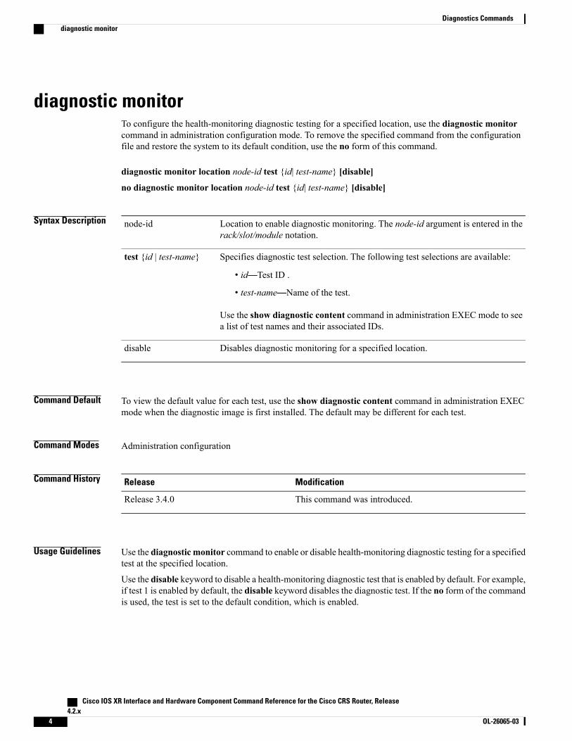
Task ID OperationsTask ID
read, writediag
Examples The following example shows how to enable health-monitoring diagnostic testing for 0/1/cpu0:
RP/0/RP0/CPU0:router(admin-config)# diagnostic monitor location 0/1/cpu0 test 1
Related Commands DescriptionCommand
Displays test information including test ID, test attributes, andsupported coverage test levels for each test and for all components.
show diagnostic content, on page 36
Cisco IOS XR Interface and Hardware Component Command Reference for the Cisco CRS Router, Release 4.2.x
OL-26065-03 5
Diagnostics Commandsdiagnostic monitor

diagnostic monitor intervalTo configure the health-monitoring diagnostic testing for a specified interval for a specified location, use thediagnostic monitor interval command in administration configuration mode. To remove the specifiedcommand from the configuration file and restore the system to its default condition, use the no form of thiscommand.
diagnostic monitor interval location node-id test {id| test-name} number-of-days hour : minutes : seconds. milliseconds
no diagnostic monitor interval location node-id test {id| test-name} number-of-days hour :minutes : seconds. milliseconds
Syntax Description Specifies a location. The node-id argument is entered in therack/slot/module notation.
location node-id
Specifies diagnostic test selection. The following test selections areavailable:
• id—Test ID.
• test-name—Test name .
Use the show diagnostic content command in administration EXECmode to see a list of test names and their associated IDs.
test {id | test-name}
Interval between each test run.
The number-of-days argument specifies the number of days betweentesting. The range is from 0 through 20.
The hour:minutes:seconds.milliseconds argument specifies the interval,where hour is a number in the range from 0 through 23, minutes is anumber in the range from 0 through 59, seconds is a number in the rangefrom 0 through 59, and milliseconds is a number in the range from 0through 999.
number-of-dayshour:minutes:seconds.milliseconds
Command Default To view the default value for each test, use the show diagnostic content command in administration EXECmode when the diagnostic image is first installed. The default may be different for each test.
Command Modes Administration configuration
Command History ModificationRelease
This command was introduced.Release 3.4.0
Cisco IOS XR Interface and Hardware Component Command Reference for the Cisco CRS Router, Release4.2.x
6 OL-26065-03
Diagnostics Commandsdiagnostic monitor interval
Usage Guidelines Use the diagnostic monitor interval command to set the health-monitoring interval of a specified test at thespecified location. The no version of the command resets the interval to the default setting. The diagnosticmonitor command is used to enable health-monitoring.
To specify a physical layer interface module (PLIM) node using the node-id argument, use the followingnotation: rack/PLslot-number/SP. For example, 0/PL1/SP. PLIM diagnostic tests are supported.
Note
Task ID OperationsTask ID
read, writediag
Examples The following example shows how to set the health-monitoring diagnostic testing at an interval of 1 hour, 2minutes, 3 seconds, and 4 milliseconds for 0/1/cpu0:
RP/0/RP0/CPU0:router(admin-config)# diagnostic monitor interval location 0/1/cpu0 test 1 01:2:3.4
Related Commands DescriptionCommand
Configures the health-monitoring diagnostic testing for a specifiedlocation.
diagnostic monitor, on page 4
Displays test information including test ID, test attributes, andsupported coverage test levels for each test and for all components.
show diagnostic content, on page 36
Cisco IOS XR Interface and Hardware Component Command Reference for the Cisco CRS Router, Release 4.2.x
OL-26065-03 7
Diagnostics Commandsdiagnostic monitor interval
diagnostic monitor syslogTo enable the generation of a syslog message when any health monitoring test fails, use the diagnostic monitorsyslog command in administration configuration mode. To remove the specified command from theconfiguration file and restore the system to its default condition, use the no form of this command.
diagnostic monitor syslog
no diagnostic monitor syslog
Syntax Description This command has no keywords or arguments.
Command Default Syslog is disabled.
Command Modes Administration configuration
Command History ModificationRelease
This command was introduced.Release 3.4.0
Usage Guidelines Use the diagnostic monitor syslog command to enable the generation of a syslog message when ahealth-monitoring test fails.
Task ID OperationsTask ID
read, writediag
Examples The following example shows how to enable the generation of syslog messages:
RP/0/RP0/CPU0:router(admin-config)# diagnostic monitor syslog
Related Commands DescriptionCommand
Displays test information including test ID, test attributes, andsupported coverage test levels for each test and for all components.
show diagnostic content, on page 36
Cisco IOS XR Interface and Hardware Component Command Reference for the Cisco CRS Router, Release4.2.x
8 OL-26065-03
Diagnostics Commandsdiagnostic monitor syslog
diagnostic monitor thresholdTo configure the health-monitoring diagnostic testing failure threshold, use the diagnostic monitor thresholdcommand in administration configuration mode. To remove the specified command from the configurationfile and restore the system to its default condition, use the no form of this command.
diagnostic monitor threshold location node-id test {id| test-name} failure count failures
no diagnostic monitor threshold location node-id test {id| test-name} failure count failures
Syntax Description Specifies a location. The node-id argument is entered in the rack/slot/modulenotation.
location node-id
Specifies diagnostic test selection. The following test selections are available:
• id—Test ID.
• test-name—Test name .
Use the show diagnostic content command in administration EXEC modeto see a list of test names and their associated IDs.
test {id | test-name}
Specifies the number of allowable test failures. Range is 1 to 99.failure count failures
Command Default To view the default value for each test, use the show diagnostic content command in administration EXECmode when the diagnostic image is first installed. The default can be different for each test.
Command Modes Administration configuration
Command History ModificationRelease
This command was introduced.Release 3.4.0
Usage Guidelines Use the diagnostic monitor threshold command to specify health-monitoring diagnostic testing failurethreshold.
To specify a physical layer interface module (PLIM) node using the node-id argument, use the followingnotation: rack/PLslot-number/SP. For example, 0/PL1/SP. PLIM diagnostic tests are supported.
Note
Cisco IOS XR Interface and Hardware Component Command Reference for the Cisco CRS Router, Release 4.2.x
OL-26065-03 9
Diagnostics Commandsdiagnostic monitor threshold

Task ID OperationsTask ID
read, writediag
Examples The following example shows how to set the failure threshold to 35 test failures for all tests for 0/1/cpu0:
RP/0/RP0/CPU0:router(admin-config)# diagnostic monitor threshold location 0/1/cpu0 test allfailure count 35
Related Commands DescriptionCommand
Displays test information including test ID, test attributes, andsupported coverage test levels for each test and for all components.
show diagnostic content, on page 36
Cisco IOS XR Interface and Hardware Component Command Reference for the Cisco CRS Router, Release4.2.x
10 OL-26065-03
Diagnostics Commandsdiagnostic monitor threshold
diagnostic ondemand action-on-failureTo set when to stop test execution for a diagnostic start command, use the diagnostic ondemandaction-on-failure command in Admin EXECmode. This command is used in conjunction with the diagnosticondemand iteration command.
diagnostic ondemand action-on-failure {continue [ failure-count ]| stop}
Syntax Description Specifies that test execution continues until all iterations are complete, no matter howmany failures are encountered.
continue
(Optional) Specifies that test execution continues until the number of failures reachesthe specified failure-count. Range is 0 to 65534. A failure-count of 0 indicates to notstop execution until all iterations are complete, no matter how many failures areencountered.
failure-count
Stops execution immediately when the first test failure occurs.stop
Command Default failure-count: 0
Command Modes Admin EXEC mode
Command History ModificationRelease
This command was introduced.Release 3.5.0
Usage Guidelines Use the diagnostic ondemand action-on-failure command to specify whether or when to stop test executionif a test fails. This command is used in conjunction with the diagnostic ondemand iterations command.
Task ID OperationsTask ID
executediag
Examples The following example shows how to set the test failure action to stop:
RP/0/RP0/CPU0:router(admin)# diagnostic ondemand action-on-failure stop
Cisco IOS XR Interface and Hardware Component Command Reference for the Cisco CRS Router, Release 4.2.x
OL-26065-03 11
Diagnostics Commandsdiagnostic ondemand action-on-failure

Related Commands DescriptionCommand
Sets the number of times to repeat execution of thediagnostic test.
diagnostic ondemand iterations, on page 13
Runs a specified diagnostic test.diagnostic start, on page 17
Cisco IOS XR Interface and Hardware Component Command Reference for the Cisco CRS Router, Release4.2.x
12 OL-26065-03
Diagnostics Commandsdiagnostic ondemand action-on-failure

diagnostic ondemand iterationsTo set the number of times to repeat execution of the tests specified by the diagnostic start command, usethe diagnostic ondemand iterations command in Admin EXEC mode.
diagnostic ondemand iterations count
Syntax Description Number of times to repeat the specified on-demand tests. Range is 1 to 999.count
Command Default count: 1
Command Modes Admin EXEC mode
Command History ModificationRelease
This command was introduced.Release 3.5.0
Usage Guidelines Use the diagnostic ondemand iterations command to specify the number of times the specified on-demandtests run. The on-demand tests are specified using the diagnostic start command.
Task ID OperationsTask ID
executediag
Examples The following example shows how to set the number of iterations to 12:
RP/0/RP0/CPU0:router(admin)# diagnostic ondemand iterations 12
Related Commands DescriptionCommand
Sets when to stop test execution for a diagnostic test.diagnostic ondemand action-on-failure, on page 11
Runs a specified diagnostic test.diagnostic start, on page 17
Cisco IOS XR Interface and Hardware Component Command Reference for the Cisco CRS Router, Release 4.2.x
OL-26065-03 13
Diagnostics Commandsdiagnostic ondemand iterations
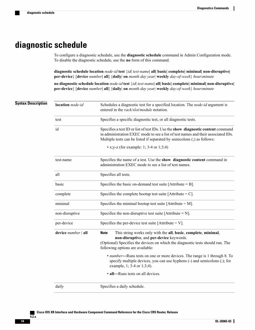
diagnostic scheduleTo configure a diagnostic schedule, use the diagnostic schedule command in Admin Configuration mode.To disable the diagnostic schedule, use the no form of this command.
diagnostic schedule location node-id test {id| test-name| all| basic| complete| minimal| non-disruptive|per-device} [device number| all] {daily| on month day year| weekly day-of-week} hour:minute
no diagnostic schedule location node-id test {id| test-name| all| basic| complete| minimal| non-disruptive|per-device} [device number| all] {daily| on month day year| weekly day-of-week} hour:minute
Syntax Description Schedules a diagnostic test for a specified location. The node-id argument isentered in the rack/slot/module notation.
location node-id
Specifies a specific diagnostic test, or all diagnostic tests.test
Specifies a test ID or list of test IDs. Use the show diagnostic content commandin administration EXECmode to see a list of test names and their associated IDs.Multiple tests can be listed if separated by semicolons (;) as follows:
• x;y-z (for example: 1; 3-4 or 1;3;4)
id
Specifies the name of a test. Use the show diagnostic content command inadministration EXEC mode to see a list of test names.
test-name
Specifies all tests.all
Specifies the basic on-demand test suite [Attribute = B].basic
Specifies the complete bootup test suite [Attribute = C].complete
Specifies the minimal bootup test suite [Attribute = M].minimal
Specifies the non-disruptive test suite [Attribute = N].non-disruptive
Specifies the per-device test suite [Attribute = V].per-device
This string works only with the all, basic, complete, minimal,non-disruptive, and per-device keywords.
Note
(Optional) Specifies the devices on which the diagnostic tests should run. Thefollowing options are available:
• number—Runs tests on one or more devices. The range is 1 through 8. Tospecify multiple devices, you can use hyphens (-) and semicolons (;); forexample, 1; 3-4 or 1;3;4).
• all—Runs tests on all devices.
device number | all
Specifies a daily schedule.daily
Cisco IOS XR Interface and Hardware Component Command Reference for the Cisco CRS Router, Release4.2.x
14 OL-26065-03
Diagnostics Commandsdiagnostic schedule

Schedules an exact date.on month day year
Specifies a weekly schedule with a set day of the week. Enter the name of a dayof the week or a number that specifies a day of the week in the range from 0through 6.
weekly day-of-week
Scheduled start time, where hour is a number in the range from 0 through 23,and minute is a number in the range from 0 through 59.
hour:minute
Command Default No default behavior or values
Command Modes Admin Configuration mode
Command History ModificationRelease
This command was introduced.Release 3.3.0
Usage Guidelines
To specify a physical layer interface module (PLIM) node using the node-id argument, use the followingnotation: rack/PLslot-number/SP. For example, 0/PL1/SP. PLIM diagnostic tests are supported.
Note
For more information about running Cisco IOS XR diagnostics, refer to Cisco IOS XR Diagnostics.
Task ID OperationsTask ID
read, writediag
Examples The following example shows how to schedule all diagnostic tests for location 0/0/CPU0 every day at 12:30pm:
RP/0/RP0/CPU0:router# adminRP/0/RP0/CPU0:router(admin)# configureRP/0/RP0/CPU0:router(admin-config)# diagnostic schedule location 0/0/CPU0 test all daily12:30
The following example shows how to schedule all bootup tests for device 1 every Sunday at 12:30 pm:
RP/0/RP0/CPU0:router# adminRP/0/RP0/CPU0:router(admin)# configureRP/0/RP0/CPU0:router(admin-config)# diagnostic schedule location 0/0/CPU0 test all dailycomplete device 1 weekly 12:30
Cisco IOS XR Interface and Hardware Component Command Reference for the Cisco CRS Router, Release 4.2.x
OL-26065-03 15
Diagnostics Commandsdiagnostic schedule

Related Commands DescriptionCommand
Displays the current scheduled diagnostic tasks.show diagnostic schedule, on page 47
Cisco IOS XR Interface and Hardware Component Command Reference for the Cisco CRS Router, Release4.2.x
16 OL-26065-03
Diagnostics Commandsdiagnostic schedule

diagnostic startTo run a specified diagnostic test, use the diagnostic start command in Admin EXEC mode.
diagnostic start location node-id test {id| test-name| all| basic| complete| minimal| non-disruptive|per-device} [device number| all]
Syntax Description Runs diagnostic testing for a specified location. The node-id argument is enteredin the rack/slot/module notation.
location node-id
Specifies a specific diagnostic test, or all diagnostic tests.test
Test ID or list of test IDs. Use the show diagnostic content command inadministration EXEC mode to see a list of test names and their associated IDs.Multiple tests can be listed if separated by semicolons (;) as follows:
• x;y-z (for example: 1; 3-4 or 1;3;4)
id
Name of the test. Use the show diagnostic content command in administrationEXEC mode to see a list of test names.
test-name
Specifies all tests.all
Specifies the basic on-demand test suite [Attribute = B].basic
Specifies the complete bootup test suite [Attribute = C].complete
Specifies the minimal bootup test suite [Attribute = M].minimal
Specifies the nondisruptive test suite [Attribute = N].non-disruptive
Specifies the per-device test suite [Attribute = V].per-device
This string works only with the all, basic, complete, minimal,non-disruptive, and per-device keywords.
Note
(Optional) Specifies the devices on which the diagnostic tests should start. Thefollowing options are available:
• number—Start tests on one or more devices. The range is 1 through 8. Tospecify multiple devices, you can use hyphens (-) and semicolons (;); forexample, 1; 3-4 or 1;3;4).
• all—Starts tests on all devices.
device number | all
Command Default No default behavior or values
Cisco IOS XR Interface and Hardware Component Command Reference for the Cisco CRS Router, Release 4.2.x
OL-26065-03 17
Diagnostics Commandsdiagnostic start

Command Modes Admin EXEC mode
Command History ModificationRelease
This command was introduced.Release 3.3.0
The per-device keyword was added.Release 3.5.0
Usage Guidelines Use the diagnostic start command to run a diagnostic test on a specified card.
To specify a physical layer interface module (PLIM) node using the node-id argument, use the followingnotation: rack/PLslot-number/SP. For example, 0/PL1/SP. PLIM diagnostic tests are supported.
Note
For more information about running Cisco IOS XR diagnostics, refer to Cisco IOS XR Diagnostics.
Task ID OperationsTask ID
executediag
Examples The following example shows how to start a suite of basic diagnostic tests for a specified location:
RP/0/RP0/CPU0:router# adminRP/0/RP0/CPU0:router(admin)# diagnostic start location 0/0/CPU0 test basic
The following example shows how to start a suite of minimal bootup tests for devices 1 through 7 at thespecified location:
RP/0/RP0/CPU0:router# adminRP/0/RP0/CPU0:router(admin)# diagnostic start location 0/0/CPU0 test minimal devices 1-7
Related Commands DescriptionCommand
Stops the diagnostic testing in progress on a node.diagnostic stop, on page 19
Cisco IOS XR Interface and Hardware Component Command Reference for the Cisco CRS Router, Release4.2.x
18 OL-26065-03
Diagnostics Commandsdiagnostic start
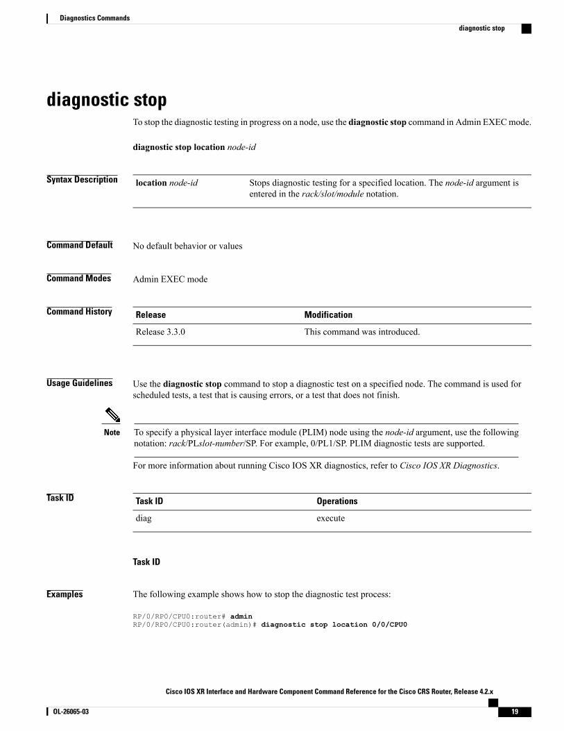
diagnostic stopTo stop the diagnostic testing in progress on a node, use the diagnostic stop command in Admin EXECmode.
diagnostic stop location node-id
Syntax Description Stops diagnostic testing for a specified location. The node-id argument isentered in the rack/slot/module notation.
location node-id
Command Default No default behavior or values
Command Modes Admin EXEC mode
Command History ModificationRelease
This command was introduced.Release 3.3.0
Usage Guidelines Use the diagnostic stop command to stop a diagnostic test on a specified node. The command is used forscheduled tests, a test that is causing errors, or a test that does not finish.
To specify a physical layer interface module (PLIM) node using the node-id argument, use the followingnotation: rack/PLslot-number/SP. For example, 0/PL1/SP. PLIM diagnostic tests are supported.
Note
For more information about running Cisco IOS XR diagnostics, refer to Cisco IOS XR Diagnostics.
Task ID OperationsTask ID
executediag
Task ID
Examples The following example shows how to stop the diagnostic test process:
RP/0/RP0/CPU0:router# adminRP/0/RP0/CPU0:router(admin)# diagnostic stop location 0/0/CPU0
Cisco IOS XR Interface and Hardware Component Command Reference for the Cisco CRS Router, Release 4.2.x
OL-26065-03 19
Diagnostics Commandsdiagnostic stop

Related Commands DescriptionCommand
Runs a specified diagnostic test.diagnostic start, on page 17
Cisco IOS XR Interface and Hardware Component Command Reference for the Cisco CRS Router, Release4.2.x
20 OL-26065-03
Diagnostics Commandsdiagnostic stop

diagnostic test-parametersThe FabricUcastMcastTest diagnostic test is used to periodically verify the fabric connectivity to all fabricdestinations (RP, LC, DRP nodes) in a single or multi-chassis system. Automatic reload and shutdown as aresult of a single -node failure is disabled by default. To enable this feature, set the parameters of theFabricUcastMcast test by setting one or more of the optional parameters of the diagnostic test-parametersFabricUcastMcastTest command in Admin EXEC mode.
diagnostic test-parametersFabricUcastMcastTest[single-DRP-node-failure|single-LC-node-failure|single-RP-node-failure]<failure-type|reload threshold | shutdown threshold>
Syntax Description (Optional) Enters the mode to set the parameters for the FabricUcastMcast Testwhen a single node failure occurs as a result of a DRP failure.
single-DRP-node-failure
(Optional) Enters the mode to set the parameters for the FabricUcastMcast Testwhen a single node failure occurs as a result of a line card (LC) failure.
single-LC-node-failure
(Optional) Enters the mode to set the parameters for the FabricUcastMcast Testwhen a single node failure occurs as a result of a route processor (RP) failure.
single-RP-node-failure
(Optional) Specifies the type of ping result to use for triggering node reload orshutdown. Options are:
• unicast-only-Multicast ping results are ignored.
• multicast-only-Unicast ping results are ignored.
Default is both unicast and multicast ping results are used.
failure-type
(Optional) Specifies the number of consecutive single-node failures that triggerthe reload of a node. Range is 2 through 255. This value must be less than theshutdown threshold for the same node type.
reload threshold
(Optional) Specifies the number of consecutive single-node failures that triggerthe shutdown of a node. Range is 2 through 255. This value must be greater thanthe reload threshold for the same node type.
shutdown threshold
Command Default None
Command Modes Admin EXEC mode
Command History ModificationRelease
This command was introduced.Release 4.2.1
Cisco IOS XR Interface and Hardware Component Command Reference for the Cisco CRS Router, Release 4.2.x
OL-26065-03 21
Diagnostics Commandsdiagnostic test-parameters

Usage Guidelines No specific guidelines impact the use of this command.
Task ID OperationsTask ID
read, writediag
Examples The following example shows how to set a node for automatic reload and shutdown when theFabricUcastMcastTest results return single node failure. This is a result of line card failures for only multicasttraffic:
RP/0/RP0/CPU0:router# adminRP/0/RP0/CPU0:router(admin)# configurationRP/0/RP0/CPU0:router(admin-config)# diagnostic test-parametersRP/0/RP0/CPU0:router(admin-config-diag-test-params)#FabricUcastMcastTestRP/0/RP0/CPU0:router(admin-config-FabricUcastMcastTest)#single-LC-node-failureRP/0/RP0/CPU0:router(admin-config-FabricUcastMcastTest-LC)failure-type multicast-onlyRP/0/RP0/CPU0:router(admin-config-FabricUcastMcastTest-LC)reload threshold 5RP/0/RP0/CPU0:router(admin-config-FabricUcastMcastTest-LC)shutdown threshold 6RP/0/RP0/CPU0:router(admin-config-FabricUcastMcastTest-LC)commitWhen a single-node failure is detected, the following syslog messages are logged:RP/0/RP1/CPU0:Jan 27 07:58:58.364 : online_diag_rp[276]: %DIAG-XR_DIAG-3-ERROR : (U)Fabric Ping Failure, 1 of 3 nodes failed(L): 0/3/CPU0RP/0/RP1/CPU0:Jan 27 07:58:58.802 : online_diag_rp[276]: %DIAG-XR_DIAG-3-ERROR : (U) FIM:
single-node failure detected - 0/3/CPU0consecutive ucast/mcast failures: 15/0
When the reload threshold is reached, the following syslog message is logged prior to the reload:RP/0/RP1/CPU0:Jan 27 07:58:58.803 : online_diag_rp[276]: %DIAG-XR_DIAG-6-INFO :reloadthreshold 15 crossed, reloading 0/3/CPU0
When the shutdown threshold is reached, the following syslog messages are logged:RP/0/RP1/CPU0:Jan 27 08:11:02.104 : online_diag_rp[276]: %DIAG-XR_DIAG-6-INFO : shutdownthreshold 10 crossed, shutting down 0/3/CPU0RP/0/RP1/CPU0:Jan 27 08:11:02.137 : online_diag_rp[276]:%PLATFORM-SHELFMGR-6-BRINGDOWN_REQUEST_LIB : Requesting node 0/3/CPU0 to be shutdown.reason: [diag fabric ping failure]RP/0/RP0/CPU0:Jan 27 08:11:02.136 : shelfmgr[306]: %PLATFORM-SHELFMGR-6-BRINGDOWN_REQUEST
: process online_diag_rp running on node0_RP1_CPU0 requested node 0/3/CPU0 to be shutdown.
reason: [diag fabric ping failure]
Cisco IOS XR Interface and Hardware Component Command Reference for the Cisco CRS Router, Release4.2.x
22 OL-26065-03
Diagnostics Commandsdiagnostic test-parameters
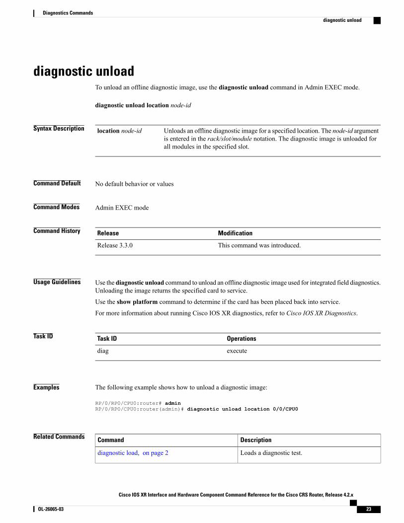
diagnostic unloadTo unload an offline diagnostic image, use the diagnostic unload command in Admin EXEC mode.
diagnostic unload location node-id
Syntax Description Unloads an offline diagnostic image for a specified location. The node-id argumentis entered in the rack/slot/module notation. The diagnostic image is unloaded forall modules in the specified slot.
location node-id
Command Default No default behavior or values
Command Modes Admin EXEC mode
Command History ModificationRelease
This command was introduced.Release 3.3.0
Usage Guidelines Use the diagnostic unload command to unload an offline diagnostic image used for integrated field diagnostics.Unloading the image returns the specified card to service.
Use the show platform command to determine if the card has been placed back into service.
For more information about running Cisco IOS XR diagnostics, refer to Cisco IOS XR Diagnostics.
Task ID OperationsTask ID
executediag
Examples The following example shows how to unload a diagnostic image:
RP/0/RP0/CPU0:router# adminRP/0/RP0/CPU0:router(admin)# diagnostic unload location 0/0/CPU0
Related Commands DescriptionCommand
Loads a diagnostic test.diagnostic load, on page 2
Cisco IOS XR Interface and Hardware Component Command Reference for the Cisco CRS Router, Release 4.2.x
OL-26065-03 23
Diagnostics Commandsdiagnostic unload

DescriptionCommand
Displays information and status of each node in thesystem.
show platform
Cisco IOS XR Interface and Hardware Component Command Reference for the Cisco CRS Router, Release4.2.x
24 OL-26065-03
Diagnostics Commandsdiagnostic unload
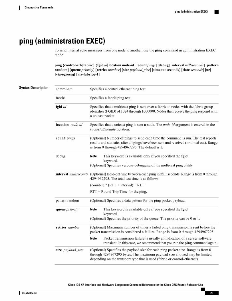
ping (administration EXEC)To send internal echo messages from one node to another, use the ping command in administration EXECmode.
ping {control-eth| fabric} {fgid id| location node-id} [count pings] [debug] [intervalmilliseconds] [patternrandom] [queue priority] [retries number] [size payload_size] [timeout seconds] [tlate seconds] [uc][via-egressq] [via-fabricq-1]
Syntax Description Specifies a control ethernet ping test.control-eth
Specifies a fabric ping test.fabric
Specifies that a multicast ping is sent over a fabric to nodes with the fabric groupidentifier (FGID) of 1024 through 1000000. Nodes that receive the ping respond witha unicast packet.
fgid id
Specifies that a unicast ping is sent a node. The node-id argument is entered in therack/slot/module notation.
location node-id
(Optional) Number of pings to send each time the command is run. The test reportsresults and statistics after all pings have been sent and received (or timed out). Rangeis from 0 through 4294967295. The default is 1.
count pings
This keyword is available only if you specified the fgidkeyword.
Note
(Optional) Specifies verbose debugging of the multicast ping utility.
debug
(Optional) Hold-off time between each ping in milliseconds. Range is from 0 through4294967295. The total test time is as follows:
(count-1) * (RTT + interval) + RTT
RTT = Round Trip Time for the ping.
interval milliseconds
(Optional) Specifies a data pattern for the ping packet payload.pattern random
This keyword is available only if you specified the fgidkeyword.
Note
(Optional) Specifies the priority of the queue. The priority can be 0 or 1.
queue priority
(Optional) Maximum number of times a failed ping transmission is sent before thepacket transmission is considered a failure. Range is from 0 through 4294967295.
Packet transmission failure is usually an indication of a server softwaretransient. In this case, we recommend that you run the ping command again.
Note
retries number
(Optional) Specifies the payload size for each ping packet size. Range is from 0through 4294967295 bytes. The maximum payload size allowed may be limited,depending on the transport type that is used (fabric or control-ethernet).
size payload_size
Cisco IOS XR Interface and Hardware Component Command Reference for the Cisco CRS Router, Release 4.2.x
OL-26065-03 25
Diagnostics Commandsping (administration EXEC)
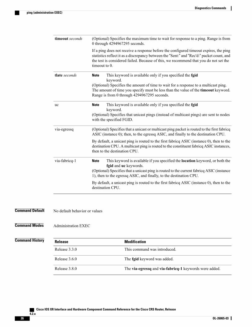
(Optional) Specifies the maximum time to wait for response to a ping. Range is from0 through 4294967295 seconds.
If a ping does not receive a response before the configured timeout expires, the pingstatistics reflect it as a discrepancy between the “Sent:” and “Rec'd:” packet count, andthe test is considered failed. Because of this, we recommend that you do not set thetimeout to 0.
timeout seconds
This keyword is available only if you specified the fgidkeyword.
Note
(Optional) Specifies the amount of time to wait for a response to a multicast ping.The amount of time you specify must be less than the value of the timeout keyword.Range is from 0 through 4294967295 seconds.
tlate seconds
This keyword is available only if you specified the fgidkeyword.
Note
(Optional) Specifies that unicast pings (instead of multicast pings) are sent to nodeswith the specified FGID.
uc
(Optional) Specifies that a unicast or multicast ping packet is routed to the first fabricqASIC (instance 0); then, to the egressq ASIC, and finally to the destination CPU.
By default, a unicast ping is routed to the first fabricq ASIC (instance 0), then to thedestination CPU. Amulticast ping is routed to the constituent fabricq ASIC instances,then to the destination CPU.
via-egressq
This keyword is available if you specified the location keyword, or both thefgid and uc keywords.
Note
(Optional) Specifies that a unicast ping is routed to the current fabricq ASIC (instance1), then to the egressq ASIC, and finally, to the destination CPU.
By default, a unicast ping is routed to the first fabricq ASIC (instance 0), then to thedestination CPU.
via-fabricq-1
Command Default No default behavior or values
Command Modes Administration EXEC
Command History ModificationRelease
This command was introduced.Release 3.3.0
The fgid keyword was added.Release 3.6.0
The via-egressq and via-fabricq-1 keywords were added.Release 3.8.0
Cisco IOS XR Interface and Hardware Component Command Reference for the Cisco CRS Router, Release4.2.x
26 OL-26065-03
Diagnostics Commandsping (administration EXEC)

Usage Guidelines When you enter the ping command, a ping is sent to the node at the specified location or to nodes with thespecified FGID. The received response is compared byte-by-byte to the sent packet. If a ping response is notreceived before the specified time-out, or if the ping response does not match the transmitted ping, the pingis considered failed.
A node that is unreachable or intermittently working impacts the total run time for the test as follows:
(received_packet_count * RTT + lost_packet_count * timeout + (count-1) * interval)
Line cards have two fabricq ASICs and an egressq ASIC. From the first fabricq ASIC (instance 0), the CPUcan be reached directly or via the egressq ASIC. From the second fabricq ASIC (instance 1), the CPU can bereached only via the egressq ASIC. In other words, no direct packet path exists between instance 1 and theCPU.
The route processor (RP) and distributed route processor (DRP) cards have only one fabricq ASIC per node(CPU) and no egressq ASIC. Therefore, a fabric ping on an RP or DRP destination specified with thevia-egressq or via-fabricq-1 keyword fails.
Task ID OperationsTask ID
executediag
Examples The following example shows sample output from a control-ethernet ping to an SP node in slot 0/0:
RP/0/RP0/CPU0:router# adminRP/0/RP0/CPU0:router(admin)# ping control-eth location 0/0/SP count 5
Src node: 529 : 0/RP0/CPU0Dest node: 0 : 0/0/SPLocal node: 529 : 0/RP0/CPU0Packet cnt: 5 Packet size: 128 Payload ptn type: default (0)Hold-off (ms): 300 Time-out(s): 2 Max retries: 5Destination node has MAC addr 5246.4800.0000
Running CE node ping.Please wait...Src: 529:, Dest: 0, Sent: 5, Rec'd: 5, Mismatched: 0Min/Avg/Max RTT: 0/200/1000CE node ping succeeded for node: 0
The following example shows a fabric ping from the active RP to the active RP. In this example, the pingcontains 72 packets of 1 kilobyte each. This command performs a good coverage test of the entire switchfabric:
RP/0/RP0/CPU0:router# adminRP/0/RP0/CPU0:router(admin)# ping fabric location 0/RP0/CPU0 count 72 size 1024
Src node: 529 : 0/RP0/CPU0Dest node: 529 : 0/RP0/CPU0Local node: 529 : 0/RP0/CPU0Packet cnt: 72 Packet size: 1024 Payload ptn type: default (0)Hold-off (ms): 300 Time-out(s): 2 Max retries: 5
Running Fabric node ping.Please wait...
Cisco IOS XR Interface and Hardware Component Command Reference for the Cisco CRS Router, Release 4.2.x
OL-26065-03 27
Diagnostics Commandsping (administration EXEC)

Src: 529:, Dest: 529, Sent: 72, Rec'd: 72, Mismatched: 0Min/Avg/Max RTT: 3000/3013/4000Fabric node ping succeeded for node: 529
The following example shows a ping to a control Ethernet node that has a problem or does not exist:
RP/0/RP0/CPU0:router# adminRP/0/RP0/CPU0:router(admin)# ping control-eth location 0/1/CPU0 count 3
Src node: 529 : 0/RP0/CPU0Dest node: 17 : 0/1/CPU0Local node: 529 : 0/RP0/CPU0Packet cnt: 3 Packet size: 128 Payload ptn type: default (0)Hold-off (ms): 300 Time-out(s): 2 Max retries: 5Destination node has MAC addr 5246.4800.0011
Running CE node ping.Please wait...Src: 529:, Dest: 17, Sent: 3, Rec'd: 0, Mismatched: 0Requested ping failed for node: 17
The following example shows how to send a multicast fabric ping to nodes with the FGID of 1024. The nodethat sent the multicast ping waits 1 second for a response from each node.
RP/0/RP0/CPU0:router# adminRP/0/RP0/CPU0:router(admin)# ping fabric fgid 1024 tlate 1
Src node: 513 : 0/RP0/CPU0fgid: 1024Local node: 513 : 0/RP0/CPU0Packet cnt: 1 Packet size: 128 Payload ptn type: default (0)Hold-off (ms): 1 Time-out(s): 2 Max retries: 5DelayTimeout: 1 Priority: HighRunning Fabric node ping.Please wait...
Multicast (Pinging fgid) ...
Node Sent Rcv. Late Lost______________________________________________________________0/1/CPU0 (0x11:17) 1 1 0 00/4/CPU0 (0x41:65) 1 1 0 00/4/CPU1 (0x42:66) 1 1 0 00/6/CPU0 (0x61:97) 1 1 0 0
0/RP0/CPU0 (0x201:513) 1 1 0 00/RP1/CPU0 (0x211:529) 1 1 0 0
diag_ping: All 6 nodes responded to all 1 pings
The following example shows how to send a multicast fabric ping to nodes with the FGID of 1024. The pingpackets are routed from the first fabricq ASIC (instance 0) to the destination CPU via the egressq ASIC. Thepings to the two line cards (0/1/CPU0 and 0/6/CPU0) succeeded, while the pings to the RPs (0/RP0/CPU0and 0/RP1/CPU0) and DRPs (0/4/CPU0 and 0/4/CPU1) failed because they do not have an egressq ASIC.
RP/0/RP0/CPU0:router# adminRP/0/RP0/CPU0:router(admin)# ping fabric fgid 1024 count 10 via-egressq
Src node: 513 : 0/RP0/CPU0fgid: 1024Local node: 513 : 0/RP0/CPU0Packet cnt: 10 Packet size: 128 Payload ptn type: default (0)Hold-off (ms): 1 Time-out(s): 2 Max retries: 5DelayTimeout: 1 Priority: HighReaching destination CPUs via egressq
Running Fabric node ping.Please wait...
Multicast (Pinging fgid) ...
Cisco IOS XR Interface and Hardware Component Command Reference for the Cisco CRS Router, Release4.2.x
28 OL-26065-03
Diagnostics Commandsping (administration EXEC)
Node Sent Rcv. Late Lost______________________________________________________________0/1/CPU0 (0x11:17) 10 10 0 00/4/CPU0 (0x41:65) 10 0 0 100/4/CPU1 (0x42:66) 10 0 0 100/6/CPU0 (0x61:97) 10 10 0 0
0/RP0/CPU0 (0x201:513) 10 0 0 100/RP1/CPU0 (0x211:529) 10 0 0 10
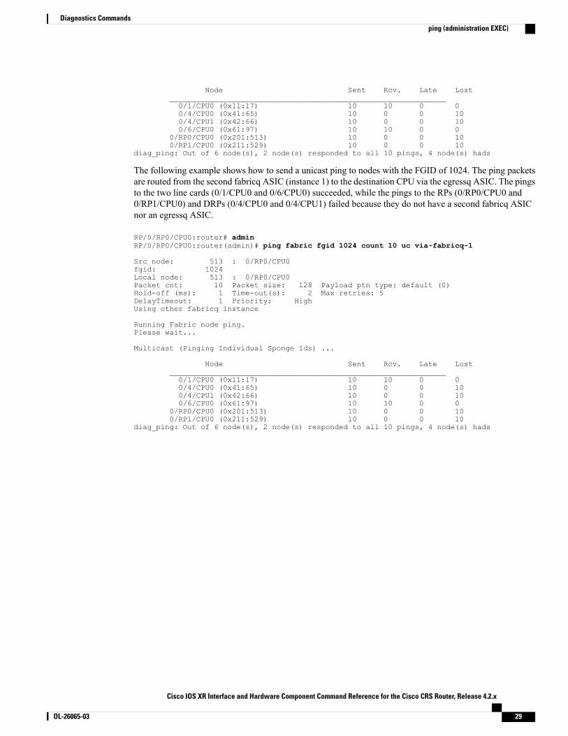
diag_ping: Out of 6 node(s), 2 node(s) responded to all 10 pings, 4 node(s) hads
The following example shows how to send a unicast ping to nodes with the FGID of 1024. The ping packetsare routed from the second fabricq ASIC (instance 1) to the destination CPU via the egressq ASIC. The pingsto the two line cards (0/1/CPU0 and 0/6/CPU0) succeeded, while the pings to the RPs (0/RP0/CPU0 and0/RP1/CPU0) and DRPs (0/4/CPU0 and 0/4/CPU1) failed because they do not have a second fabricq ASICnor an egressq ASIC.
RP/0/RP0/CPU0:router# adminRP/0/RP0/CPU0:router(admin)# ping fabric fgid 1024 count 10 uc via-fabricq-1
Src node: 513 : 0/RP0/CPU0fgid: 1024Local node: 513 : 0/RP0/CPU0Packet cnt: 10 Packet size: 128 Payload ptn type: default (0)Hold-off (ms): 1 Time-out(s): 2 Max retries: 5DelayTimeout: 1 Priority: HighUsing other fabricq instance
Running Fabric node ping.Please wait...
Multicast (Pinging Individual Sponge Ids) ...
Node Sent Rcv. Late Lost______________________________________________________________0/1/CPU0 (0x11:17) 10 10 0 00/4/CPU0 (0x41:65) 10 0 0 100/4/CPU1 (0x42:66) 10 0 0 100/6/CPU0 (0x61:97) 10 10 0 0
0/RP0/CPU0 (0x201:513) 10 0 0 100/RP1/CPU0 (0x211:529) 10 0 0 10
diag_ping: Out of 6 node(s), 2 node(s) responded to all 10 pings, 4 node(s) hads
Cisco IOS XR Interface and Hardware Component Command Reference for the Cisco CRS Router, Release 4.2.x
OL-26065-03 29
Diagnostics Commandsping (administration EXEC)

show diagTo display details about the hardware and software on each node in a router, use the show diag command inthe appropriate mode.
EXEC Mode
show diag [ node-id ] [details| eeprom-info| power-regs| summary]
Administration EXEC Mode
show diag [ node-id ] [chassis| fans| power-supply] [details| eeprom-info| power-regs| summary]
Syntax Description (Optional) Displays a summary of the installed hardware.summary
(Optional) Identifies the node for which you want to display information. Thenode-id argument is expressed in the rack/slot/module notation.
node-id
(Optional) Displays EEPROM information for the specified node or component(chassis, fan, or power supply).
eeprom-info
(Optional) Displays power register information for the specified node.power-regs
(Optional) Displays information about the chassis.chassis
(Optional) Displays information about the fan trays.fans
(Optional) Displays information about the power supply.power-supply
Command Default Hardware and software information for all nodes installed in the router is displayed
Command Modes EXEC
Administration EXEC
Command History ModificationRelease
This command was introduced.Release 2.0
Command output was modified to display the last diagnostic resultfor a card.
Release 3.2
Cisco IOS XR Interface and Hardware Component Command Reference for the Cisco CRS Router, Release4.2.x
30 OL-26065-03
Diagnostics Commandsshow diag
Usage Guidelines The show diag command displays detailed information on the hardware components for each node, and onthe status of the software running on each node.
Task ID OperationsTask ID
readsysmgr
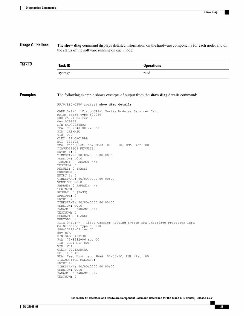
Examples The following example shows excerpts of output from the show diag details command:
RP/0/RP0/CPU0:router# show diag details
CARD 0/1/* : Cisco CRS-1 Series Modular Services CardMAIN: board type 500060800-25021-05 rev B0dev 079239S/N SAD0925050JPCA: 73-7648-08 rev B0PID: CRS-MSCVID: V02CLEI: IPUCAC1BAAECI: 132502RMA: Test Hist: ab, RMA#: 00-00-00, RMA Hist: 00DIAGNOSTICS RESULTS:ENTRY 1: 0TIMESTAMP: 00/00/0000 00:00:00VERSION: v0.0PARAM1: 0 PARAM2: n/aTESTNUM: 0RESULT: 0 (PASS)ERRCODE: 0ENTRY 2: 0TIMESTAMP: 00/00/0000 00:00:00VERSION: v0.0PARAM1: 0 PARAM2: n/aTESTNUM: 0RESULT: 0 (PASS)ERRCODE: 0ENTRY 3: 0TIMESTAMP: 00/00/0000 00:00:00VERSION: v0.0PARAM1: 0 PARAM2: n/aTESTNUM: 0RESULT: 0 (PASS)ERRCODE: 0PLIM 0/PL1/* : Cisco Carrier Routing System SPA Interface Processor CardMAIN: board type 580070800-23819-03 rev C0dev N/AS/N SAD09410538PCA: 73-8982-06 rev C0PID: CRS1-SIP-800VID: V01CLEI: COUIAAMCAAECI: 134912RMA: Test Hist: ab, RMA#: 00-00-00, RMA Hist: 00DIAGNOSTICS RESULTS:ENTRY 1: 0TIMESTAMP: 00/00/0000 00:00:00VERSION: v0.0PARAM1: 0 PARAM2: n/aTESTNUM: 0
Cisco IOS XR Interface and Hardware Component Command Reference for the Cisco CRS Router, Release 4.2.x
OL-26065-03 31
Diagnostics Commandsshow diag

RESULT: 0 (PASS)ERRCODE: 0ENTRY 2: 0TIMESTAMP: 00/00/0000 00:00:00VERSION: v0.0PARAM1: 0 PARAM2: n/aTESTNUM: 0RESULT: 0 (PASS)ERRCODE: 0ENTRY 3: 0TIMESTAMP: 00/00/0000 00:00:00VERSION: v0.0PARAM1: 0 PARAM2: n/aTESTNUM: 0RESULT: 0 (PASS)ERRCODE: 0Interface port config: 0 PortsOptical reach type: UnknownConnector type: MT-PNODE 0/1/CPU0Node State : IOS XR RUNPLD: Motherboard: 0x0025, Processor: 0xda13, Power: N/AMONLIB: QNXFFS Monlib Version 3.1ROMMON: Version 1.51(20080807:092259) [CRS-1 ROMMON]CPU0: ASMP, CPU1: N/ASPEED: OSC Speed: 100 Mhz, CPU Speed: 800 MhzBUS Speed: 100 Mhz, MEM Speed: 100 MhzMEM Size: 1024 MbytesSPA 0/1/0 : 4-port OC3/STM1 POS Shared Port AdapterMAIN: board type 044068-2169-01 rev C0dev N/AS/N JAB093305VCPCA: 73-9313-04 rev B0PID: SPA-4XOC3-POSVID: V01CLEI: IPUIAFNRAANode State : OK...
The output displayed for the show diag details command is the most comprehensive output displayed forshow diag command variations. All other variations show a subset of the fields displayed except for the showdiag chassis, show diag fans, and show diag power-supply commands, which also enable you to displayEEPROM information.
Rack 0 - Cisco CRS-1 Series 8 Slots Line Card Chassis00: 03 00 01 E4 43 52 53 2D 38 2D 4C 43 43 00 00 00 ....CRS-8-LCC...10: 00 00 00 00 00 00 00 00 00 00 00 00 00 00 00 00 ................20: 49 50 4D 45 5A 31 30 42 52 41 06 CF B3 00 00 00 IPMEZ10BRA......30: 00 00 00 00 00 00 00 15 63 58 B9 00 08 00 00 00 ........cX......40: 00 49 00 21 F8 03 50 03 20 00 5A E7 04 78 00 01 .I.!..P. .Z..x..50: 54 42 41 30 39 33 36 30 30 39 30 00 00 00 00 00 TBA09360090.....60: 01 2B DB 00 00 00 00 00 00 00 00 00 00 00 00 00 .+..............70: 00 00 00 00 00 00 00 00 00 00 00 00 00 00 00 00 ................80: 00 00 00 00 00 00 00 00 00 00 00 00 00 00 00 00 ................90: 00 00 00 00 00 00 00 00 00 00 00 00 00 00 00 00 ................A0: 00 00 00 00 00 00 00 00 00 00 00 00 00 00 00 00 ................B0: 00 00 00 00 00 00 00 00 00 00 00 00 00 00 00 00 ................C0: 00 00 00 00 00 00 00 00 00 00 00 00 00 43 49 53 .............CISD0: 43 4F 20 53 59 53 54 45 4D 53 2C 20 49 4E 43 2E CO SYSTEMS, INC.E0: 00 00 00 00 00 00 00 00 00 00 00 00 00 00 00 00 ................F0: 00 00 00 00 00 00 00 00 00 00 00 00 00 00 00 00 ................
This table describes the significant fields shown in the display.
Cisco IOS XR Interface and Hardware Component Command Reference for the Cisco CRS Router, Release4.2.x
32 OL-26065-03
Diagnostics Commandsshow diag
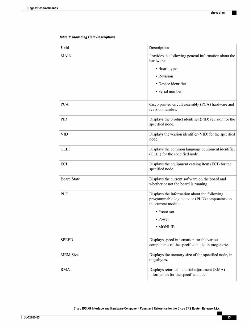
Table 1: show diag Field Descriptions
DescriptionField
Provides the following general information about thehardware:
• Board type
• Revision
• Device identifier
• Serial number
MAIN
Cisco printed circuit assembly (PCA) hardware andrevision number.
PCA
Displays the product identifier (PID) revision for thespecified node.
PID
Displays the version identifier (VID) for the specifiednode.
VID
Displays the common language equipment identifier(CLEI) for the specified node.
CLEI
Displays the equipment catalog item (ECI) for thespecified node.
ECI
Displays the current software on the board andwhether or not the board is running.
Board State
Displays the information about the followingprogrammable logic device (PLD) components onthe current module:
• Processor
• Power
• MONLIB
PLD
Displays speed information for the variouscomponents of the specified node, in megahertz.
SPEED
Displays the memory size of the specified node, inmegabytes.
MEM Size
Displays returned material adjustment (RMA)information for the specified node.
RMA
Cisco IOS XR Interface and Hardware Component Command Reference for the Cisco CRS Router, Release 4.2.x
OL-26065-03 33
Diagnostics Commandsshow diag
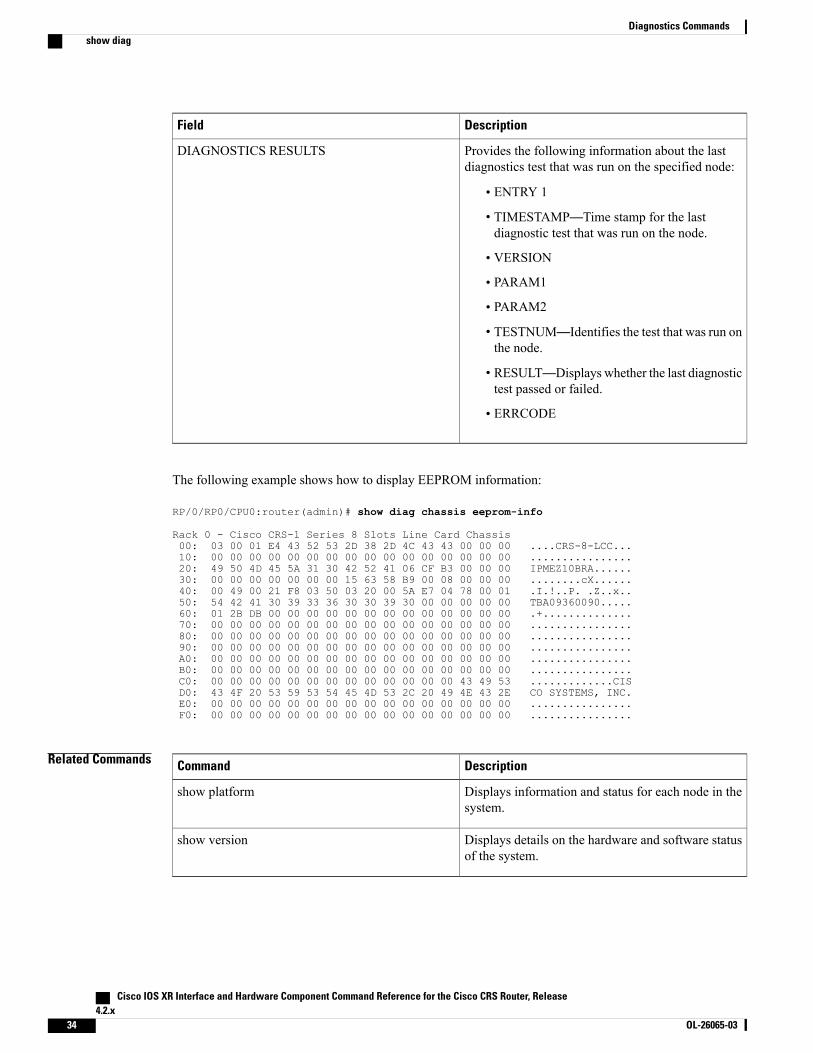
DescriptionField
Provides the following information about the lastdiagnostics test that was run on the specified node:
• ENTRY 1
• TIMESTAMP—Time stamp for the lastdiagnostic test that was run on the node.
• VERSION
• PARAM1
• PARAM2
• TESTNUM—Identifies the test that was run onthe node.
• RESULT—Displays whether the last diagnostictest passed or failed.
• ERRCODE
DIAGNOSTICS RESULTS
The following example shows how to display EEPROM information:
RP/0/RP0/CPU0:router(admin)# show diag chassis eeprom-info
Rack 0 - Cisco CRS-1 Series 8 Slots Line Card Chassis00: 03 00 01 E4 43 52 53 2D 38 2D 4C 43 43 00 00 00 ....CRS-8-LCC...10: 00 00 00 00 00 00 00 00 00 00 00 00 00 00 00 00 ................20: 49 50 4D 45 5A 31 30 42 52 41 06 CF B3 00 00 00 IPMEZ10BRA......30: 00 00 00 00 00 00 00 15 63 58 B9 00 08 00 00 00 ........cX......40: 00 49 00 21 F8 03 50 03 20 00 5A E7 04 78 00 01 .I.!..P. .Z..x..50: 54 42 41 30 39 33 36 30 30 39 30 00 00 00 00 00 TBA09360090.....60: 01 2B DB 00 00 00 00 00 00 00 00 00 00 00 00 00 .+..............70: 00 00 00 00 00 00 00 00 00 00 00 00 00 00 00 00 ................80: 00 00 00 00 00 00 00 00 00 00 00 00 00 00 00 00 ................90: 00 00 00 00 00 00 00 00 00 00 00 00 00 00 00 00 ................A0: 00 00 00 00 00 00 00 00 00 00 00 00 00 00 00 00 ................B0: 00 00 00 00 00 00 00 00 00 00 00 00 00 00 00 00 ................C0: 00 00 00 00 00 00 00 00 00 00 00 00 00 43 49 53 .............CISD0: 43 4F 20 53 59 53 54 45 4D 53 2C 20 49 4E 43 2E CO SYSTEMS, INC.E0: 00 00 00 00 00 00 00 00 00 00 00 00 00 00 00 00 ................F0: 00 00 00 00 00 00 00 00 00 00 00 00 00 00 00 00 ................
Related Commands DescriptionCommand
Displays information and status for each node in thesystem.
show platform
Displays details on the hardware and software statusof the system.
show version
Cisco IOS XR Interface and Hardware Component Command Reference for the Cisco CRS Router, Release4.2.x
34 OL-26065-03
Diagnostics Commandsshow diag
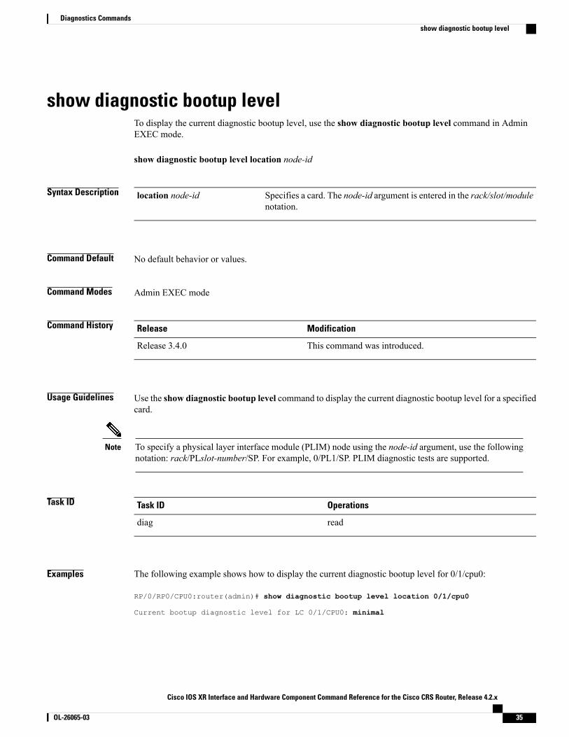
show diagnostic bootup levelTo display the current diagnostic bootup level, use the show diagnostic bootup level command in AdminEXEC mode.
show diagnostic bootup level location node-id
Syntax Description Specifies a card. The node-id argument is entered in the rack/slot/modulenotation.
location node-id
Command Default No default behavior or values.
Command Modes Admin EXEC mode
Command History ModificationRelease
This command was introduced.Release 3.4.0
Usage Guidelines Use the show diagnostic bootup level command to display the current diagnostic bootup level for a specifiedcard.
To specify a physical layer interface module (PLIM) node using the node-id argument, use the followingnotation: rack/PLslot-number/SP. For example, 0/PL1/SP. PLIM diagnostic tests are supported.
Note
Task ID OperationsTask ID
readdiag
Examples The following example shows how to display the current diagnostic bootup level for 0/1/cpu0:
RP/0/RP0/CPU0:router(admin)# show diagnostic bootup level location 0/1/cpu0
Current bootup diagnostic level for LC 0/1/CPU0: minimal
Cisco IOS XR Interface and Hardware Component Command Reference for the Cisco CRS Router, Release 4.2.x
OL-26065-03 35
Diagnostics Commandsshow diagnostic bootup level

show diagnostic contentTo display test information including test ID, test attributes, and supported coverage test levels for each testand for all components, use the show diagnostic content command in Admin EXEC mode.
show diagnostic content location node-id
Syntax Description Displays the diagnostic content for a specified location. The node-id argumentis entered in the rack/slot/module notation.
location node-id
Command Default No default behavior or values
Command Modes Admin EXEC mode
Command History ModificationRelease
This command was introduced.Release 3.3.0
Usage Guidelines Use the show diagnostic content command to display diagnostic test information for a specific location. Thetest information includes the supported tests and attributes.
To specify a physical layer interface module (PLIM) node using the node-id argument, use the followingnotation: rack/PLslot-number/SP. For example, 0/PL1/SP. PLIM diagnostic tests are supported.
Note
For more information about running Cisco IOS XR diagnostics, refer to Cisco IOS XR Diagnostics.
Task ID OperationsTask ID
readdiag
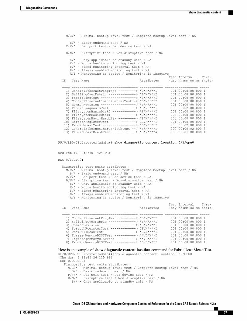
Examples The following example shows how to display the test information for a specified location:
For a route processor:
RP/0/RP0/CPU0:router(admin): show diagnostic contentlocation 0/rp0/cpu0
Diagnostics test suite attributes:
Cisco IOS XR Interface and Hardware Component Command Reference for the Cisco CRS Router, Release4.2.x
36 OL-26065-03
Diagnostics Commandsshow diagnostic content
M/C/* - Minimal bootup level test / Complete bootup level test / NA
B/* - Basic ondemand test / NAP/V/* - Per port test / Per device test / NA
D/N/* - Disruptive test / Non-disruptive test / NA
S/* - Only applicable to standby unit / NAX/* - Not a health monitoring test / NAF/* - Fixed monitoring interval test / NAE/* - Always enabled monitoring test / NAA/I - Monitoring is active / Monitoring is inactive
Test Interval Thre-ID Test Name Attributes (day hh:mm:ss.ms shold)
==== ================================== ============ ================= =====1) ControlEthernetPingTest ---------> *B*N*X**I 001 00:00:00.000 12) SelfPingOverFabric --------------> *B*N*X**I 001 00:00:00.000 13) FabricPingTest ------------------> *B*N*X**I 001 00:00:00.000 14) ControlEthernetInactiveLinkTest -> *B*NS***I 001 00:00:00.000 15) RommonRevision ------------------> *B*N*X**I 001 00:00:00.000 16) FabricDiagnosisTest -------------> *B*NS***I 000 00:02:00.000 17) FilesystemBasicDisk0 ------------> *B*N****I 003 00:00:00.000 18) FilesystemBasicDisk1 ------------> *B*N****I 003 00:00:00.000 19) FilesystemBasicHarddisk ---------> *B*N****I 003 00:00:00.000 110) ScratchRegisterTest -------------> CBVN****I 001 00:00:00.000 111) FabricMcastTest -----------------> *B*NS***I 000 00:02:00.000 112) ControlEthernetIntraSwitchTest --> *B*N****I 000 00:00:02.000 313) FabricUcastMcastTest ------------> *B*N****A 000 00:01:00.000 1
RP/0/RP0/CPU0:router(admin)# show diagnostic content location 0/1/cpu0
Wed Feb 16 09:27:01.424 PST
MSC 0/1/CPU0:
Diagnostics test suite attributes:M/C/* - Minimal bootup level test / Complete bootup level test / NAB/* - Basic ondemand test / NA
P/V/* - Per port test / Per device test / NAD/N/* - Disruptive test / Non-disruptive test / NAS/* - Only applicable to standby unit / NAX/* - Not a health monitoring test / NAF/* - Fixed monitoring interval test / NAE/* - Always enabled monitoring test / NAA/I - Monitoring is active / Monitoring is inactive
Test Interval Thre-ID Test Name Attributes (day hh:mm:ss.ms shold)
==== ================================== ============ ================= =====1) ControlEthernetPingTest ---------> *B*N*X**I 001 00:00:00.000 12) SelfPingOverFabric --------------> *B*N*X**I 001 00:00:00.000 13) RommonRevision ------------------> *B*N*X**I 001 00:00:00.000 14) ScratchRegisterTest -------------> CBVN****I 001 00:00:00.000 15) TcamFullScanTest ----------------> *BVN****I 001 00:00:00.000 16) EgressqMemoryBISTTest -----------> **VD*X**I 001 00:00:00.000 17) IngressqMemoryBISTTest ----------> **VD*X**I 001 00:00:00.000 18) FabricqMemoryBISTTest -----------> **VD*X**I 001 00:00:00.000 1
Here is an example of show diagnostic content location command for FabricUcastMcast Test.RP/0/RP0/CPU0:router(admin)#show diagnostic content location 0/0/CPU0Thu Mar 3 13:45:26.115 PSTDRP 0/0/CPU0:Diagnostics test suite attributes:M/C/* - Minimal bootup level test / Complete bootup level test / NAB/* - Basic ondemand test / NA
P/V/* - Per port test / Per device test / NAD/N/* - Disruptive test / Non-disruptive test / NAS/* - Only applicable to standby unit / NA
Cisco IOS XR Interface and Hardware Component Command Reference for the Cisco CRS Router, Release 4.2.x
OL-26065-03 37
Diagnostics Commandsshow diagnostic content
X/* - Not a health monitoring test / NAF/* - Fixed monitoring interval test / NAE/* - Always enabled monitoring test / NAA/I - Monitoring is active / Monitoring is inactive
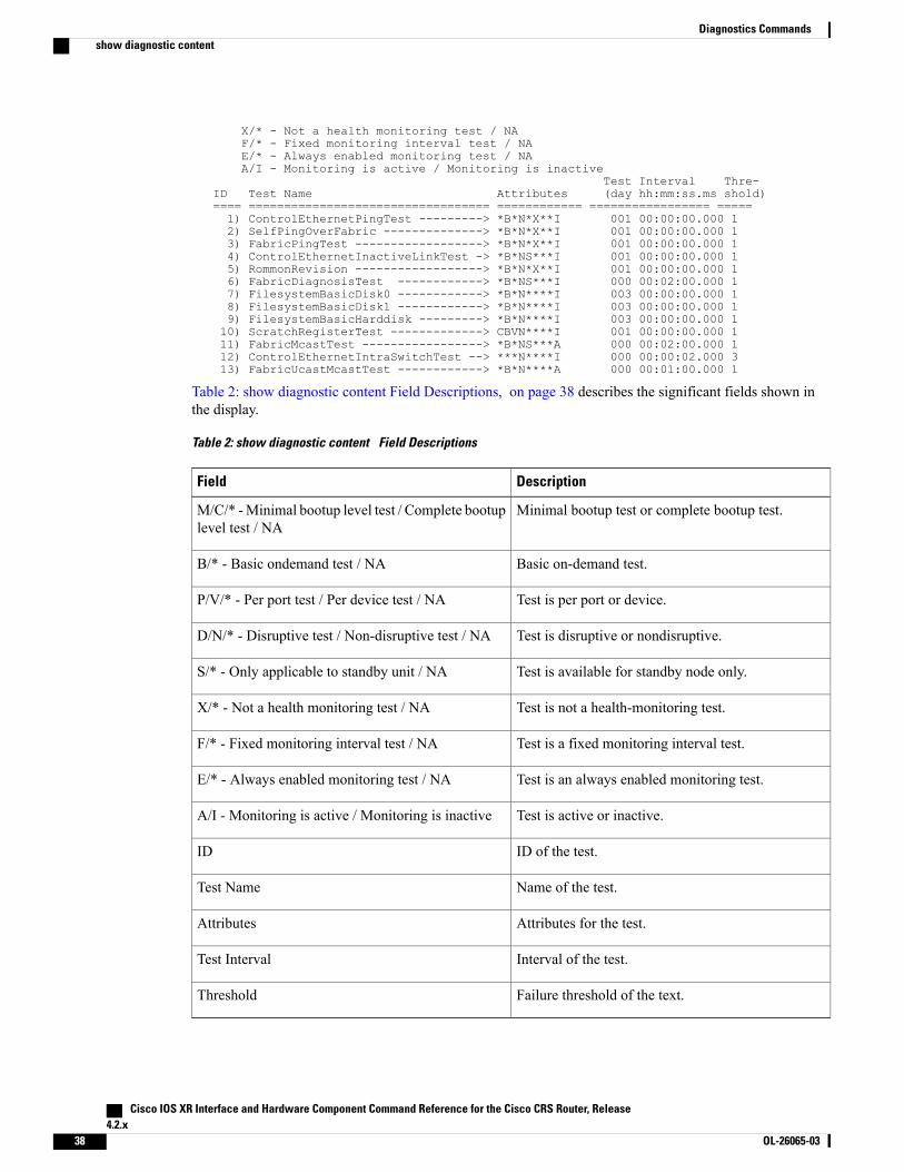
Test Interval Thre-ID Test Name Attributes (day hh:mm:ss.ms shold)==== ================================== ============ ================= =====1) ControlEthernetPingTest ---------> *B*N*X**I 001 00:00:00.000 12) SelfPingOverFabric --------------> *B*N*X**I 001 00:00:00.000 13) FabricPingTest ------------------> *B*N*X**I 001 00:00:00.000 14) ControlEthernetInactiveLinkTest -> *B*NS***I 001 00:00:00.000 15) RommonRevision ------------------> *B*N*X**I 001 00:00:00.000 16) FabricDiagnosisTest ------------> *B*NS***I 000 00:02:00.000 17) FilesystemBasicDisk0 ------------> *B*N****I 003 00:00:00.000 18) FilesystemBasicDisk1 ------------> *B*N****I 003 00:00:00.000 19) FilesystemBasicHarddisk ---------> *B*N****I 003 00:00:00.000 110) ScratchRegisterTest -------------> CBVN****I 001 00:00:00.000 111) FabricMcastTest -----------------> *B*NS***A 000 00:02:00.000 112) ControlEthernetIntraSwitchTest --> ***N****I 000 00:00:02.000 313) FabricUcastMcastTest ------------> *B*N****A 000 00:01:00.000 1
Table 2: show diagnostic content Field Descriptions, on page 38 describes the significant fields shown inthe display.
Table 2: show diagnostic content Field Descriptions
DescriptionField
Minimal bootup test or complete bootup test.M/C/* -Minimal bootup level test / Complete bootuplevel test / NA
Basic on-demand test.B/* - Basic ondemand test / NA
Test is per port or device.P/V/* - Per port test / Per device test / NA
Test is disruptive or nondisruptive.D/N/* - Disruptive test / Non-disruptive test / NA
Test is available for standby node only.S/* - Only applicable to standby unit / NA
Test is not a health-monitoring test.X/* - Not a health monitoring test / NA
Test is a fixed monitoring interval test.F/* - Fixed monitoring interval test / NA
Test is an always enabled monitoring test.E/* - Always enabled monitoring test / NA
Test is active or inactive.A/I - Monitoring is active / Monitoring is inactive
ID of the test.ID
Name of the test.Test Name
Attributes for the test.Attributes
Interval of the test.Test Interval
Failure threshold of the text.Threshold
Cisco IOS XR Interface and Hardware Component Command Reference for the Cisco CRS Router, Release4.2.x
38 OL-26065-03
Diagnostics Commandsshow diagnostic content

Related Commands DescriptionCommand
Loads an offline diagnostic image for integrated fielddiagnostics.
diagnostic load, on page 2
Configures the health-monitoring diagnostic testing for aspecified interval for a specified location.
diagnostic monitor interval, on page 6
Configures a diagnostic schedule.diagnostic schedule, on page 14
Runs a specified diagnostic test.diagnostic start, on page 17
Unloads an offline diagnostic image.diagnostic unload, on page 23
Cisco IOS XR Interface and Hardware Component Command Reference for the Cisco CRS Router, Release 4.2.x
OL-26065-03 39
Diagnostics Commandsshow diagnostic content
show diagnostic ondemand settingsTo display the current on-demand settings, use the show diagnostic ondemand settings command in AdminEXEC mode .
show diagnostic ondemand settings
Syntax Description This command has no keywords or arguments.
Command Default No default behavior or values
Command Modes Admin EXEC mode
Command History ModificationRelease
This command was introduced.Release 3.5.0
Usage Guidelines No specific guidelines impact the use of this command.
Task ID OperationsTask ID
readdiag
Examples The following example shows how to display the on-demand settings:
RP/0/RP0/CPU0:router(admin)# show diagnostic ondemand settings
Test iterations = 45Action on test failure = continue until test failure limit reaches 25
Cisco IOS XR Interface and Hardware Component Command Reference for the Cisco CRS Router, Release4.2.x
40 OL-26065-03
Diagnostics Commandsshow diagnostic ondemand settings
show diagnostic resultTo display diagnostic test results, use the show diagnostic result command in Admin EXEC mode.
show diagnostic result location node-id[test {id| test-name| all}] [detail]
Syntax Description Displays the diagnostic test results for a specified location. The node-id argumentis entered in the rack/slot/module notation.
location node-id
(Optional) Specifies diagnostic test selection. The following test selections areavailable:
• id—Test ID or list of test IDs . Multiple tests can be listed if separated bysemicolons (;) as follows:
◦x;y-z (for example: 1; 3-4 or 1;3;4)
• test-name—Test name.
• all—Specifies all tests.
Use the show diagnostic content command in administration EXEC mode to seea list of test names and their associated IDs.
test {id | test-name | all}
(Optional) Specifies detailed results.detail
Command Default No default behavior or values
Command Modes Admin EXEC mode
Command History ModificationRelease
This command was introduced.Release 3.3.0
Usage Guidelines Use the show diagnostic result command to display diagnostic results for a specific location.
To specify a physical layer interface module (PLIM) node using the node-id argument, use the followingnotation: rack/PLslot-number/SP. For example, 0/PL1/SP. PLIM diagnostic tests are supported.
Note
For more information about running Cisco IOS XR diagnostics, refer to Cisco IOS XR Diagnostics.
Cisco IOS XR Interface and Hardware Component Command Reference for the Cisco CRS Router, Release 4.2.x
OL-26065-03 41
Diagnostics Commandsshow diagnostic result

Task ID OperationsTask ID
readdiag
Examples The following example shows how to display detailed diagnostic test results:
RP/0/RP0/CPU0:router(admin)# show diagnostic result location 0/3/CPU0 test 1 detail
Test results: (. = Pass, F = Fail, U = Untested)___________________________________________________________________________1 ) Control Ethernet Ping Test ------> .Error code ------------------> 0 (DIAG_SUCCESS)Total run count -------------> 1Last test execution time ----> Thu Aug 11 18:13:38.918 2005First test failure time -----> n/aLast test failure time ------> n/aLast test pass time ---------> Thu Aug 11 18:13:38.918 2005Total failure count ---------> 0Consecutive failure count ---> 0
Here is an example of show diagnostic result command to view the results of the FabricUcastMcast Test.RP/1/RP0/CPU0:router(admin)#show diagnostic result location 0/rp1/cpu0 testFabricUcastMcastTest detailFri Mar 4 11:21:01.153 UTCCurrent bootup diagnostic level for RP 0/RP1/CPU0: bypassTest results: (. = Pass, F = Fail, U = Untested)___________________________________________________________________________13 ) FabricUcastMcastTest ------------> .
Error code ------------------> 0 (DIAG_SUCCESS)Total run count -------------> 17Last test execution time ----> Fri Mar 4 11:20:54 2011First test failure time -----> Fri Mar 4 11:19:47 2011Last test failure time ------> Fri Mar 4 11:19:47 2011Last test pass time ---------> Fri Mar 4 11:20:54 2011Total failure count ---------> 1Consecutive failure count ---> 0
Unicast Resultsdest: (all nodes) session_id: 48ret_code: 0 (No error)rx_ret_code: 0 (No error)tx_ret_code: 0 (No error)min_rtt_ms: 2 max_rtt_ms: 63ping_mode_mask: 0x00000099 fplane_bitmap: 0x000000ffinter_packet_delay: 0 max_timeout_ms: 1500late_timeout_ms: 1500 priority: 0flags: 0x00000000 pkt_cnt: 10pkt_size: 1000 num_nodes: 15tx_start_ts: 11:20:54.488 UTC Fri Mar 04 2011modes: 0 - LP/fabricq0, 3 - LP/fabricq1, 4 - HP/fabricq0, 7 - HP/fabricq1
node[mode] req'ed rx_good tx_good tx_unrea tx_err rx_unexp rx_corr============== ======== ======== ======== ======== ======== ======== ========
0/0/CPU0[0] 10 10 10 0 0 0 00/0/CPU0[3] 10 10 10 0 0 0 00/0/CPU0[4] 10 10 10 0 0 0 00/0/CPU0[7] 10 10 10 0 0 0 00/4/CPU0[0] 10 10 10 0 0 0 00/4/CPU0[3] 10 10 10 0 0 0 00/4/CPU0[4] 10 10 10 0 0 0 00/4/CPU0[7] 10 10 10 0 0 0 00/5/CPU0[0] 10 10 10 0 0 0 00/5/CPU0[3] 10 10 10 0 0 0 00/5/CPU0[4] 10 10 10 0 0 0 00/5/CPU0[7] 10 10 10 0 0 0 00/6/CPU0[0] 10 10 10 0 0 0 0
Cisco IOS XR Interface and Hardware Component Command Reference for the Cisco CRS Router, Release4.2.x
42 OL-26065-03
Diagnostics Commandsshow diagnostic result

0/6/CPU0[3] 10 10 10 0 0 0 00/6/CPU0[4] 10 10 10 0 0 0 00/6/CPU0[7] 10 10 10 0 0 0 00/8/CPU0[0] 10 10 10 0 0 0 00/8/CPU0[4] 10 10 10 0 0 0 0
0/RP0/CPU0[0] 10 10 10 0 0 0 00/RP0/CPU0[4] 10 10 10 0 0 0 00/RP1/CPU0[0] 10 10 10 0 0 0 00/RP1/CPU0[4] 10 10 10 0 0 0 01/3/CPU0[0] 10 10 10 0 0 0 01/3/CPU0[3] 10 10 10 0 0 0 01/3/CPU0[4] 10 10 10 0 0 0 01/3/CPU0[7] 10 10 10 0 0 0 01/4/CPU0[0] 10 10 10 0 0 0 01/4/CPU0[3] 10 10 10 0 0 0 01/4/CPU0[4] 10 10 10 0 0 0 01/4/CPU0[7] 10 10 10 0 0 0 01/7/CPU0[0] 10 10 10 0 0 0 01/7/CPU0[4] 10 10 10 0 0 0 01/9/CPU0[0] 10 10 10 0 0 0 01/9/CPU0[3] 10 10 10 0 0 0 01/9/CPU0[4] 10 10 10 0 0 0 01/9/CPU0[7] 10 10 10 0 0 0 01/14/CPU0[0] 10 10 10 0 0 0 01/14/CPU0[3] 10 10 10 0 0 0 01/14/CPU0[4] 10 10 10 0 0 0 01/14/CPU0[7] 10 10 10 0 0 0 01/15/CPU0[0] 10 10 10 0 0 0 01/15/CPU0[4] 10 10 10 0 0 0 01/RP0/CPU0[0] 10 10 10 0 0 0 01/RP0/CPU0[4] 10 10 10 0 0 0 01/RP1/CPU0[0] 10 10 10 0 0 0 01/RP1/CPU0[4] 10 10 10 0 0 0 0============== ======== ======== ======== ======== ======== ======== ========Global 460 460 460 0 0 0 0
Unicast Results (Last Failure)dest: (all nodes) session_id: 30ret_code: 606182912 ('FAB_SVR' detected the 'informational' condition
'Timed outwaiting for all ping replies.')
rx_ret_code: 0 (No error)tx_ret_code: 0 (No error)min_rtt_ms: 2 max_rtt_ms: 61ping_mode_mask: 0x00000099 fplane_bitmap: 0x000000ffinter_packet_delay: 0 max_timeout_ms: 1500late_timeout_ms: 1500 priority: 0flags: 0x00000000 pkt_cnt: 10pkt_size: 1000 num_nodes: 15tx_start_ts: 11:19:47.167 UTC Fri Mar 04 2011modes: 0 - LP/fabricq0, 3 - LP/fabricq1, 4 - HP/fabricq0, 7 - HP/fabricq1
node[mode] req'ed rx_good tx_good tx_unrea tx_err rx_unexp rx_corr============== ======== ======== ======== ======== ======== ======== ========
0/0/CPU0[0] 10 0 10 0 0 0 00/0/CPU0[3] 10 0 10 0 0 0 00/0/CPU0[4] 10 0 10 0 0 0 00/0/CPU0[7] 10 0 10 0 0 0 00/4/CPU0[0] 10 10 10 0 0 0 00/4/CPU0[3] 10 10 10 0 0 0 00/4/CPU0[4] 10 10 10 0 0 0 00/4/CPU0[7] 10 10 10 0 0 0 00/5/CPU0[0] 10 10 10 0 0 0 00/5/CPU0[3] 10 10 10 0 0 0 00/5/CPU0[4] 10 10 10 0 0 0 00/5/CPU0[7] 10 10 10 0 0 0 00/6/CPU0[0] 10 10 10 0 0 0 00/6/CPU0[3] 10 10 10 0 0 0 00/6/CPU0[4] 10 10 10 0 0 0 00/6/CPU0[7] 10 10 10 0 0 0 00/8/CPU0[0] 10 10 10 0 0 0 00/8/CPU0[4] 10 10 10 0 0 0 0
0/RP0/CPU0[0] 10 10 10 0 0 0 00/RP0/CPU0[4] 10 10 10 0 0 0 0
Cisco IOS XR Interface and Hardware Component Command Reference for the Cisco CRS Router, Release 4.2.x
OL-26065-03 43
Diagnostics Commandsshow diagnostic result

0/RP1/CPU0[0] 10 10 10 0 0 0 00/RP1/CPU0[4] 10 10 10 0 0 0 01/3/CPU0[0] 10 10 10 0 0 0 01/3/CPU0[3] 10 10 10 0 0 0 01/3/CPU0[4] 10 10 10 0 0 0 01/3/CPU0[7] 10 10 10 0 0 0 01/4/CPU0[0] 10 10 10 0 0 0 01/4/CPU0[3] 10 10 10 0 0 0 01/4/CPU0[4] 10 10 10 0 0 0 01/4/CPU0[7] 10 10 10 0 0 0 01/7/CPU0[0] 10 10 10 0 0 0 01/7/CPU0[4] 10 10 10 0 0 0 01/9/CPU0[0] 10 10 10 0 0 0 01/9/CPU0[3] 10 10 10 0 0 0 01/9/CPU0[4] 10 10 10 0 0 0 01/9/CPU0[7] 10 10 10 0 0 0 01/14/CPU0[0] 10 10 10 0 0 0 01/14/CPU0[3] 10 10 10 0 0 0 01/14/CPU0[4] 10 10 10 0 0 0 01/14/CPU0[7] 10 10 10 0 0 0 01/15/CPU0[0] 10 10 10 0 0 0 01/15/CPU0[4] 10 10 10 0 0 0 01/RP0/CPU0[0] 10 10 10 0 0 0 01/RP0/CPU0[4] 10 10 10 0 0 0 01/RP1/CPU0[0] 10 10 10 0 0 0 01/RP1/CPU0[4] 10 10 10 0 0 0 0============== ======== ======== ======== ======== ======== ======== ========Global 460 420 460 0 0 0 0
Multicast Resultsdest: FGID 1023 session_id: 49ret_code: 0 (No error)rx_ret_code: 0 (No error)tx_ret_code: 0 (No error)min_rtt_ms: 13 max_rtt_ms: 58ping_mode_mask: 0x00000011 fplane_bitmap: 0x000000ffinter_packet_delay: 0 max_timeout_ms: 1500late_timeout_ms: 1500 priority: 0flags: 0x00000000 pkt_cnt: 10pkt_size: 1000 num_nodes: 15tx_start_ts: 11:20:54.492 UTC Fri Mar 04 2011modes: 0 - LP/fabricq0, 4 - HP/fabricq0
node[mode] req'ed rx_good tx_good tx_unrea tx_err rx_unexp rx_corr============== ======== ======== ======== ======== ======== ======== ========
0/0/CPU0[0] 10 10 10 0 0 0 00/0/CPU0[4] 10 10 10 0 0 0 00/4/CPU0[0] 10 10 10 0 0 0 00/4/CPU0[4] 10 10 10 0 0 0 00/5/CPU0[0] 10 10 10 0 0 0 00/5/CPU0[4] 10 10 10 0 0 0 00/6/CPU0[0] 10 10 10 0 0 0 00/6/CPU0[4] 10 10 10 0 0 0 00/8/CPU0[0] 10 10 10 0 0 0 00/8/CPU0[4] 10 10 10 0 0 0 0
0/RP0/CPU0[0] 10 10 10 0 0 0 00/RP0/CPU0[4] 10 10 10 0 0 0 00/RP1/CPU0[0] 10 10 10 0 0 0 00/RP1/CPU0[4] 10 10 10 0 0 0 01/3/CPU0[0] 10 10 10 0 0 0 01/3/CPU0[4] 10 10 10 0 0 0 01/4/CPU0[0] 10 10 10 0 0 0 01/4/CPU0[4] 10 10 10 0 0 0 01/7/CPU0[0] 10 10 10 0 0 0 01/7/CPU0[4] 10 10 10 0 0 0 01/9/CPU0[0] 10 10 10 0 0 0 01/9/CPU0[4] 10 10 10 0 0 0 01/14/CPU0[0] 10 10 10 0 0 0 01/14/CPU0[4] 10 10 10 0 0 0 01/15/CPU0[0] 10 10 10 0 0 0 01/15/CPU0[4] 10 10 10 0 0 0 01/RP0/CPU0[0] 10 10 10 0 0 0 01/RP0/CPU0[4] 10 10 10 0 0 0 01/RP1/CPU0[0] 10 10 10 0 0 0 01/RP1/CPU0[4] 10 10 10 0 0 0 0
Cisco IOS XR Interface and Hardware Component Command Reference for the Cisco CRS Router, Release4.2.x
44 OL-26065-03
Diagnostics Commandsshow diagnostic result
============== ======== ======== ======== ======== ======== ======== ========Global 300 300 300 0 0 0 0
Multicast Results (Last Failure)dest: FGID 1023 session_id: 31ret_code: 0 (No error)rx_ret_code: 0 (No error)tx_ret_code: 0 (No error)min_rtt_ms: 14 max_rtt_ms: 58ping_mode_mask: 0x00000011 fplane_bitmap: 0x000000ffinter_packet_delay: 0 max_timeout_ms: 1500late_timeout_ms: 1500 priority: 0flags: 0x00000000 pkt_cnt: 10pkt_size: 1000 num_nodes: 15tx_start_ts: 11:19:47.171 UTC Fri Mar 04 2011modes: 0 - LP/fabricq0, 4 - HP/fabricq0
node[mode] req'ed rx_good tx_good tx_unrea tx_err rx_unexp rx_corr============== ======== ======== ======== ======== ======== ======== ========
0/0/CPU0[0] 10 10 10 0 0 0 00/0/CPU0[4] 10 10 10 0 0 0 00/4/CPU0[0] 10 10 10 0 0 0 00/4/CPU0[4] 10 10 10 0 0 0 00/5/CPU0[0] 10 10 10 0 0 0 00/5/CPU0[4] 10 10 10 0 0 0 00/6/CPU0[0] 10 10 10 0 0 0 00/6/CPU0[4] 10 10 10 0 0 0 00/8/CPU0[0] 10 10 10 0 0 0 00/8/CPU0[4] 10 10 10 0 0 0 0
0/RP0/CPU0[0] 10 10 10 0 0 0 00/RP0/CPU0[4] 10 10 10 0 0 0 00/RP1/CPU0[0] 10 10 10 0 0 0 00/RP1/CPU0[4] 10 10 10 0 0 0 01/3/CPU0[0] 10 10 10 0 0 0 01/3/CPU0[4] 10 10 10 0 0 0 01/4/CPU0[0] 10 10 10 0 0 0 01/4/CPU0[4] 10 10 10 0 0 0 01/7/CPU0[0] 10 10 10 0 0 0 01/7/CPU0[4] 10 10 10 0 0 0 01/9/CPU0[0] 10 10 10 0 0 0 01/9/CPU0[4] 10 10 10 0 0 0 01/14/CPU0[0] 10 10 10 0 0 0 01/14/CPU0[4] 10 10 10 0 0 0 01/15/CPU0[0] 10 10 10 0 0 0 01/15/CPU0[4] 10 10 10 0 0 0 01/RP0/CPU0[0] 10 10 10 0 0 0 01/RP0/CPU0[4] 10 10 10 0 0 0 01/RP1/CPU0[0] 10 10 10 0 0 0 01/RP1/CPU0[4] 10 10 10 0 0 0 0============== ======== ======== ======== ======== ======== ======== ========Global 300 300 300 0 0 0 0
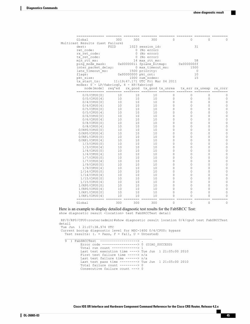
Here is an example to display detailed diagnostic test results for the FabSRCC Test:show diagnostic result <location> test FabSRCCTest detail
RP/0/RP0/CPU0:router(admin)#show diagnostic result location 0/4/cpu0 test FabSRCCTestdetailTue Jun 1 21:07:38.974 UTCCurrent bootup diagnostic level for MSC-140G 0/4/CPU0: bypassTest results: (. = Pass, F = Fail, U = Untested)___________________________________________________________________________9 ) FabSRCCTest -------------------> .
Error code ------------------> 0 (DIAG_SUCCESS)Total run count -------------> 1Last test execution time ----> Tue Jun 1 21:05:00 2010First test failure time -----> n/aLast test failure time ------> n/aLast test pass time ---------> Tue Jun 1 21:05:00 2010Total failure count ---------> 0Consecutive failure count ---> 0
Cisco IOS XR Interface and Hardware Component Command Reference for the Cisco CRS Router, Release 4.2.x
OL-26065-03 45
Diagnostics Commandsshow diagnostic result
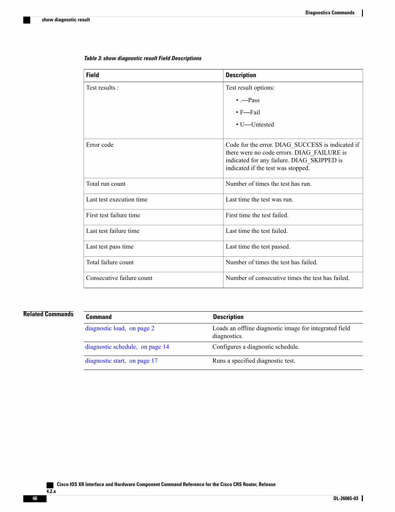
Table 3: show diagnostic result Field Descriptions
DescriptionField
Test result options:
• .—Pass
• F—Fail
• U—Untested
Test results :
Code for the error. DIAG_SUCCESS is indicated ifthere were no code errors. DIAG_FAILURE isindicated for any failure. DIAG_SKIPPED isindicated if the test was stopped.
Error code
Number of times the test has run.Total run count
Last time the test was run.Last test execution time
First time the test failed.First test failure time
Last time the test failed.Last test failure time
Last time the test passed.Last test pass time
Number of times the test has failed.Total failure count
Number of consecutive times the test has failed.Consecutive failure count
Related Commands DescriptionCommand
Loads an offline diagnostic image for integrated fielddiagnostics.
diagnostic load, on page 2
Configures a diagnostic schedule.diagnostic schedule, on page 14
Runs a specified diagnostic test.diagnostic start, on page 17
Cisco IOS XR Interface and Hardware Component Command Reference for the Cisco CRS Router, Release4.2.x
46 OL-26065-03
Diagnostics Commandsshow diagnostic result
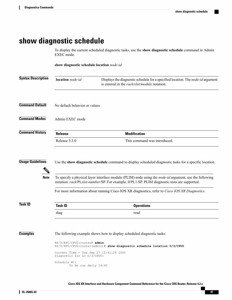
show diagnostic scheduleTo display the current scheduled diagnostic tasks, use the show diagnostic schedule command in AdminEXEC mode.
show diagnostic schedule location node-id
Syntax Description Displays the diagnostic schedule for a specified location. The node-id argumentis entered in the rack/slot/module notation.
location node-id
Command Default No default behavior or values
Command Modes Admin EXEC mode
Command History ModificationRelease
This command was introduced.Release 3.3.0
Usage Guidelines Use the show diagnostic schedule command to display scheduled diagnostic tasks for a specific location.
To specify a physical layer interface module (PLIM) node using the node-id argument, use the followingnotation: rack/PLslot-number/SP. For example, 0/PL1/SP. PLIM diagnostic tests are supported.
Note
For more information about running Cisco IOS XR diagnostics, refer to Cisco IOS XR Diagnostics.
Task ID OperationsTask ID
readdiag
Examples The following example shows how to display scheduled diagnostic tasks:
RP/0/RP0/CPU0:router# adminRP/0/RP0/CPU0:router(admin)# show diagnostic schedule location 0/3/CPU0
Current Time = Tue Sep 27 12:41:24 2005Diagnostic for LC 0/3/CPU0:
Schedule #1:To be run daily 14:40
Cisco IOS XR Interface and Hardware Component Command Reference for the Cisco CRS Router, Release 4.2.x
OL-26065-03 47
Diagnostics Commandsshow diagnostic schedule
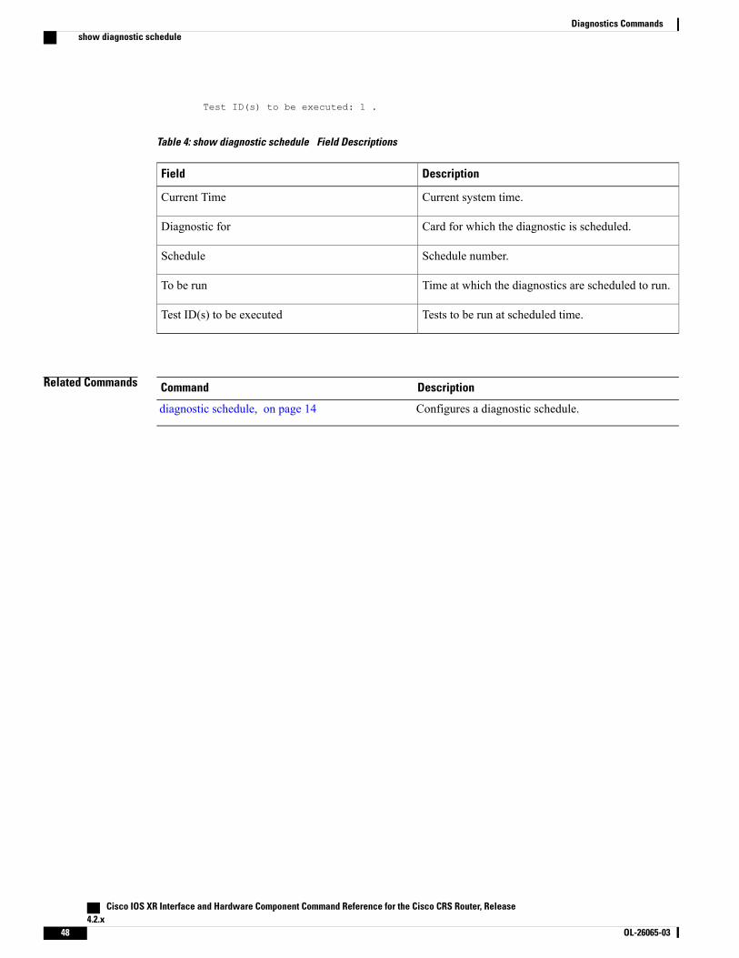
Test ID(s) to be executed: 1 .
Table 4: show diagnostic schedule Field Descriptions
DescriptionField
Current system time.Current Time
Card for which the diagnostic is scheduled.Diagnostic for
Schedule number.Schedule
Time at which the diagnostics are scheduled to run.To be run
Tests to be run at scheduled time.Test ID(s) to be executed
Related Commands DescriptionCommand
Configures a diagnostic schedule.diagnostic schedule, on page 14
Cisco IOS XR Interface and Hardware Component Command Reference for the Cisco CRS Router, Release4.2.x
48 OL-26065-03
Diagnostics Commandsshow diagnostic schedule
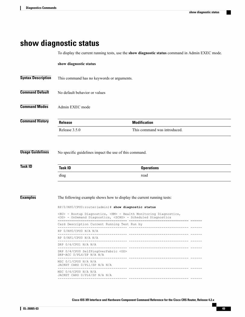
show diagnostic statusTo display the current running tests, use the show diagnostic status command in Admin EXEC mode.
show diagnostic status
Syntax Description This command has no keywords or arguments.
Command Default No default behavior or values
Command Modes Admin EXEC mode
Command History ModificationRelease
This command was introduced.Release 3.5.0
Usage Guidelines No specific guidelines impact the use of this command.
Task ID OperationsTask ID
readdiag
Examples The following example shows how to display the current running tests:
RP/0/RP0/CPU0:router(admin)# show diagnostic status
<BU> - Bootup Diagnostics, <HM> - Health Monitoring Diagnostics,<OD> - OnDemand Diagnostics, <SCHD> - Scheduled Diagnostics==================================== =============================== ======Card Description Current Running Test Run by------------------------------------ ------------------------------- ------RP 0/RP0/CPU0 N/A N/A------------------------------------ ------------------------------- ------RP 0/RP1/CPU0 N/A N/A------------------------------------ ------------------------------- ------DRP 0/4/CPU1 N/A N/A------------------------------------ ------------------------------- ------DRP 0/4/CPU0 SelfPingOverFabric <OD>DRP-ACC 0/PL4/SP N/A N/A------------------------------------ ------------------------------- ------MSC 0/1/CPU0 N/A N/AJACKET CARD 0/PL1/SP N/A N/A------------------------------------ ------------------------------- ------MSC 0/6/CPU0 N/A N/AJACKET CARD 0/PL6/SP N/A N/A------------------------------------ ------------------------------- ------
Cisco IOS XR Interface and Hardware Component Command Reference for the Cisco CRS Router, Release 4.2.x
OL-26065-03 49
Diagnostics Commandsshow diagnostic status
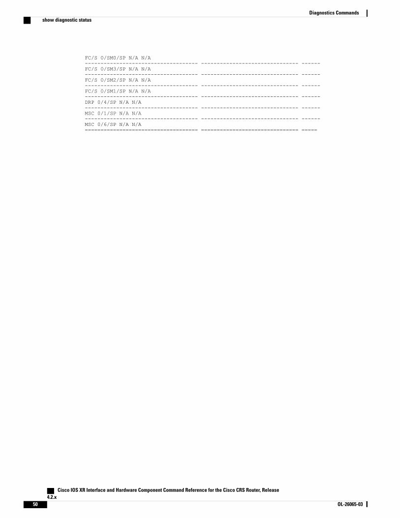
FC/S 0/SM0/SP N/A N/A------------------------------------ ------------------------------- ------FC/S 0/SM3/SP N/A N/A------------------------------------ ------------------------------- ------FC/S 0/SM2/SP N/A N/A------------------------------------ ------------------------------- ------FC/S 0/SM1/SP N/A N/A------------------------------------ ------------------------------- ------DRP 0/4/SP N/A N/A------------------------------------ ------------------------------- ------MSC 0/1/SP N/A N/A------------------------------------ ------------------------------- ------MSC 0/6/SP N/A N/A==================================== =============================== =====
Cisco IOS XR Interface and Hardware Component Command Reference for the Cisco CRS Router, Release4.2.x
50 OL-26065-03
Diagnostics Commandsshow diagnostic status

show run diagnostic monitorTo display the card type of a line card or a Shared Port Adapter (SPA), use the show run diagnostic monitorcommand in the Admin Configuration mode.
show run diagnostic monitor
Syntax Description This command has no keywords or arguments.
Command Default No default behavior or values
Command Modes Admin Configuration mode
Command History ModificationRelease
This command was introduced.Release 3.8.0
Usage Guidelines You need to be aware of the card type when you configure a slot or swap a card, and the configuration mustre-apply. If the card type is different, the configuration does not re-apply. You can display the card type usingthe show run diagnostic monitor command in the administration configuration mode.
Task ID OperationsTask ID
read, writediag
ExamplesRP/0/RP0/CPU0:router#adminRP/0/RP0/CPU0:router(admin)# configRP/0/RP0/CPU0:router(admin-config)# diagnostic monitor location 0/RP1/CPU0 testFabricDiagnosisTestRP/0/RP0/CPU0:router(admin-config)# commitRP/0/RP0/CPU0:router(admin-config)# endRP/0/RP0/CPU0:router(admin)# show run diagnostic monitor
diagnostic monitor location 0/RP1/CPU0 test FabricDiagnosisTest card-type 100006
Cisco IOS XR Interface and Hardware Component Command Reference for the Cisco CRS Router, Release 4.2.x
OL-26065-03 51
Diagnostics Commandsshow run diagnostic monitor

Cisco IOS XR Interface and Hardware Component Command Reference for the Cisco CRS Router, Release4.2.x
52 OL-26065-03
Diagnostics Commandsshow run diagnostic monitor