Embed Size (px)
Citation preview
C
DUJ
Mtrilpettdadnuauoo
I
Pgn[rscfqitpcscsicudtwt
p
6
linical Reviews: Current Concepts
iagnostic and Interventional Musculoskeletalltrasound: Part 1. Fundamentals
ay Smith, MD, Jonathan T. Finnoff, DO
JRC5eD
JRCD
Sa
usculoskeletal ultrasound involves the use of high-frequency sound waves to image softissues and bony structures in the body for the purposes of diagnosing pathology or guidingeal-time interventional procedures. Recently, an increasing number of physicians haventegrated musculoskeletal ultrasound into their practices to facilitate patient care. Techno-ogical advancements, improved portability, and reduced costs continue to drive theroliferation of ultrasound in clinical medicine. This increased interest creates a need forducation pertaining to all aspects of musculoskeletal ultrasound. The primary purpose ofhis article is to review diagnostic ultrasound technology and its potential clinical applica-ions in the evaluation and treatment of patients with neurologic and musculoskeletalisorders. After reviewing this article, physicians should be able to (1) list the advantagesnd disadvantages of ultrasound compared with other available imaging modalities, (2)escribe how ultrasound machines produce images using sound waves, (3) discuss the stepsecessary to acquire and optimize an ultrasound image, (4) understand the differentltrasound appearances of tendons, nerves, muscles, ligaments, blood vessels, and bones,nd (5) identify multiple applications for diagnostic and interventional musculoskeletalltrasound in musculoskeletal practice. Part 1 of this 2-part article reviews the fundamentalsf clinical ultrasonographic imaging, including relevant physics, equipment, training, imageptimization, and scanning principles for diagnostic and interventional purposes.
NTRODUCTION
hysiatrists have been pioneers in the field of ultrasound for over 5 decades. In 1951, aroup of 24 physiatrists recognized the emerging clinical importance of ultrasound tech-ology and eventually founded the American Institute for Ultrasound in Medicine (AIUM)1]. During the following years, physiatrists continued to lead the medical community withespect to therapeutic ultrasound [2,3]. However, diagnostic applications in the musculo-keletal system remained limited due to poor resolution and lack of real-time imagingapabilities [1]. By the 1980s, real-time ultrasonographic imaging became widely available,acilitating a more efficient, interactive, and clinically useful examination [1]. High-fre-uency transducers were introduced in the late 1980s, providing the detailed anatomic
maging necessary to effectively evaluate the musculoskeletal system [1]. Following theseechnological advancements, radiologists and sonographers began to explore the diagnosticotential of musculoskeletal ultrasound [4,5]. Continued improvements in resolutionoupled with equipment price reductions subsequently brought musculoskeletal ultra-ound into the practices of physiatrists, rheumatologists, orthopedic surgeons, and otherlinicians, who began to directly apply the technology to diagnose and manage musculo-keletal disorders. Physicians in general, and physiatrists in particular, have been prescrib-ng therapeutic ultrasound for over 50 years and have now revisited ultrasound within theontext of its diagnostic capabilities. Today, many practitioners have already integratedltrasound into their practices to diagnose tendon, nerve, muscle, ligament, and jointisorders, as well as guide therapeutic procedures. As musculoskeletal ultrasound continueso proliferate, it is imperative that any interested physician acquire a basic understanding ofhat diagnostic and interventional musculoskeletal ultrasound is and how it may apply to
he care of their patients.This 2-part article [6] will familiarize physicians with ultrasound technology and its
otential clinical applications in the evaluation and treatment of patients with neurologicalDC
PM&R © 2009 by the American Academy of P1934-1482/09/$36.00
Printed in U.S.A.4
.S. Department of Physical Medicine andehabilitation, College of Medicine, Mayolinic, 200 First St SW, Rochester, MN5905. Address correspondence to: J.S.;-mail: [email protected]: nothing to disclose
.T.F. Department of Physical Medicine andehabilitation, College of Medicine, Mayolinic, Rochester, MNisclosure: nothing to disclose
ubmitted for publication July 10, 2008;ccepted September 30.
isclosure Key can be found on the Table ofontents and at www.pmrjournal.org
hysical Medicine and RehabilitationVol. 1, 64-75, January 2009
DOI: 10.1016/j.pmrj.2008.09.001

apdipnunittgtd
W
MqbpMtmnHaaqsmat
sri
nacitSppdtastitmrarcepdcaSvsr
ltpocfippdsapliidamsf
T
HAFCM
AEPRLN
T
●
●
●
65PM&R Vol. 1, Iss. 1, 2009
nd musculoskeletal disorders. After reviewing this article,hysicians should be able to: (1) list the advantages andisadvantages of ultrasound compared to other available
maging modalities, (2) describe how ultrasound machinesroduce images using sound waves, (3) discuss the stepsecessary to acquire and optimize an ultrasound image, (4)nderstand the different ultrasound appearances of tendons,erves, muscles, ligaments, blood vessels, and bones, and (5)
dentify multiple applications for diagnostic and interven-ional musculoskeletal ultrasound in musculoskeletal prac-ice. Part 1 will review the fundamentals of clinical ultrasono-raphic imaging, including relevant physics, equipment,raining, image optimization. and scanning principles foriagnostic and interventional purposes .
HAT IS MUSCULOSKELETAL ULTRASOUND?
usculoskeletal ultrasound involves the use of high-fre-uency sound waves (3-17 MHz) to image soft tissues andony structures in the body for the purposes of diagnosingathology or guiding real-time interventional procedures.odern-day ultrasound machines provide exquisitely de-
ailed images of the musculoskeletal system, delivering sub-illimeter resolution that is superior to comparative mag-etic resonance imaging (MRI) studies in most cases [7].igh-resolution scanning produces detailed anatomic im-
ges of tendons, nerves, ligaments, joint capsules, muscles,nd other relevant structures throughout the body. Conse-uently, physicians can use ultrasound to diagnose tendino-is, partial- or full-thickness tendon tears, nerve entrap-ents, muscle strains, ligament sprains, and joint effusions,
s well as guide real-time interventional procedures to treathese pathologies as clinically indicated.
In addition to higher resolution, musculoskeletal ultra-ound provides several distinct advantages relative to radiog-aphy, computed tomography (CT), and MRI when perform-ng focused examinations of the musculoskeletal or
able 1. Advantages of musculoskeletal ultrasound
igh-resolution soft tissue imagingbility to image in real-timeacilitates dynamic examination of anatomic structuresan interact with the patient while imaginginimally affected by metal artifact (ie, implants
and hardware)bility to guide procedures (eg, aspirations, injections)nables rapid contralateral limb examination for comparisonortableelatively inexpensiveacks radiationo known contraindications
able 2. Disadvantages of musculoskeletal ultrasound
Technical
Limited field of viewIncomplete evaluation of bones and joints
● Opera● Lack o
Limited penetration ● Lack of certifi
eurological system (Table 1). Most important, ultrasound ishands-on, dynamic, and interactive examination [8]. The
linician uses the information gained from the history, phys-cal examination, and available diagnostic testing to definehe clinical question and identify the region for examination.tatic ultrasonographic imaging is supplemented with sono-alpation—precisely localizing the structures over which theatient is maximally tender by palpating under the trans-ucer and eliciting patient feedback. With the assistance ofhe patient, joint and tendon motion, muscle contraction,nd provocative testing may all be performed during ultra-onographic visualization to reveal clinically important pa-hologies, such as dislocating ulnar nerves, snappingliopsoas tendons, or dislocating biceps tendons [9-11]. Ul-rasound is generally unaffected by metallic artifacts (eg,etatarsal plate in the foot, suture anchors) and delivers no
adiation to the patient or the user, an important consider-tion when evaluating females of child-bearing age. Unlikeadiographs, CT, and MRI, ultrasound can be readily used toomplete a comparative examination of the contralateralxtremity when clinically indicated. Finally, ultrasound canrovide precise, real-time guidance for interventional proce-ures. Compared with radiographs and CT scans, ultrasoundan demonstrate soft tissues with great detail, enabling safend accurate needle guidance for interventional procedures.imilar to ultrasound, MRI provides excellent soft tissueisualization, but the requirement for nonferromagnetic in-trumentation coupled equipment size and expense cur-ently limit MRI use for real-time interventional procedures.
Physicians should recognize several clinically relevantimitations of musculoskeletal ultrasound (Table 2). Perhapshe most important limitations pertain to field of view andenetration. Ultrasound provides a very high quality picturef a relatively small area. Clinicians should use ultrasound toonfirm or characterize pathological changes within a de-ned body region. A patient presenting with “diffuse ankleain” is not optimal for ultrasound examination; such aatient would be better served with CT, MRI, or bone scan,epending on the clinical circumstances. Conversely, ultra-ound could be considered the initial test of choice to evalu-te a patient presenting with posteromedial ankle pain sus-ected of having posterior tibial tendinopathy. As discussed
ater, ultrasound’s limited resolution at greater depths andnability to penetrate bone limit its ability to adequatelymage deep body regions, morbidly obese patients, areaseep to bones, and central intra-articular regions [7]. Finally,s an interactive and technologically intensive examination,usculoskeletal ultrasound is also limited by both the ultra-
ound machine and the skill of the examiner using it. Theseactors will be discussed subsequently.
Examiner Equipment
endentational infrastructure
● Cost● Variable quality
tor depf educ
cation or accreditation process
MT
Mdmawtmtps
U
Aa(csadgiestgcc
adc
siuooptrtterdcTrtgrdu
Fsfttlsftt
Fueitt�ds
66 Smith and Finnoff MUSCULOSKELETAL ULTRASOUND: PART 1.
USCULOSKELETAL ULTRASOUND:HE PREREQUISITES
usculoskeletal ultrasound is perhaps the most operator-ependent imaging modality currently available. The pri-ary reason for this is the need to physically acquire an
cceptable image, using appropriately adjusted equipment,ith specific attention to transducer positioning, all within
he context of an in-depth understanding of neurological andusculoskeletal anatomy. To successfully integrate diagnos-
ic or interventional musculoskeletal ultrasound into clinicalractice, the practitioner must therefore acquire the neces-ary equipment, education, and scanning skills.
ltrasound Equipment
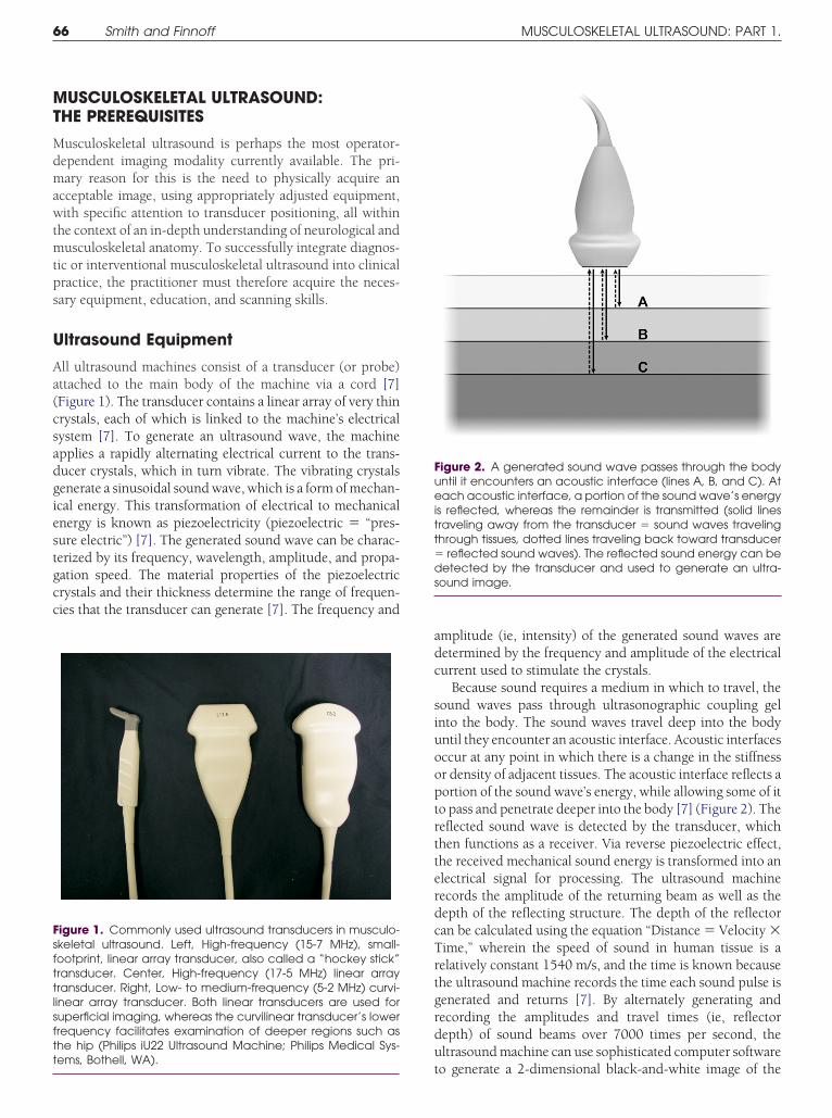
ll ultrasound machines consist of a transducer (or probe)ttached to the main body of the machine via a cord [7]Figure 1). The transducer contains a linear array of very thinrystals, each of which is linked to the machine’s electricalystem [7]. To generate an ultrasound wave, the machinepplies a rapidly alternating electrical current to the trans-ucer crystals, which in turn vibrate. The vibrating crystalsenerate a sinusoidal sound wave, which is a form of mechan-cal energy. This transformation of electrical to mechanicalnergy is known as piezoelectricity (piezoelectric � “pres-ure electric”) [7]. The generated sound wave can be charac-erized by its frequency, wavelength, amplitude, and propa-ation speed. The material properties of the piezoelectricrystals and their thickness determine the range of frequen-ies that the transducer can generate [7]. The frequency and
igure 1. Commonly used ultrasound transducers in musculo-keletal ultrasound. Left, High-frequency (15-7 MHz), small-ootprint, linear array transducer, also called a “hockey stick”ransducer. Center, High-frequency (17-5 MHz) linear arrayransducer. Right, Low- to medium-frequency (5-2 MHz) curvi-inear array transducer. Both linear transducers are used foruperficial imaging, whereas the curvilinear transducer’s lowerrequency facilitates examination of deeper regions such ashe hip (Philips iU22 Ultrasound Machine; Philips Medical Sys-
tems, Bothell, WA).
mplitude (ie, intensity) of the generated sound waves areetermined by the frequency and amplitude of the electricalurrent used to stimulate the crystals.
Because sound requires a medium in which to travel, theound waves pass through ultrasonographic coupling gelnto the body. The sound waves travel deep into the bodyntil they encounter an acoustic interface. Acoustic interfacesccur at any point in which there is a change in the stiffnessr density of adjacent tissues. The acoustic interface reflects aortion of the sound wave’s energy, while allowing some of ito pass and penetrate deeper into the body [7] (Figure 2). Theeflected sound wave is detected by the transducer, whichhen functions as a receiver. Via reverse piezoelectric effect,he received mechanical sound energy is transformed into anlectrical signal for processing. The ultrasound machineecords the amplitude of the returning beam as well as theepth of the reflecting structure. The depth of the reflectoran be calculated using the equation “Distance � Velocity �ime,” wherein the speed of sound in human tissue is aelatively constant 1540 m/s, and the time is known becausehe ultrasound machine records the time each sound pulse isenerated and returns [7]. By alternately generating andecording the amplitudes and travel times (ie, reflectorepth) of sound beams over 7000 times per second, theltrasound machine can use sophisticated computer software
igure 2. A generated sound wave passes through the bodyntil it encounters an acoustic interface (lines A, B, and C). Atach acoustic interface, a portion of the sound wave’s energy
s reflected, whereas the remainder is transmitted (solid linesraveling away from the transducer � sound waves travelinghrough tissues, dotted lines traveling back toward transducer
reflected sound waves). The reflected sound energy can beetected by the transducer and used to generate an ultra-
ound image.
o generate a 2-dimensional black-and-white image of the

bu
ewtfnfab
wubrptainmrnwt
prottufe[a0vmqoiidd
Fdaaiemsd
Fcl(d
67PM&R Vol. 1, Iss. 1, 2009
ody. This process is also referred to as pulsed ultrasound,sed to generate a B-mode image.
An acoustic interface that reflects a large amount of soundnergy will appear brighter (or whiter) on the screen,hereas less reflective interfaces will appear darker. Because
he reflectivity of the acoustic interface depends on the dif-erences in material properties of its constituent tissues, it isot surprising that more sound energy is reflected at inter-aces composed of very different tissues. For example, a largemount of sound energy is reflected at the interface betweenone and muscle, resulting in bone appearing very bright (or
igure 3. Longitudinal image of the anterior thigh. The largeifferences between the material properties of bone (femur)nd the overlying muscle tissue (quadriceps) cause a largemount of sound energy to be reflected at this acoustic
nterface. Consequently, the bone appears bright, or “hyper-choic,” relative to the darker, or “hypoechoic,” overlyinguscle. Left screen � proximal, right screen � distal, top
creen � superficial, bottom screen � deep, and arrowsenote hyperechoic surface of femur.
igure 4. Longitudinal view of a popliteal cyst in the posterior leyst capsule margin due to the similar echogenicity of the co
idocaine) creates a more reflective acoustic interface (needarrows). LT, left; POP CYST, popliteal cyst; LG, longitudinal. Orie
istal). (Philips iU22 Ultrasound Machine; Philips Medical Systems, Bothite) on the display screen [7] (Figure 3). Examiners shouldnderstand the concept that all ultrasound images are notased on the absolute material properties of a tissue butather on the relative material properties of that tissue com-ared with adjacent regions. This concept is not only impor-ant diagnostically but can be manipulated to the clinician’sdvantage. For example, during interventional ultrasound,njecting a small quantity of local anesthetic around theeedle tip will significantly increase the relative differences inaterial properties of the needle compared with its sur-
oundings, thus increasing the conspicuity of the needle; theeedle appears brighter when surrounded by fluid comparedith the same needle surrounded by muscle or connective
issue (Figure 4).Modern-day ultrasound machines differ significantly in
erformance, size, and cost (Figure 5). Purchase prices canange from $20,000 to over $100,000, depending on qualityf the machine and the number of probes purchased. Despitehe wide cost range, each model has been engineered usinghe basic principles previously discussed. When assessing anltrasound machine’s capabilities, the importance of imagingrequency cannot be overemphasized. In simple terms, high-r-frequency sound waves produce better spatial resolution7]. Spatial resolution is the ability to distinguish 2 structuress separate structures. Thus, smaller values for resolution (ie,.1 mm, also called high resolution) are desirable over largeralues (ie, 1 cm). High-quality ultrasound machines used forusculoskeletal applications are capable of scanning at fre-
uencies greater than 10 MHz, providing spatial resolutionsf less than 1 mm [7]. The ability to scan at high frequenciess necessary but not sufficient to produce high-resolutionmages. The intricacies of sound beam generation and signaletection and processing result in significant performanceifferences between machines that look very similar on pa-
e. (a) A 27-gauge needle (arrows) is barely conspicuous at theve tissue and the needle. (b) Delivery of local anesthetic (1%fluid), dramatically increasing the conspicuity of the needlen similar to Figure 3, with right side of screen being inferior (or
ft knennectile vsntatio
hell, WA).

pBwdlplcuumtpnciflicooarmsedmo
E
Pustocmsesmoetst
a
T
A
E
EU
FH E Hea
68 Smith and Finnoff MUSCULOSKELETAL ULTRASOUND: PART 1.
er. Not all 10 MHz machines produce the same high-quality-mode image. The situation is similar to televisions, inhich 2 televisions of similar apparent resolution can pro-uce significantly different qualitative images. In general,
arger, more expensive ultrasound machines will generallyroduce the highest-quality images, although smaller and
ess costly systems may produce images sufficient for manylinical applications. The first step in initiating a search for anltrasound machine is to define how the machine will besed in practice. The projected clinical use will determine theinimal acceptable picture quality. Thereafter, each practi-
ioner should consider the interrelated factors of resolution/erformance, size (and therefore portability), and cost whenarrowing the search. Special imaging features may be aonsideration. Virtually all machines now offer high-sensitiv-ty Doppler imaging, allowing detection of abnormal bloodow in diseased tendons or identification of vessels during
nterventional procedures [12]. Some machines offer spatialompounding, frequency compounding, harmonic imaging,r extended field of view (or panoramic imaging). Discussionf advanced imaging features is beyond the scope of thisrticle and interested readers should consult the appropriateeferences [7,13]. As a final step, physicians should use eachachine during a live demonstration, preferably in a side-by-
ide comparison. Subtle but potentially important differ-nces will emerge in picture quality and usability during suchemonstrations. It is prudent not to purchase an ultrasoundachine without personally evaluating it during a live dem-
igure 5. (a) Cart-based premium ultrasound system (Philipsigh-quality portable laptop ultrasound system (GE LogiqQ; G
nstration.
ducation
hysicians contemplating incorporation of musculoskeletalltrasound into their practices must embrace the concept ofelf-directed learning; currently, no educational infrastruc-ure exists [14-16]. Consequently, physicians must pursue 1r more of the increasing number of continuing educationourses teaching musculoskeletal ultrasound skills. Further-ore, on-line educational opportunities and resources are
tarting to emerge (Table 3). Continuing educational experi-nces must be supplemented by regular practice to refinecanning skills and having routine access to an ultrasoundachine will accelerate the learning curve. Not surprisingly,
ne typically does not develop competency at musculoskel-tal ultrasound without regular practice—thus the necessityo either rent or purchase a machine. Practically, it may takeeveral months until the machine is being used in a mannerhat will generate income to offset the initial capital outlay.
Despite the educational challenges, many physicians havelready successfully acquired the equipment and skills nec-
able 3. Educational websites for musculoskeletal ultrasound
merican Institute for Ultrasound in Medicine (AIUM):www.aium.orguropean League Against Rheumatism (EULAR):www.doctor33.it/eular/ultrasound/Guidelines.htmuropean Society of Skeletal Radiology (ESSR): www.ESSR.orgniversity of Michigan Ultrasound:
ltrasound Machine; Philips Medical Systems, Bothell, WA). (b)lthcare, Wautwatosa, WI).
iU22 U
www.med.umich.edu/rad/muscskel/mskus/index.html
eppdc
S
Pimmvtip
m“bessastb
spmie
taeflbawcc(rbdtuumoItted
znipcotc
F(sonSs
69PM&R Vol. 1, Iss. 1, 2009
ssary to integrate musculoskeletal ultrasound into theirractices. If current trends continue, formal educational op-ortunities will likely increase in quantity and quality. Theevelopment of formal curricula and training programs isertainly feasible [14-16].
canning Skills
hysicians seeking to integrate musculoskeletal ultrasoundnto their practices must develop and refine their abilities to
anipulate the transducer and optimize images using basicachine controls. Skillful transducer manipulation using a
ariety of movements—sliding, tilting, rotating, and heel-oeing—ensures that the region of interest has been scannedn total, and the target structures investigated with the appro-riate angle of insonation [17].
Ultrasound generates a 2-dimensional picture of a 3-di-ensional structure. Similar to CT, ultrasound represents a
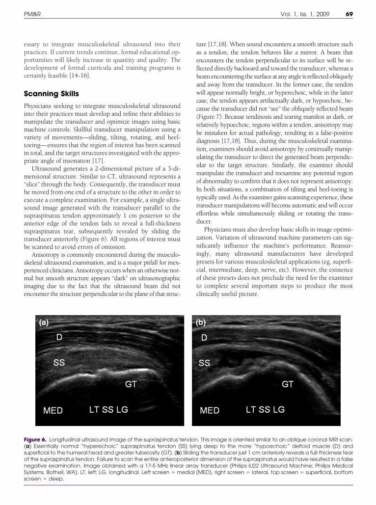
slice” through the body. Consequently, the transducer muste moved from one end of a structure to the other in order toxecute a complete examination. For example, a single ultra-ound image generated with the transducer parallel to theupraspinatus tendon approximately 1 cm posterior to thenterior edge of the tendon fails to reveal a full-thicknessupraspinatus tear, subsequently revealed by sliding theransducer anteriorly (Figure 6). All regions of interest muste scanned to avoid errors of omission.
Anisotropy is commonly encountered during the musculo-keletal ultrasound examination, and is a major pitfall for inex-erienced clinicians. Anisotropy occurs when an otherwise nor-al but smooth structure appears “dark” on ultrasonographic
maging due to the fact that the ultrasound beam did notncounter the structure perpendicular to the plane of that struc-
igure 6. Longitudinal ultrasound image of the supraspinatus ta) Essentially normal “hyperechoic” supraspinatus tendon (Superficial to the humeral head and greater tuberosity (GT). (b)f the supraspinatus tendon. Failure to scan the entire anteropoegative examination. Image obtained with a 17-5 MHz lineaystems, Bothell, WA). LT, left; LG, longitudinal. Left screen � m
creen � deep.ure [17,18]. When sound encounters a smooth structure suchs a tendon, the tendon behaves like a mirror. A beam thatncounters the tendon perpendicular to its surface will be re-ected directly backward and toward the transducer, whereas aeam encountering the surface at any angle is reflected obliquelynd away from the transducer. In the former case, the tendonill appear normally bright, or hyperechoic, while in the latter
ase, the tendon appears artifactually dark, or hypoechoic, be-ause the transducer did not “see” the obliquely reflected beamFigure 7). Because tendinosis and tearing manifest as dark, orelatively hypoechoic, regions within a tendon, anisotropy maye mistaken for actual pathology, resulting in a false-positiveiagnosis [17,18]. Thus, during the musculoskeletal examina-ion, examiners should avoid anisotropy by continually manip-lating the transducer to direct the generated beam perpendic-lar to the target structure. Similarly, the examiner shouldanipulate the transducer and reexamine any potential region
f abnormality to confirm that it does not represent anisotropy.n both situations, a combination of tilting and heel-toeing isypically used. As the examiner gains scanning experience, theseransducer manipulations will become automatic and will occurffortless while simultaneously sliding or rotating the trans-ucer.
Physicians must also develop basic skills in image optimi-ation. Variation of ultrasound machine parameters can sig-ificantly influence the machine’s performance. Reassur-
ngly, many ultrasound manufacturers have developedresets for various musculoskeletal applications (eg, superfi-ial, intermediate, deep, nerve, etc). However, the existencef these presets does not preclude the need for the examinero complete several important steps to produce the mostlinically useful picture.
. This image is oriented similar to an oblique coronal MRI scan.g deep to the more “hypoechoic” deltoid muscle (D) andthe transducer just 1 cm anteriorly reveals a full-thickness tear
r dimension of the supraspinatus would have resulted in a falsetransducer (Philips iU22 Ultrasound Machine; Philips Medical
MED), right screen � lateral, top screen � superficial, bottom
endonS) lyinSlidingsterio
r arrayedial (

ddbheotpsuwTtntgctpg
ectpcreet
oUatw
ttnt
70 Smith and Finnoff MUSCULOSKELETAL ULTRASOUND: PART 1.
First, the examiner must select the appropriate trans-ucer. Transducer choice is determined primarily by theepth of the target region. There is an inverse relationshipetween frequency and penetration depth [7]. Althoughigh-frequency transducers produce the best resolution, theyxhibit the lowest penetration into the body. Consequently,ne should always choose the highest-frequency transducerhat can adequately image the target structure(s) at the ap-ropriate depth. The superficial location of most musculo-keletal structures renders them amenable to examinationsing high-frequency (�10 MHz) linear array transducers,hich can typically penetrate up to 6 cm (Figure 1, center)he phrase “linear array” refers to the linear arrangement of
he piezoelectric crystals used in construction [7]. The ma-euverability of small-footprint, high-frequency linear arrayransducers (also called “hockey stick” transducers) providesreater flexibility when examining superficial structures lo-ated within curved body regions (eg, peroneal or posterioribial tendons about the ankle malleoli) or when performingrecise ultrasound-guided interventions in superficial re-
ions (Figure 1, left). The larger curved linear array transduc- frs typically scan at lower frequencies (2-6 MHz) and areommonly used in the hip region (Figure 1, right). Curvedransducers may also be necessary to examine shoulders inatients of large body habitus. The ability to image at in-reased depths comes at a cost. Lower-frequency scanningesults in reduced resolution, and the divergent beam geom-try of the curved transducer increases the likelihood ofncountering anisotropy when imaging smooth, linear struc-ures in the body such as tendons and ligaments.
Following transducer selection, ultrasound gel is placedn the transducer and the transducer applied to the skin.sing the depth control on the console, the examiner thendjusts the depth to a more superficial or deep setting so thathe displayed image includes the region of interest withoutasting screen space deep to the structure (Figure 8).The focal zone position is subsequently adjusted so that
he focal zone is located at the same length and position as thearget structure(s) (Figure 8). All ultrasound beams initiallyarrow to a minimum width and subsequently widen as theyravel into the body. The narrowest point of the beam, or
igure 7. (a) The transducer on the left is perpendicular to theendon, resulting in a clearly defined normal image of theendon. The transducer on the right is at an angle to theendon, which results in a poorly defined, hypoechoic ornechoic image referred to as anisotropy. (b) Transverseltrasonographic view of the proximal carpal tunnel. The me-ian nerve is outlined and appears in cross-section as a mixedensity honeycomb structure. Several hyperechoic, fibrillarnger flexor tendons (T) lie deep to the nerve. (c) Tilting theransducer slightly results in tendon anisotropy. Tendons exhibitreater anisotropy than nerves and essentially “disappear,”hereas the nerve (outlined) remains visible. Images obtainedith a 15-7 MHz small footprint linear array (ie, “hockey stick”)
ransducer (Philips iU22 Ultrasound Machine; Philips Medicalystems, Bothell, WA). Left screen � radial, right screen � ulnar,op screen � superficial, bottom screen � deep.
FtttauddfitgwwtSt
ocal zone, represents the region of best lateral resolution [6].

Lsrftmmfurssbimrsf
smtdn
egtpglAsflba
tTr9crvcafloaoc
Fsi(Ia(t
Fan�bsT“i(scattrcuiimcp“aoU
71PM&R Vol. 1, Iss. 1, 2009
ateral resolution refers to the ability to distinguish 2 adjacenttructures that occur next to each other within the imagingegion. Although lateral resolution also benefits from higher-requency scanning, it can be further enhanced by movinghe focal zone into the region of interest through electronicanipulation. Additional focal zones may be added to defineultiple target levels of interest. However, the addition of a
ocal zone requires generation and detection of a separateltrasound beam, reducing temporal resolution. Temporalesolution refers to the ability to identify the position of atructure at any point in time and is reflected on the displaycreen as frame rate (Figure 8). A faster frame rate reflectsetter temporal resolution. As focal zones are added, or
maging depth increased, the rate at which the ultrasoundachine can produce complete, updated B-mode images is
educed. One must manage frame rates based on the clinicalituation. Higher frame rates (typically more than 20
igure 8. Transverse (axial) view of an ultrasound guidedspiration of a complex prepatellar bursitis. An 18-gaugeeedle is entering from the medial side of the knee (left screen
lateral, right screen � medial, top screen � superficial,ottom screen � deep). Numerical scale on right side of
creen depicts imaging depth, set at 3 cm for this procedure.he depth was adjusted using a console control to avoidwasted space” deep to the target structure(s). The focal zone
s depicted by the vertical bar just to the left of the depth scaledelimited by the arrows). As an alternative to adding orubtracting focal zones, this machine provides the user theapability of adjusting the length (ie, tissue depth covered) ofsingle focal zone. The user uses the console controls to move
he focal zone to the region of interest, then changes its lengtho encompass the target structure(s). Temporal resolution isepresented by frame rate, appearing as FR in the left upperorner of the image. In this case, the ultrasound image is beingpdated 32 times per second (32 Hz), providing “real-time”
maging of dynamic processes such as this aspiration. The gains represented as a percent value and is depicted in the
iddle left side of the screen, in this case 83%. Using consoleontrols, the overall gain can be increased toward 100%,roviding maximal amplification (likely resulting in imagewhite out”), or reduced toward 0%, providing essentially nomplification (likely resulting in image “black out”). Imagebtained with a 12-5 MHz linear array transducer (Philips iU22ltrasound Machine; Philips Medical Systems, Bothell, WA).
rames/s) are necessary to detect rapidly occurring eventst
uch as a snapping iliopsoas tendon or to track needle move-ent and injectate flow during an ultrasound guided injec-
ion [19]. At frame rates less than 16 frames per second, theisplayed image degrades, and real-time capabilities are sig-ificantly compromised [7].
After choosing the focal zone number and location, thexaminer then adjusts the overall gain (Figure 8). The overallain control equally amplifies all of the echoes returning fromhe scanned region [7]. The gain should be adjusted torovide optimal visualization of the target region. Too muchain will result in “whiting out” of the image, whereas tooittle gain will render the target region too dark to assess.lthough the optimal overall gain for a particular scan isomewhat subjective, blood flowing within vessels, simpleuid collections, and regions beyond bone should appearlack or nearly black when the overall gain is adjustedppropriately.
Finally, the examiner adjusts the depth gain compensa-ion (DGC, also called time gain compensation, or TGC) [7].he DGC typically appears as a series of slide dials, eachepresenting the gain at a different depth in the image (Figure). By sliding a specific DGC control to the left or right, onean decrease or increase the gain, respectively, in that specificegion of the scanned image. Thus, DGC is a depth-specificariation of overall gain. Depth gain compensation exists toorrect for the normal attenuation of sound waves that occurss the waves propagate through body tissues. Although re-ected sound beams are required for image generation, mostf the sound traveling through the body is actually absorbednd dissipated as heat [6]. Attenuation results in a reductionf the acoustic energy (expressed in decibels [dB] and in-reases as a function of depth and frequency [6]. This rela-
igure 9. Console controls of modern-day cart-based ultra-ound machine (Philips iU22 Ultrasound Machine; Philips Med-cal Systems, Bothell, WA). The depth gain compensationDGC) slide controls are on the right hand side of the picture.n this case, 8 DGC slides are available, each independentlydjusting the gain at a specific level in the ultrasound image
top slide � superficial, bottom slide � deep). Moving a slide tohe left will decrease the gain at that level, whereas moving it
o the right will increase the gain at that level.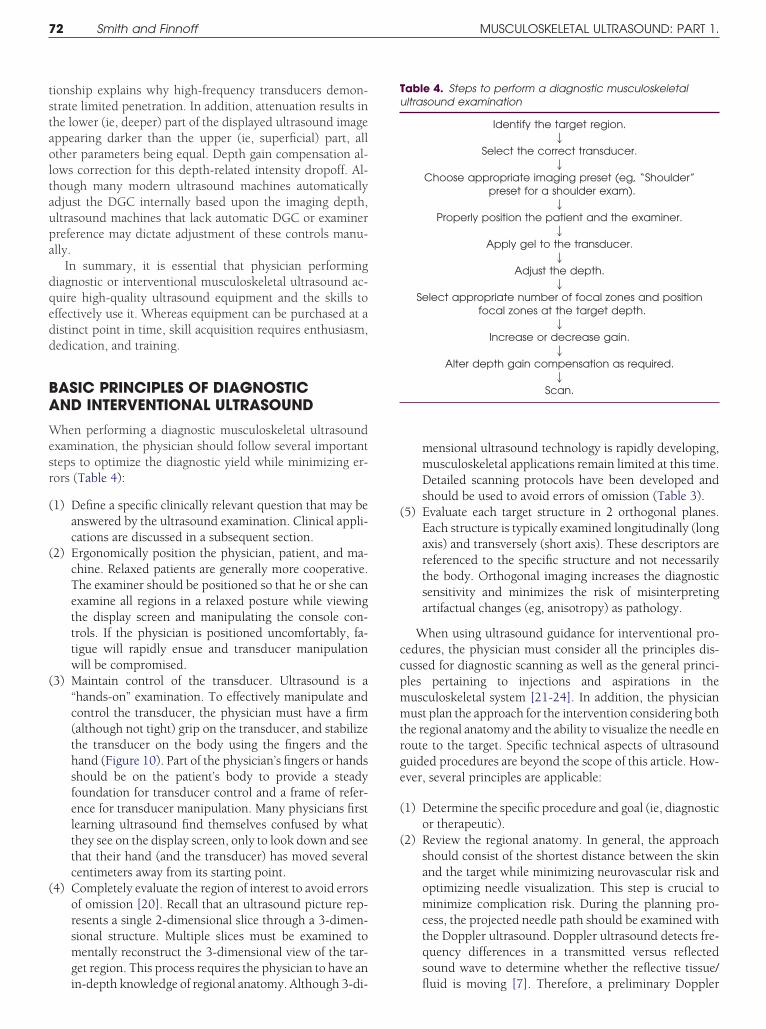
tstaoltaupa
dqedd
BA
Wesr
(
(
(
(
(
ccpmmtrge
(
(
Tu
72 Smith and Finnoff MUSCULOSKELETAL ULTRASOUND: PART 1.
ionship explains why high-frequency transducers demon-trate limited penetration. In addition, attenuation results inhe lower (ie, deeper) part of the displayed ultrasound imageppearing darker than the upper (ie, superficial) part, allther parameters being equal. Depth gain compensation al-ows correction for this depth-related intensity dropoff. Al-hough many modern ultrasound machines automaticallydjust the DGC internally based upon the imaging depth,ltrasound machines that lack automatic DGC or examinerreference may dictate adjustment of these controls manu-lly.
In summary, it is essential that physician performingiagnostic or interventional musculoskeletal ultrasound ac-uire high-quality ultrasound equipment and the skills toffectively use it. Whereas equipment can be purchased at aistinct point in time, skill acquisition requires enthusiasm,edication, and training.
ASIC PRINCIPLES OF DIAGNOSTICND INTERVENTIONAL ULTRASOUND
hen performing a diagnostic musculoskeletal ultrasoundxamination, the physician should follow several importantteps to optimize the diagnostic yield while minimizing er-ors (Table 4):
1) Define a specific clinically relevant question that may beanswered by the ultrasound examination. Clinical appli-cations are discussed in a subsequent section.
2) Ergonomically position the physician, patient, and ma-chine. Relaxed patients are generally more cooperative.The examiner should be positioned so that he or she canexamine all regions in a relaxed posture while viewingthe display screen and manipulating the console con-trols. If the physician is positioned uncomfortably, fa-tigue will rapidly ensue and transducer manipulationwill be compromised.
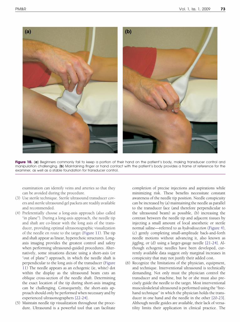
3) Maintain control of the transducer. Ultrasound is a“hands-on” examination. To effectively manipulate andcontrol the transducer, the physician must have a firm(although not tight) grip on the transducer, and stabilizethe transducer on the body using the fingers and thehand (Figure 10). Part of the physician’s fingers or handsshould be on the patient’s body to provide a steadyfoundation for transducer control and a frame of refer-ence for transducer manipulation. Many physicians firstlearning ultrasound find themselves confused by whatthey see on the display screen, only to look down and seethat their hand (and the transducer) has moved severalcentimeters away from its starting point.
4) Completely evaluate the region of interest to avoid errorsof omission [20]. Recall that an ultrasound picture rep-resents a single 2-dimensional slice through a 3-dimen-sional structure. Multiple slices must be examined tomentally reconstruct the 3-dimensional view of the tar-get region. This process requires the physician to have an
in-depth knowledge of regional anatomy. Although 3-di-mensional ultrasound technology is rapidly developing,musculoskeletal applications remain limited at this time.Detailed scanning protocols have been developed andshould be used to avoid errors of omission (Table 3).
5) Evaluate each target structure in 2 orthogonal planes.Each structure is typically examined longitudinally (longaxis) and transversely (short axis). These descriptors arereferenced to the specific structure and not necessarilythe body. Orthogonal imaging increases the diagnosticsensitivity and minimizes the risk of misinterpretingartifactual changes (eg, anisotropy) as pathology.
When using ultrasound guidance for interventional pro-edures, the physician must consider all the principles dis-ussed for diagnostic scanning as well as the general princi-les pertaining to injections and aspirations in theusculoskeletal system [21-24]. In addition, the physicianust plan the approach for the intervention considering both
he regional anatomy and the ability to visualize the needle enoute to the target. Specific technical aspects of ultrasounduided procedures are beyond the scope of this article. How-ver, several principles are applicable:
1) Determine the specific procedure and goal (ie, diagnosticor therapeutic).
2) Review the regional anatomy. In general, the approachshould consist of the shortest distance between the skinand the target while minimizing neurovascular risk andoptimizing needle visualization. This step is crucial tominimize complication risk. During the planning pro-cess, the projected needle path should be examined withthe Doppler ultrasound. Doppler ultrasound detects fre-quency differences in a transmitted versus reflectedsound wave to determine whether the reflective tissue/
able 4. Steps to perform a diagnostic musculoskeletalltrasound examination
Identify the target region.2
Select the correct transducer.2
Choose appropriate imaging preset (eg, “Shoulder”preset for a shoulder exam).
2Properly position the patient and the examiner.
2Apply gel to the transducer.
2Adjust the depth.
2Select appropriate number of focal zones and position
focal zones at the target depth.2
Increase or decrease gain.2
Alter depth gain compensation as required.2
Scan.
fluid is moving [7]. Therefore, a preliminary Doppler
(
(
(
(
Fme l.
73PM&R Vol. 1, Iss. 1, 2009
examination can identify veins and arteries so that theycan be avoided during the procedure.
3) Use sterile technique. Sterile ultrasound transducer cov-ers and sterile ultrasound gel packets are readily availableand recommended.
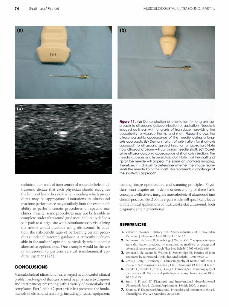
4) Preferentially choose a long-axis approach (also called“in plane”). During a long-axis approach, the needle tipand shaft are co-linear with the long axis of the trans-ducer, providing optimal ultrasonographic visualizationof the needle en route to the target (Figure 11). The tipand shaft appear as linear, hyperechoic structures. Long-axis imaging provides the greatest control and safetywhen performing ultrasound-guided procedures. Alter-natively, some situations dictate using a short-axis (or“out of plane”) approach, in which the needle shaft isperpendicular to the long axis of the transducer (Figure11) The needle appears as an echogenic (ie, white) dotwithin the display as the ultrasound beam cuts anoblique cross-section of the needle shaft. Determiningthe exact location of the tip during short-axis imagingcan be challenging. Consequently, the short-axis ap-proach should only be performed when necessary and byexperienced ultrasonographers [22-24].
5) Maintain needle tip visualization throughout the proce-
igure 10. (a) Beginners commonly fail to keep a portion ofanipulation challenging. (b) Maintaining finger or hand con
xaminer, as well as a stable foundation for transducer contro
dure. Ultrasound is a powerful tool that can facilitate
completion of precise injections and aspirations whileminimizing risk. These benefits necessitate constantawareness of the needle tip position. Needle conspicuitycan be increased by (a) maintaining the needle as parallelto the transducer face (and therefore perpendicular tothe ultrasound beam) as possible, (b) increasing thecontrast between the needle tip and adjacent tissues byinjecting a small amount of local anesthetic or sterilenormal saline—referred to as hydrodissection (Figure 4),(c) gently completing small-amplitude back-and-forthneedle motions without advancing it, also known asjiggling, or (d) using a larger-gauge needle [21-24]. Al-though echogenic needles have been developed, cur-rently available data suggest only marginal increases inconspicuity that may not justify their added cost.
6) Recognize the limitations of the physician, equipment,and technique. Interventional ultrasound is technicallydemanding. Not only must the physician control thetransducer and machine, but he or she must also pre-cisely guide the needle to the target. Most interventionalmusculoskeletal ultrasound is performed using the “free-hand technique” in which the physician holds the trans-ducer in one hand and the needle in the other [20-23].Although needle guides are available, their lack of versa-
and on the patient’s body, making transducer control andith the patient’s body provides a frame of reference for the
their htact w
tility limits their application in clinical practice. The
C
Mpacm
tcccod
R
t
74 Smith and Finnoff MUSCULOSKELETAL ULTRASOUND: PART 1.
technical demands of interventional musculoskeletal ul-trasound dictate that each physician should recognizethe limits of his or her skill when deciding which proce-dures may be appropriate. Limitations in ultrasoundmachine performance may similarly limit the examiner’sability to perform certain procedures on specific ma-chines. Finally, some procedures may not be feasible tocomplete under ultrasound guidance. Failure to define asafe path to a target site while simultaneously visualizingthe needle would preclude using ultrasound. In addi-tion, the risk-benefit ratio of performing certain proce-dures under ultrasound guidance is currently unfavor-able in the authors’ opinion, particularly when superioralternative options exist. One example would be the useof ultrasound to perform cervical transforaminal epi-dural injections [25].
ONCLUSIONS
usculoskeletal ultrasound has emerged as a powerful clinicalroblem-solving tool that can be used by physicians to diagnosend treat patients presenting with a variety of musculoskeletalomplaints. Part 1 of this 2-part article has presented the funda-
entals of ultrasound scanning, including physics, equipment,raining, image optimization, and scanning principles. Physi-ians must acquire an in-depth understanding of these basiconcepts to effectively integrate musculoskeletal ultrasound intolinical practice. Part 2 of this 2-part article will specifically focusn the clinical applications of musculoskeletal ultrasound, bothiagnostic and interventional.
EFERENCES1. Valente C, Wagner S. History of the American Institute of Ultrasound in
Medicine. J Ultrasound Med 2005;24:131-142.2. Lehmann J, de Lateur B, Stonebridge J, Warren CG. Therapeutic temper-
ature distribution produced by ultrasound as modified by dosage andvolume of tissue exposed. Arch Phys Med Rehabil 1967;48:662-666.
3. Lehman J, de Lateur B, Warren B, Stonebridge JB. Heating of jointstructures by ultrasound. Arch Phys Med Rehabil 1968;49:28-30.
4. Crass J, Craig E, Feinberg S. Ultrasonography of rotator cuff tears: areview of 500 diagnostic studies. J Clin Ultrasound 1988;16:313-327.
5. Bretzke C, Bretzke C, Crass J, Craig E, Feinberg S. Ultrasonography ofthe rotator cuff. Normal and pathologic anatomy. Invest Radiol 1985;20:311-315.
6. Smith J, Finnoff JT. Diagnostic and Interventional MusculoskeletalUltrasound: Part 2. Clinical Applications. PM&R 2009, in press.
7. Kremkau F. Diagnostic Ultrasound: Principles and Instruments. 6th ed.
igure 11. (a) Demonstration of orientation for long-axis ap-roach to ultrasound guided injection or aspiration. Needle is
maged co-linear with long-axis of transducer, providing thepportunity to visualize the tip and shaft. Figure 8 shows theltrasonographic appearance of the needle during a long-xis approach. (b) Demonstration of orientation for short-axispproach to ultrasound guided injection or aspiration. Noteow ultrasound beam will cut across needle shaft. (c) Correl-tive ultrasonographic appearance of short axis injection. Theeedle appears as a hyperechoic dot. Note that the shaft andip of the needle will appear the same on short-axis imaging.herefore, it is difficult to determine whether the image repre-ents the needle tip or the shaft. This represents a challenge ofhe short-axis approach.
FpiouaahantTs
Philadelphia, PA: WB Saunders; 2002:428.

1
1
1
1
1
1
1
1
1
1
2
2
2
2
2
2
75PM&R Vol. 1, Iss. 1, 2009
8. Khoury V, Cardinal E, Bureau N. Musculoskeletal sonography: a dy-namic tool for usual and unusual disorders. AJR Am J Roentgenol2007;188:W63-W73.
9. Farin P, Jaroma H, Harju A, Soimakillio S. Medial displacement of thebiceps brachii tendon: evaluation with dynamic sonography duringmaximal shoulder external rotation. Radiology 1995;195:845-848.
0. Jacobson J, Jebson P, Jeffers A, Fessell D, Hayes C. Ulnar nerve dislo-cation and snapping triceps syndrome: diagnosis with dynamic sonog-raphy. Radiology 2001;220:601-605.
1. Blankenbaker D, Desmet A, Keene J. Sonography of the iliopsoastendon and injection of the iliopsoas bursa for diagnosis and manage-ment of the painful snapping hip. Skelet Radiol 2007;35:565-571.
2. Teh J. Applications of Doppler imaging in the musculoskeletal system.Curr Probl Diagn Radiol 2006;35:22-34.
3. Hedrick W, Hykes D, Starchman D. Ultrasound Physics and Instru-mentation 4th ed. St. Louis, MO: Elsevier; 2005:445.
4. Taggart A, Filippucci E, Wright G, Bell A, Caims A, Meenagh G, et al.Musculoskeletal ultrasound training in rheumatology: the Belfast expe-rience. Rheumatology 2005;45:102-105.
5. Filippucci E, Meenagh G, Ciapetti A, Iagnocco A, Taggart A, Grassi W.E-learning in ultrasonography: a web-based approach. Ann Rheum Dis2007;66:962-965.
6. Filippucci E, Unlu A, Farina A, Grassi W. Sonographic training in rheu-
matology: a self-teaching approach. Ann Rheum Dis 2003;62:565-567.7. American Institute for Ultrasound in Medicine. AIUM technical bulle-tin. Transducer manipulation. J Ultrasound Med 1999;18:169-175.
8. Connolly D, Berman L, McNally E. The use of beam angulation toovercome anisotropy when viewing human tendon with high fre-quency linear array ultrasound. Br J Radiol 2001;74:183-185.
9. Pelsser V, Cardinal E, Hobden R, Aubin B, Lafortune M. Extra-articularsnapping hip: sonographic findings. AJR Am J Roentgenol 2001;176:67-73.
0. Jamadar D, Jacobson J, Caoili E, Boon TA, Dong O, Morag Y, et al.Musculoskeletal sonography technique: focused versus comprehensiveexamination. AJR Am J Roentgenol 2008;190:5-9.
1. Joines M, Motamedi K, Seeger L, DiFiori J. Musculoskeletal interven-tional ultrasound. Semin Musculoskelet Radiol 2007;11:192-198.
2. Adler R, Sofka C. Percutaneous ultrasound guided injections in themusculoskeletal system. Ultrasound Q 2003;19:3-12.
3. Adler R, Buly R, Ambrose R, Sculco T. Diagnostic and therapeutic use ofsonography-guided iliopsoas peritendinous injections. AJR Am JRoentgenol 2005;185:940-943.
4. Adler R, Allen A. Percutaneous ultrasound guided injections in theshoulder. Tech Shoulder Elbow Surg 2004;5:122-133.
5. Galiano K, Alois A, Bodner G, Freund MC, Gruber H, Maurer H, et al.Ultrasound-guided periradicular injections in the middle to lowercervical spine: an imaging study of a new approach. Reg Anesth Pain
Med 2005;30:391-396.