Embed Size (px)
Citation preview

Broadband Hardware
Manual
Building Networks for People
VPN Router
DI-804HVD-Link
07/25/2003

2
Contents
Package Contents ................................................................................3
Introduction............................................................................................4
Getting Started ....................................................................................10
Using the Configuration Menu.............................................................. 11
Networking Basics ..............................................................................68
Reset to Factory Default Settings ........................................................94
Technical Specifications ......................................................................95
Frequently Asked Questions ................................................................96
Contacting Technical Support ............................................................142
Warranty and Registration .................................................................143

3
Contents of Package:D-Link DI-804HV Broadband Hardware VPN RouterPower Adapter – 5V DCEthernet (CAT5-UTP/Straight-Through) CableManual on CDQuick Installation Guide
System Requirements For Configuration:
Computer with Windows, Macintosh, or Linux-basedoperating system with an installed Ethernet adapter
Internet Explorer version 6.x or Netscape Navigatorversion 6.x and above, with JavaScript enabled
Ethernet-Based Cable or DSL Modem
Package Contents
Note: Using a power supply with a different voltage rating than the one included with theDI-804HV will cause damage and void the warranty for this product.
If any of the above items are missing, please contact your reseller.

4
IntroductionThe D-Link DI-804HV is a 4-port Broadband Router with Virtual Private Network(VPN) functionality. It provides a complete solution for Internet surfing, officeresources sharing, and secure access to remote corporate networks.. It is anideal way to extend the reach and number of computers connected to yournetwork.
After completing the steps outlined in the Quick Installation Guide (included inyour package) you will have the ability to share information and resources.
The DI-804HV is compatible with most popular operating systems, includingMacintosh, Linux and Windows, and can be integrated into a large network.

5
Connections
Features & Benefits
Receptorfor thePowerAdapter
LAN ports provideconnections to Ethernet-enabled devices.
Broadband modem and IP sharingConnects multiple computers to a broadband (cable or DSL) modem to surfthe Internet
Auto-sensing Ethernet SwitchEquipped with a 4-port auto-sensing Ethernet switch
VPN Pass-Through supportedSupports pass-through VPN sessions and allows you to setup VPN serverand VPN clients
FirewallUnwanted packets from outside intruders can be blocked to protect yournetwork
DHCP server supportedAll of the networked computers can retrieve TCP/IP settings automaticallyfrom the DI-804HV
Web-based configurationConfigurable through any networked computer’s web browser usingNetscape or Internet Explorer
Pressing theReset Buttonrestores therouter to itsoriginal factorydefault settings.
All Ethernet ports auto-sensecable types to accommodatestraight-through or cross-overcable.
WAN port is theconnection for theEthernet cable to theCable or DSL modem
COM port providesserial connection fordial-up analog modem.
Hardware VPN Termination DeviceSupports up to 40 VPN Tunnels

6
Features & Benefits continuedAccess Control supportedAllows you to assign different access rights for different users.
Packet filter supportedPacket Filter allows you to control access to a network by analyzing theincoming and outgoing packets and letting them pass or halting thembased on the IP address of the source and destination.
Virtual Server supportedEnables you to expose WWW, FTP and other services on your LAN to beaccessible to Internet users.
User-Definable Application Sensing TunnelYou can define the attributes, for instance opening special ports to allowpackets to come through, to support special applications requiring multipleconnections, such as Internet gaming, video conferencing, and Internettelephony. The DI-804HV can sense the application type and open a multi-port tunnel for it.
DMZ Host supportedAllows a networked computer to be fully exposed to the Internet; thisfunction is used when the special “application-sensing tunnel feature” isinsufficient to allow an application to function correctly.
Introduction to BroadbandRouter TechnologyA router is a device that forwards data packets from a source to a destination. Routersforward data packets using IP addresses and not a MAC address. A router will forwarddata from the Internet to a particular computer on your LAN.
The information that resides on the Internet gets moved around using routers. Whenyou click on a link on a web page, you send a request to a server to show you the nextpage. The information that is sent and received from your computer is moved from yourcomputer to the server using routers. A router also determines the best route that yourinformation should follow to ensure that the information is delivered properly.
A router controls the amount of data that is sent through your network by eliminatinginformation that should not be there. This provides security for the computers con-nected to your router, because computers from the outside cannot access or sendinformation directly to any computer on your network. The router determines whichcomputer the information should be forwarded to and sends it. If the information is notintended for any computer on your network, the data is discarded. This keeps anyunwanted or harmful information from accessing or damaging your network.

7
Introduction to FirewallsA firewall is a device that sits between your computer and the Internet that preventsunauthorized access to or from your network. A firewall can be a computer usingfirewall software or a special piece of hardware built specifically to act as a firewall. Inmost circumstances, a firewall is used to prevent unauthorized Internet users fromaccessing private networks or corporate LAN's and Intranets.
A firewall watches all of the information moving to and from your network and analyzeseach piece of data. Each piece of data is checked against a set of criteria that theadministrator configures. If any data does not meet the criteria, that data is blockedand discarded. If the data meets the criteria, the data is passed through. This methodis called packet filtering.
A firewall can also run specific security functions based on the type of application ortype of port that is being used. For example, a firewall can be configured to work withan FTP or Telnet server. Or a firewall can be configured to work with specific UDP orTCP ports to allow certain applications or games to work properly over the Internet.
Introduction to Local Area Networking
Local Area Networking (LAN) is the term used when connecting several computerstogether over a small area such as a building or group of buildings. LAN's can beconnected over large areas. A collection of LAN's connected over a large area is calleda Wide Area Network (WAN).
A LAN consists of multiple computers connected to each other. There are many typesof media that can connect computers together. The most common media is CAT5cable (UTP or STP twisted pair wire.) Each computer must have a Network InterfaceCard (NIC), which communicates the data between computers. A NIC is usually a10Mbps network card, or 10/100Mbps network card, or a wireless network card.Wireless Local Area Networks (WLANs) do not use wires; instead they communicateover radio waves.
Most networks use hardware devices such as hubs or switches that each cable can beconnected to in order to continue the connection between computers. A hub simplytakes any data arriving through each port and forwards the data to all other ports. Aswitch is more sophisticated, in that a switch can determine the destination port for aspecific piece of data. A switch minimizes network traffic overhead and speeds up thecommunication over a network.
Networks take some time in order to plan and implement correctly. There are manyways to configure your network. You may want to take some time to determine thebest network set-up for your needs.

8
Introduction to Virtual Private NetworkingVirtual Private Networking (VPN) uses a publicly wired network (the Internet) to se-curely connect two different networks as if they were the same network. For example,an employee can access a corporate network from home using VPN, allowing theemployee to access files, databases, and other networked resources. Here are severaldifferent implementations of VPN that can be used.
Point-to-Point Tunneling Protocol (PPTP)PPTP uses proprietary means of connecting two private networks over the Internet.PPTP is a way of securing the information that is communicated between networks.PPTP secures information by encrypting the data inside of a packet.
IP Security (IPSec)IPSec provides a more secure network-to-network connection across the Internet or aWide Area Network (WAN). IPSec encrypts all communication between the client andserver whereas PPTP only encrypts the data packets.
Both of these VPN implementations are used because there is not a standard for VPNserver software. Because of this, each ISP or business can implement its own VPNnetwork making interoperability a challenge.
9
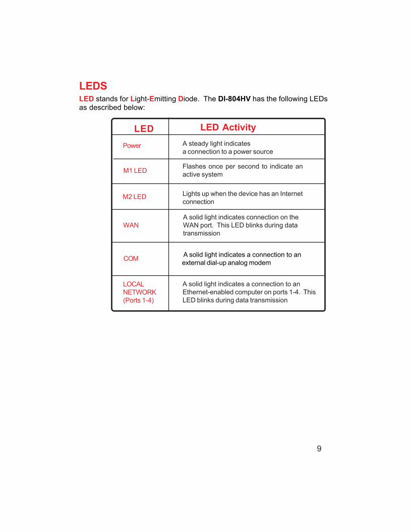
LEDSLED stands for Light-Emitting Diode. The DI-804HV has the following LEDsas described below:
LED LED Activity
Power A steady light indicatesa connection to a power sourcea power source
M2 LED Lights up when the device has an Internetconnection
WANA solid light indicates connection on theWAN port. This LED blinks during datatransmission
COM A solid light indicates a connection to anexternal dial-up analog modem
Flashes once per second to indicate anactive system
LOCALNETWORK(Ports 1-4)
A solid light indicates a connection to anEthernet-enabled computer on ports 1-4. ThisLED blinks during data transmission
M1 LED

10
For a typical network setup in a home or small office (as shown above),please do the following:
4
5
Getting Started
For additional informationabout setting up a network,see:
Networking Basics
Using the ConfigurationMenu
Consult with your Cable or DSL provider for proper installation of the modem.
1
3
2
You will need broadband Internet access (a Cable or DSL subscription line intoyour home or office).
Connect the Cable or DSL modem to the DI-804HV wireless broadband router (seethe Quick Installation Guide included with the DI-804HV.)
If you are connecting a desktop computer to your network and you need an Ethernetconnection, you can install the D-Link DFE-530TX+ Ethernet adapter into anavailable PCI slot. (See the Quick Installation Guide included with the DFE-530TX+.)
If you are connecting a laptop computer to your network, install the drivers for theEthernet Cardbus adapter (e.g., D-Link DFE-690TXD) into a laptop computer.(Seethe Quick Installation Guide included with the DFE-690TXD.)
6
You may connect an analog modem (optional) to function as a backup to the DI-804HV. To use a backup modem, you must have dial-up service.

11
Using the Configuration MenuWhenever you want to configure your network or the DI-804HV, you can access theConfiguration Menu by opening the web-browser (i.e., Internet Explorer or NetscapeNavigator) and typing in the IP Address of the DI-804HV. The DI-804HV default IPAddress is shown below:
Open the web browser Type in the IP Address of
the DI-804HV (http://192.168.0.1)
Home > Wizard
The Home>Wizard screen willappear. Please refer to theQuick Installation Guide formore information regarding theSetup Wizard.
http://192.168.0.1
Note: If you have changed the default IP Address assigned to the DI-804HV, make sure toenter the correct IP Address.
The factory default User name is admin and the defaultPassword is blank (empty). It is recommended that youchange the admin password for security purposes. Pleaserefer to Tools>Admin to change the admin password.
Clicking Apply will save changes made to the pageApply
Clicking Cancel will clear changes made to the page
Clicking Help will bring up helpful information regarding the pageHelp
Clicking Restart will restart the router. (Necessary for some changes.)
Cancel
Restart

12
Using the Configuration MenuSetup Wizard
The welcome screen outlines thesteps to complete the setupwizard. Click Next to continue.
Once you have logged in, theHome screen will appear.
Click Run Wizard
Click Next

13
Using the Configuration MenuSetup Wizard > Set Password
Old Password- This information is masked.
New Password- Type in the new password for the admin account.
Reconfirm- Type in the new password again to confirm. Click Next tocontinue with the Setup Wizard.
Click Next

14
Select Others only if you use PPTP in Europe or Big PondCable in Australia.
Using the Configuration MenuSetup Wizard > Time Zone
Select the appropriate time zone for your location-Select the proper time zone.Selections can be made byclicking on the drop down list.Click Next to continue.
Click Next
If you are unsure of which setting to select, please contactyour Internet Service Provider.
Setup Wizard > Connection Type (WAN)
Select Your Internet Connection-You will be prompted to selectthe type of internet connectionfor your router. Choose theappropriate selection and clickNext to continue.
Click Next

15
Using the Configuration MenuSetup Wizard > Set Dynamic IP Address
Host Name- Host name is the section where you input the name of yourISP. This section is optional and is not required to be filled in.
MAC Address- Each network adapter has a discrete Media Access Control(MAC) address. Note that some computer and peripherals mayalready include built-in network adapter.
Clone MACAddress-
By clicking on Clone MAC Address, the DI-804HV will auto-matically copy the MAC address of the network adapter in yourcomputer. You can also manually type in the MAC address.Click Next to continue.
If your ISP uses Dynamic IP Address, this screen will appear: (Used mainly forCable Internet service.)
Click Next

16
Using the Configuration MenuSetup Wizard > Set Static IP Address
WAN IP Address- If your ISP requires a Static IP Address, and this option is se-lected, then this screen appear. Enter the IP address informa-tion originally provided to you by your ISP. You will need tocomplete all the required fields.
WAN Subnet Mask- The subnet for the DI-804HV is preconfigured to 255.255.255.0.Configurations can be made in, but not recommended. Thisfeature is for advanced users.
WAN Gateway- This information is provided by your ISP.
Primary DNS- The Primary DNS can be found by contacting the ISP.
Secondary DNS- The Secondary DNS can be found by contacting the ISP.
If your ISP uses a Static IP Address, and this option is selected, then this screen willappear.
Click Next

17
Using the Configuration MenuSetup Wizard > PPPoE
PPPoE Account- Enter in the username provided to you by your ISP.
If your ISP uses PPPoE (Point-to-Point Protocol over Ethernet), and this option is se-lected, then this screen will appear: (Used mainly for DSL Internet service.)
PPPoE Password- Enter in the password provided to you by your ISP.
PPPoE ServiceName-
Enter in the name of your service provider. This is an optionalfield and is not necessary to be filled in.
Click Next

18
Using the Configuration MenuSetup Wizard
Configure this section only if you have an analog dial-up account. Otherwise click Nextto skip.
Dial-upTelephone-
Enter the telephone number to connect to your ISP.
Dial-up Account- This information is provided by your ISP. The Dial-up Account isalso known as username.
Dial-up Password- Enter in the password to log into your Dial-up account.
Primary DNS- The Primary DNS can be found by contacting the ISP.
Secondary DNS- The Secondary DNS can be found by contacting the ISP.
Click Next

19
Using the Configuration MenuSetup Wizard
Back- Click on Back button to go back to previous page.
Restart- Click on Restart button to finalize the settings made.
Exit- Click on Exit button to end the Setup Wizard without savingany changes.
Click Restart

20
Using the Configuration MenuHome > WAN
Choose WAN TypeWAN stands for Wide Area Network. In this case WAN represents the mode in whichyou connect to the Internet. If you are uncertain, please ask your ISP which of thefollowing represents your connection mode to the Internet:
Static IP Address- Your ISP assigns you a Static IP Address
DynamicIP Address-
Obtain an IP address from your ISP automatically (mainly forCable users)
PPPoE- Some ISPs require the use of PPPoE to connect to theirservices (mainly for DSL users)
For use in Europe only
Others-
For use in Australia only
PPTP-
Big Pond Cable-
Dial-up Network - Dial-up users can select this option to connect to their ISPthrough an analog dial-up modem if broadband connectivityis unavailable.

21
Using the Configuration MenuHome > WAN > Dynamic IP Address
Most Cable modem users will select this option to obtain an IP Address automaticallyfrom their ISP (Internet Service Provider).
Host Name- This is optional, but may be required by some ISPs. The hostname is the device name of the Router.
MAC Address- The default MAC Address is set to the WAN’s physical interfaceMAC address on the Router.
CloneMAC Address- This feature will copy the MAC address of the Ethernet card, and
replace the WAN MAC address of the Router with this Ethernetcard MAC address. It is not recommended that you change thedefault MAC address unless required by your ISP.
Primary DNSAddress-Secondary DNSAddress-
Auto-reconnect -
Input the primary DNS address provided by your ISP
(Optional) Input the Secondary DNS address provided by your ISP.
MTU- Maximum Transmission Unit; default is 1500; you may need tochange the MTU to conform to your ISP.
If enabled, the Broadband Router will automatically connect toyour ISP after your system is restarted or if the connection isdropped.
Auto-backup - Enabling this feature will connect your router to the Internet usinga dial-up service if your broadband connection becomes unavail-able. A subscription to a dial-up service is required for the auto-backup to work.

22
Using the Configuration MenuHome > WAN > Static IP Address
If you use a Static IP Address, you will input information here that your ISP has providedto you.
Secondary DNSAddress- (Optional) Input the Secondary DNS address provided by your
ISP.
Primary DNSAddress- Input the primary DNS address provided by your ISP
ISP GatewayAddress- Input the Gateway address provided by your ISP
Subnet Mask- Input the Subnet Mask provided by your ISP
IP Address- Input the IP Address provided by your ISP
MTU- Maximum Transmission Unit; default is 1500; you may need tochange the MTU to conform to your ISP.

23
Using the Configuration MenuHome > WAN > PPPoE
Most DSL users will select this option to obtain an IP address automatically from theirISP through the use of PPPoE.
MTU- Maximum Transmission Unit; default is 1492; you may need tochange the MTU to conform to your ISP.
IP Address- (Optional) Enter in the IP Address if you are assigned a staticPPPoE address.
Service Name- (Optional) Check with your ISP for more information if theyrequire the use of service name.
MaximumIdle Time- Enter a maximum idle time during which Internet connection is
maintained during inactivity. To disable this feature, enable Auto-reconnect.
(Optional) Input the secondary DNS address
Primary DNSAddress- You will get the DNS IP automatically from your ISP but you
may enter a specific DNS address that you want to use instead.
Password-
Your PPPoE username provided by your ISPUser Name-Your PPPoE password is provided by your ISP

24
Using the Configuration MenuHome > WAN > Dial-up Network
Most Dial-up users will select this option to connect to their ISP through an analogdial-up modem. This feature can be used as a back-up when your broadband connec-tivity is unavailable.
Extra Settings-
AssignedIP Address-
(Optional) Enter in the IP Address if you are assigned a staticPPPoE address.
Primary DNS-Seconday DNS-
If the settings are configured as “0.0.0.0,” they will be auto-matically assigned upon connection.
Baud Rate-
Maximum Idle Time- Enter a maximum idle time during which Internet connectionis maintained during inactivity. To disable this feature, en-able Auto-reconnect.
Dial-up Password- Password provided by your ISP
Dial-up Account-
Telephone number to connect to your ISPDial-up Telephone -Username provided by your ISP
The communication speed between the DI-804HV and yourmodem.
This setting is used to optimize the communication qualitybetween the ISP and your analog dial-up modem. (Initializa-tion string) - optional.

25
Using the Configuration MenuHome > WAN > PPTP
PPTP Password- Enter the PPTP password
PPTP Account- Enter the PPTP account name
My Subnet Mask- Enter the Subnet Mask
Connection ID- (Optional) Enter the connection ID if required by your ISP
MaximumIdle Time-
Enter a maximum idle time during which Internet connection ismaintained during inactivity. To disable this feature, enable Auto-reconnect.
My IP Address- Enter the IP Address
Server IP Address- Enter the Server IP Address
Point-to-Point Tunneling Protocol (PPTP) is a WAN connection used in Europe.

26
Using the Configuration MenuHome > WAN > BigPond Cable
User Name- Enter in the username for the BigPond account
Password- Enter the password for the BigPond account
Login Server IP- (Optional) enter the Login Server name if required
Renew IP forever- If enabled, the device will automatically connect toyour ISP after your unit is restarted or when theconnection is dropped.
Dynamic IP Address for BigPond is a WAN connection used in Australia.

27
Home > LANUsing the Configuration Menu
Domain Name- (Optional) The name of your local domain
Subnet Mask- The subnet mask of the LAN interface.The default subnet mask is 255.255.255.0.
LAN IP Address- The IP address of the LAN interface.The default IP address is: 192.168.0.1
LAN (Local AreaNetwork). This isconsidered yourinternal network.These are the IPsettings of the LANinterface for the DI-804HV. Thesesettings may bereferred to as Privatesettings. You maychange the LAN IPaddress if needed.The LAN IP addressis private to yourinternal network andcannot be seen onthe Internet.

28
Home >DHCPUsing the Configuration Menu
DHCP stands for Dynamic Host Control Protocol. The DI-804HV has a built-in DHCPserver. The DHCP Server will automatically assign an IP address to the computers onthe LAN/private network. Be sure to set your computers to be DHCP clients by settingtheir TCP/IP settings to “Obtain an IP Address Automatically.” When you turn yourcomputers on, they will automatically load the proper TCP/IP settings provided by theDI-804HV. The DHCP Server will automatically allocate an unused IP address from theIP address pool to the requesting computer. You must specify the starting and endingaddress of the IP address pool.
Starting IPAddress- The starting IP address for the DHCP server’s IP assignment.
Ending IPAddress- The ending IP address for the DHCP server’s IP assignment.
Lease Time- The length of time for the DHCP lease.
DHCP Clients List- Lists the DHCP clients connected to the DI-804HV. ClickRefresh to update the list. The table will show the Host Name,IP Address, and MAC Address of the DHCP client computer.
Enable or disable the DHCP service.DHCP Server-

29
Home >VPN SettingsUsing the Configuration Menu
VPN Settings are settings that are used to create virtual private tunnels to remoteVPN gateways. The tunnel technology supports data confidentiality, data origin,authentication and data integrity of network information by utilizing encapsulationprotocols, encryption algorithms, and hashing algorithms.
Max. number oftunnels-
Create a name for the tunnel.
NetBIOS broadcast-
Check here to enable VPN tunnels. When you are notusing the VPN feature, it is best to keep VPN disabled.
VPN -
Method- IPSec VPN supports two kinds of key-obtained methods:manual key and automatic key exchange. Manual keyapproach indicates that the two endpoint VPN gatewaysrequire setting up authentication and encryption key bythe Administrator manually. However, IKE approach willperform automatic Internet key exchange. Admins of bothendpoint gateways will only need to set the samepre-shared key.
For more in depth configuration to adjustmanual key or IKE method settings, clickMore.
More-
Tunnel Name-
Select the maximum number of allowable tunnels.
Enable this to allow NetBIOS braodcast over the VPNtunnels.

30
Remote Subnet- The subnet of the remote VPN gateway’s local network. Itcan be a host, a partial subnet or a whole subnet.
Remote Netmask- The subnet of the remote VPN gateway’s local network.It can be a host, a partial subnet or a whole subnet.
Remote Gateway- The WAN IP address of remote VPN gateway.
Home >VPN Settings > Tunnel > Method>IKEUsing the Configuration Menu
Local Subnet- The subnet of the VPN gateway’s local network. It can be ahost, a partial subnet or a whole subnet.
Local Netmask- Local netmask combined with local subnet to form a subnetdomain.
Aggressive Mode- Enabling this mode will accelerate establishing tunnel, butthe device will have less security.
Tunnel Name- Current tunnel name.
IKE Proposal index- Click the button to setup a set of frequent-used IKE proposalsand select from the set of IKE proposals for the tunnel.
IPSec Proposalindex-
Click the button to setup a set of frequent-used IPSec proposalsand select from the set of IKE proposals for the tunnel.
Preshared Key- The first key that supports IKE mechanism of both VPNgateways for negotiating further security keys. The pre-shared key must be the same for both endpoint gateways.

31
Using the Configuration MenuHome >VPN Settings > Tunnel > Method > IKE > Select IKE Proposal
IKE Proposal index-
Proposal Name-
DH Group-
Encrypt algorithm-
Auth algorithm-
A list of selected proposal indexes from the IKE proposal poollisted below.
There are three groups can be selected: group 1 (MODP768),group 2 (MODP1024), group 5 (MODP1536).
There are two algorithms that can be selected: 3DES andDES.
There are two algorithms that can be selected: SHA1 andMD5.
This is the name used to classify the IKE proposal.

32
Using the Configuration MenuHome >VPN Settings > Tunnel > Method > IKE > Select IKE ProposalContinued...
Life Time- Enter in the life time value.
Life Time Unit- There are two units that can be selected: second and KB.
Proposal ID- The identifier of IKE proposal can be chosen for addingcorresponding proposal to the dedicated tunnel.
Add to- Click it to add the chosen proposal indicated by proposal IDto IKE Proposal index list.

33
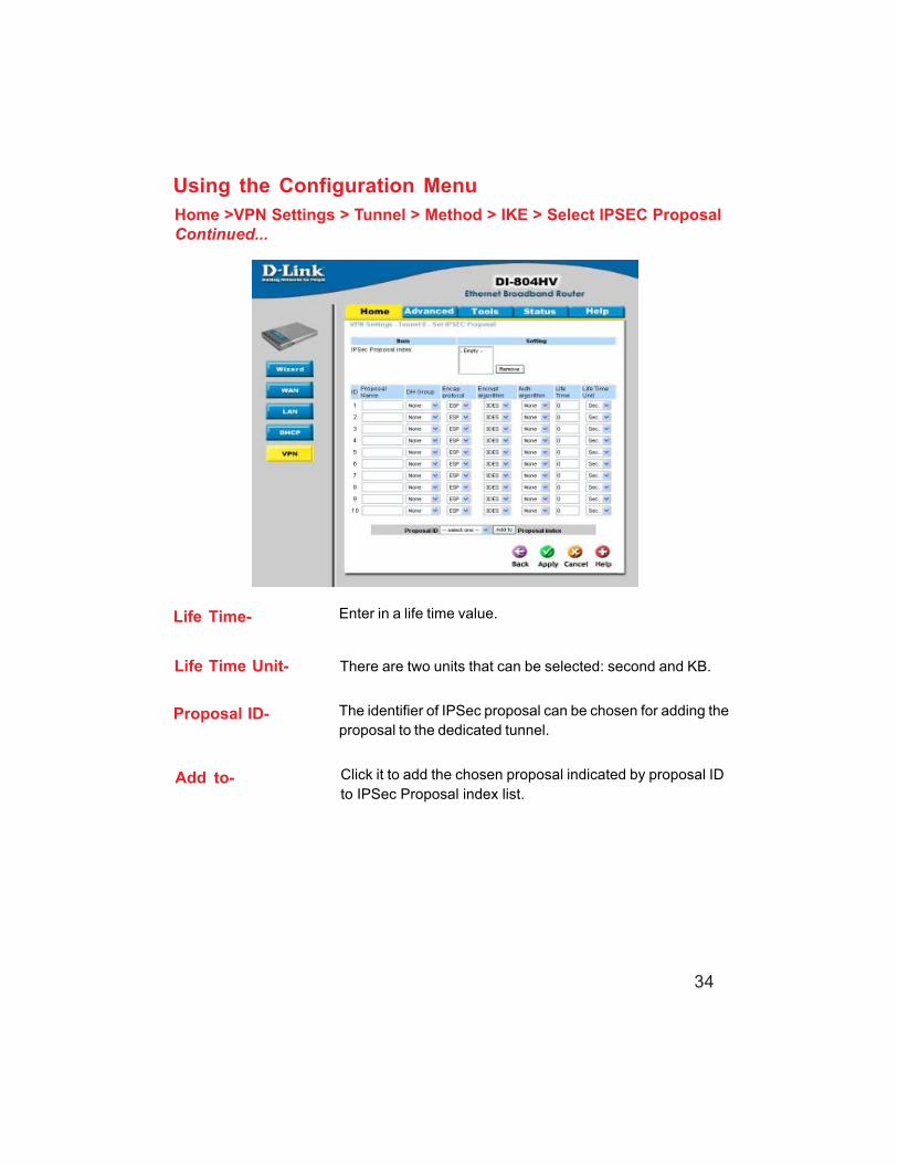
Using the Configuration MenuHome >VPN Settings > Tunnel > Method > IKE > Select IPSEC Proposal
IPSec Proposalindex-
A list of selected proposal indexes from the IPSec proposalpool listed below.
Proposal Name-
DH Group- There are three groups that can be selected: group 1(MODP768), group 2 (MODP1024), group 5 (MODP1536).
Encap protocol- There are two protocols that can be selected: ESP and AH.
Encrypt algorithm- There are two algorithms that can be selected: 3DES andDES.
This is the name used to classify the IPSec Proposal
Auth algorithm- There are two algorithms that can be selected: SHA1 andMD5.
34
Using the Configuration MenuHome >VPN Settings > Tunnel > Method > IKE > Select IPSEC ProposalContinued...
Life Time- Enter in a life time value.
Life Time Unit- There are two units that can be selected: second and KB.
Proposal ID- The identifier of IPSec proposal can be chosen for adding theproposal to the dedicated tunnel.
Add to- Click it to add the chosen proposal indicated by proposal IDto IPSec Proposal index list.

35
Using the Configuration MenuHome >VPN Settings > Tunnel > Manual
Remote Subnet- The subnet of the remote VPN gateway’s local network. Itcan be a host, a partial subnet or a whole subnet.
Remote Netmask- The subnet of the remote VPN gateway’s local network.It can be a host, a partial subnet or a whole subnet.
Remote Gateway- The WAN IP address of remote VPN gateway.
Local Subnet- The subnet of the VPN gateway’s local network. It can be ahost, a partial subnet or a whole subnet.
Local Netmask- Local netmask combined with local subnet to form a subnetdomain.
Aggressive Mode- Enabling this mode will accelerate establishing tunnel, butthe device will have less security.
Tunnel Name- Current tunnel name.
Remote SPI- The value of the remote SPI should be set in hex format.
Local SPI- The value of the local SPI should be set in hex format.
Method- The set of rules applied when connecting to the VPN gateway.

36
Using the Configuration MenuHome >VPN Settings > Tunnel > Manual Continued...
EncapsulationProtocol- There are two protocols that can be selected: ESP and AH.
EncryptionAlgorithm- There are two algorithms that can be selected: 3DES and DES.
AuthenticationAlgorithm- There are two algorithms that can be selected: SHA1 and MD5.
Encryption Key- For DES, the encryption key is 8 bytes (16 Char.). For 3DES,the encryption key is 24 bytes (48 Char.).
Authentication Key- For MD5, the authentication algorithm is16 bytes (32 Char.).For SHA1, the authentication algorithm is 20 bytes.(40 Char.).
Life Time- Enter in the life time value.
Life Time Unit- There are two units that can be selected: Second and KB.

37
Home >VPN Settings > Dynamic VPN TunnelUsing the Configuration Menu
Local Subnet- The subnet of the VPN gateway’s local network. It can be ahost, a partial subnet or a whole subnet.
Local Netmask- The netmask of the VPN gateway’s local network.
Aggressive Mode- Enabling this mode will accelerate establishing the tunnel,but the device will have less security.
Tunnel Name- Current tunnel name.
This feature works with a VPN software client so the DI-804HVdoes not need to know the IP address of the remote clients.
Dynamic VPN-
There are three parts that are necessary to setup theconfiguration of IKE for the dedicated tunnel: basic setup, IKEproposal setup, and IPSec proposal setup. Basic setupincludes the setting of following items: local subnet, localnetmask, remote subnet, remote netmask, remote gateway,and pre-shared key. The tunnel name is derived from previouspage of VPN setting. IKE proposal setup includes the settingof a set of frequent-used IKE proposals and selecting from theset of IKE proposals.
VPN Settings - IKE-

38
Using the Configuration MenuHome >VPN Settings > Dynamic VPN Tunnel Continued...
Preshared Key- The first key that supports IKE mechanism of both VPNgateways for negotiating further security keys. The pre-shared key must be the same for both endpoint gateways.
IKE Proposal index- Click the button to setup a set of frequent-used IKEproposals and select from the set of IKE proposals for thededicated tunnel.
IPSec Proposalindex-
Click the button to setup a set of frequent-used IPSecproposals and select from the set of IKE proposals for thededicated tunnel.

39
Using the Configuration MenuHome >VPN Settings > Dynamic VPN Tunnel > Set IKE Proposal
IKE Proposal index-
Proposal Name-
DH Group-
Encrypt algorithm-
Auth algorithm-
A list of selected proposal indexes from the IKE proposal poollisted below.
There are three groups can be selected: group 1 (MODP768),group 2 (MODP1024), group 5 (MODP1536).
There are two algorithms that can be selected: 3DES andDES.
It indicates which IKE proposal to be focused. First char ofthe name with 0x00 value stands for the IKE proposal is notavailable.
There are two algorithms that can be selected: SHA1 andMD5.

40
Life Time- Enter in the life time value.
Life Time Unit- There are two units that can be selected: second and KB.
Proposal ID- The identifier of IKE proposal can be chosen for addingcorresponding proposal to the dedicated tunnel.
Add to- Click it to add the chosen proposal indicated by proposal IDto IKE Proposal index list.
Using the Configuration MenuHome >VPN Settings > Dynamic VPN Tunnel > Set IKE ProposalContinued...

41
Using the Configuration MenuHome >VPN Settings > Dynamic VPN Tunnel > Set IPSEC Proposal
IPSec Proposalindex-
A list of selected proposal indexes from the IPSec proposalpool listed below.
Proposal Name-
DH Group- There are three groups that can be selected: group 1(MODP768), group 2 (MODP1024), group 5 (MODP1536).
Encap protocol- There are two protocols that can be selected: ESP and AH.
Encrypt algorithm- There are two algorithms that can be selected: 3DES andDES.
This is the name used to classify the IPSec proposal.
Auth algorithm- There are two algorithms that can be selected: SHA1 andMD5.

42
Using the Configuration MenuHome >VPN Settings > Dynamic VPN Tunnel > Set IPSEC ProposalContinued...
Life Time- Enter in a life time value.
Life Time Unit- There are two units that can be selected: second and KB.
Proposal ID- The identifier of IPSec proposal can be chosen for adding theproposal to the dedicated tunnel.
Add to- Click it to add the chosen proposal indicated by proposal IDto IPSec Proposal index list.

43
Home >VPN Settings > L2TP Server SettingUsing the Configuration Menu
Enable L2TP Server- Click to enable the L2TP Server function.
Virtual IP of L2TPServer-
Enter your Virtual IP address to access the L2PT server.
AuthenticationProtocol-
Select one of the following authentication protocols: PAP,CHAP, MSCHAP.
Tunnel Name- Current tunnel name.
User Name-
Password- Enter in the password for the L2TP account.
Enter in the username for the L2TP account.

44
Home >VPN Settings >PPTP Server SettingUsing the Configuration Menu
Enable PPTPServer-
Click to enable the PPTP Server function.
Virtual IP of PPTPServer-
Enter your Virtual IP address to access thePPPT server.
AuthenticationProtocol-
Select one of the following authentication protocols: PAP,CHAP, MSCHAP.
Tunnel Name- Current tunnel name.
User Name-
Password- Enter in the password for the PPTP account.
Enter in the username for the PPTP account.

45
Advanced > Virtual ServerUsing the Configuration Menu
The DI-804HV can be configured as a virtual server so that remote users accessing Webor FTP services via the public IP address can be automatically redirected to local serversin the LAN (Local Area Network).
The DI-804HV firewall feature filters out unrecognized packets to protect your LAN networkso all computers networked with the DI-804HV are invisible to the outside world. If youwish, you can make some of the LAN computers accessible from the Internet by enablingVirtual Server. Depending on the requested service, the DI-804HV redirects the externalservice request to the appropriate server within the LAN network.
Protocol Type- The protocol used for the virtual service.
Public Port- The port number on the WAN side that will be used to accessthe virtual service.
Private IP- The server computer in the LAN network that will be providingthe virtual services.
Name- The name referencing the virtual service.
Private Port- The port number of the service used by the Private IP computer.
Schedule- Select Always, or choose From and enter the time period dur-ing which the virtual service will be available

46
Using the Configuration MenuAdvanced > Application
Some applications require multiple connections, such as Internet gaming, videoconferencing, Internet telephony and others. These applications have difficulties workingthrough NAT (Network Address Translation). Special Applications makes some of theseapplications work with the DI-804HV. If you need to run applications that require multipleconnections, specify the port normally associated with an application in the Triggerfield, then enter the public ports associated with the trigger port into the IncomingPorts field.
At the bottom of the screen, there are already defined special applications. To usethem, select one from the drop down list and select an ID number you want to use.Then click the “Copy to” button and the router will fill in the appropriate information tothe list. You will then need to enable the service. If the mechanism of Special Applica-tions fails to make an application work, try using DMZ host instead.
Note! Only one PC can use each Special Application tunnel.
Trigger Port- This is the port used to trigger the application. It can be eithera single port or a range of ports.
Public Ports- This is the port number on the WAN side that will be used toaccess the application. You may define a single port or a rangeof ports. You can use a comma to add multiple ports or portranges.
Enabled- Select to activate the policy

47
Using the Configuration MenuAdvanced > IP Filter
IP Filter-Use IP Filters to deny LAN IP addresses access to the internet
Schedule-
IP Address-Enter in the IP address range of the computers that you want the policy to apply to. If itis only a single computer that you want the policy applied to, then enter the IP address ofthat computer in the Start Source IP and leave the End Source IP blank.
Use IP (Internet Protocol)filters to allow or denycomputers access to theInternet based on their IPaddress.
Port Range-Enter in the port range of the TCP/UDP ports that you want the policy to apply to. If it isonly a single port that you want the policy applied to, then enter the port number in theStart Port field and leave the End Port field blank. If you want to use all the ports, youcan leave the port range empty.
Enabled or Disabled-Click Enabled to apply the filter policy or click Disabled to enter an inactive filter policy(You can reactivate the policy later.)
Select Always, or choose From and enter the time period during which the IP filter policywill be in effect.
48
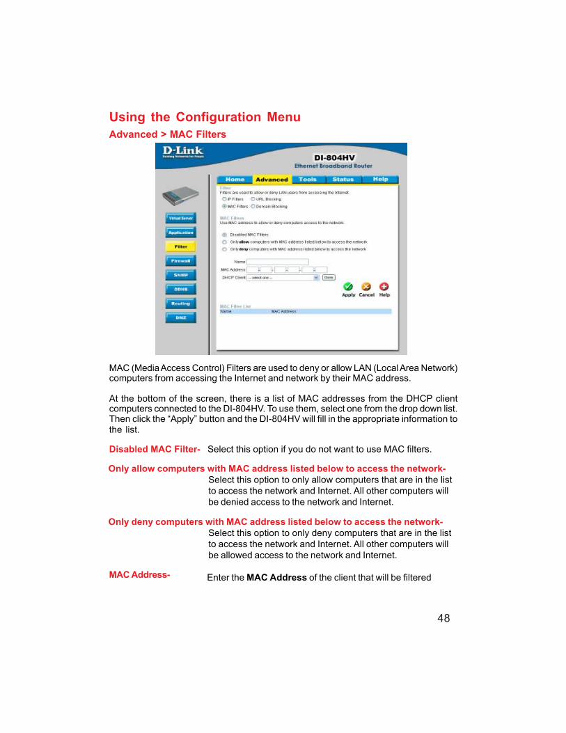
Using the Configuration MenuAdvanced > MAC Filters
MAC (Media Access Control) Filters are used to deny or allow LAN (Local Area Network)computers from accessing the Internet and network by their MAC address.
At the bottom of the screen, there is a list of MAC addresses from the DHCP clientcomputers connected to the DI-804HV. To use them, select one from the drop down list.Then click the “Apply” button and the DI-804HV will fill in the appropriate information tothe list.
Disabled MAC Filter- Select this option if you do not want to use MAC filters.
Only allow computers with MAC address listed below to access the network-Select this option to only allow computers that are in the listto access the network and Internet. All other computers willbe denied access to the network and Internet.
Only deny computers with MAC address listed below to access the network-Select this option to only deny computers that are in the listto access the network and Internet. All other computers willbe allowed access to the network and Internet.
Enter the MAC Address of the client that will be filteredMAC Address-

49
Using the Configuration MenuAdvanced > URL Blocking
Use URL Blocking to deny LAN computers from accessing specific web sites by itsURL. A URL is a specially formatted text string that defines a location on the Internet.If any part of the URL contains the blocked word, the site will not be accessible andthe web page will not display.
Disabled URL Blocking-Select this option if you do not want to use URL Blocking.

50
Using the Configuration MenuAdvanced > Domain Blocking
Use Domain Blocking to allow or deny computers access to specific Internet domainswhether it is through www, ftp, snmp, etc.
Disabled Domain Blocking-Select this option if you do not want to use Domain Blocking.
Allow users to access all domains except “Blocked Domains”-Select this option to allow users to access the specified Internet domains listed below.Users will be denied access to all other Internet domains.
Deny users to access all domains except “Permitted Domains”-Select this option to deny users to access the specified Internet domains listed below.Users will be allowed access to all other Internet domains.

51
Using the Configuration MenuAdvanced > Firewall
Firewall Rules is an advance feature used to deny or allow traffic from passing throughthe device. It works in the same way as IP Filters with additional settings. You cancreate more detailed rules for the device.
Enabled or Disabled-Click Enabled to apply the filter policy or click Disabled to enter an inactive filter policy(You can reactivate the policy later).Name-Enter the name of the Firewall Rule.Action-Select Allow or Deny to allow or deny traffic to pass through the DI-804HV.
Source-Choose between a LAN or WAN source. An asterisk signifies the selection of bothsources.IP Start-The starting IP address for the filter policy. Leaving the field blank selects all IPs.
IP End-The ending IP address for the filter policy. Leaving the field blank sleects all IPs.
Destination-Choose between a LAN or WAN destination. An asterisk signifies the selection of bothdestinations.

52
Using the Configuration MenuAdvanced > Firewall Continued
Schedule-Select Always, or choose From and enter the time period during which the virtual ser-vice will be available
IP Address-Enter in the IP address range of the computers that you want the policy to apply to. If itis only a single computer that you want the policy applied to, then enter the IP address ofthat computer in the Start Source IP and leave the End Source IP blank.
Port Range-Enter in the port range of the TCP/UDP ports that you want the policy to apply to. If it isonly a single port that you want the policy applied to, then enter the port number in theStart Port field and leave the End Port field blank. If you want to use all the ports, youcan leave the port range empty.
Protocol-Select one of the following protocols: TCP, UDP, or ICMP

53
Using the Configuration MenuAdvanced > SNMP
SNMP (Simple Network Management Protocol) is a widely used network monitoring andcontrol protocol that reports activity on each network device to the administrator of thenetwork. SNMP can be used to monitor traffic and statistics of the DI-804HV. The DI-804HV supports SNMP v1 or v2c
Enable SNMP-
Get Community-
(Simple Network Management Protocol)
Enter the password public in this field to allow “Read only” ac-cess to network administration using SNMP. You can view thenetwork, but no configuration is possible wth this setting.
Set Community- Enter the password private in this field to gain “Read and Write”access to the network using SNMP software. The administra-tor can configure the network with this setting.
Local-
Remote- WAN (Wide Area Network)
LAN (Local Area Network)
SNMP v1- Simple Network Management Protocol (SNMP) is an applica-tion layer protocl that facilitates the exchange of managementinformation between nework devices.
SNMP v2- Enhanced version of SNMP v1 with additional protocol opera-tions such as UDP, IP, CLNS, DDP, and IPX.

54
Using the Configuration MenuTools > DDNS
DDNS (Dynamic Domain Name System) keeps dynamic IP addresses (e.g., IPaddresses assigned by a DHCP capable router or server) linked to a domain name.Users who have a Dynamic DNS account may use this feature on the DI-804HV.
DDNS- When an IP address is automatically assigned by a DHCP server,DDNS automatically updates the DNS server. Select Disabledor Enabled
Provider- Select from the pull-down menu
Host Name- Enter the Host name
Username/Email- Enter the username or email address
Password/Key- Enter the password or key

55
Using the Configuration MenuAdvanced > Routing
Dynamic Routing Settings allow the VPN Router to route IPpackets to another network automatically. The RIP protocolis applied, and broadcasts the routing information to otherrouters on the network regularly.By default, it is set to disable. Check to enable (RIPv1 / RIPv2)protocol.
Dynamic Routing-
RIP v1- Protocol in which the IP address is routed through the internet.
RIP v2- Enhanced version of RIP v1with added features such as Au-thentication, Routing Domain, Next Hop Fowarding, and Subnet-mask Exchange.

56
Using the Configuration MenuAdvanced > DMZ
If you have a computer that cannot run Internet applications properly from behind theDI-804HV, then you can allow that computer to have unrestricted Internet access. Enterthe IP address of that computer as a DMZ (Demilitarized Zone) host with unrestrictedInternet access. Adding a client to the DMZ may expose that computer to a variety ofsecurity risks; so only use this option as a last resort.

57
Using the Configuration MenuTools> Admin
Password-
RemoteManagement-
To change the passwords, enter the new password twice toconfirm.
You can change the admin and user passwords here. It is recommended that youchange the admin password from the default setting. The default passwords are blank(no password).
Remote Management allows the device to be configuredthrough the WAN (Wide Area Network) port from the Internetusing a web browser. A username and password is stillrequired to access the browser-based management inter-face.
IP Address-Internet IP Address of the computer that has access to theDI-804HV. If the IP Address is set to 0.0.0.0, this allows allInternet IP addresses to access the DI-804HV.
Port-The port number used to access the DI-804HV.E.g., http://x.x.x.x:8080, where x.x.x.x. is the WAN IP addressof the DI-804HV and 8080 is the port used for the Web Manage-ment interface.

58
Using the Configuration MenuTools> Time
Enable NTP- Select to enable NTP and synchronize the time settings onyour network using an NTP server
Set the time here by entering it manually or use NTP (Network Time Protocol.) NTP isstandard protocol on the Internet that synchronizes the time settings accurately for theDI-804HV.
Default NTPserver- If you are enabling NTP, please enter the link to the default server.
Time Zone- Select your time zone from the pull-down menu
Set Device Dateand Time-
If you are entering the time manually, select the correct Year;Month; Day; Hour; Minute and Second

59
Using the Configuration MenuTools > System
Click Backup Setting to save the current settings to the localHard Drive
Click Browse to find the settings file, then click Load
Save Settings toLocal Hard Drive-
Load Settings fromLocal Hard Drive-
Restore to FactoryDefault Settings- Click Restore to Default to restore the factory default settings
The current system settings can be saved as a file onto the local hard drive. Thesaved file or any other saved setting file created by the DI-804HV can be uploadedinto the unit. To reload a system settings file, click on Browse to search the localhard drive for the file to be used. The device can also be reset back to factory defaultsettings by clicking on the Reset to Default button. Use the restore feature only ifnecessary. This will erase previously saved settings for the unit. Make sure to saveyour system settings to the hard drive before doing a factory restore.

60
Using the Configuration MenuTools > Firmware
Browse- After you have downloaded the new firmware, click Browse inthis window to locate the firmware update on your hard drive.Click Apply to complete the firmware upgrade.
Note! Do not power off the unit when it is being upgraded. When theupgrade is complete, the unit will be restarted automatically.
You can upgrade the firmware by using this tool. First, check the D-Link support site forfirmware updates at http://support.dlink.com. Make sure that the firmware you want touse is saved on the local hard drive of your computer. Click on Browse to search thelocal hard drive for the firmware that you downloaded from the D-Link website to be usedfor the update. Upgrading the firmware will not change any of your system settings butit is recommended that you save your system settings before doing a firmware upgrade.

61
Using the Configuration MenuTools > Misc
Block WAN Ping- Click Enable to block the WAN ping. Computers on the Internetwill not get a reply back from the DI-804HV when it is being“ping”ed. This may help to increase security.
Restart Device- Click Reboot to restart the unit.
Ping Test- In the open box, enter an URL (i.e. www.dlink.com) or an IP ad-dress and click on Ping to test your internet connection.
SPI Mode- When this feature is enabled, the router will record the packetinformation passed through the router such as IP address, portaddress, ACK, SEQ number, and so on. The router will alsocheck every incoming packet to detect if it is valid.
DoS- When DoS is enabled, the router will prevent Denial of Serviceattacks on all computers connected to the DI-804HV.

62
Using the Configuration MenuTools > Misc Continued...
Non-standardFTP port-
If an FTP server you want to access is not using the standard port21, then enter in the port number that the FTP server is using in-stead.
UPnP- UPnP is short for Universal Plug and Play which is a networkingarchitecture that provides compatibility among networking equip-ment, software, and peripherals. The DI-804HV is a UPnP enabledrouter and will only work with other UPnP devices/softwares. If youdo not want to use the UPnP Functionality, it can be disabled byselecting “Disabled”.
VPN Pass-Through-
The device supports VPN (Virtual Private Network) pass-through forboth PPTP (Point-to-Point Tunneling Protocol) and IPSec (IP Secu-rity). ONce VPN pass-through is enabled, there is no need to openup virtual services. Multiple VPN connections can be made throughthe device. This is useful when you have many VPN clients on theLAN.

63
Using the Configuration MenuStatus > Device Info
This screen displays information about the DI-804HV
DHCP Renew- Click to refresh IP addresses sent from the DHCP server.
DHCP Release- Click to release IP addreses sent from the DHCP server.

64
Using the Configuration MenuStatus > Log
This screen displays activities occurring on the DI-804HV.
Log Settings- Click for advanced features (see next page.)
First Page- Click First Page to go to the first page of the log.
Last Page- Click Last Page to go to the last page of the log.
Previous- Click Previous to go to the previous page of the log.
Next- Click Next to go to the next page of the log.
Clear- Click Clear to clear the current page of the log.

65
Using the Configuration MenuStatus > Log Settings
Email Address- Enter in the email address of the recipient who will receive theemail log.
Enter in the IP address of a syslog server within the network.Click Enable to activate the policy. The DI-804HV will send allof it’s logs to the specified syslog server.
IP Address of theSyslog Server-
E-Mail Alert- The DI-804HV can be set up to send the log files to a specificemail address.
SMTP Server IP- Enter in the IP address of the mail server.
Send Mail Now- Click to send mail immediately.
Log Type- Select the types of activity to log. By default, all values areselected.
66
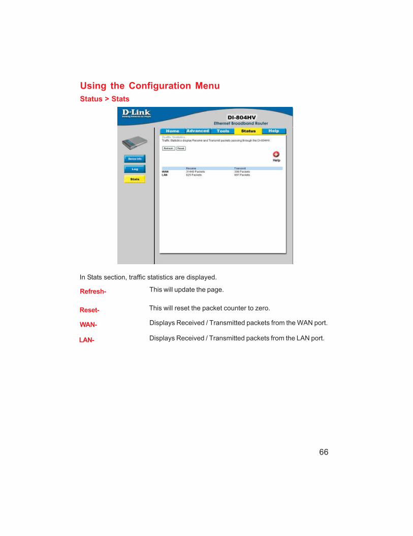
Using the Configuration MenuStatus > Stats
In Stats section, traffic statistics are displayed.
Refresh- This will update the page.
Reset- This will reset the packet counter to zero.
WAN- Displays Received / Transmitted packets from the WAN port.
LAN- Displays Received / Transmitted packets from the LAN port.

67
Using the Configuration MenuHelp
This screen displays the complete Help menu. For help at anytime, click the Help tabin the Configuration menu.

68
Using the Network Setup Wizard in Windows XP
In this section you will learn how to establish a network at home or work,using Microsoft Windows XP.
Note: Please refer to websites such as http://www.homenethelp.comand http://www.microsoft.com/windows2000 for information about networking
computers using Windows 2000, ME or 98.
Go to Start>Control Panel>Network ConnectionsSelect Set up a home or small office network
Networking Basics
When this screen appears, Click Next.
69
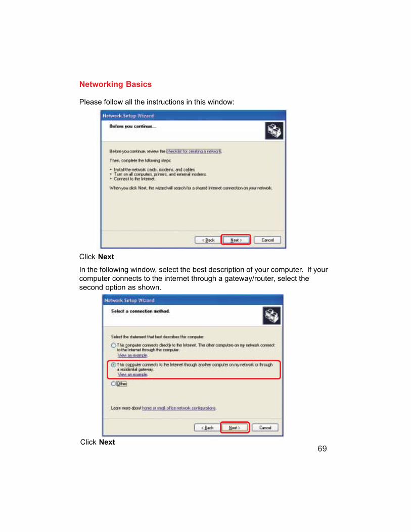
Please follow all the instructions in this window:
Networking Basics
Click Next
In the following window, select the best description of your computer. If yourcomputer connects to the internet through a gateway/router, select thesecond option as shown.
Click Next

70
Enter a Computer description and a Computer name (optional.)
Networking Basics
Click NextEnter a Workgroup name. All computers on your network should have thesame Workgroup name.
Click Next

71
Please wait while the Network Setup Wizard applies the changes.
Networking Basics
When the changes are complete, click Next.
Please wait while the Network Setup Wizard configures the computer.This may take a few minutes.

72
Networking BasicsIn the window below, select the option that fits your needs. In this example, Create aNetwork Setup Disk has been selected. You will run this disk on each of thecomputers on your network. Click Next.
Insert a disk into the Floppy Disk Drive, in this case drive A.

73
Networking Basics
Please read the information under Here’s how in the screen below. After you completethe Network Setup Wizard you will use the Network Setup Disk to run the NetworkSetup Wizard once on each of the computers on your network. To continue click Next.

74
Networking BasicsPlease read the information on this screen, then click Finish to complete theNetwork Setup Wizard.
The new settings will take effect when you restart the computer. Click Yes torestart the computer.
You have completed configuring this computer. Next, you will need to run theNetwork Setup Disk on all the other computers on your network. After run-ning the Network Setup Disk on all your computers, your new wireless net-work will be ready to use.

75
Networking BasicsNaming your ComputerTo name your computer, please follow these directions: In Windows XP:
Click Start (in the lower left corner of the screen)
Right-click on My Computer
Select Properties and click
Select the ComputerName Tab in the SystemProperties window.
You may enter a Com-puter Description if youwish; this field is optional.
To rename the computerand join a domain, ClickChange.

76
Networking BasicsNaming your Computer
In this window, enter theComputer name
Select Workgroup and enterthe name of the Workgroup
All computers on your networkmust have the sameWorkgroup name.
Click OK
Checking the IP Address in Windows XP
The wireless adapter-equipped computers in your network must be in the same IP Ad-dress range (see Getting Started in this manual for a definition of IP Address Range.) Tocheck on the IP Address of the adapter, please do the following:
Right-click on theLocal AreaConnection iconin the task bar
Click on Status
OK

Networking BasicsChecking the IP Address in Windows XP
This window will appear.
Click theSupport tab
Click Close
Assigning a Static IP Address in Windows XP/2000
Note: Residential Gateways/Broadband Routers will automatically assign IP Ad-dresses to the computers on the network, using DHCP (Dynamic Host Configura-tion Protocol) technology. If you are using a DHCP-capable Gateway/Router youwill not need to assign Static IP Addresses.If you are not using a DHCP capable Gateway/Router, or you need to assign a Static IPAddress, please follow these instructions:
Go to Start
Double-click onControl Panel
75

78
Networking BasicsAssigning a Static IP Address in Windows XP/2000
Double-click onNetworkConnections
Click on Properties
Right-click on Local AreaConnections

79
Networking BasicsAssigning a Static IP Addressin Windows XP/2000
The DNS server information will be supplied by your ISP (Internet Service Provider.)
Click OK
Enter the LAN IP address ofthe Wireless Router. (D-Linkwireless routers have a LAN IPaddress of 192.168.0.1)
Enter the LAN IP address ofthe Wireless Router. (D-Linkwireless routers have a LAN IPaddress of 192.168.0.1)
192 168 0 1
192 168 0 1
In the window below, input your IPaddress, subnet mask, defaultgateway and DNS server address.(The IP Addresses on your networkmust be within the same range. Forexample, if one computer has an IPAddress of 192.168.0.2, the othercomputers should have IP Addressesthat are sequential, like 192.168.0.3and 192.168.0.4. The subnet maskmust be the same for all the computerson the network.)
Select Use the following DNSserver addresses.
IP Address:e.g., 192.168.0.2
Subnet Mask:255.255.255.0
Click on Internet Protocol (TCP/IP)
Click Properties

80
Networking BasicsAssigning a Static IP Address with Macintosh OSX
Go to the Apple Menu and se-lect System Preferences
cClick on Network
Select Built-in Ethernet in theShow pull-down menu
Select Manually in the Con-figure pull-down menu
Input the Static IP Address,the Subnet Mask and theRouter IP Address in the ap-propriate fields
Click Apply Now

81
Networking BasicsSelecting a Dynamic IP Address with Macintosh OSX
Go to the Apple Menu and selectSystem Preferences
Click on Network
Select Built-in Ethernet in theShow pull-down menu
Select Using DHCP in theConfigure pull-down menu
Click Apply Now
The IP Address, Subnetmask, and the Router’s IPAddress will appear in a fewseconds

82
Networking BasicsAdding and Sharing Printers in Windows XP
After you have run the Network Setup Wizard on all the computers in your network(please see the Network Setup Wizard section at the beginning of Networking Basics,)you can use the Add Printer Wizard to add or share a printer on your network.
Whether you want to add a local printer (a printer connected directly to one computer,)share an LPR printer (a printer connected to a print server) or share a network printer(a printer connected to your network through a Gateway/Router,) use the Add PrinterWizard. Please follow the directions below:
First, make sure that you have run the Network Setup Wizard on all of the computerson your network.
On the following pages, we will show you these 3 ways to use the Add Printer Wizard:
1. Adding a local printer
2. Sharing an network printer
3. Sharing an LPR printer
For help with other tasks, that we have not covered here, in home or small office net-working, see Using the Shared Documents folder and Sharing files and folders inthe Help and Support Center in Microsoft Windows XP.
(Other Networking Tasks)

83
Networking BasicsAdding a local printer (a printer connected directly to a computer)
A printer that is not shared on the network and is connected directly to one computeris called a local printer. If you do not need to share your printer on a network, followthese directions to add the printer to one computer.
Go toStart>Printersand Faxes
Click on Add a printer

84
Networking BasicsAdding a local printer
Click Next
Select Local printerattached to thiscomputer
(Deselect Automati-cally detect and installmy Plug and Playprinter if it has beenselected.)
Click Next
Select Use the follow-ing port:
From the pull-down menuselect the correct portfor your printer
(Most computers use the LPT1: port,as shown in the illustration.)
Click Next

85
Networking BasicsAdding a local printer
Select and highlightthe correct driver foryour printer.
Click Next
(If the correct driver isnot displayed, insert theCD or floppy disk thatcame with your printerand click Have Disk.)
At this screen, youcan change the nameof the printer (optional.)
Click Next
Select Yes, to print atest page. A successfulprinting will confirm thatyou have chosen thecorrect driver.
Click Next

86
Networking BasicsAdding a local printer
This screen gives you information about your printer.
Click Finish
When the test page has printed,
Click OK

87
Networking BasicsAdding a local printer
Go to Start> Printersand Faxes
A successful installation will displaythe printer icon as shown at right.
You have successfully added a localprinter.
Sharing a network printerAfter you have run the Network Setup Wizard on all the computers on your network,you can run the Add Printer Wizard on all the computers on your network. Pleasefollow these directions to use the Add Printer Wizard to share a printer on yournetwork:
Go to Start>Printers and Faxes

88
Networking BasicsSharing a network printer
Click onAdd a printer
Click Next
SelectNetwork Printer
Click Next

89
Networking BasicsSharing a network printer
Select Browse fora printer
Click Next
Select the printer youwould like to share
Click Next
Click Finish

90
Networking BasicsSharing a network printer
To check for properinstallation:
Go to Start > Printersand Faxes
The printer icon will appear at right,indicating proper installation.
You have completed adding theprinter.
To share this printeron your network:
Remember the printername
Run the Add PrinterWizard on all thecomputers on yournetwork
Make sure you havealready run theNetwork SetupWizard on all thenetwork computers
After you run the Add PrinterWizard on all the computers in thenetwork, you can share the printer.
91
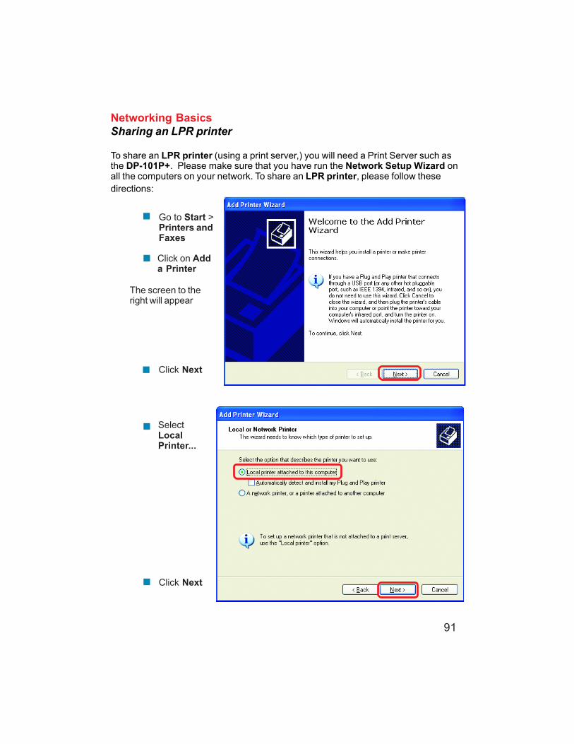
Networking BasicsSharing an LPR printer
To share an LPR printer (using a print server,) you will need a Print Server such asthe DP-101P+. Please make sure that you have run the Network Setup Wizard onall the computers on your network. To share an LPR printer, please follow thesedirections:
Go to Start >Printers andFaxes
Click on Adda Printer
The screen to theright will appear
Click Next
SelectLocalPrinter...
Click Next

92
Networking BasicsSharing an LPR printer
Click Next
Select Keep existingdriver
If the printer driver is already installed, dothe following:
Click Have Disk
Insert the printer driver disk thatcame with your printer.
Select the printer youare adding from the listof Printers.
Click Finish
This screen will show youinformation about yourprinter.

93
Networking BasicsSharing an LPR printer
Note: You must run the Network Setup Wizard on all the computers on your network beforeyou run the Add Printer Wizard.
Please run the Add PrinterWizard on all the computerson your network in order toshare the printer.
Click Finish to complete theaddition of the printer.
This screen will display informationabout your printer.
Click Next
Select Yes, to print a test page.
Click Next
Please remember the name ofyour printer. You will need thisinformation when you use theAdd Printer Wizard on theother computers on yournetwork.
You can rename your printer ifyou choose. It is optional.

94
After you have tried other methods for troubleshooting your network, youmay choose to Reset the DI-804HV to the factory default settings.
To hard-reset the D-Link DI-804HV to the Factory Default Settings, please dothe following:
Resetting the DI-804HV to theFactory Default Settings
Use a paper clip to press the Reset button andpower on.
Locate the Reset button on the back of the DI-804HV
After you have completed the above steps, the DI-804HVwill be reset to the factory default settings
Hold for about 5 seconds (don’t hold too long) andthen release. (Or, release when M1 and M2 flashat the same time.)

95
Technical Specifications
VPN Pass Through FunctionPPTPL2TPIPSec
Device Management
StandardsIEEE 802.3 10BASET-T Ethernet
IEEE 802.3x Flow ControlIEEE 802.3u 100BASE-TX Fast Ethernet
ANSI/IEEE 802.3 NWay auto-negotiation
Web-Based – Internet Explorer 6x or later; Netscape Navigator 6x orlater; or other Java- enabled browsers.
LEDsWANLANM1M2
Operating Temperature41°F to 131°F ( 5°C to 55°C)
Humidity10-90%
PowerDC 5V
L = 7.56 inches (192mm)W = 4.65 inches (48mm)H = 1.22 inches (31mm)
Dimensions
~10.8 oz. (0.3 kg)Weight
4 x NWay 10BASE-T/100BASE-TX Fast Ethernet LAN (Media Auto Sensing)1 x NWay 10BASE-T/100BASE-TX Fast Ethernet WAN (Media Auto Sensing)1 Com Port (Dial-Up Modem)
Ports
COM

96
Frequently Asked Questions
When entering the IP Address of the DI-804HV (192.168.0.1), you are not connectingto the Internet or have to be connected to the Internet. The device has the utility built-in to a ROM chip in the device itself. Your computer must be on the same IP subnetto connect to the web-based utility.
To resolve difficulties accessing a web utility, please follow the steps below.
Step 1 Verify physical connectivity by checking for solid link lights on the device. Ifyou do not get a solid link light, try using a different cable or connect to a differentport on the device if possible. If the computer is turned off, the link light may not beon.
The following connections require a Crossover Cable:Computer to ComputerComputer to Uplink PortComputer to Access PointComputer to Print ServerComputer/XBOX/PS2 to DWL-810Computer/XBOX/PS2 to DWL-900AP+Uplink Port to Uplink Port (hub/switch)Normal Port to Normal Port (hub/switch)
The following connections require a Straight-through Cable:Computer to Residential Gateway/RouterComputer to Normal Port (hub/switch)Access Point to Normal Port (hub/switch)Print Server to Normal Port (hub/switch)Uplink Port to Normal Port (hub/switch)
Rule of Thumb:”If there is a link light, the cable is right.”
What type of cable should I be using?
Why can´t I access the web based configuration?

97
Frequently Asked Questions (continued)
What type of cable should I be using? (continued)What´s the difference between a crossover cable and a straight-throughcable?The wiring in crossover and straight-through cables are different. The two typesof cable have different purposes for differentLAN configurations. EIA/TIA 568A/568Bdefine the wiring standards and allow fortwo different wiring color codes asillustrated in the following diagram.
*The wires with colored backgrounds mayhave white stripes and may be denotedthat way in diagrams found elsewhere.
How to tell straight-through cable froma crossover cable:The main way to tell the differencebetween the two cable types is to comparethe wiring order on the ends of the cable. Ifthe wiring is the same on both sides, it isstraight-through cable. If one side has opposite wiring, it is a crossover cable.
All you need to remember to properly configure the cables is the pinout order ofthe two cable ends and the following rules:A straight-through cable has identical endsA crossover cable has different ends
It makes no functional difference which standard you follow for straight-throughcable ends, as long as both ends are the same. You can start a crossover cablewith either standard as long as the other end is the other standard. It makes nofunctional difference which end is which. The order in which you pin the cable isimportant. Using a pattern other than what is specified in the above diagramcould cause connection problems.
When to use a crossover cable and when to use a straight-through cable:Computer to Computer – CrossoverComputer to an normal port on a Hub/Switch – Straight-throughComputer to an uplink port on a Hub/Switch - CrossoverHub/Switch uplink port to another Hub/Switch uplink port – CrossoverHub/Switch uplink port to another Hub/Switch normal port - Straight-through
Why can´t I access the web based configuration? (continued)
98
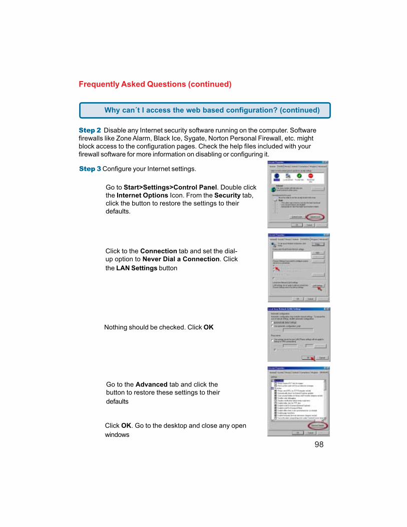
Step 3 Configure your Internet settings.
Step 2 Disable any Internet security software running on the computer. Softwarefirewalls like Zone Alarm, Black Ice, Sygate, Norton Personal Firewall, etc. mightblock access to the configuration pages. Check the help files included with yourfirewall software for more information on disabling or configuring it.
Frequently Asked Questions (continued)
Click to the Connection tab and set the dial-up option to Never Dial a Connection. Clickthe LAN Settings button
Nothing should be checked. Click OK
Go to the Advanced tab and click thebutton to restore these settings to theirdefaults
Click OK. Go to the desktop and close any openwindows
Go to Start>Settings>Control Panel. Double clickthe Internet Options Icon. From the Security tab,click the button to restore the settings to theirdefaults.
Why can´t I access the web based configuration? (continued)

99
Frequently Asked Questions (continued)
Step 4 Check your IP Address. Your computer must have an IP Address in the samerange of the device you are attempting to configure. Most D-Link devices use the192.168.0.X range.
How can I find my IP Address in Windows 95, 98, orME?
Step 1 Click on Start, then click on Run.
Step 2 The Run Dialogue Box will appear. Type winipcfg in the window as shownthen click OK.
Step 3 The IP Configuration window will appear, displaying your EthernetAdapter Information.
Select your adapter from the drop down menu. If you do not see your adapter in the drop down menu, your adapter is
not properly installed.
Step 4 After selecting your adapter, it will display your IP Address, subnetmask, and default gateway.Step 5 Click OK to close the IP Configuration window
Why can´t I access the web based configuration? (continued)

100
Frequently Asked Questions (continued)
Step 4 (continued) Check your IP Address. Your computer must have an IP Addressin the same range of the device you are attempting to configure. Most D-Link devicesuse the 192.168.0.X range.
How can I find my IP Address in Windows 2000/XP?
Step 1 Click on Start and select Run.
Step 2 Type cmd then click OK.
Step 3 From the Command Prompt, enter ipconfig. It will return your IPAddress, subnet mask, and default gateway
Step 4 Type exit to close the command prompt.
Why can´t I access the web based configuration? (continued)

101
Frequently Asked Questions (continued)
Step 4 (continued) Check your IP Address. Your computer must have an IP Addressin the same range of the device you are attempting to configure. Most D-Link devicesuse the 192.168.0.X range.
Make sure you take note of your computer´s Default Gateway IP Address. The DefaultGateway is the IP Address of the D-Link router. By default, it should be 192.168.0.1.
How can I assign a Static IP Address in Windows XP?Step 1Click on Start > Control Panel > Network and Internet Connections >Network connections.
Step 2 See Step 2 for Windows 2000 and continue from there.
How can I assign a Static IP Address in Windows 2000?Step 1 Right-click on My NetworkPlaces and select Properties.
Step 2 Right-click on the LocalArea Connection which representsyour network card and selectProperties.
Highlight Internet Protocol (TCP/IP) and click Properties.
Why can´t I access the web based configuration? (continued)

102
Frequently Asked Questions (continued)
How can I assign a Static IP Address in Windows 2000?(continued)Click Use the following IP Address andenter an IP Address that is on the samesubnet as the LAN IP Address on yourrouter. Example: If the router´s LAN IPAddress is 192.168.0.1, make your IPAddress 192.168.0.X where X = 2-99.Make sure that the number you choose isnot in use on the network.
Set the Default Gateway to be thesame as the LAN IP Address of yourrouter (192.168.0.1).
Set the Preferred DNS server to be thesame as the LAN IP address of yourrouter (192.168.0.1).
The Alternate DNS server is not needed or enter a DNS server from your ISP.
Click OK twice. You may be asked if you want to reboot your computer. ClickYes.
How can I assign a Static IPAddress in Windows 98/Me?
Step 1 From the desktop, right-click on theNetwork Neigborhood icon (Win ME - MyNetwork Places) and select Properties
Highlight TCP/IP and click the Propertiesbutton. If you have more than 1 adapter,then there will be a TCP/IP “Binding” foreach adapter. Highlight TCP/IP > (yournetwork adapter) and then clickProperties.
Why can´t I access the web based configuration? (continued)

103
Frequently Asked Questions (continued)
How can I assign a Static IP Address in Windows98/Me? (continued)Step 2 Click Specify an IP Address.
Step 3 Click on the Gateway tab.
Enter the LAN IP Address of your routerhere (192.168.0.1).
Click Add when finished.
Step 4 Click on the DNS Configuration tab.
Enter in an IP Address that is on the samesubnet as the LAN IP Address on your router.Example: If the router´s LAN IP Address is192.168.0.1, make your IP Address192.168.0.X where X is between 2-99. Makesure that the number you choose is not inuse on the network.
Step 5 Click OK twice.
Click Enable DNS. Type in a Host (can beany word). Under DNS server search order,enter the LAN IP Address of your router(192.168.0.1). Click Add.
When prompted to reboot your computer,click Yes.After you reboot, the computer will now havea static, private IP Address.
Why can´t I access the web based configuration? (continued)
Step 5 Access the web management. Open your webbrowser and enter the IP Address of your D-Link device inthe address bar. This should open the login page for the webmanagement. Follow instructions to login and complete the configuration.

104
Frequently Asked Questions (continued)
How can I setup my router to work with a Cable modem connection?
Dynamic Cable connection (IE AT&T-BI, Cox, Adelphia, Rogers, Roadrunner, Charter, and Comcast).
Note: Please configure the router with the computer that was last connected directlyto the cable modem.Step 1 Log into the web based configuration by typing in the IP Address of the router(default:192.168.0.1) in your web browser. The username is admin (all lowercase) andthe password is blank (nothing).
Step 2 Click the Home tab and click theWAN button. Dynamic IP Address is thedefault value, however, if Dynamic IP Addressis not selected as the WAN type, selectDynamic IP Address by clicking on the radiobutton. Click Clone Mac Address. Click onApply and then Continue to save thechanges.

105
Frequently Asked Questions (continued)
How can I setup my router to work with a Cable modem connection?(continued)
Step 3 Power cycle the cable modem and router:
Turn the cable modem off (first) . Turn the router off Leave them off for 2 minutes.**Turn the cable modem on (first). Wait until you get a solid cable light on the cablemodem. Turn the router on. Wait 30 seconds.
** If you have a Motorola (Surf Board) modem, leave off for at least 5 minutes.
Step 4 Follow step 1 again and log back into the web configuration. Click the Statustab and click the Device Info button. If you do not already have a public IP Addressunder the WAN heading, click on the DHCP Renew and Continue buttons.
Static Cable ConnectionStep 1 Log into the web based configuration by typing in the IP Address of the router(default:192.168.0.1) in your web browser. The username is admin (all lowercase) andthe password is blank (nothing).
Step 2 Click the Home tab and click the WANbutton. Select Static IP Address and enter yourstatic settings obtained from the ISP in the fieldsprovided.
If you do not know your settings,you must contact your ISP.
Step 3 Click on Apply and thenclick Continue to save thechanges.
Step 4 Click the Status tab andclick the Device Info button. YourIP Address information will bedisplayed under the WAN heading.

106
Frequently Asked Questions (continued)
How can I setup my router to work with Earthlink DSL or any PPPoEconnection?
Make sure you disable or uninstall any PPPoE software such as WinPoet or Enternet300 from your computer or you will not be able to connect to the Internet.
Step 1 Upgrade Firmware if needed.
(Please visit the D-Link tech support website at: http://support.dlink.com for the latestfirmware upgrade information.)
Step 2 Take a paperclip and perform a hard reset. With the unit on, use a paperclipand hold down the reset button on the back of the unit for 10 seconds. Release it andthe router will recycle, the lights will blink, and then stabilize.
Step 3 After the router stabilizes, open your browser and enter 192.168.0.1 into theaddress window and hit the Enter key. When the password dialog box appears, enterthe username admin and leave the password blank. Click OK.
If the password dialog box does not come up repeat Step 2.
Note: Do not run Wizard.
Step 4 Click on the WAN tab on left-hand side of the screen. Select PPPoE.
Step 5 Select Dynamic PPPoE (unless your ISP supplied you with a static IPAddress).
Step 6 In the username field enter ELN/[email protected] and yourpassword, where username is your own username.
For SBC Global users, enter [email protected] Ameritech users, enter [email protected] BellSouth users, enter [email protected] Mindspring users, enter [email protected] most other ISPs, enter username.
Step 7 Maximum Idle Time should be set to zero. Set MTU to 1492, unlessspecified by your ISP, and set Autoreconnect to Enabled.
Note: If you experience problems accessing certain websites and/or email issues,please set the MTU to a lower number such as 1472, 1452, etc. Contact your ISP formore information and the proper MTU setting for your connection.

107
Step 8 Click Apply. When prompted, click Continue. Once the screen refreshes,unplug the power to the D-Link router.
Step 9 Turn off your DSL modem for 2-3 minutes. Turn back on. Once the modemhas established a link to your ISP, plug the power back into the D-Link router. Waitabout 30 seconds and log back into the router.
Step 10 Click on the Status tab in the web configuration where you can view thedevice info. Under WAN, click Connect. Click Continue when prompted. You shouldnow see that the device info will show an IP Address, verifying that the device hasconnected to a server and has been assigned an IP Address.
How can I setup my router to work with Earthlink DSL or any PPPoEconnection? (continued)
Frequently Asked Questions (continued)
Can I use my D-Link Broadband Router to share my Internetconnection provided by AOL DSL Plus?
In most cases yes. AOL DSL+ may use PPPoE for authentication bypassing theclient software. If this is the case, then our routers will work with this service. Pleasecontact AOL if you are not sure.
To set up your router:
Step 1 Log into the web-based configuration (192.168.0.1) and configure the WANside to use PPPoE.
Step 2 Enter your screen name followed by @aol.com for the user name. Enter yourAOL password in the password box.
Step 3 You will have to set the MTU to 1400. AOL DSL does not allow for anythinghigher than 1400.
Step 4 Apply settings.
Step 5 Recycle the power to the modem for 1 minute and then recycle power to therouter. Allow 1 to 2 minutes to connect.
If you connect to the Internet with a different internet service provider and want to usethe AOL software, you can do that without configuring the router’s firewall settings.You need to configure the AOL software to connect using TCP/IP.Go to http://www.aol.com for more specific configuration information of their software.

108
Step 1 Log into the web basedconfiguration of the router by typing inthe IP address of the router (default:192.168.0.1) in your web browser. Bydefault the username is “admin” andthere is no password.
How can I set up my router to work with another DI-804HV router?
Frequently Asked Questions (continued)
Step 2 Click the VPN button on the leftcolumn, select the checkbox to Enablethe VPN, and then in the box next to Max.number of tunnels, enter the maximumnumbers of VPN tunnels that you wouldlike to have connected.
Step 3 In the space provided, enter theTunnel Name for ID number 1, select IKE,and then click More.

109
How can I set up my router to work with another DI-804HV router?(continued)
Frequently Asked Questions (continued)
Step 4 In the Local Subnet and LocalNetmask fields enter the networkidentifier for the local DI-804HV´s LANand the corresponding subnet mask.
Step 5 In the Remote Subnet andRemote Netmask fields enter thenetwork identifier for the remote DI-804HV´s LAN and the correspondingsubnet mask.
Step 6 In the Remote Gateway fieldenter the WAN IP address of the remoteDI-804HV and in the Preshared Key field,enter a key which must be exactly thesame as the Preshared Key that isconfigured on the remote DI-804HV.
Step 7 Click Apply and then click onSelect IKE Proposal...

110
How can I set up my router to work with another DI-804HV router?(continued)
Frequently Asked Questions (continued)
Step 8 Enter a name for proposal IDnumber 1 and select Group 1, 2, or 5from the DH Group dropdown menu.
Step 9 Select DES or 3DES as theEncryption Algorithm and either SHA-1or MD5 as the Authentication Algorithm.
Step 10 Enter a Lifetime value and theneither select Sec. or KByte as the unitfor the lifetime value.

111
Step 12 Click on Select IPSecProposal...
How can I set up my router to work with another DI-804HV router?(continued)
Frequently Asked Questions (continued)
Step 11 Select 1 out of the ProposalID dropdown menu and click Add To,which will add the proposal that was justconfigured to the IKE Proposal Index.Click Apply and then click Back.
Step 13 Enter a name for proposal IDnumber 1 and select Group 1, 2, 5, orNone from the DH Group dropdownmenu.
Step 14 Select ESP or AH as theEncapsulation Protocol.

112
Step 15 Select DES or 3DES as theEncryption Algorithm and either SHA-1,MD5, or None as the AuthenticationAlgorithm.
How can I set up my router to work with another DI-804HV router?(continued)
Frequently Asked Questions (continued)
Step 16 Enter a Lifetime value and theneither select Sec. or KB as the unit forthe lifetime value.
Step 17 Select 1 out of the ProposalID dropdown menu and click Add To,which will add the proposal that was justconfigured to the IPSec Proposal Index.Click Apply and then click Restart.

113
Step 18 Follow these instructions to configure your Other DI-804HV using the exactsame settings for the IKE Proposal and the IPSec Proposal. Also make sure thatStep 4 is configured to reflect the LAN settings for what is now the Local DI-804HVand that Steps 5 & 6 are configured to reflect the Subnet and WAN IP of what is nowthe Remote DI-804HV
Step 19 To establish the connection, open a command prompt and ping an IPaddress of a computer on the remote LAN. Once you receive replies the tunnel hasbeen established.
How can I set up my router to work with another DI-804HV router?(continued)
Frequently Asked Questions (continued)
You need to first configure your DI-804HV router.
How can I set up my router to work with a DI-804V router?
Step 1 Log into the web basedconfiguration of the router by typing inthe IP address of the router (default:192.168.0.1) in your web browser. Bydefault the username is “admin” and thereis no password.
Step 2 Click the VPN button on the left column, select the checkbox to Enable theVPN, and then in the box next to Max. number of tunnels, enter the maximum numbersof VPN tunnels that you would like to have connected.

114
Step 3 In the space provided, enter theTunnel Name for ID number 1, select IKE,and then click More.
How can I set up my router to work with a DI-804V router? (continued)
Frequently Asked Questions (continued)
Step 4 In the Local Subnet and LocalNetmask fields enter the networkidentifier for DI-804HV´s LAN and thecorresponding subnet mask.
Step 5 In the Remote Subnet andRemote Netmask fields enter the networkidentifier for the DI-804V´s LAN and thecorresponding subnet mask.

115
Step 6 In the Remote Gateway fieldenter the WAN IP address of the remoteDI-804V and in the Preshared Key field,enter a key which must be exactly thesame as the Preshared Key that isconfigured on the DI-804V.
How can I set up my router to work with a DI-804V router? (continued)
Frequently Asked Questions (continued)
Step 9 Select 3DES as the Encryption Algorithm and SHA-1 as the AuthenticationAlgorithm.
Step 7 Click Apply and then click on Select IKE Proposal...
Step 8 Enter a name for proposal ID number 1 and select Group 2 from the DH Groupdrop down menu.
Step 10 Enter a Lifetime value of 28800and then select Sec. as the unit for thelifetime value.

116
Step 11 Select 1 out of the ProposalID dropdown menu and click Add To,which will add the proposal that was justconfigured to the IKE Proposal Index.Click Apply and then click Back.
How can I set up my router to work with a DI-804V router? (continued)
Frequently Asked Questions (continued)
Step 12 Click on Select IPSecProposal...
Step 13 Enter a name for proposal IDnumber 1 and select None from the DHGroup dropdown menu.
Step 14 Select ESP as theEncapsulation Protocol.
Step 15 Select 3DES as the Encryption Algorithm and MD5 as the AuthenticationAlgorithm.
Step 16 Enter a Lifetime value of 3600and then select Sec. as the unit for thelifetime value.

117
How can I set up my router to work with a DI-804V router? (continued)
Frequently Asked Questions (continued)
Step 17 Select 1 out of the ProposalID dropdown menu and click Add To,which will add the proposal that was justconfigured to the IPSec Proposal Index.Click Apply and then click Restart.
Next you need to configure the DI-804V router.
Step 1 Access the router’s web configuration by entering the router’s IP address inyour web browser. The default IP address is 192.168.0.1. Login using your password.The default username is “admin” and the password is blank.
Step 2 Click on Basic Setup and then select Device IP Settings on the left.
Step 3 Change the LAN IP address sothat it is on a different subnet than theLAN of the DI-804HV.
Step 4 Click Next until you reach theSave & Restart screen. Click Save &Restart and then click Basic Setup oncethe unit has rebooted.
Step 5 Click on VPN Settings.

118
How can I set up my router to work with a DI-804V router? (continued)
Frequently Asked Questions (continued)
Step 6 Name your VPN connection andclick ADD.
Step 7 In Remote IP Network and RemoteIP Netmask fields enter the networkidentifier and corresponding subnet maskof the DI-804HV´s LAN.
Step 8 In the Remote Gateway IP fieldenter the WAN IP address of the DI-804HVand make sure that the Network Interfaceis set to WAN Ethernet.
Step 9 Verify that Secure Association is set to IKE and that Perfect Forward Secure isDisabled.
Step 10 Verify the Encryption Protocolis set to 3DES and enter in your PresharedKey.
Note: The Preshared Key needs to beidentical to the one configured on theDI-804HV.
Step 11 Leave the Key Life and IKE LifeTime values at their default levels and clickSAVE.
Step 12 Click Next and then click on Save& Restart

119
How can I set up my router to work with a DI-804V router? (continued)
Frequently Asked Questions (continued)
After you have configured both routers, you need to establish a connection.
Step 5 When the VPN has beenestablished the Status will be Active.
Step 1 Open a command prompt andfrom a computer on the internal LAN ofthe DI-804HV and ping the IP address ofa computer that is on the internal LANof the DI-804V, or vice versa.
Step 2 Once you begin to receivereplies, the VPN connection has beenestablished.
Step 3 To view the Status of the VPNon the DI-804V, click on Device Status.
Step 4 From the Device Status screenclick on VPN Status.
How can I set up my router to work with a DFL-300 firewall?
You need to first configure your DI-804HV router.Step 1 Log into the web based configuration of the router by typing in the IP address ofthe router (default: 192.168.0.1) in your web browser. By default the username is “admin”and there is no password.
Step 2 Click the VPN button on the left column, select the checkbox to Enable theVPN, and then in the box next to Max. number of tunnels, enter the maximum numbersof VPN tunnels that you would like to have connected.

120
How can I set up my router to work with a DFL-300 firewall?(continued)
Frequently Asked Questions (continued)
Step 3 In the space provided, enter theTunnel Name for ID number 1, select IKE,and then click More.
Step 4 In the Local Subnet and LocalNetmask fields enter the networkidentifier for DI-804HV´s LAN and thecorresponding subnet mask.
Step 5 In the Remote Subnet andRemote Netmask fields enter thenetwork identifier for the DFL-300´sInternal interface and the correspondingsubnet mask.

121
How can I set up my router to work with a DFL-300 firewall?(continued)
Frequently Asked Questions (continued)
Step 6 In the Remote Gateway fieldenter the WAN IP address of the remoteDFL-300 and in the Preshared Key field,enter a key which must be exactly thesame as the Preshared Key that isconfigured on the DFL-300.
Step 7 Click Apply and then click onSelect IKE Proposal...
Step 8 Enter a name for proposal ID number 1 and select Group 2 from the DH Groupdropdown menu.
Step 9 Select 3DES as the Encryption Algorithm and SHA-1 as the AuthenticationAlgorithm.
Step 10 Enter a Lifetime value of 28800and then select Sec. as the unit for thelifetime value.

122
Step 11 Select 1 out of the ProposalID dropdown menu and click Add To,which will add the proposal that was justconfigured to the IKE Proposal Index.Click Apply and then click Back.
How can I set up my router to work with a DFL-300 firewall?(continued)
Frequently Asked Questions (continued)
Step 12 Click on Select IPSecProposal...
Step 13 Enter a name for proposal IDnumber 1 and select None from the DHGroup dropdown menu.
Step 14 Select ESP as the Encapsulation Protocol.
Step 15 Select 3DES as the Encryption Algorithm and MD5 as the AuthenticationAlgorithm.
Step 16 Enter a Lifetime value of 28800and then select Sec. as the unit for thelifetime value.

123
Step 17 Select 1 out of the ProposalID dropdown menu and click Add To,which will add the proposal that was justconfigured to the IPSec Proposal Index.Click Apply and then click Restart.
How can I set up my router to work with a DFL-300 firewall?(continued)
Frequently Asked Questions (continued)
Next you need to configure the DFL-300 firewall.
Step 1 Access the configuration screen of the DFL-300 by opening a web browsersuch as Internet Explorer and type the IP address of the DFL-300 in the address bar(192.168.1.1).
Step 2 Enter the username (admin) and the password (admin). Click OK.
Step 3 Click onConfiguration andtake note of the IPaddress that yourISP has assignedyou.

124
How can I set up my router to work with a DFL-300 firewall?(continued)
Frequently Asked Questions (continued)
Step 4 Click on Policy and verify thatyou have an Outgoing policy configured.If not, click on New Entry, accept thedefault values, and click OK.
Step 5 Click on VPN and then clickNew Entry.
Step 6 Give the VPN connection a name with no spaces.
Step 7 Enter the network identifier and subnet mask of the Internal interface.
Step 8 In the To Destination section, select either Remote Gateway—Fixed IP orRemote Gateway—Dynamic IP. Enter the WAN IP address of the DI-804HV if RemoteGateway—Fixed IP is selected.
Step 9 Enter the network identifier corresponding subnet mask of the DI-804HV´s LAN.
Step 10 Enter a Preshared Key. The Preshared Key needs to be identical to the oneconfigured on the DI-804HV
Step 11 Select Data Encryption and Authentication as the Encapsulation and clickOK.

125
After you have configured both the router and firewall, you need to establish aconnection.
How can I set up my router to work with a DFL-300 firewall?(continued)
Frequently Asked Questions (continued)
Step 2 Once you begin to receive replies, the VPN connection has been established.
Step 1 Open a command prompt andfrom a computer connected to the Inter-nal interface of the DFL-300 and ping theIP address of a computer that is on theinternal LAN of the DI-804HV, or viceversa.

126
Frequently Asked Questions (continued)
How do I open ports on my router?
To allow traffic from the internet to enter your local network, you will need to open upports or the router will block the request.
Step 1 Open your web browserand enter the IP Address of your D-Link router (192.168.0.1). Enterusername (admin) and yourpassword (blank by default).
Step 2 Click on Advanced on topand then click Virtual Server onthe left side.
Step 3 Check Enabled to activateentry.
Step 4 Enter a name for your virtual server entry.
Step 5 Next to Private IP, enter the IP Address of the computer on your localnetwork that you want to allow the incoming service to.
Step 6 Choose Protocol Type - either TCP, UDP, or both. If you are not sure, selectboth.
Step 7 Enter the port information next to Private Port and Public Port. The privateand public ports are usually the same. The public port is the port seen from the WANside, and the private port is the port being used by the application on the computerwithin your local network.
Step 8 Enter the Schedule information.
Step 9 Click Apply and then click Continue.
Note: Make sure DMZ host is disabled. If DMZ is enabled, it will disable all VirtualServer entries.
Because our routers use NAT (Network Address Translation), you can only open aspecific port to one computer at a time. For example: If you have 2 web servers onyour network, you cannot open port 80 to both computers. You will need to configure1 of the web servers to use port 81. Now you can open port 80 to the first computerand then open port 81 to the other computer.

127
Frequently Asked Questions (continued)
What is DMZ?
Demilitarized Zone:In computer networks, a DMZ (demilitarized zone) is a computer host or smallnetwork inserted as a neutral zone between a company´s private network and theoutside public network. It prevents outside users from getting direct access to aserver that has company data. (The term comes from the geographic buffer zone thatwas set up between North Korea and South Korea following the UN police action inthe early 1950s.) A DMZ is an optional and more secure approach to a firewall andeffectively acts as a proxy server as well.
In a typical DMZ configuration for a small company, a separate computer (or host innetwork terms) receives requests from users within the private network for access toWeb sites or other companies accessible on the public network. The DMZ host theninitiates sessions for these requests on the public network. However, the DMZ host isnot able to initiate a session back into the private network. It can only forward packetsthat have already been requested.
Users of the public network outside the company can access only the DMZ host. TheDMZ may typically also have the company´s Web pages so these could be served tothe outside world. However, the DMZ provides access to no other company data. Inthe event that an outside user penetrated the DMZ hosts security, the Web pagesmight be corrupted but no other company information would be exposed. D-Link, aleading maker of routers, is one company that sells products designed for setting upa DMZ
How do I configure the DMZ Host?
The DMZ feature allows you to forward all incoming ports to one computer on the localnetwork. The DMZ, or Demilitarized Zone, will allow the specified computer to beexposed to the Internet. DMZ is useful when a certain application or game does notwork through the firewall. The computer that is configured for DMZ will be completelyvulnerable on the Internet, so it is suggested that you try opening ports from theVirtual Server or Firewall settings before using DMZ.
Step 1 Find the IP address of the computer you want to use as the DMZ host.
To find out how to locate the IP Address of the computer in Windows XP/2000/ME/9xor Macintosh operating systems please refer to Step 4 of the first question in thissection (Frequently Asked Questions).

128
Frequently Asked Questions (continued)
Step 2 Log into the web based configurationof the router by typing in the IP Address of therouter (default:192.168.0.1) in your webbrowser. The username is admin (alllowercase) and the password is blank(nothing)
How do I configure the DMZ Host? (continued)
Step 3 Click the Advanced tab and then click on the DMZ button. Select Enableand type in the IP Address you found in step 1.
Step 4 Click Applyand then Continue tosave the changes.
Note: When DMZ isenabled, Virtual Serversettings will still beeffective. Remember,you cannot forward thesame port to multipleIP Addresses, so theVirtual Server settingswill take priority overDMZ settings.
DI-624DI-804HV
admin

129
Frequently Asked Questions (continued)
How do I open a range of ports on my DI-804HV using Firewall rules?
Step 1 Access the router’s web configuration by entering the router’s IP Address inyour web browser. The default IP Address is 192.168.0.1. Login using your password.The default username is “admin” and the password is blank.If you are having difficulty accessing web management, please see the first questionin this section.Step 2 From the web management Home page, click the Advanced tab then clickthe Firewall button.
Step 3 Click onEnabled and type in aname for the new rule.
Step 4 Choose WANas the Source andenter a range of IPAddresses out on theinternet that you wouldlike this rule appliedto. If you would likethis rule to allow allinternet users to beable to access theseports, then put anAsterisk in the firstbox and leave thesecond box empty.
Step 5 Select LAN as the Destination and enter the IP Address of the computer onyour local network that you want to allow the incoming service to. This will not workwith a range of IP Addresses.Step 6 Enter the port or range of ports that are required to be open for the incomingservice.
Step 7 Click Apply and then click Continue.
Because our routers use NAT (Network Address Translation), you can only open aspecific port to one computer at a time. For example: If you have 2 web servers onyour network, you cannot open port 80 to both computers. You will need to configure1 of the web servers to use port 81. Now you can open port 80 to the first computerand then open port 81 to the other computer.
Note: Make sure DMZ host is disabled.

130
Frequently Asked Questions (continued)
What are virtual servers?
A Virtual Server is defined as a service port, and all requests to this port will beredirected to the computer specified by the server IP. For example, if you have an FTPServer (port 21) at 192.168.0.5, a Web server (port 80) at 192.168.0.6, and a VPNserver at 192.168.0.7, then you need to specify the following virtual server mappingtable:
Server Port Server IP Enable
21 192.168.0.5 X
80 192.168.0.6 X
1723 192.168.0.7 X
How do I use PC Anywhere with my DI-804HV router?
You will need to open 3 ports in the Virtual Server section of your D-Link router.
Step 1 Open your web browser and enter the IP Address of the router (192.168.0.1).
Step 2 Click on Advanced at the top and then click Virtual Server on the left side.
Step 3 Enter the information asseen below. The Private IP isthe IP Address of the computeron your local network that youwant to connect to.
Step 4 The first entry will readas shown here:
Step 5 Click Apply and then clickContinue.
pcanywhere1

131
How do I use PC Anywhere with my DI-804HV router? (continued)
Frequently Asked Questions (continued)
Step 6 Create a second entry asshown here:
Step 7 Click Apply and then clickContinue.
Step 8 Create a third and final entry as shown here:
Step 9 Click Apply and thenclick Continue.
Step 10 Run PCAnywhere from the remote site and use the WAN IP Address of therouter, not your computer´s IP Address.
pcanywhere2
pcanywhere3

132
How can I use eDonkey behind my D-Link Router?
Frequently Asked Questions (continued)
You must open ports on your router to allow incoming traffic while using eDonkey.
eDonkey uses three ports (4 if using CLI):
4661 (TCP) To connect with a server4662 (TCP) To connect with other clients4665 (UDP) To communicate with servers other than the one you are connected to.4663 (TCP) *Used with the command line (CLI) client when it is configured to allowremote connections. This is the case when using a Graphical Interface (such as theJava Interface) with the client.
Step 1 Open your web browser and enter the IP Address of your router(192.168.0.1). Enter username (admin) and your password (leave blank).
Step 2 Click onAdvanced and thenclick Firewall.
Step 3 Create a newfirewall rule:Click Enabled.Enter a name (edonkey).Click Allow.Next to Source, selectWAN under interface. Inthe first box, enter an *.Leave the second boxempty.Next to Destination,select LAN underinterface. Enter the IPAddress of the computeryou are running eDonkeyfrom. Leave the secondbox empty. UnderProtocol, select *. In theport range boxes, enter4661 in the first box and then 4665 in the second box. Click Always or set aschedule.
Step 4 Click Apply and then Continue.
edonkey
WAN
LAN 192.168.0.100 4661 4665

133
Frequently Asked Questions (continued)
To allow you to play SOCOM and hear audio, you must download the latest firmwarefor the router (if needed), enable Game Mode, and open port 6869 to the IP Address ofyour Playstation.
Step 1 Upgrade firmware (follow link above).
Step 2 Open your web browser and enter the IP Address of the router (192.168.0.1).Enter username (admin) and your password (blank by default).
Step 3 Click on the Advanced tab and then click on Virtual Server on the left side.
Step 4 You will now create a new Virtual Server entry. Click Enabled and enter aname (socom). Enter the IP Address of your Playstation for Private IP.
Step 5 For Protocol Type select Both. Enter 6869 for both the Private Port andPublic Port. Click Always. Click Apply to save changes and then Continue
Step 6 Click on the Tools tab and then Misc on the left side.
Step 7 Make sure Gaming Mode is Enabled. If not, click Enabled. Click Applyand then Continue.
How do I set up my router for SOCOM on my Playstation 2?
socom100
6869
6869
Both

134
NAME - Gamespy1
PRIVATE IP - The IP Address ofyour computer that you arerunning Gamespy from.
PROTOCOL TYPE - Both
PRIVATE PORT - 3783
PUBLIC PORT - 3783
SCHEDULE - Always.
NAME - Gamespy2
PRIVATE IP - The IP Address ofyour computer that you arerunning Gamespy from.
PROTOCOL TYPE - Both
PRIVATE PORT - 6500
PUBLIC PORT - 6500
SCHEDULE - Always.
Frequently Asked Questions (continued)
Step 1 Open your web browser and enter the IP Address of the router (192.168.0.1).Enter admin for the username and your password (blank by default).
Step 2 Click on the Advanced tab and then click Virtual Server on the left side.
Step 3 You will create 2 entries.
Step 4 Click Enabled and enterSettings:
Click Apply and then continue
Step 5 Enter 2nd entry: Click Enabled
Click Apply and then continue.
How can I use Gamespy behind my D-Link router?
Both
100
gamespy1
3783
3783
100
gamespy2
Both
6500
6500

135
Make sure that you did not enable proxy/firewall in the KaZaA software.
Frequently Asked Questions (continued)
How do I configure my router for KaZaA and Grokster?
The following is for KaZaA, Grokster, and others using the FastTrack P2P file sharingsystem.
In most cases, you do not have to configure anything on the router or on the Kazaasoftware. If you are having problems, please follow steps below:
Step 1 Enter the IP Address of your router in a web browser (192.168.0.1).
Step 2 Enter your username (admin) and your password (blank by default).
Step 3 Click on Advanced and then click Virtual Server.
Step 4 Click Enabled and then enter a Name (kazaa for example).
Step 5 Enter the IP Address of the computer you are running KaZaA from in thePrivate IP box. Select TCP for the Protocol Type.
Step 6 Enter 1214 in the Private and Public Port boxes. Click Always underschedule or set a time range. Click Apply.
kazaa
100
6500
6500

136
Frequently Asked Questions (continued)
How do I configure my router to play Warcraft 3?
You must open ports on your router to allow incoming traffic while hosting a game inWarcraft 3. To play a game, you do not have to configure your router.
Warcraft 3 (Battlenet) uses port 6112.
For the DI804HV:
Step 1 Open your web browser andenter the IP Address of your router(192.168.0.1). Enter username (admin)and your password (leave blank).
Step 2 Click on Advanced and thenclick Virtual Server.
Step 3 Create a new entry: ClickEnabled. Enter a name (warcraft3).Private IP - Enter the IP Address of thecomputer you want to host the game.Select Both for Protocol Type Enter6112 for both Private Port and Public Port Click Alwaysor set a schedule.
Step 4 Click Apply and then Continue.
Note: If you want multiple computers from you LAN to play in the same game thatyou are hosting, then repeat the steps above and enter the IP Addresses of the othercomputers. You will need to change ports. Computer #2 can use port 6113, computer#3 can use 6114, and so on.
You will need to change the port information within the Warcraft 3 software forcomputers #2 and up.
Configure the Game Port information on each computer:Start Warcraft 3 on each computer, click Options > Gameplay. Scroll down and youshould see Game Port. Enter the port number as you entered in the above steps.
warcraft3
100
65006500
Both

137
Frequently Asked Questions (continued)
How do I use NetMeeting with my D-Link Router?
Unlike most TCP/IP applications, NetMeeting uses DYNAMIC PORTS instead ofSTATIC PORTS. That means that each NetMeeting connection is somewhat differentthan the last. For instance, the HTTP web site application uses port 80. NetMeetingcan use any of over 60,000 different ports.
All broadband routers using (only) standard NAT and all internet sharing programs likeMicrosoft ICS that use (only) standard NAT will NOT work with NetMeeting or otherh.323 software packages.
The solution is to put the router in DMZ.
Note: A few hardware manufacturers have taken it on themselves to actually provideH.323 compatibility. This is not an easy task since the router must search eachincoming packet for signs that it might be a netmeeting packet. This is a whole lotmore work than a router normally does and may actually be a weak point in thefirewall. D-Link is not one of the manufacturers.
To read more on this visit http://www.HomenetHelp.com
How do I set up my router to use iChat? -for Macintosh users-
You must open ports on your router to allow incoming traffic while using iChat.
iChat uses the following ports: 5060 (UDP) 5190 (TCP) File Sharing 16384-16403(UDP) To video conference with other clients
Step 1 Open your web browser and enter the IP Address of your router(192.168.0.1). Enter username (admin) and your password (leave blank).
Step 2 Click on Advanced and then click Firewall.

138
Frequently Asked Questions (continued)
Step 3 Create a new firewallrule:
Leave the second box empty. Under Protocol, select UDP. In the port range boxes,enter 5060 in the first box and leave the second box empty.Click Always or set a schedule.
Step 4 Click Apply and thenContinue.
Step 5Repeat steps 3 and 4 enterichat2 and open ports 16384-16403 (UDP).
How do I set up my router to use iChat? -for Macintosh users-(continued)
Click Enabled.Enter a name (ichat1).Click Allow.Next to Source, selectWAN under interface.In the first box, enter an *.Leave the second boxempty.Next to Destination, selectLAN under interface.Enter the IP Address of thecomputer you are runningiChat from.
ichat1
WAN
LAN 192.168.0.100 UDP 5060
ichat2
WAN
LAN 192.168.0.100 UDP 1638 1640

139
Frequently Asked Questions (continued)
If using Mac OS X Firewall, you may need to temporarily turn off the firewall inthe Sharing preference pane on both computers.To use the Mac OS X Firewall, you must open the same ports as in the router:
Step 1 Choose Apple menu > System Preferences.Step 2 Choose View > Sharing.Step 3 Click the Firewall tab.Step 4 Click New.Step 5 Choose Other from the Port Name pop-up menu.Step 6 In the Port Number, Range or Series field, type in: 5060, 16384-16403.Step 7 In the Description field type in: iChat AVStep 8 Click OK.
For File Sharing:Step 1 Click on Advanced andthen Virtual Server.
Step 2 Check Enabled toactivate entry.
Step 3 Enter a name for yourvirtual server entry (ichat3).
Step 4 Next to Private IP, enterthe IP Address of the computer onyour local network that you wantto allow the incoming service to.
Step 5 Select TCP for ProtocolType.
Step 6 Enter 5190 next to PrivatePort and Public Port.
Stsp 7 Click Always or configure a schedule.
Step 8 Click Apply and then Continue.
How do I set up my router to use iChat? -for Macintosh users-
ichat3
100
6500
6500

140
Frequently Asked Questions (continued)
How do I send or receive a file via iChat when the Mac OSX firewallis active? -for Macintosh users- Mac OS X 10.2 and later
“iChat cannot send or receive a file when the Mac OS X firewall is active in its defaultstate. If you have opened the AIM port, you may be able to receive a file but not sendthem.
In its default state, the Mac OS X firewall blocks file transfers using iChat or AmericaOnline AIM software. If either the sender or receiver has turned on the Mac OS X firewall,the transfer may be blocked.
The simplest workaround is to temporarily turn off the firewall in the Sharing preferencepane on both computers. This is required for the sender. However, the receiver may keepthe firewall on if the AIM port is open. To open the AIM port:
If you do not want to turn off the firewall at the sending computer, a different file sharingservice may be used instead of iChat. The types of file sharing available in Mac OS X areoutlined in technical document 106461, "Mac OS X: File Sharing" in the AppleCare Knowl-edge base online.
Note: If you use a file sharing service when the firewall is turned on, be sure to click theFirewall tab and select the service you have chosen in the "Allow" list. If you do not dothis, the firewall will also block the file sharing service. “
The following information is from the online Macintosh AppleCare knowledge base:
Step 1 Choose Apple menu > System Preferences.
Step 2 Choose View > Sharing.
Step 3 Click the Firewall tab.
Step 4 Click New.
Step 5 Choose AOL IM from the Port Name pop-up menu. The number 5190should already be filled in for you.
Step 6 Click OK.

141
What is NAT?
NAT stands for Network Address Translator. It is proposed and described in RFC-1631 and is used for solving the IP Address depletion problem. Basically, each NATbox has a table consisting of pairs of local IP Addresses and globally uniqueaddresses, by which the box can “translate” the local IP Addresses to global addressand vice versa. Simply put, it is a method of connecting multiple computers to theInternet (or any other IP network) using one IP Address.
D-Link´s broadband routers (ie: DI-804HV) support NAT. With proper configuration,multiple users can access the Internet using a single account via the NAT device.
For more information on RFC-1631: The IP Network Address Translator (NAT), visithttp://www.faqs.org/rfcs/rfc1631.html
Frequently Asked Questions (continued)

142
You can find the most recent software and user documentation on the D-Link website.
D-Link provides free technical support for customers within the United States for theduration of the warranty period on this product.
U.S. customers can contact D-Link technical support through our web site,or by phone.
D-Link Technical Support over the Telephone:(877) 453-546524 hours a day, seven days a week.
D-Link Technical Support over the Internet:http://support.dlink.com
When contacting technical support, you will need the information below. (Please lookon the back side of the unit.)
Contacting Technical Support
Serial number of the unit
Model number or product name
Software type and version number

143
Subject to the terms and conditions set forth herein, D-Link Systems, Inc. (“D-Link”) provides this Limitedwarranty for its product only to the person or entity that originally purchased the product from:
D-Link or its authorized reseller or distributor andProducts purchased and delivered within the fifty states of the United States, the District ofColumbia, U.S. Possessions or Protectorates, U.S. Military Installations, addresses with anAPO or FPO.
Limited Warranty: D-Link warrants that the hardware portion of the D-Link products describedbelow will be free from material defects in workmanship and materials from the date of original retailpurchase of the product, for the period set forth below applicable to the product type (“WarrantyPeriod”), except as otherwise stated herein.1-Year Limited Warranty for the Product(s) is defined as follows:
Hardware (excluding power supplies and fans) One (1) YearPower Supplies and Fans One (1) YearSpare parts and spare kits Ninety (90) days
D-Link’s sole obligation shall be to repair or replace the defective Hardware during the Warranty Periodat no charge to the original owner or to refund at D-Link’s sole discretion. Such repair or replacement willbe rendered by D-Link at an Authorized D-Link Service Office. The replacement Hardware need not benew or have an identical make, model or part. D-Link may in its sole discretion replace the defectiveHardware (or any part thereof) with any reconditioned product that D-Link reasonably determines issubstantially equivalent (or superior) in all material respects to the defective Hardware. Repaired orreplacement Hardware will be warranted for the remainder of the original Warranty Period from the dateof original retail purchase. If a material defect is incapable of correction, or if D-Link determines in its solediscretion that it is not practical to repair or replace the defective Hardware, the price paid by the originalpurchaser for the defective Hardware will be refunded by D-Link upon return to D-Link of the defectiveHardware. All Hardware (or part thereof) that is replaced by D-Link, or for which the purchase price isrefunded, shall become the property of D-Link upon replacement or refund.Limited Software Warranty: D-Link warrants that the software portion of the product (“Software”)will substantially conform to D-Link’s then current functional specifications for the Software, as set forthin the applicable documentation, from the date of original retail purchase of the Software for a period ofninety (90) days (“Warranty Period”), provided that the Software is properly installed on approvedhardware and operated as contemplated in its documentation. D-Link further warrants that, during theWarranty Period, the magnetic media on which D-Link delivers the Software will be free of physicaldefects. D-Link’s sole obligation shall be to replace the non-conforming Software (or defective media)with software that substantially conforms to D-Link’s functional specifications for the Software or torefund at D-Link’s sole discretion. Except as otherwise agreed by D-Link in writing, the replacementSoftware is provided only to the original licensee, and is subject to the terms and conditions of thelicense granted by D-Link for the Software. Software will be warranted for the remainder of the originalWarranty Period from the date or original retail purchase. If a material non-conformance is incapable ofcorrection, or if D-Link determines in its sole discretion that it is not practical to replace the non-conforming Software, the price paid by the original licensee for the non-conforming Software will berefunded by D-Link; provided that the non-conforming Software (and all copies thereof) is first returnedto D-Link. The license granted respecting any Software for which a refund is given automaticallyterminates.Non-Applicability of Warranty: The Limited Warranty provided hereunder for hardware and softwareof D-Link’s products will not be applied to and does not cover any refurbished product and any productpurchased through the inventory clearance or liquidation sale or other sales in which D-Link, the sellers,or the liquidators expressly disclaim their warranty obligation pertaining to the product and in that case,the product is being sold “As-Is” without any warranty whatsoever including, without limitation, theLimited Warranty as described herein, notwithstanding anything stated herein to the contrary.
Submitting A Claim: The customer shall return the product to the original purchase point based on itsreturn policy. In case the return policy period has expired and the product is within warranty, thecustomer shall submit a claim to D-Link as outlined below:
The customer must submit with the product as part of the claim a written description of theHardware defect or Software nonconformance in sufficient detail to allow D-Link to confirmthe same.
Warranty and Registration

144
The original product owner must obtain a Return Material Authorization (“RMA”) number fromthe Authorized D-Link Service Office and, if requested, provide written proof of purchase ofthe product (such as a copy of the dated purchase invoice for the product) before thewarranty service is provided.
After an RMA number is issued, the defective product must be packaged securely in theoriginal or other suitable shipping package to ensure that it will not be damaged in transit, andthe RMA number must be prominently marked on the outside of the package. Do not include anymanuals or accessories in the shipping package. D-Link will only replace the defective portionof the Product and will not ship back any accessories.
The customer is responsible for all in-bound shipping charges to D-Link. No Cash on Delivery(“COD”) is allowed. Products sent COD will either be rejected by D-Link or become theproperty of D-Link. Products shall be fully insured by the customer and shipped to D-LinkSystems, Inc., 53 Discovery Drive, Irvine, CA 92618. D-Link will not be held responsiblefor any packages that are lost in transit to D-Link. The repaired or replaced packages will beshipped to the customer via UPS Ground or any common carrier selected by D-Link, withshipping charges prepaid. Expedited shipping is available if shipping charges are prepaid bythe customer and upon request.
D-Link may reject or return any product that is not packaged and shipped in strict compliance with theforegoing requirements, or for which an RMA number is not visible from the outside of the package. Theproduct owner agrees to pay D-Link’s reasonable handling and return shipping charges for any productthat is not packaged and shipped in accordance with the foregoing requirements, or that is determinedby D-Link not to be defective or non-conforming.What Is Not Covered: This limited warranty provided by D-Link does not cover: Products, if in D-Link’sjudgment, have been subjected to abuse, accident, alteration, modification, tampering, negligence, misuse,faulty installation, lack of reasonable care, repair or service in any way that is not contemplated in thedocumentation for the product, or if the model or serial number has been altered, tampered with, defacedor removed; Initial installation, installation and removal of the product for repair, and shipping costs;Operational adjustments covered in the operating manual for the product, and normal maintenance;Damage that occurs in shipment, due to act of God, failures due to power surge, and cosmetic damage;Any hardware, software, firmware or other products or services provided by anyone other than D-Link; Products that have been purchased from inventory clearance or liquidation sales or other sales inwhich D-Link, the sellers, or the liquidators expressly disclaim their warranty obligation pertaining to theproduct. Repair by anyone other than D-Link or an Authorized D-Link Service Office will void thisWarranty.Disclaimer of Other Warranties: EXCEPT FOR THE LIMITED WARRANTY SPECIFIED HEREIN, THEPRODUCT IS PROVIDED “AS-IS” WITHOUT ANY WARRANTY OF ANY KIND WHATSOEVER INCLUDING,WITHOUT LIMITATION, ANY WARRANTY OF MERCHANTABILITY, FITNESS FOR A PARTICULAR PURPOSEAND NON-INFRINGEMENT. IF ANY IMPLIED WARRANTY CANNOT BE DISCLAIMED IN ANY TERRITORYWHERE A PRODUCT IS SOLD, THE DURATION OF SUCH IMPLIED WARRANTY SHALL BE LIMITED TONINETY (90) DAYS. EXCEPT AS EXPRESSLY COVERED UNDER THE LIMITED WARRANTY PROVIDEDHEREIN, THE ENTIRE RISK AS TO THE QUALITY, SELECTION AND PERFORMANCE OF THE PRODUCT ISWITH THE PURCHASER OF THE PRODUCT.Limitation of Liability: TO THE MAXIMUM EXTENT PERMITTED BY LAW, D-LINK IS NOT LIABLEUNDER ANY CONTRACT, NEGLIGENCE, STRICT LIABILITY OR OTHER LEGAL OR EQUITABLE THEORYFOR ANY LOSS OF USE OF THE PRODUCT, INCONVENIENCE OR DAMAGES OF ANY CHARACTER,WHETHER DIRECT, SPECIAL, INCIDENTAL OR CONSEQUENTIAL (INCLUDING, BUT NOT LIMITED TO,DAMAGES FOR LOSS OF GOODWILL, LOSS OF REVENUE OR PROFIT, WORK STOPPAGE, COMPUTERFAILURE OR MALFUNCTION, FAILURE OF OTHER EQUIPMENT OR COMPUTER PROGRAMS TO WHICH D-LINK’S PRODUCT IS CONNECTED WITH, LOSS OF INFORMATION OR DATA CONTAINED IN, STORED ON,OR INTEGRATED WITH ANY PRODUCT RETURNED TO D-LINK FOR WARRANTY SERVICE) RESULTINGFROM THE USE OF THE PRODUCT, RELATING TO WARRANTY SERVICE, OR ARISING OUT OF ANYBREACH OF THIS LIMITED WARRANTY, EVEN IF D-LINK HAS BEEN ADVISED OF THE POSSIBILITY OFSUCH DAMAGES. THE SOLE REMEDY FOR A BREACH OF THE FOREGOING LIMITED WARRANTY ISREPAIR, REPLACEMENT OR REFUND OF THE DEFECTIVE OR NON-CONFORMING PRODUCT. THE MAXIMUMLIABILITY OF D-LINK UNDER THIS WARRANTY IS LIMITED TO THE PURCHASE PRICE OF THE PRODUCTCOVERED BY THE WARRANTY. THE FOREGOING EXPRESS WRITTEN WARRANTIES AND REMEDIESARE EXCLUSIVE AND ARE IN LIEU OF ANY OTHER WARRANTIES OR REMEDIES, EXPRESS, IMPLIED ORSTATUTORY

145
Governing Law: This Limited Warranty shall be governed by the laws of the State of California. Somestates do not allow exclusion or limitation of incidental or consequential damages, or limitations on howlong an implied warranty lasts, so the foregoing limitations and exclusions may not apply. This limitedwarranty provides specific legal rights and the product owner may also have other rights which varyfrom state to state.
Trademarks: D-Link is a registered trademark of D-Link Systems, Inc. Other trademarks or registeredtrademarks are the property of their respective manufacturers or owners.
Copyright Statement: No part of this publication or documentation accompanyingthis Product may be reproduced in any form or by any means or used to make anyderivative such as translation, transformation, or adaptation without permission fromD-Link Corporation/D-Link Systems, Inc., as stipulated by the United States CopyrightAct of 1976. Contents are subject to change without prior notice. Copyright© 2003 byD-Link Corporation/D-Link Systems, Inc. All rights reserved.
CE Mark Warning: This is a Class B product. In a domestic environment, this product may cause radiointerference, in which case the user may be required to take adequate measures.
FCC Statement: This equipment has been tested and found to comply with the limits for a Class Bdigital device, pursuant to part 15 of the FCC Rules. These limits are designed to provide reasonableprotection against harmful interference in a residential installation. This equipment generates, uses, andcan radiate radio frequency energy and, if not installed and used in accordance with the instructions,may cause harmful interference to radio communication. However, there is no guarantee that interferencewill not occur in a particular installation. If this equipment does cause harmful interference to radio ortelevision reception, which can be determined by turning the equipment off and on, the user is encouragedto try to correct the interference by one or more of the following measures:
Reorient or relocate the receiving antenna.Increase the separation between the equipment and receiver.Connect the equipment into an outlet on a circuit different from that to which the receiver isconnected.Consult the dealer or an experienced radio/TV technician for help.
Register online your D-Link product at http://support.dlink.com/register/