Embed Size (px)
Citation preview

TEST PLAN
DHCPv4 Testing
IxExplorer, IxRouter, IxChariot
915-6675-01, 2005www.ixiacom.com

Contents 1. DHCP Server Performance Test ································································································· 1
1.1 Objective ······················································································································ 1 1.2 Setup····························································································································1 1.3 Input Parameters·············································································································2 1.4 Methodology ··················································································································2 1.5 Results··························································································································3
2. DHCP Client Test ······················································································································42.1 Objective ······················································································································ 4 2.2 Setup··························································································································· 4 2.3 Input Parameters·············································································································4 2.4 Methodology ··················································································································5 2.5 Results··························································································································6
3. Full Mesh Performance Utilizing DHCP Learned Addresses ···························································73.1 Objective ·······················································································································7 3.2 Setup··························································································································· 7 3.3 Input Paramenters ···········································································································8 3.4 Methodology ··················································································································8 3.5 Results························································································································ 10
4. Multicast Throughput Test over DHCP Enabled Interfaces ··························································· 124.1 Objective ····················································································································· 124.2 Setup························································································································· 124.3 Input Paramenters ········································································································· 134.4 Methodology ················································································································ 134.5 Results························································································································ 14
5. Voice over IP (VoIP) Quality Test over DHCP Enabled Interfaces ·················································· 155.1 Objective ····················································································································· 155.2 Setup························································································································· 155.3 Input Paramenters ········································································································· 155.4 Methodology ················································································································ 165.5 Results························································································································ 16
Copyright © 2005 by Ixia
All rights reserved
IXIA 26601 West Agoura Road, Calabasas, CA 91302 (877) FOR-IXIA
This Test Plan Primer contains a general outline for testing a particular technology. Not all the capabilities of Ixia technology have been exposed in this document. Please feel free to contact us if additional capabilities are required.

DHCPv4 Testing Copyright © Ixia, 2005 1
Overview
This document provides test case examples for scalability of DHCP server and DHCP client devices. It also contains test case examples that demonstrate how Ixia’s integrated DHCP feature can be utilized to perform full mesh data plane, multicast and VoIP testing.
1. DHCP Server Performance Test
1.1 Objective The purpose of this test is to determine the following attributes of a DHCP server:
• Capacity
• Response time
• Success Rate
1.2 Setup The server performance test needs at least one server port and one test port. The test port is configured to send multiple requests to the server and the responses are analyzed
Figure 1. DHCP Sever Performance Test

2 Copyright © Ixia, 2005 DHCPv4 Testing
1.3 Input Parameters Parameter Description
Packet Rate Number of requests sent to the server per second
Requests per Port Number of requests per port
Wait Time Time the program waits to accept offers from the server
Number of Ports One port per server is required
Acceptance % % of DHCP requests that is acceptable to identify the capacity of the server
1.4 Methodology 1. Configure the DHCP server tester with the required Packet Rate, Requests per Port, Wait Time and start the test.
The tester sends the initial discovery packets at the described rate and waits for the wait time to receive offers. Once offers are received, the tester then accepts the offers and analyzes the response time. Once the offers get accepted, then the tester sends releases for all the offers. This is done so that the DHCP server doesn’t run out of addresses when tested multiple times. If the success rate is 100%, increase the DHCP Requests per Port until the success rate is below Acceptance %. The packet rate can also be changed to see how many requests per second the server can handle.
Figure 2 illustrates the configuration of the tests when Ixia’s DHCP Server Tester is used.
Figure 2. Test Parameters for DHCP Server Tester

DHCPv4 Testing Copyright © Ixia, 2005 3
1.5 Results The results for this test show the IP address learned from the server, the associated MAC address and the transaction number. The total number of requests made and the total number of IP/MAC addresses obtained is also shown. The success rate is calculated and displayed in the results. The response time for each IP address and the minimum and maximum response time for the group of requests made are also shown. Figure 3 illustrates the results window of Ixia’s DHCP Server Tester.
Figure 3. Ixia’s DHCP Server Tester Results

4 Copyright © Ixia, 2005 DHCPv4 Testing
2. DHCP Client Test
2.1 Objective To test the validity of a DHCP client with respect to:
• Discovery of packets sent
• Acceptance of Offers
• Releases sent
• Acceptance of Releases
• Ability to handle delayed Offers and/or Acknowledge packets
2.2 Setup Have at least one DHCP client connected to the DHCP Server. Have the client configured to learn IP address using DHCP.
Figure 4. DHCP Client Test 2.3 Input Parameters
Parameter Description
IP Pool The pool of addresses allocated for DHCP
Delay Offer Delay before sending offers
Delay Acknowledge Delay before acknowledging offers

DHCPv4 Testing Copyright © Ixia, 2005 5
2.4 Methodology 1. Configure the IP Pool with the first and last IP address to be allocated for clients
2. Give the server a Default Router Address
3. Configure the Client to request, accept, and release an IP addresses using DHCP
4. Set the Delay before sending Offer to be lower than the time the client is configured to accept the offer.
5. Change the Delay Offer to check the validity of the client.
6. Increase the Delay Offer until client sees no response from server.
Ixia’s DHCP Client Tester can be used to change the input parameters as illustrated in Figure 5.
Figure 5. DHCP Client Tester Window Showing the Input Parameters

6 Copyright © Ixia, 2005 DHCPv4 Testing
2.5 Results The DHCP address offered, the Transaction ID and the associated Mac address for the request are shown in the results.
Figure 6 illustrates the results when using Ixia’s DHCP client tester.
Figure 6. DHCP Client Tester Showing the Client Information
DHCPv4 Testing Copyright © Ixia, 2005 7
3. Full Mesh Performance Utilizing DHCP Learned Addresses
3.1 Objective The objective of this test is to
1. Demonstrate the ability of DHCP to obtain IP and MAC address information and to utilize this information to configure a full mesh test environment.
2. To execute throughput and latency measurements across the full mesh configured.
3.2 Setup This test requires two or more DUT ports and an equal number of test ports. Each test port is configured to have multiple IP interfaces. Each interface retrieves an IP address from the DUT (or a DHCP server) and uses the learned IP address to send traffic. Traffic is sent from each port to all the other ports in full mesh architecture. Ixia’s IxExplorer can be used to generate the traffic, and Ixia’s Mesh Tester can be used to measure the latency and packet loss.
Figure 7. Full Mesh Performance Test

8 Copyright © Ixia, 2005 DHCPv4 Testing
3.3 Input Parameters Parameter Description
Number of DUT Ports Number of ports configured to retrieve an IP addresses from the DHCP server
Number of IP Interfaces Number of interfaces per port. Each interface will learn an IP address from the server
Packet Size The size of the packet in bytes
Run Time Time over which the traffic is analyzed
Transmit Rate A % of the maximum allowed rate at which the traffic is transmitted
3.4 Methodology 1. Connect all the DUT ports to the test ports.
2. Create Interfaces on all the test ports and enable them to learn addresses using DHCP.
a. As soon as interfaces are enabled, they will send a DHCP discovery messages to the server.
b. The server responds with a DHCP offer.
c. The DHCP request is sent.
d. The server assigns an IP address that is the learned address of the interface.
Figure 8 illustrates the configuration of the IP Interfaces displayed in IxExplorer.
Figure 8. IxExplorer Showing DHCP Enabled Interfaces

DHCPv4 Testing Copyright © Ixia, 2005 9
3. Configure the packets to use the learned address as the source address.
4. Configure the destination addresses for all streams.
a. Create mesh architecture by allowing an interface in each port to transmit packets to one other interface on every other port.
b. Enter the different Packet Size and Transmit Rate. All combinations for different packet sizes and transmit rates will be tested.
Figure 9 illustrates the configuration of Ixia’s Mesh Tester which creates a mesh environment and changes the input parameters.
Figure 9. Ixia’s Mesh Tester Displaying the Source and Destination of the Traffic

10 Copyright © Ixia, 2005 DHCPv4 Testing
3.5 Results Each interface created has a unique IP address and an associated MAC address. Each IP address also has an associated gateway. The MAC address of the gateway should be discovered by the interface automatically. The following results will be displayed in the Protocol Interfaces window of IxExplorer:
• The Interface Address Tab, which displays each interface and its IP address.
• The Discovered Neighbors Tab, which displays the gateway and the neighborhood MAC.
• The DHCP Discovered information tab (as illustrated in Figure 10), which displays the IP addresses, mask width of the interfaces, the lease duration (the time for which the IP address is valid) and Gateway information.
Figure 10. Protocol Interfaces Window Displaying the DHCP Discovered Information
The latency and packet loss for the traffic is measured at different packet sizes and different transmit rates. The results are shown in Table 1 below, and graphically illustrated in Figure 11. The Mesh Tester results file provides a summary of the Latency and Packet loss. The following can be observed from the summary:
• For the same packet size, a higher transmit rate results in higher latencies and higher packet loss.
• Smaller packet size results in higher packet loss.
• Larger packet size results in higher latency. This is expected since a longer packet requires a longer time to traverse the network.

DHCPv4 Testing Copyright © Ixia, 2005 11
Packet Size Max rate Packet Loss Latency (ms) Bytes % % Min Max Avg
64 75 5.83E-04 32.21564 833.0695 679.4861 64 50 4.60E-04 31.14473 829.5044 624.4258 64 25 1.07E-04 31.72691 813.3225 463.1925 64 10 0.00E+00 28.23709 83.99091 42.39595 128 75 4.42E-04 49.66582 1296.041 976.4303 128 50 2.55E-04 49.01345 1290.409 839.6558 128 25 0.00E+00 50.33455 946.2004 498.0217 128 10 0.00E+00 42.49055 103.2738 66.84267 512 75 0.00E+00 143.2469 2856.508 1507.151 512 50 0.00E+00 142.9105 2008.134 1082.427 512 25 0.00E+00 143.4505 1163.261 661.3671 512 10 0.00E+00 122.9767 293.084 207.2927 1024 75 0.00E+00 273.0364 3126.47 1719.075 1024 50 0.00E+00 275.0422 2288.605 1297.209 1024 25 0.00E+00 263.1211 1444.408 877.8075 1024 10 0.00E+00 237.1269 549.3109 396.9894
Table 1. Summary of Packet Loss and Latency Measurements
Latency
0
500
1000
1500
2000
2500
3000
3500
0 10 20 30 40 50 60 70 80% Max Rate
μ se
cond
s
64 Min
64 Avg
64 Max
1024 Min
1024 Avg
1024 Max
512 Min
512 Avg
512 Max
128 Min
128 Avg
Figure 11. Latency as a Function of Transmit Rate at Different Packet Sizes

12 Copyright © Ixia, 2005 DHCPv4 Testing
4. Multicast Throughput Test over DHCP Enabled Interfaces
4.1 Objective To have DHCP enabled listeners join a multicast group and measure throughput when they subscribe to different numbers of group addresses.
4.2 Setup As illustrated in Figure 12 below, this test includes Sources and Listeners. Each source sends information with a specific group address. The listeners join the group using the group address and then listen to the multicast activity. Throughput is measured on each individual listener.
A multicast-enabled router is used to forward packets to listeners based on their subscription. Ixia’s IxRouter can be used to configure and execute the test.
Figure 12. Multicast Throughput Test

DHCPv4 Testing Copyright © Ixia, 2005 13
4.3 Input Parameters Parameter Description
Number of Source Ports Uses a specific multicast destination address as a Group Address to transmit packets
Group Address The IP address used to identify a multicast group
Group Addresses per port Number of Groups used per port
Number of branches Destination Ports in a Multicast Network
Leafs per Branch Subscribers who use a specific Group IP address to listen to a multicast activity
Groups per Leaf The number of Group addresses each Listener subscribes to
Number of test ports Total number of test ports equal to total number of DUT ports
4.4 Methodology 1. Configure the router to have PIM running and OSPF enabled on the source ports and IGMP enabled on the ports
used as listeners.
a. This will enable the router to identify any listeners subscribe to a specific group IP address and route the traffic to them.
2. Configure the sources to send packets to a multicast destination address using different group addresses.
3. Use PIM to run multiple group addresses per source, and advertise the routes using OSPF.
4. Configure leafs to learn IP address from a DHCP server.
5. The leafs will use the learned IP address to join a multicast group with a specific group address.
a. Enable different Leafs to subscribe to a different number of group IP addresses, and join the multicast group.
6. Once the joined in the multicast group, measure throughput on each branch.
14 Copyright © Ixia, 2005 DHCPv4 Testing
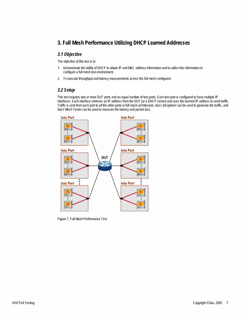
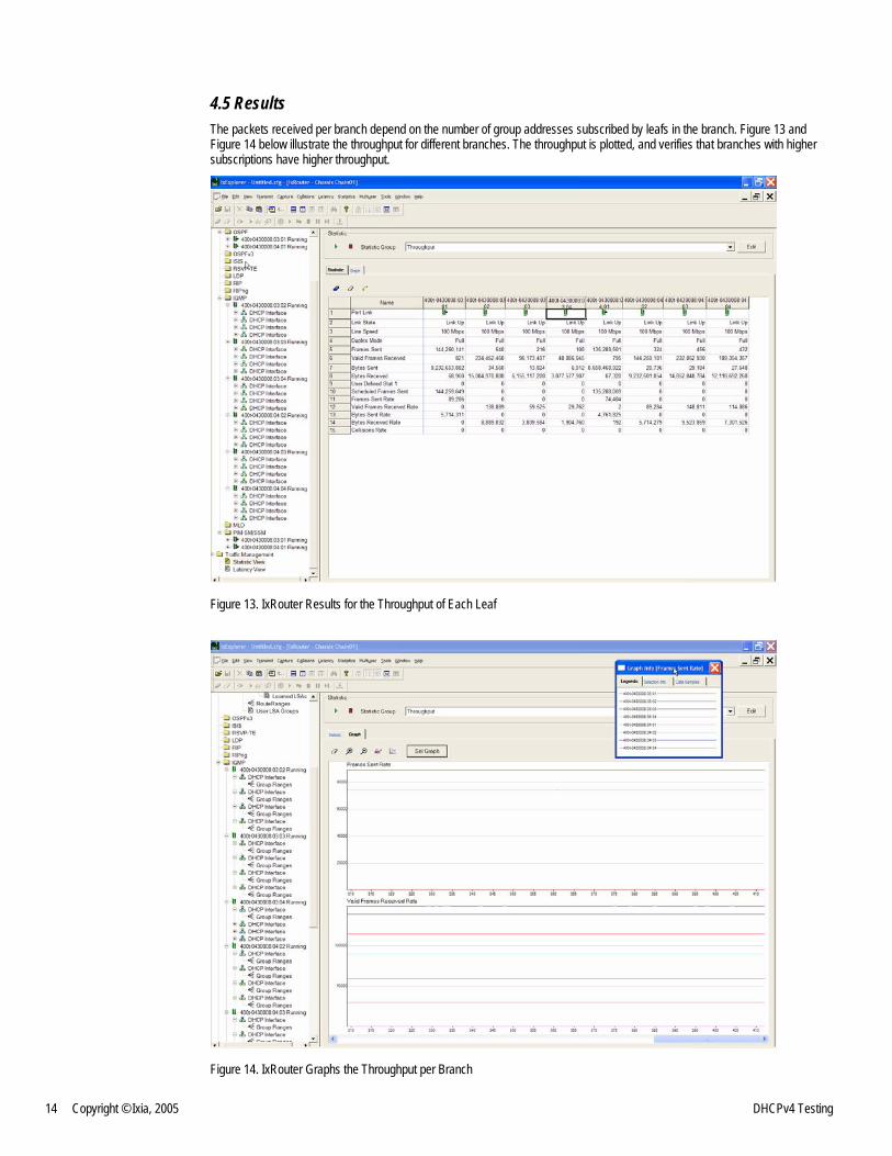
4.5 Results The packets received per branch depend on the number of group addresses subscribed by leafs in the branch. Figure 13 and Figure 14 below illustrate the throughput for different branches. The throughput is plotted, and verifies that branches with higher subscriptions have higher throughput.
Figure 13. IxRouter Results for the Throughput of Each Leaf
Figure 14. IxRouter Graphs the Throughput per Branch
DHCPv4 Testing Copyright © Ixia, 2005 15
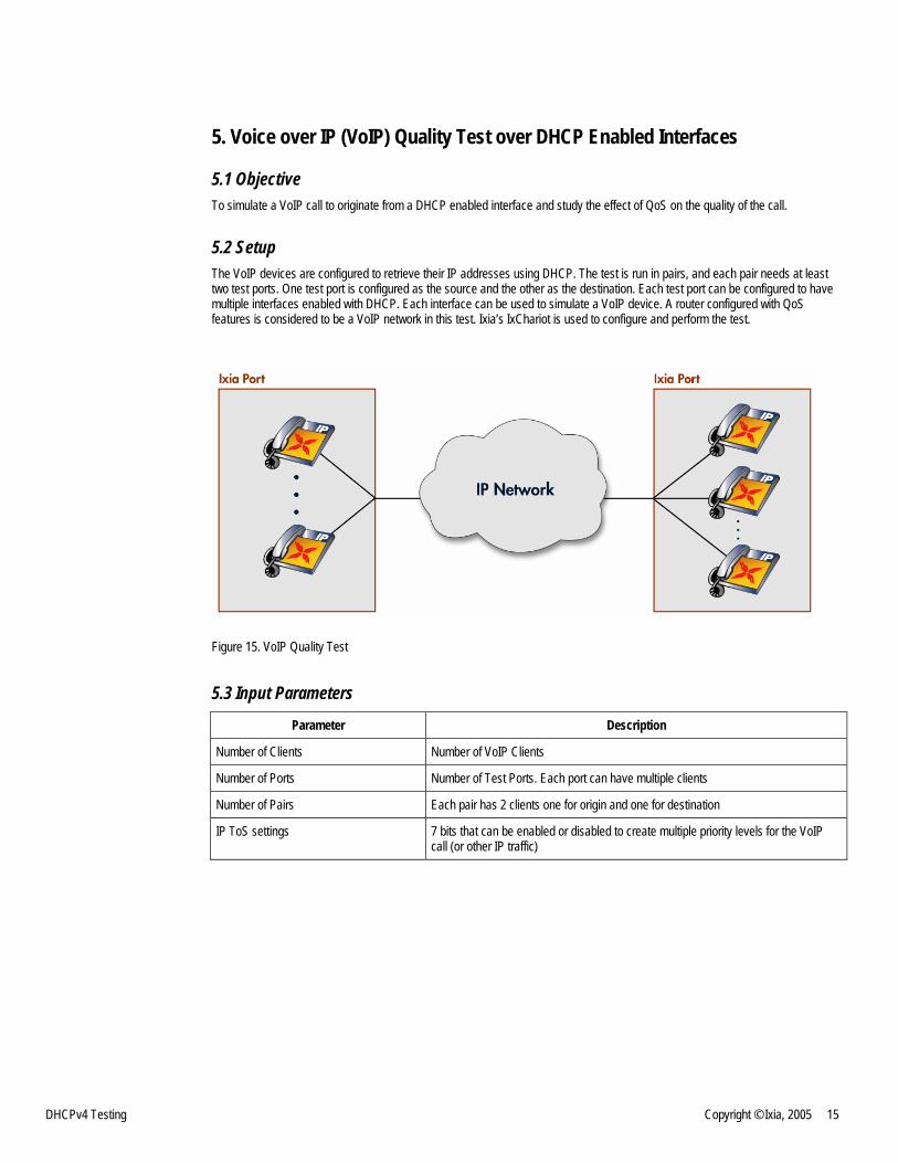
5. Voice over IP (VoIP) Quality Test over DHCP Enabled Interfaces
5.1 Objective To simulate a VoIP call to originate from a DHCP enabled interface and study the effect of QoS on the quality of the call.
5.2 Setup The VoIP devices are configured to retrieve their IP addresses using DHCP. The test is run in pairs, and each pair needs at least two test ports. One test port is configured as the source and the other as the destination. Each test port can be configured to have multiple interfaces enabled with DHCP. Each interface can be used to simulate a VoIP device. A router configured with QoS features is considered to be a VoIP network in this test. Ixia’s IxChariot is used to configure and perform the test.
Figure 15. VoIP Quality Test
5.3 Input Parameters
Parameter Description
Number of Clients Number of VoIP Clients
Number of Ports Number of Test Ports. Each port can have multiple clients
Number of Pairs Each pair has 2 clients one for origin and one for destination
IP ToS settings 7 bits that can be enabled or disabled to create multiple priority levels for the VoIP call (or other IP traffic)

16 Copyright © Ixia, 2005 DHCPv4 Testing
5.4 Methodology 1. Configure the Test Ports to have at least one client per port.
2. Setup the DUT to route traffic using DSCP or IP ToS precedence.
3. Set up back ground traffic to be more representative of a real-world scenario.
4. Download agents to the interfaces to enable TCP/IP hand shaking.
5. Configure multiple pairs with different IP ToS settings.
6. Run VoIP simulated traffic and measure MOS score and throughput.
7. Enable traffic policing on the DUT during the test to see the difference in the MOS scores and throughput.
5.5 Results Figure 16 shows the MOS estimate for the VoIP pairs with different QoS parameters.
The sudden jump in the MOS estimate for some of the pairs occurred when traffic policing was enabled on the DUT. It can be seen that for the pairs with higher priority, the MOS estimate increased significantly; and for the pairs with lower priority, the MOS estimate remained low.
Figure 16. IxChariot Window Showing MOS Estimates Change When QoS Is Turned On

DHCPv4 Testing Copyright © Ixia, 2005 17
Figure 17 shows the throughput for the same pairs. The throughput can be seen to be the same for all the VoIP pairs initially; but when traffic policing is turned on, the difference in throughput for the different pairs becomes apparent.
Figure 17. IxChariot Window Showing Throughput Vary with QoS


![[MS-DHCPF]: DHCP Failover Protocol Extension... · 2018-09-11 · failover relationship: An association between two DHCPv4 servers, for example, a primary server and a secondary server,](https://img.dokumen.tips/doc/110x75/5f7da9d3dff8ba5c6764b9ef/ms-dhcpf-dhcp-failover-protocol-extension-2018-09-11-failover-relationship.jpg)