Embed Size (px)
Citation preview

PERFORMANCE ANALYSIS OF DIRECT COMMUNICATION SCHEMEIN TACTICAL RADIO ACCESS NETWORKS BASED ON UMTS1
Jong-Wuk Son, Hye-jeong Lee, Woon-Young Yeo andDong-Ho Cho
KAIST, Daejeon, Republic of Korea{jwson, hjlee, wyyeo, and dhchoJ} @comis.kaist.ac.kr
ABSTRACT
In fast moving combat situations, the role of militarywireless network is emphasized significantly. Over lastdecade, the civilian mobile communication technology hasproceeded at an unprecedented pace. The advantages ofcivilian mobile communication technology, such as largecapacity and reliable transmission, are attractive to thetactical communication network designers. As a result, lotsof researches to apply the advantages of the civilian com-munications technology and architecture to designing thetactical communication systems have been investigated.Especially, the adaptation ofthe Radio Network Subsystem(RNS) framework of Universal Mobile Tele-communication System (UMTS) for the tactical wirelesscommunication system has been investigated. In this paper,we propose a new direct communication scheme in tacticalradio access networks based on UMTS. The simulationresults show the feasible performance when the directcommunication scheme is applied in tactical radio accessnetworks based on UMTS.
I. INTRODUCTION
The future tactical communication system must be ableto transport the enormous amounts of information quicklyand reliably. However, in the aspect of cost invested inResearch and Development (R & D), it is inefficient todevelop an independent and individual tactical communi-cation system. On the other hand, the civilian radio accessnetwork technology has proceeded at an unprecedentedpace over last decade. As a result, the civilian communica-tion systems outperform the conventional tactical commu-nication systems in view of system capacity, data trans-mission rates, reliability and system development speed.Accordingly, lots of researches to apply the civilian tech-nology and architecture to designing the tactical communi-cation systems have been investigated. By utilizing thecivilian communication technology, the tactical communi-cation system can take the advantages of it such as highcapacity, high data transmission rates and reliability.
1 This work has been performed as the experimental project of theADD (Agency for Defense Development) which is studying future tac-tical communication network architecture.
andGui-Soon Park
ADD, Daejeon, Republic of Koreagparkoadd.re.kr
In [1 ] [2], architectural concept for tactical radio accessnetwork based on UMTS is proposed, which is called atactical radio access network (TRAN). According to [2],by adapting RNS framework of UMTS for the tacticalwireless communication system, the TRAN can deal withthe different types of command and control structures. Inaddition, the TRAN can support communication betweencommunication units in radio access network where corenetwork is not available due to the failure of the core net-work or attack in the core network. Although TRAN sys-tem based on UMTS is efficient to take the advantages ofcivilian UMTS systems, it doesn't support direct commu-nication between network nodes in case there is no infra-structure. In this paper, we propose a new direct communi-cation scheme in tactical radio access networks based onUMTS. The paper is organized as follows. The require-ments of direct communication are described in Section II.In Section III, the technical description of direction com-munication scheme is given in detail and the simulationresults are shown in Section IV. Finally, conclusions andfurther works are addressed in Section V.
II. REQUIREMENTS
In wartime, the combat can occur in every area. Even ifall infrastructures are destroyed or not available, commu-nication between commander and combatant or betweencombatants should be supported. If direct communicationof the tactical mobile stations (T-MS) is possible, the com-bat efficiency will be enhanced. In case that the T-MSs arenot in the coverage of tactical BTS, they can communicateeach other by using direct communication scheme. More-over, T-MSs are placed in the coverage of tactical BaseTransceiver Station (BTS), the traffic load of tactical BTScan be distributed by the direct communication scheme. Inorder to support direct communication, the T-MS mustoperate on the dual mode; one is the cellular mode and theother is the direct communication mode (DCM). In DCM,the T-MS should support not only point-to-point commu-nication but also broadcast and multicast communications.In addition, the T-MS must support several service classeswhich include not only real-time traffic such as voice ser-vice, but also non-real-time traffic such as the backgroundtraffic. Basically, the physical channel and code used for
1 of 6

the direct communication can be made by modifying thoseused for UMTS FDD.
III. DIRECT COMMUNICATION SCHEME
In this section, we describe a proposed direct communica-tion scheme in detail. We assume that the frequency forDCM is allocated newly, which is different from that forUMTS so it is not interfered by the frequency used inUMTS. Throughout the paper, the T-MS to initiate a call isnamed Master, and the T-MS to accept the call is namedSlave. To communicate between two T-MSs in the areawhere no tactical BTS is available, Master should takesome roles instead of BTS. The main role to be performedby Master is the signal transmission for synchronization.
A. SYNCHRONIZATION
In UMTS, Synchronization Channel (SCH) is a downlinksignaling channel used for cell search, which consists oftwo sub channels, the Primary and Secondary SCH [3].The cell search procedure in UMTS is described in [5]. Toseparate a Node-B from the neighboring Node-Bs, total512 downlink scrambling codes are used. The scramblingcodes are subdivided into 64 groups and each subgroupincludes eight codes. In DCM, we use only 4 scramblingcodes to separate Master from other Masters in theneighborhood. By doing so, the delay to find frame syn-chronization and to identify scrambling code will be re-duced. Secondary Synchronization Codes (SSCs) for Mas-ter in DCM are the same codes with Node-Bs in UMTS.However, Master uses only 4 SSCs because only 4 scram-bling codes are used in DCM.
The procedure that Master selects 1 SSC among 4 SSCsas its synchronization codes is performed according to thefollowing two steps.
1) Step 1: Master searching process
All T-MSs which operate on DCM periodically checkwhether there is a request to set up a call or not. From thisprocedure, all T-MSs would know not only which SSCsare being used by other Masters but also whether the callfor itself is requested or not.
2) Step 2: SSC selection process
From the first step, Master can know which SSCs areused by other Masters in the neighborhood. ThereforeMaster can select 1 SSC which is not being used by otherMasters. If all 4 SSCs are already used for call request byother Masters, new call request must be suspended.
The procedure that Slave acquires the synchronizationand scrambling code identification consists of the follow-ing two steps.
1) Step 1: Slot synchronization
Basically, the procedure for Slave to find slot synchro-nization in DCM is similar to that for user equipment(UE) in UMTS. The procedure for UE to find slot syn-chronization is described in [5]. The difference of the op-erations between UE and Slave is that Slave should seekall peaks detected for the primary synchronization code(PSC) because other Masters can be located closer thanits own Master.
2) Step 2: Frame synchronization and scrambling codeidentification
To find the frame synchronization and to seek thescrambling codes which are used by Master, Slave usesthe SSCs. These procedures are enabled by correlatingthe received signal with all possible SSC sequences andidentifying the maximum correlation value [4]. Since thecyclic shifts of the sequences are unique, scrambling codeidentification as well as the frame synchronization can bedetermined. After scrambling code has been identified,Slave can detect the paging destined to it and the call canbe connected. For paging, Master uses Primary CommonControl Physical Channel (P-CCPCH) of UMTS. P-CCPCH includes the identification of Slave (or groupidentification), class of traffic and code information. Asthe identification of Slave, International Mobile Sub-scriber Identity (IMSI) can be used. The group identifica-tion is used in case of multicasting or group communica-tion. Group Mobile Subscriber Identity (GMSI) is used asthe group identification. The T-MSs of a group have thesame GMSI. GMSI can be allocated in advance or modi-fied by user. The class of traffic indicates whether the callis for voice or data. The code information consists ofscrambling code identifications and spreading code iden-tifications. The scrambling code identifications indicatewhich scrambling codes are used by Master and Slaveduring the data transmission. After the call is connected,Master and Slave can receive and transmit data by usingscrambling code which is indicated by Master. The ca-pacity can be increased by separating scrambling codesinto two parts; one for call setup request and the other fortransferring data. The spreading code identifications indi-cate which channelisation codes are used by Master andSlave.
B. CALL SETUP PROCEDURE
In this section, we provide the signaling procedure forcall setup in DCM. Fig. 1 shows the call flow for call setup.The detail procedures are as follows.
2 of 6
| ime synch bhization, scrarnbihng bodb ihf'bP6ghaPCHP bPCCH
[UJE ID, type bf trAllffit, Odle lhformhtioh]
Paging Respbhgd (CCCH/IRACHd/P0HACHi)[WE !1]
Connection Release (DCGH/bDH/DCOCH)
Conniection Release compbI6f6(DCCH/DCH/lD0lC
Figure 1. Call flow for direct communication
1) Paging
Master transmits the paging signal with synchronizationsignal several times. The paging information is sent via P-CCPCH. P-CCPCH includes the ID (IMSI) of the destinedT-MS, class of traffic and scrambling code identificationswhich is used after call connection.
2) Paging response
If Slave detects the paging from Master, Slave prepares toreceive and transmit data according to the received infor-mation such as class of traffic and code information. Aftercompleting the preparation for receiving, Slave transmitspaging response message to Master. Paging response issent through Random Access Channel (RACH).
3) Data transmission
For the data transmission, the modified Dedicated Chan-nel (DCH) is used by Master and Slave. In UMTS, the up-link DPCCH uses a slot structure with 15 slots over the 10ms radio frame. Each slot has four fields which are pilotbits, TFCI bits, Transmission Power Control (TPC) bitsand Feedback Information bits (FBI) respectively [5].However, because FBI is not necessary in DCM, the FBIfield is excluded in DCM. As a result, the slot in DCMconsists of pilot bits, TFCI bits and TPC bits.
4) Connection release and Connection release complete
If a user terminates the call, Master or Slave transmits theconnection release message to the destined T-MS. Afterreceiving the connection release message from Master orSlave, the T-MS changes its state to idle state and trans-
mits the connection release complete message to Master orSlave. After connection release, Master and Slave performMaster searching process and check periodically whetherthere is a request for a call setup or not.
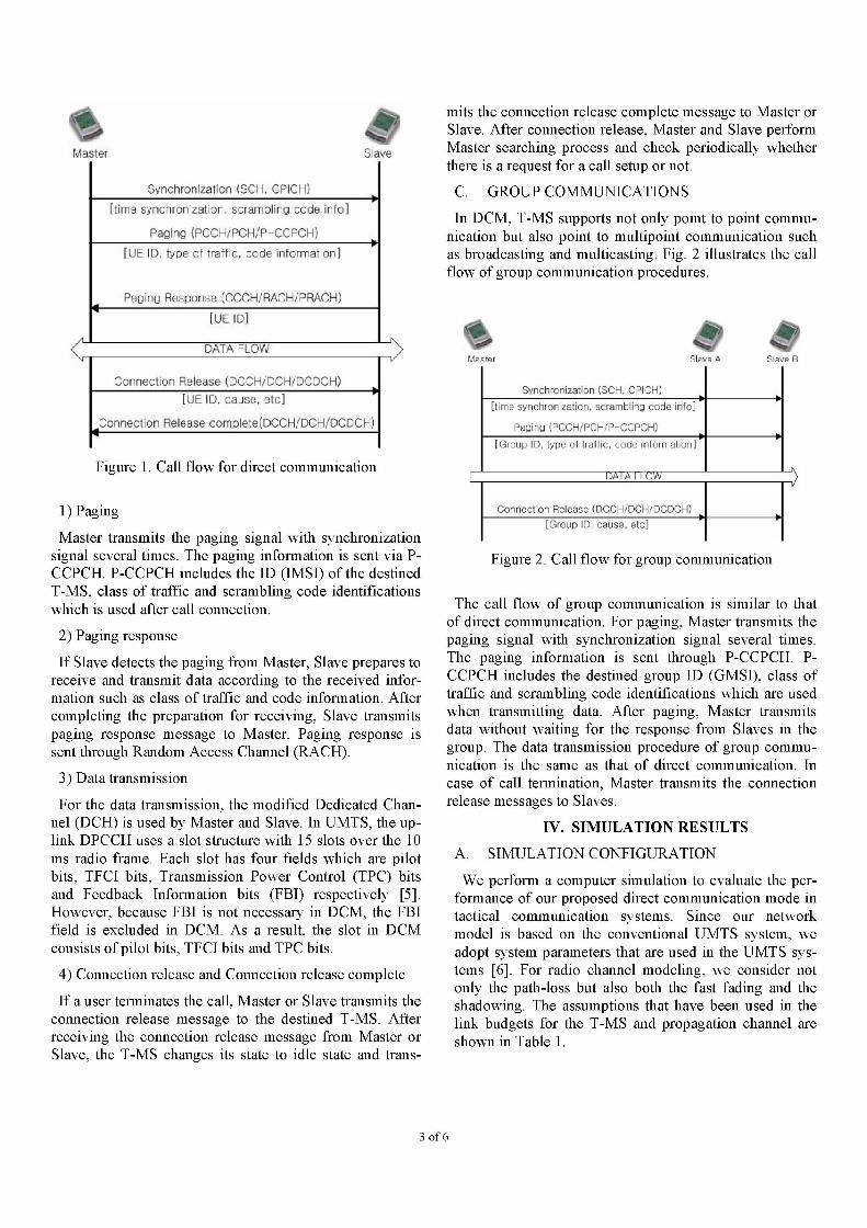
C. GROUP COMMUNICATIONS
In DCM, T-MS supports not only point to point commu-nication but also point to multipoint communication suchas broadcasting and multicasting. Fig. 2 illustrates the callflow of group communication procedures.
Synch rcniZatioh (SCH, QPI GH)
Peidlo (POCHYPOH/P-ccPCH)e c trdffic. £o ihfbrnatOn]
DATA FLOW .
C hdctih Re1Asb (DCCH/DCHCClHiO ID, causO. 1tC
Figure 2. Call flow for group communication
The call flow of group communication is similar to thatof direct communication. For paging, Master transmits thepaging signal with synchronization signal several times.The paging information is sent through P-CCPCH. P-CCPCH includes the destined group ID (GMSI), class oftraffic and scrambling code identifications which are usedwhen transmitting data. After paging, Master transmitsdata without waiting for the response from Slaves in thegroup. The data transmission procedure of group commu-nication is the same as that of direct communication. Incase of call termination, Master transmits the connectionrelease messages to Slaves.
IV. SIMULATION RESULTS
A. SIMULATION CONFIGURATION
We perform a computer simulation to evaluate the per-formance of our proposed direct communication mode intactical communication systems. Since our networkmodel is based on the conventional UMTS system, weadopt system parameters that are used in the UMTS sys-tems [6]. For radio channel modeling, we consider notonly the path-loss but also both the fast fading and theshadowing. The assumptions that have been used in thelink budgets for the T-MS and propagation channel areshown in Table 1.
3 of 6
L_-.\It.-
r Ii

Table 1. Assumption for simulation
T-MSService type 12.2 kbps speech
Maximum tx power 25 dBmBody loss 3 dB
Antenna gain 0 dBiNoise figure 6 dB
ChannelStandard deviation 6.5 dBof slow fading
Fast fading model Jake's model
The maximum transmission power of T-MS is set as 25dBm and the minimum transmission power is set as -50dBm. Although the maximum transmission power of UEis limited as 21 dBm in [6], we set the maximum trans-mission power of T-MS as 25 dBm by considering thecharacteristic of military communication equipments. Thelink budget for 12.2 kbps voice call for pedestrian users iscalculated in Table 2.
Table 2. Link budget of 12.2 kbps voice service
TransmitterMax. MS tx power [dBm] | 25 aMS antenna gain [dBi] 0 bBody loss [dB] 3 cEquivalent Isotropic Radiated 22 dPower (EIRP) [dBm] 2 a+b-c
ReceiverThermal noise density [dBm/Hz] -174 eMS receiver noise figure [dB] 6 fReceiver noise density -168 g[dBm/Hz] = e + f
h=
Receiver noise power [dBm] -102.1 og1O(3840000)
Interference margin [dB] 2.0 iNoise + interference [dBm] -100.1 j = h + iProcessing gain [dB] 25.0 kRequired Eb/N0 [dB] 5.0 1
mReceiver sensitivity [dBm] -120.1 = I -k+jFast fading margin [dB] 2.0 n
Max. path loss [dB] 140.0 d-m-p
Log-normal fading margin [dB] 4.2 PAllowed path loss [dB] 135.8 r = o - p
From the link budgets, the maximum distance betweentwo communicating T-MSs can be calculated. For propa-gation model, Okumura-Hata loss model is used in thissimulation. For suburban area, we assume the path loss(L) as [8]
L = 129.4 + 35.2*loglO(R), (1)
where R is the distance in kilo-meters. According toEquation (1), the maximum distance between two com-municating T-MSs of 12.2 kbps speech service with135.8 dB path loss would be 1.5 Km. T-MSs are ran-domly distributed in simulation area (10 X 10 kM2) andthe distance between two communicating T-MSs is lim-ited to 1.5 km. The simulation is performed for two cases;one uses the power control and the other does not use thepower control. In case that power control is used, thetransmission power is updated at each time slot. If the re-ceived SINR is smaller than the target SINR, the Trans-mit Power Control (TPC) command requests T-MS to in-crease its transmission power, else request T-MS todecrease its transmission power. Power control step is 1dB and the target SINR, F tar is fixed as 5 dB. If thepower control is not used, the transmission power of T-MS is fixed as the maximum transmission power, 25dBm. An activity factor for speech is set as 0.67. Callgeneration and termination are modeled by a birth-deathPoisson process assuming the mean call duration of 120seconds [7]. Performance is evaluated in view of callblocking rate, call dropping rate and bit error rate (BER).A new call is admitted, if all ongoing calls can maintainacceptable SINR after the new call is accepted where ac-ceptable SINR, F acc is 4.5 dB. The call blocking rate isthe ratio of the number of mobiles whose call are not ac-cepted to the number of total mobiles. An ongoing callmay be dropped, when the mean SINR of the user duringa call remains below threshold SINR for 1 second, wherethreshold SINR, F thr is 4 dB.
B. SIMULATION RESULTS
Figures 3, 4, and 5 show the simulation results, in view ofthe call blocking probability, call dropping probability andbit error rate, respectively. From Figures 3 and 4, we canobserve that the power control can enhance the system per-formance. In view of both the call blocking probability andcall dropping probability, power control is efficient to en-hance the performance of the tactical communication sys-tem without regard to the change of offered load. Howeverthe power control in this system adopts not a centralizedmechanism but a distributed mechanism, therefore some-times the power control may give rise to a negative effecton the performance. Figure 5 shows the bit error rate ac-cording as the offered load increases. We can see that thebit error rate when power control is applied is higher than
4 of 6
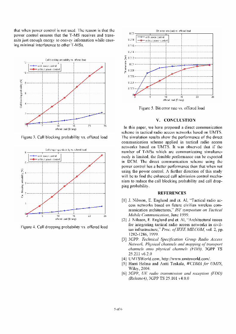
that when power control is not used. The reason is that thepower control ensures that the T-MS receives and trans-mits just enough energy to convey information while caus-ing minimal interference to other T-MSs.
Call blocking probability vs. offered load
111 1 5offered load (Erlang)
Figure 3. Call blocking probability vs. offered load
Call dropping probability vs. offered load
5 1 0 1 5 20offered load (Erlang)
Figure 4. Call dropping probability vs. offered load
-L-m 0.(cs.-2.2 0
8a)
:= 0.(m
Bit error rate (ber) vs. offered load
5 160 15 20offered load (Erlang)
Figure 5. Bit error rate vs. offered load
V. CONCLUSTION
In this paper, we have proposed a direct communicationscheme in tactical radio access networks based on UMTS.The simulation results show the performance of the directcommunication scheme applied in tactical radio accessnetworks based on UMTS. It was observed that if thenumber of T-MSs which are communicating simultane-ously is limited, the feasible performance can be expectedin DCM. The direct communication scheme using thepower control has a better performance than that when notusing the power control. A further direction of this studywill be to find the enhanced call admission control mecha-nism to reduce the call blocking probability and call drop-ping probability.
REFERENCES
[1] J. Nilsson, B. Englund and et. Al, "Tactical radio ac-cess networks based on future civilian wireless com-munication architectures," IST symposium on TacticalMobile Communication, June 1999.
[2] J. Nilsson, B. Englund and et. Al, "Architectural issuesfor integrating tactical radio access networks in civil-ian infrastructure," Proc. ofIEEE MILCOM, vol. 2, pp.1282-1286, 1999.
[3] 3GPP. Technical Specification Group Radio AccessNetwork. Physical channels and mapping of transportchannels onto physical channels (FDD). 3GPP TS25.211 v6.2.0
[4] UMTSWorld.com, http://www.umtsworld.com/.[5] Harri Holma and Antti Toskala, WCDMA for UMTS,
Wiley, 2004.[6] 3GPP, UE radio transmission and reception (FDD)
(Release4), 3GPP TS 25.101 v4.0.0
5 of 6
with power controlwthout power contori
with power control-without power contorl
;,'40-00-0.;3zmC.!M-M-2
0-020
V
h
n,i6

[7] 3GPP, UMTS; Selection procedures for the choice ofradio transmission technologies of the UMTS, TR 101112 v3.2.0 (1998-04)
[8] 3GPP, Spatial channel model for Multiple Input Mul-tiple Output (MIMO) simulations, TR25.996 v6. 1.0(2003-09)
6 of 6


![Untitled-1 [] · cm dell da- bk chip del 8k no chip oel hy chip del man-ex bk8y del da wmbkchlpl-m chp part no. pxr-tfc115b pxr-tfcios m.tfc1tn8Žp pxr-tfc1tnb pxr-tfci 17b pxr-tfci](https://img.dokumen.tips/doc/110x75/60390b9ed017f17e78385547/untitled-1-cm-dell-da-bk-chip-del-8k-no-chip-oel-hy-chip-del-man-ex-bk8y-del.jpg)