Embed Size (px)
Citation preview

DHANALAKSHMI COLLEGE OF ENGINNEERING, CHENNAI
DEPARTMENT OF MECHANICAL ENGINEERING
ME 6401- KINEMATICS OF MACHINERY
UNIT - I : BASICS OF MECHANISM
PART – A (2 Marks)
1. Differentiate between Machine and Mechanism.
2. Define - Link and List the various type of link
Link is a resistant body is one which is capable of transmitting the required motion and force with negligible deformation in the direction of force transmission. Types of links: 1) Rigid Link 2) Flexible link 3) Fluid link
3. Define - Kinematic Chain Kinematic chain is defined as the combination of kinematic pairs in which each link forms a pair of two kinematic pairs and the relative motion between the links is either completely constrained or successfully constrained. When a number of links connected in space make relative motion of any point on a link with respect to any other point on the other link follow a definite law it is known as kinematic chain.
4. Define - Kinematic Pair When two links are in contact with each other it is known as a pair. If the pair makes constrain motion it is known as kinematic pair.
5. Classify the kinematic pair based on the various characteristics. Kinematic pairs are classified on the basis of the following characteristics 1) Type of relative motion between contacting elements 2) Type of contact between contacting elements 3) Type of closure
6. Define - Lower Pair and Higher Pair Kinematic pairs in which there is a surface (area) contact between the contacting elements. All revolute pairs, sliding pairs, screw pairs, globular pairs, cylindrical pairs and flat pairs are Lower Pairs. Kinematic pairs in which there is a point or line contact between the contacting elements are called as higher pair. Meshing gear teeth, cam and follower pair, wheel rolling on a surface, a ball and roller bearings and pawl and ratchet are higher pair.
Machine Mechanism
Machine is a mechanism or collection of mechanism which transmits force from the source of power to the resistance (load) to overcome and thus performs useful mechanical work.
Combination of rigid or resistant bodies connected that they move upon each other with definite relative motion,
Eg. Lather, Shaping Machine etc. Eg. Single slider mechanism
All machines are mechanism All mechanism are not machine

7. Differentiate between machine and structure.
8. Classify Constrained Motion (or) Write short notes on complete & incomplete constraints in lower & higher pair
When the motion of a kinematic link/pair is restricted to a particular direction/path, it is called
constrained motion. It can be classified as: i) Completely constrained motion: If the movement of the link is restricted to move in one particular path only, it is completely constrained. ii)Incompletely constrained motion: If the movement of the link is restricted to move in more than one path, it is incompletely constrained motion. iii)Successfully constrained motion: If the movement of the link is restricted to one particular path and made it to stop at particular length of the movement it is successfully constrained motion
9. Define - Degree of Freedom (or) Mobility and give the DOF for a shaft in a circular hole. It is defined as the minimum number of input parameters which must be independently controlled, in-order to bring the mechanism into a useful engineering purpose. DOF for a shaft in circular hole is 2. It will have sliding motion and rotational motion. If the shaft end is fixed to a collar, sliding motion will be arrested and DOF is 1.
10. Write down Kutzbach criterion to find the mobility of a planar mechanism. The Kutzbach criteria which calculates the mobility n = 3(L-1) - 2j - h Where, n- Degrees of freedom L – number of links j – number of joints h – no of higher pairs
11. Determine the number of degrees of freedom of the mechanism shown in the figure below.
No of links l = 10
No of joints j = 9
Machine Structure
Machine is a mechanism or collection of mechanism which transmits force from the source of power to the resistance (load) to overcome and thus performs useful mechanical work.
Structure is the assemblage of resistant bodies without any relative motion between the links.
Eg. I C Engine Eg. Bridges & Dams

The joints formed in closed loop (at link 2) will be considered as one joint. [Eg Joints at (1,2), (9,2) & (3,2) forms a joint]. Deg of freedom n = 3(L-1) - 2j - h Since h=0 (no higher pair), n = 3 (10-1) – 2(9) = 9 Degrees of freedom n = 9 12. Write down the Grubler’s criteria for planar mechanism. The following equation is used to describe mobility in 2D or planar systems:
M = 3(N-1) – 2 f1 – f2 N = total number of links M = DOF f1 = number of 1 DOF joints f2 = number of 2 DOF joints
This is known as Grubler’s equation and is for mobility of planar systems.
13. State Grashof’s law for a four bar linkage. It states that for a planar four bar linkage, sum of the shortest and longest link – lengths must be less than or equal to the sum of the remaining two link-lengths, is there is to be a continuous relative motion between two members, S + L ≤ P + Q ; Where, S – length of shortest link, L – length of longest link, P and Q – remaining two link lengths. i) If L + S < P + Q, then we call this a Grashof’s mechanism
G.1 = crank-rocker mechanism if S is the crank and either of the adjacent link is the fixed link G.2 = double-crank mechanism if S is the fixed link G.3 = double-rocker mechanism if the link opposite S is the fixed link
ii) If L + S > P + Q, then we call it non-Grashof’s mechanism only double-rocker: no link is capable of making a complete revolution
14. Define - Kinematic Inversion A mechanism is formed by fixing one of the links of a chain. The process of choosing different links of a kinematic chain for making different kind of mechanism is called Kinematic Inversion.
15. Name the inversions of four bar mechanisms. First Inversion – Coupled wheels of locomotive – double crank, Second Inversion – Beam Engine - Crank and lever mechanism, Third Inversion – Watt’s Engine Indicator – Double lever mechanism.
16. Name the inversions of single slider mechanism. First Inversion – Reciprocating engine mechanism, Second Inversion – Gnome Engine or Rotary Engine – Whitworth quick return mechanism, Third Inversion – Quick return mechanism – Crank and slotted lever – Oscillating cylinder engine, Fourth Inversion – Hand Pump.
17. List out the inversions of a double slider crank chain. First Inversion – Scotch Yoke mechanism, Second Inversion – Oldham’s Coupling, Third Inversion – Elliptical trammel.

18. Name some straight line generating mechanism. Straight line generating Mechanism – Peaucellier mechanism, Scott Russel mechanism and Hart’s mechanism, Robert’s Mechanism and Tchibicheff Mechanism.
19. Define - Transmission Angle In a four bar chain mechanism the angle between the coupler and the follower link is called as the transmission angle.
Therefore, angle BCD is called transmission angle. When the transmission angle deviates significantly from /2, the torque on the output bar decreases and may not be sufficient to overcome the friction in the system. For this reason, the deviation angle
=| /2- | should not be too great. In practice, there is no definite upper limit for , because the existence of the inertia forces may eliminate the undesirable force relationships that is present under
static conditions. Nevertheless, the following criterion can be followed. 20. Define - Mechanical Advantage
It is defined as the ratio of the output force or torque, supplied by the driven link, to the input force or torque, required to be supplied to the driver link.
21. Differentiate between rigid and resistant bodies A rigid body is an idealization of a solid body in which deformation is neglected. In other words, the distance between any two given points of a rigid body remains constant in time regardless of external forces exerted on it. A body is said to be a resistant body, if it does not deform for the purpose for which it is made. For example the chair, it does not deform if a person sits on it, but it will break if you put a load of 1000 kg on it. So a resistant body is rigid for the purpose for which it is used.
22. What is meant by spatial mechanism? If there is any relative motion that is not in the same plane or in parallel planes, the mechanism is called spatial mechanism. Spatial mechanisms are three dimensional.
23. Define - Sliding Connectors When the two elements of a pair are connected in such a way that one can only slide relative to the other, then the connector is called Sliding connector. The piston and cylinder, cross-head and guides of a reciprocating steam engine, ram and its guides in shaper, tail stock on the lathe bed are examples of Sliding Connectors.
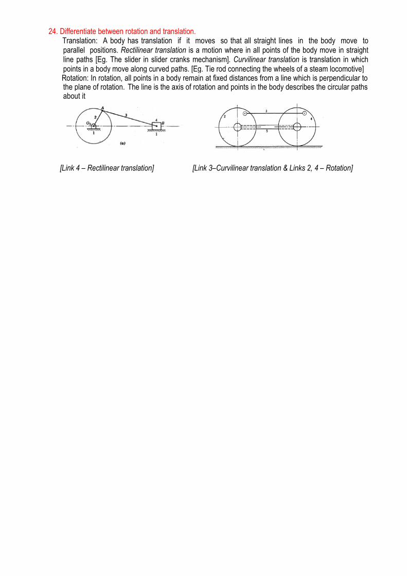
24. Differentiate between rotation and translation. Translation: A body has translation if it moves so that all straight lines in the body move to
parallel positions. Rectilinear translation is a motion where in all points of the body move in straight line paths [Eg. The slider in slider cranks mechanism]. Curvilinear translation is translation in which points in a body move along curved paths. [Eg. Tie rod connecting the wheels of a steam locomotive]
Rotation: In rotation, all points in a body remain at fixed distances from a line which is perpendicular to the plane of rotation. The line is the axis of rotation and points in the body describes the circular paths about it
[Link 4 – Rectilinear translation] [Link 3–Curvilinear translation & Links 2, 4 – Rotation]

PART – B (16 Marks)
1. Define inversion of mechanism. Explain the inversions of four bar mechanism with neat sketch with
suitable example. (or) Sketch & explain any three kinematic inversion of 4 bar chain. [June 2014]
2. Explain the various inversions of double slider crank mechanism with neat sketch.
3. Describe Whitworth's quick return mechanism with neat sketch.
4. i) Explain the various inversions of single slider crank mechanism with neat sketches.
ii) Determine the degrees of freedom (Fig 1) for the following linkages [Nov 2013]
5. State and prove Kutzbach criterion for the following kinematic chains: Three bar chain, Four bar chain,
Cam with knife edge follower.
6. Sketch and explain any various types of straight-line motion generating mechanism.

UNIT – II : KINEMATIC ANALYSIS
PART – A (2 Marks)
1. How will you determine the direction of Coriolis component of acceleration? The direction of coriolis component of acceleration can be determined by rotating the velocity of sliding
vector vs through 90˚ in the direction of rotating angular velocity. 2. Explain normal component of acceleration. The acceleration of a particle at any instant moving along a circular path in a direction normal to the tangent at that instant and directed towards the centre of circular path [direction from A to O] is called normal component of acceleration or normal acceleration. It is also called as radial or centripetal acceleration.
3. Define - Rubbing Velocity The links in a mechanism are mostly connected by means of pin joints. The rubbing velocity (Vr) is defined as the algebraic sum between the angular velocities (ω) of the two links which are connected by pin joints, multiplied by the radius(r) of the pin. Vr = ωr.
4. Define - Coriolis Component of Acceleration When a point on one link is sliding along another rotating link, such as in quick return motion mechanism, then the coriolis component of the acceleration must be calculated to determine the direction of acceleration component. It can be calculated by:
5. What is meant by Virtual Centre? The combined motion of rotation and translation of the link may be assumed to be a motion of pure rotation about some centre I, known as the Instantaneous Centre of rotation also called as centro or virtual centre
6. Illustrate the space centrode and body centrode. The locus of the instantaneous centre in space during a definite motion of the body is called as space centrode. The locus of the instantaneous centre relative to the body itself is called as body centrode.

7. Name any two mechanisms having coriolis component. Crank and Slotted lever quick return mechanism and Whitworth quick return mechanism.
8. How will you determine the total acceleration of a point on a link, when the normal component of acceleration and the tangential component of acceleration are known? The total acceleration of a point on the link is the summation of tangential component of acceleration [Ft] and normal component of acceleration [Fn]. Ftot = Fn+Ft
9. State the properties of instantaneous centre method. An Instantaneous centre of rotation is a point common to two links having relative motion. IC is a point about which one body can be assumed to rotate with respect to the other. It is an imaginary point at which the two bodies have same absolute velocity. It follows that the two bodies have zero relative velocity at the coincident points I. IC is in general not a stationary point, because the mechanism moves from one position to another, the velocities of points like A and B keep on changing.
10. State the Kennedy’s theorem. It states that if three bodies are in relative motion with respect to one another, the three relative instantaneous centres of velocity are collinear.
11. List the various types of instantaneous centres. The various types of instantaneous centres are 1. Fixed Instantaneous Centre, 2. Permanent Instantaneous Centre and 3. Neither fixed or permanent Instantaneous Centre
To determine the number of instantaneous centre in a mechanism, the formula used is N(N-1) / 2 where, N –no of links. E.g., For 4 bar mechanism, No of links = 4, No of Instantaneous centre = 6 12. For what type of mechanism Coriolis component of acceleration is taken into account.
The mechanism containing the turning pair and sliding pair in the same point needs to determine coriolis component. Whitworth Quick return mechanism and Crank and slotted level mechanism are examples of such mechanism.
13. What is meant by coincident points? In quick return motion mechanism, like Crank & Slotted lever mechanism and Whitworth quick return
motion mechanism, the end point of the crank and point on the slotted lever are the same point. In crank, it will be turning pair. In Slotted lever, it will be sliding pair. The same point will act as a turning pair and sliding pair in such mechanism. Such type of point is called Coincident points. In coincident point, in one pair, the point will be turning and in another pair it will be sliding.
14. What is meant by instantaneous axis, axode and centrode? A line drawn through an instantaneous centre and perpendicular to the plane of motion. The locus of the instantaneous axis is known as axode. The locus of all instantaneous centres is called as centrode.
15. What is meant by configuration diagram? Where do we use it? The diagram which is drawn with the actual scale at the positions shown in the mechanism. By using it, velocity and acceleration of the links can be calculated for this position.
5

16. Define - Low Degree of Complexity. When a complex mechanism can be rendered simple by a change of input link, it is called mechanism having low degree of complexity. For example in a 6 bar mechanism as shown in figure, If the input link is 2, the velocity at point B cannot be determined from velocity at point A as the radius of path of curvature of B is unknown. But if the input link is changed as link 5 or 6, velocity of point at B can be determined. Hence it is called mechanism having low degree of complexity.
17.. Define - High Degree of Complexity. When a complex mechanism cannot be rendered simple by a change of input link, it is called mechanism having high degree of complexity. In such mechanism, the radii of paths of curvature of two or more transfer points of a floating link are not known.
18. What is the need for finding acceleration of linkage in a mechanism.
Acceleration of linkages are determined to get the output acceleration of the various linkages to utilize the mechanism for suitable application.
Low Degree of complexity

PART – B (16 Marks) 1. The crank of a slider crank mechanism rotates clockwise at a constant speed of 300 rpm. The
crank is 150mm and the connecting rod is 600mm long. Determine 1. Linear velocity and
acceleration of the midpoint of the connecting rod 2. Angular velocity and angular acceleration of
the connecting rod at a crank angle of 450 from inner dead centre position.
2. An engine mechanism is shown, the crank CB=100mm, connecting rod BA=300mm with centre of
gravity G, 100mm from B. in the position shown, the crank shaft has a speed of 75 rad/sec and an
angular acceleration of 1200 rad/s2. Fine. 1. Velocity of G and angular velocity of AB and 2.
Acceleration of G and angular acceleration of AB.
3. PQRS is a four bar chain with link PS fixed. The length of the links are PQ=62.5mm, QR=175mm,
RS=112.5mm and PS=200mm. The crank PQ rotates at 10 rad/s clockwise. Draw the velocity and
acceleration diagram when angle QPS=600 and Q and R lie on the same side of PS. Find the
angular velocity and angular acceleration of links QR and RS.
4. In the Toggle mechanism as shown, the slide D is constrained to move on a horizontal path. The
crank OA is rotating in the CCW at a speed of 180 rpm. Increasing at the rate of 50 rad/s2. The
dimensions of the various links are as follows:
OA=180mm, CB=240mm, AB=360mm, and BD=540mm. for the given configuration find.
1. Velocity of slider D and angular velocity of BD and 2.acceleration of slider D and angular
acceleration of BD.
5. The mechanism of a warping machine as shown has the following dimensions.
O1A=100mm, AC=700mm, BC=200mm, BD= 150mm, O2D=200mm, O2E=400mm and
O3C=200mm. The crank rotates at a uniform speed of 100 rad/s. for the configuration determine. 1.
Linear velocity of the point E on the bell crank lever 2. Acceleration of the points E and B and 3.
Angular acceleration of the bell crank lever.
6. The driving crank AB of the quick return mechanism as shown revolves at a uniform speed 200
rpm. Find the velocity and acceleration of the tool box-R, in the position shown, when the crank
makes an angle of 600 with the vertical line of centres PA. What is the acceleration of sliding of the
block at B along the slotted lever PQ?

UNIT – III : KINEMATICS OF CAMS
PART – A (2 Marks)
1. Define - Cam A cam may be defined as a machine element having a curved outline or a curved groove, which, by its oscillation or rotation motion, gives a predetermined specified motion to another element called the follower. The cam has a very important function in the operation of many classes of machines, especially those of the automatic type, such as printing presses, shoe machinery, textile machinery, gear-cutting machines, and screw machines
2. What are the necessary elements of a cam mechanism? Cam- The driving member is known as the cam, Follower-The driven member is known as the follower and Frame-It supports the cam and guider the follower.
3. List the classifications of cam followers based on shape.
Cam followers are classified based on shape as follows 1. Knife edge follower 2. Roller follower 3. Flat faced follower and 4. Spherical follower
4. What are the various types of motions of follower motion?
The cam rotates at a uniform angular velocity; the follower may have the following motions - 1. Uniform Velocity 2. Simple Harmonic Motion 3. Uniform velocity & acceleration and 4. Cycloidal motion.
5. What are the classifications of cams based on contact surfaces? Cylindrical cam and Radial or Disc cam
6. Define - Radial Follower and Offset Follower When the motion of the follower is along an axis passing through the centre of the cam it is known as radial follower. When the motion of the follower is along as axis away from the cam centre it is called offset follower.
7. Why roller follower is preferred to knife edge follower Excessive wear of the knife edge follower is reduced by roller follower
8. Where are the roller follower extensively used? Roller followers are extensively used where more space is available such as in stationary gas oil engines, and aircraft engines.
9. How can high surface stress in flat faced follower be minimised? High surface stress in the follower is minimised by machining the flat end of the follower to a spherical shape

10. What is prime circle of a cam? What is the radial distance between the prime circle and base circle for a cam with knife edge follower? Prime circle is the smallest circle drawn to the pitch curve from the centre of rotation of cam. For knife edge follower, prime circle and base circle are aligned. Hence, radial distance between them is zero.
11. Define - Pitch Curve of the cam The path generated by the trace point at the follower is rotated about a stationary cam. i.e., BY holding the cam fixed and rotating the follower in a direction opposite to that of cam, then the curve generated by the locus of the trace point is called the pitch curve.
12. Define - Pressure Angle Pressure angle represents the included angle at any point on the pitch curve between the line of motion of follower and normal to that point on the cam profile. This angle is of great importance in designing the cam profiles.
13. Define - Lift (or) Stroke in cam It is the maximum travel of the follower from its lowest position to the top most position.
14. Define - Trace Point
It is a reference point on the follower and is used to generate the pitch curve. In case of knife edge follower the knife edge represents the trace point and the pitch curve corresponds to the cam profile. In a roller follower the centre of the roller represents the trace point.
15. What is the procedure to draw the cam profile? (i) Construct the displacement diagram as per the given type of follower motion (Simple harmonic/Uniform Acceleration and Retardation/Uniform Velocity/Cycloidal) (ii) Draw the base circle and prime circle (if roller follower is used) and divide the circle into Angle of ascent, Dwell and Angle of descent. (iii) Transfer the lengths of displacement diagram and trace the profile of the cam.
16. Draw the Displacement, Acceleration and Velocity Diagrams for a follower when it moves with simple harmonic motion.
17. State the expressions for maximum velocity and acceleration of a follower moves with Cycloidal motion. Maximum velocity, V = 2ωS/ θo Maximum acceleration, a = 2πω2S/θo
2 ω – Angular velocity (rad/sec), S – Stroke length or Lift (mm) and θo – Angle of ascent
18. Define - Tangent Cam When the flanks of the cam are straight and tangential to the base circle and nose circle, the cam is known as tangent cam.
19. What is meant by Circular arc cam? When the flanks of the cam connecting the base circle and nose are of convex circular arcs, then the cam is known as circular arc cam.
20. Define - Jump Speed of a cam The speed at which the follower will not be in contact during the rotation of the cam and it occurs at high speeds. It is not advisable to run the cam with jumping phenomenon.
21. State the basic requirements for high speed cams. An acceleration curve with abrupt changes exerts abrupt stresses on the cam surfaces and at the bearings accompanied by detrimental effects such as surface wear and noise. This may lead to early failure of the cam system. Hence, the high speed cam requires smooth acceleration curves. At very high speeds, even the jerk (related to rate of change of acceleration) is made continuous as well.
22. Define undercutting in cam. How it occurs? The cam profile must be continuous curve without any loop. If the curvature of the pitch curve is too sharp, then the part of the cam shape would be lost and thereafter the intended cam motion would not be achieved. Such a cam is said to be undercut. Undercutting occurs in the cam because of attempting to achieve too great a follower lift with very small cam rotation with a smaller cam.
23. How can you prevent undercutting in cam? a) By decreasing the follower lift, b) By increasing cam rotation angle, c) By increasing the cam size (i.e., Base circle).

PART – B (16 Marks) 1. A cam is to be designed for a knife edge follower with the following data:
Cam lift=40 mm during 900 of cam rotation with SHM and dwell for the next 300. During the next 600 of cam rotation, the follower returns to its original position with SHM and dwell during remaining period. Draw the profile of the cam when (a) the line of stroke passes through the axis of the cam shaft. (b) the line of stroke is offset 20mm from the axis of the cam shaft.
The radius of the base circle of the cam is 40 mm.
2. A cam, with a minimum radius of 25mm, rotating clockwise a uniform speed is to be designed to
give a roller follower, at the end of a valve rod, motion described below. a. To raise the valve through 50mm during 1200 rotation of the cam. b. To keep the valve fully raised through next 300. c. To lower the valve during next 600 and d. To keep the valve closed during rest of the revolution.
The diameter of the roller is 20mm and the diameter of the cam shaft is 25mm. Draw the profile of the cam when
(a) the line of stroke of the follower passes through the axis of the cam shaft. (b) the line of stroke of the follower is offset 15mm from the axis of the cam shaft.
The displacement of the valve, while being raised and lowered, is to take place with SHM. Determine the maximum acceleration of the valve rod when the cam shaft rotates at 100 r.p.m. Draw the displacement, velocity and acceleration diagram for one revolution of the cam.
3. A cam drive a flat reciprocating follower in the following manner:
During first 1200 rotation of the cam, follower moves outwards through a distance of 20 mm with SHM. The follower dwells during next 300 of cam rotation. During next 1200 of cam rotation, the follower moves inwards with SHM. The follower dwells for the next 900 of cam rotation. The minimum radius of the cam is 25mm. Draw the profile of the cam.
4. A cam with a minimum radius of 50mm, rotating clockwise at a uniform speed, is required to give a knife edge follower the motion as described as follows. a. To move outwards through 40mm during 1000 of cam rotation, b. To dwell for next 800. c. To return to its starting position during next 900. d. To dwell for the rest period of a revolution. Draw the profile of the cam (i) when the line of stroke of the follower passes through the centre of the cam shaft. (2) when the line of stroke of the follower is offset by 15mm. The displacement of the follower is to take place with UARM. Draw the displacement, velocity and acceleration diagram
5. Design a cam for operating the exhaust valve of an oil engine. It is required to give equal UARM
during opening and closing of the valves each of which corresponds to 600 of cam rotation. The valve must remain in the fully open position for 200 of cam rotation. The lift of the valve is 37.5mm and the least radius of the cam is 40mm. the follower is provided with a roller of radius 20mm and its line of stroke passes through the axis of the cam.
6. Draw the profile of the cam when the roller follower moves with cycloidal motion during out stroke
and return stroke as given below. a. Out stroke with maximum displacement of 31.4mm during 1800 of cam rotation. b. Return stroke for the next 1500 of cam rotation. c. Dwell for the remaining 300 of cam rotation. The minimum radius of the cam is 15mm and the roller diameter of the follower is 10mm. the axis of the roller follower is offset by 10mm towards right from the axis of the cam shaft.

UNIT – IV : GEARS & GEAR TRAINS
Part – A (2 Marks)
1. Define - (a) Module (b) Diametral Pitch of gears Module (m): is the ratio of pitch diameter to the number of teeth on the gear. m = D/T, where D- pitch circle diameter, T – no of teeth. Diametral Pitch: It is the number of teeth per unit pitch circle. = T/D
2. What is axial pitch of a helical gear? It is the distance, parallel to the axis, between similar faces of adjacent teeth. It is same as circular pitch and is therefore denoted by pc. The axial pitch may also be defined as the circular pitch in the plane of rotation or the diametral plane.
3. What are the special advantages of epicyclic gear trains? The epicyclic gear train are useful for transmitting high velocity ratios with gears of moderate size in a comparatively lesser space.
4. Define - Velocity Ratio and Gear Train Velocity ratio of a simple gear train is defined as the ratio of the angular velocity of the first gear in the train to the angular velocity of the last gear. A combination of gears that is used for transmitting motion from one shaft to another shaft is known as gear train. E.g. spur gear, spiral gear.
5. What are the conditions to be satisfied for interchangeability of all gears? For interchange ability of all gears, the set must have the same circular pitch, module, diameter pitch, pressure, angle, addendum and dedendum and tooth thickness must be one half of the circular pitch.
6. State law of gearing. The common normal at the point of contact between a pair of teeth must always pass through the pitch point for all positions of the mating gears.
7. Define - Gear Ratio It is the ratio of number of teeth on the gear [T] to the number of teeth on the pinion. [t]. Gear ratio = T/t
8. Define - i) Path of Contact. ii) Length of Path of Contact. iii) Arc of Contact Path of contact: It is the path traced by the point of contact of two teeth from the beginning to the end of engagement. Length of path of contact: It is the length of common normal cut- off by the addendum circles of the wheel and pinion. Arc of contact: The distance travelled by a point on either pitch circle of the two wheels during the period of contact of a pair of teeth.
9. Define - Circular Pitch It is the distance measured on the circumference of the pitch circle from a point of one tooth to the corresponding point on the next tooth. It is denoted by Pc. Circular pitch Pc= π/DT, Where D = Diameter of pitch circle, T = Number of teeth on the wheel.

10. Define - Pressure Angle and explain the effect of different pressure angle.
The pressure angle is the angle which the common normal to the contacting tooth profiles, at the point of contact, makes with the common tangent to the two pitch circles at the pitch point.
11. What is reverted gear train? A reverted gear train is a compound gear train in which, the first and last gears are coaxial with each other. E.g In clocks and simple lathes
12. Differentiate between involute profile and cycloidal profile
13. Define - Undercutting in Gears
The under cutting concept in gearing is, when the two gears mates, pinions whose base circle is more than the dedendum circle, therefore the profile of tooth below the base circle is non– involute. In this case the profile of wheel and pinion will not be tangent to each other and the tip of the wheel will dig out or interfere with the flank of the pinion and remove the part of material called under cut and the process of removal of material is under cutting of gears. The teeth of pinion will become weak due to undercutting.
14. Describe the advantages and applications of helical gears Applications: These are highly used in transmission because they are quieter even at higher speed and are durable. The other possible applications of helical gears are in textile industry, blowers, feeders, rubber and plastic industry, sugar industry, rolling mills, food industry, elevators, conveyors, cutters, clay working machinery, compressors and in oil industry.
16. What is meant by interference of gears and how it can be avoided? (or) What are the methods to avoid interference of gear tooth? Gear profile usually starts from base circle and ends with tip circle gear teeth and made in such a way that their contact is along the profile. Since the top surface of teeth is made flat the tip of the teeth of one gear tends to dig into the bottom flank of mating gears. This action is called interference. Interference of gear tooth can be overcomed by (i) undercutting the tooth of gears i.e. to remove some of the material in the root of the gear teeth (ii) using the minimum number of teeth on mating gears.
17. What are the advantages of helical gears over spur Gears? a) Noise less operation b) High power transmission c) Fully engaged d) High speed operation
S.No. Involute Profile Cycloidal profile
1. It can be formed by a locus of point traced by a string unwound from the circle.
It is formed from a point on circumference of a circle and locus of the point formed when rolling the circle without slipping
2.
They are widely used in gears due to ease of manufacturing and will not affect the gearing action if any changes in centre distance
If the circle rolls on concave or convex surface it forms epicycloid or hypocycloid and it is normally given as gear tooth profile. Cycloidal gears are limited in use due to difficulty in manufacturing.

18. Why helical gear tooth is stronger than spur gear?
The teeth of helical gear are inclined to axis of gear. During meshing the helical gears are made to contact in point whereas spur gears are in line contact. Therefore helical gear tooth are stronger than spur gear tooth.
19. Write short notes on differentials. Differential gears are a kind of epicyclic gear train having two pairs of bevel gears attached in carrier with a bevel gear setup which is used to compensate the speed of the rear wheel of an automobile when the vehicle is negotiating a curve.
PART – B (16 Marks)
1. Two involute gears of 200 pressure angle are in mesh. The number of teeth on pinion is 20 and the gear ratio is 2. if the pitch expressed in module is 5mm and the pitch line velocity is 1.2 m/s, assuming addendum as standard and equal to one module, find (a) the angle turned through by pinion when one pair of teeth is in mesh and (b) the maximum velocity of sliding.
2. A pair of gears, having 40 and 20 teeth respectively, are rotating in mesh, the speed of the smaller being 2000 rpm. Determine the velocity of sliding between the gear teeth faces at the point of engagement, at the pitch point and at the point of disengagement if the smaller gear is the driver. Assume that the gear teeth are 200 involute form, addendum length is 5mm and the module is 5mm. also find the angle through which the pinion turns while any pair of teeth are in contact.
3. Two mating gears have 20 and 40 involute teeth of module 10mm and 200 pressure angle. The addendum on each wheel is to be made of such a length that the line of contact on each side of the pitch point has half the maximum possible length. Determine the addendum, length of path of contact, arc of contact and contact ratio.
4. A pair of 200 full depth involute spur gears having 30 and 50 teeth respectively of module 4mm are in mesh. The smaller gear rotates at 1000 rpm. Determine 1. Sliding velocities at engagement of pair of teeth and 2. Contact ratio.
5. Two gear wheels mesh externally and are to give a velocity ratio of 3:1. The teeth are of involute form, module = 6mm, addendum = one module, pressure angle = 200. the pinion rotates at 90 rpm. Determine 1. The number of teeth on the pinion to avoid interference on it and the corresponding number of teeth on the wheel. 2. The length of path of contact and arc of contact. 3. The number of pair of teeth in contact and the maximum sliding velocity .
6. In an epicyclic gear train, an arm carries two gears A and B having 36 and 45 teeth respectively. If
the arm rotates 150 rpm in the CCW about the centre of the gear A which is fixed, determine the speed of gear B. if the gear A instead of being fixed, makes 300 rpm in the CW, what will be the speed of gear B?
7. In a reverted epicyclic gear train, the arm A carries two gears B and C and a compound gear D-E. The gear B meshes with gear E and the gear C meshes with gear D. the number of teeth on gears B, C and D are 75, 30 and 90 respectively. Find the speed and direction of gear C when gear B is fixed and the arm A makes 100 rpm clockwise
8. An epicyclic train of gears is arranged as shown, how many revolutions does the arm, to which the
pinions B and C are attached, make: a. When A makes one revolution clockwise and D makes half a revolution CCW, and b. When A makes one revolution CW and D is stationary.
The number of teeth on the gears A and D are 40 and 90 respectively.
9. A compound gear train as shown, wheels A, D and E are free to rotate independently on spindle O, while B and C are compound and rotate together on spindle P, on the end of arm OP. All the teeth on different wheels have the same modules. A has 12 teeth, B has 30 teeth and C has 14 teeth cut externally. Find the number of teeth on wheels D and E which are cut internally. If the wheel A is driven CW at 1 rps while D is driven CCW at 5rps. Determine the magnitude and direction of the angular velocities of arm OP and wheel E.

10. In a gear train as shown, gear B is connected to the input shaft and gear F is connected to the output shaft. The arm A carrying the compound wheels D and E, turns freely on the out put shaft. If the input speed is 1000rpm CCW when seen from the right, determine the speed of the out put shaft under the following conditions. When gear C is fixed and when gear C is rotated at 10 rpm CCW.

UNIT – V : FRICTION
PART – A (2 Marks)
1. Distinguish between sliding and rolling friction. Sliding Friction – When two dry surfaces have a sliding motion relative to each other, then it is called as sliding friction e.g friction between nut and bolt. Rolling friction – When two dry surfaces have a rolling motion relative to each other, then it is called as rolling friction E.g – friction in ball and roller bearings.
2. What are laws of solid dry friction? 1. The frictional force is directly proportional to the normal reaction between the surfaces. 2. The frictional force opposes the motion. 3. The frictional force is independent of the area and the shape of the contacting surfaces.
3. Why lubrication reduces friction?
In practical all the mating surfaces are having roughness with it. It causes friction. If the surfaces are smooth then friction is very less. Lubrication smoothens the mating surface by introducing oil film between it. The fluids are having high smoothness than solids and thus lubrication reduces friction.
4. What is meant by self-locking and over hauling screw? If Φ < α, then the torque required to lower the load will be negative i.e load will start moving downward without applying any torque is known as overhauling of screws. If Φ > α, the torque required to lower the load will be positive i.e some of torque is required to lower the load such a screw is known as self-locking screw [Φ – Limiting angle of friction & α – Angle of inclination of screw thread / Helix angle]
5. State the law of belting. Law of belting states that the centre line of the belt as it approaches the pulley must lie in a plane perpendicular to the axis of the pulley or must lie in the plane of the pulley, otherwise the belt will runoff the pulley.
6. What you meant by 'crowning in pulley’? The process of increasing the frictional resistance on the pulley surface is known as crowning. It is done in order to avoid slipping of the belt.
7. What is meant by initial tension in belts? In order to' increase the frictional grip between the belt and pulleys, the belt is tightened up. Due to this the belt gets subjected to some tension even when the pulleys are stationary. This tension in the belt is called initial tension (To).
8. What is meant by angle of contact or lap angle? It is the angle made by a common normal drawn to the tangent line at the point of engagement and at the point of disengagement of the belt on a pulley, at its centre.
9. What is the centrifugal effect on belts? During operation, as the belt passes over a pulley the centrifugal effect due to its self-weight tends to lift the belt from the pulley surface. This reduces the normal reaction and hence the frictional resistance.

10. What are the disadvantages of V-belt drive over flat belt? V- belt cannot be used in large distance, it is not as durable as flat belt, Since the V belt subjected to certain amount of creep therefore it is not suitable for constant speed applications such as synchronous machines, and timing devices and it is a costlier system.
11. What is wipping? How it can be avoided in belt drives? If the centre distances between two pulleys are long then the belt begins to vibrate in a direction perpendicular to the direction of motion of belt. This phenomenon is called as wipping. Wipping can be avoided by using idler pulleys.
12. What is creep in the case of belt drives? The relative motion between belt and pulley surface due to unequal stretching of the two sides of drive. The effect of creep slow down the speed of the belt on the driving pulley than the peripheral velocity of pulley.
13. What is the maximum efficiency of screw jack? The maximum efficiency for a screw is defined by the following equations
angle, is the friction angle, and is the Where is the helix maximum efficiency. The friction value is dependent on the materials of the screw and interacting nut, but ultimately the efficiency is controlled by the helix angle.
14. What are the functions of clutch?
Functions: (i) To engage or disengage the rest of transmission as required, (ii) To transmit the engine power to rear wheels when the rear wheels without shock.(iii) To enable the gear to get engaged when the vehicle is in motion.
15. Distinguish between Brakes and Dynamometer A brake is a mechanical device that inhibits motion, slowing or stopping a moving object or preventing its motion. Most brakes commonly use friction between two surfaces pressed together to convert the kinetic energy of the moving object into heat. A dynamometer or "dyno" for short, is a device for measuring force, torque, or power. For example, the power produced by an engine, motor or other rotating prime mover can be calculated by simultaneously measuring torque and rotational speed.
16. List out any four desirable characteristics of brake lining material.
Characteristics: a) It should have low wear rate, b) High heat resistant, c) It should have high coefficient of friction with minimum fading d) It should have adequate mechanical strength and high heat dissipation capacity Materials: bronze, steel, wood on cast iron and fiber, asbestos, leather, cork on metal
17. Explain Self-energising in brakes. When moments of efforts applied on the break drum and frictional force are in the same direction, the breaking torque becomes maximum (frictional force aids the braking action). In such a case the brake is said to be partially self-actuating or self-energising.
18. Define - Anti-friction Bearing
Anti-friction bearings minimize friction by removing any possible sliding between bearing surfaces and replacing all contacts with rolling interfaces. They substitute ball or rollers for hydrodynamic or hydrostatic film to carry loads with reduced friction.

PART – B (16 Marks)
1. Derive the condition for maximum efficiency of screw jack.
2. A bicycle and rider of mass 100 Kg are traveling at the rate of 16 Km/hr on a level road. A brake is applied to the rear wheel which is 0.9m in diameter and this is the only resistance acting. How many turns will it make before it comes to rest? The pressure applied on the brake is 100N and μ= 0.05
3. A load of 10KN is raised by means of screw jack, having a square threaded screw of 12mm pitch
and of mean diameter 50mm. if a force of 100N applied at the end of a lever tp raise the load, what should be the length of the lever used? Take coefficient of friction is 0.15. what is the mechanical advantage obtained? State whether the screw is self locking or not?
4. A single dry plate clutch transmits 7.5KW at 900 rpm. The axial pressure is limited to 0.07 N/mm2. If the coefficient of friction is 0.25. Find the mean radius and face width of the friction lining assuming the ratio of the mean radius to the face width as 4 and outer and inner radii of the clutch plate.
5. A leather faced conical clutch has a cone angle of 300. If the intensity of pressure between the
contact surfaces is limited to 0.35 N/mm2 and the breadth of the conical surface is not to exceed
one third of the mean radius, find the dimensions of the contact surface to transmit 22.5KW at
2000 rpm. Assume uniform wear and µ= 0.15.
6. A leather belt is required to transmit 7.5 KW from a pulley 1.2m in diameter, running at 250 rpm. The angle embraced is 1650 and µ=0.3. if the safe working stress for the leather belt is 1.5MPa, density of leather 1Mg/m3 and thickness of the belt is 10mm, determine the width of the belt taking centrifugal tension in to account.
7. A pulley is driven by a flat belt, the angle of lap being 1200. The belt is 100mm wide by 6mm thick and density 1000 Kg/m3. If the coefficient of friction is 0.3 and the maximum stress in the belt is not to exceed 2Mpa, find the greatest power which the belt can transmit and the corresponding speed of the belt.
8. An open belt drive connects two pulleys 1.2m and 0.5m diameter, on parallel shaft 4m apart. The mass of the belt is 0.9Kg/m and the maximum tension is not to exceed 2000N. The coefficient of friction is 0.3. the 1.2m pulley, which is the driver, runs at 200 rpm. Due to belt slip on one of the pulleys, the velocity of the driven shaft is only 450 rpm. Calculate the torque on each of the two shafts, power transmitted, and power lost in friction. What is the efficiency of the drive?
9. An open belt running over two pulleys 240 mm and 600mm diameter connects two parallel shafts 3m apart and transmits 4KW from the smaller pulley that rotates at 300 rpm. Coefficient of friction between the belt and the pulley is 0.3 and the safe working tension is 10N per mm width. Determine 1. Minimum width of the belt 2. Initial belt tension 3. Length of the belt.

10. A double shoe brake as shown, is capable of absorbing a torque of 1400 N-m, the diameter of the brake drum is 350mm and the angle of contact for each shoe is 1000. If the coefficient of friction between the brake drum and lining is 0.4. Find the spring force, the width of the brake shoes if the bearing pressure on the lining material is not to exceed 0.3 N/mm2.
11. A band brake acts on the ¾ th of circumference of a drum of 450 mm diameter which is keyed to the shaft. The band brake provides a braking torque of 225 Nm. One end of the band is attached to a fulcrum pin of the lever and the other end to a pin 100mm from the fulcrum. If the operating force is applied at 500mm from the fulcrum and the coefficient of friction is 0.25, find the operating force when the drum rotates in the clockwise direction and anticlockwise direction.
12. The differential band brake as shown has an angle of contact of 2250. The band has a compressed woven lining and bears against a cast iron drum of 350mm diameter. The brake is to sustain a torque of 350 Nm and the coefficient of friction between the band and the drum is 0.3. Find the necessary force for the clockwise and anticlockwise rotation of the drum.
13. A conical pivot supports a load of 20KN, the cone angle is 1200 and the intensity of normal
pressure is not to exceed 0.3 N/mm2. The external diameter is twice the internal diameter. Find the outer and inner radii of the bearing surface. If the shaft rotates at 200 rpm and the coefficient of friction is 0.1, find the power absorbed in friction. Assume uniform pressure.
14. Determine the maximum, minimum and average pressure in plate clutch when the axial force is
4KN. The inside radius of the contact surface is 50mm and the outside radius is 100mm. assume uniform wear.