Embed Size (px)
Citation preview

Dhanalakshmi College of Engineering
Manimangalam, Tambaram, Chennai –601 301
DEPARTMENT OF MECHANICAL ENGINEERING
ME6712 – MECHATRONICS LABORATORY
VII SEMESTER - R 2013
Name : _______________________________________
Register No. : _______________________________________
Section : _______________________________________
LABORATORY MANUAL


1 Format No: DCE/Stud/LM/34/Issue:00/Revision:00
DHANALAKSHMI COLLEGE OF ENGINEERING
Dhanalakshmi College of Engineering is committed to provide highly disciplined, conscientious and
enterprising professionals conforming to global standards through value based quality education and training.
To provide competent technical manpower capable of meeting requirements of the industry
To contribute to the promotion of academic excellence in pursuit of technical education at different levels
To train the students to sell his brawn and brain to the highest bidder but to never put a price tag on heart
and soul
DEPARTMENT OF MECHANICAL ENGINEERING
Rendering the services to the global needs of engineering industries by educating students to become
professionally sound mechanical engineers of excellent caliber
To produce mechanical engineering technocrats with a perfect knowledge intellectual and hands on
experience and to inculcate the spirit of moral values and ethics to serve the society
VISION
MISSION
VISION
MISSION

2 Format No: DCE/Stud/LM/34/Issue:00/Revision:00
PROGRAMME EDUCATIONAL OBJECTIVES (PEOs)
1. Fundamentals
To impart students with fundamental knowledge in mathematics and basic sciences that will mould
them to be successful professionals
2. Core competence
To provide students with sound knowledge in engineering and experimental skills to identify complex
software problems in industry and to develop a practical solution for them
3. Breadth
To provide relevant training and experience to bridge the gap between theory and practice which
enable them to find solutions for the real time problems in industry and organization and to design
products requiring interdisciplinary skills
4. Professional skills
To bestow students with adequate training and provide opportunities to work as team that will build up
their communication skills, individual, leadership and supportive qualities and to enable them to adapt
and to work in ever changing technologies
5. Life-long learning
To develop the ability of students to establish themselves as professionals in mechanical engineering
and to create awareness about the need for lifelong learning and pursuing advanced degrees

3 Format No: DCE/Stud/LM/34/Issue:00/Revision:00
PROGRAMME OUTCOMES (POs)
On completion of the B.E. (Mechanical) degree, the graduate will be able
1. To apply the basic knowledge of mathematics, science and engineering
2. To design and conduct experiments as well as to analyze and interpret data and apply the same
in the career or entrepreneurship
3. To design and develop innovative and creative software applications
4. To understand a complex real world problem and develop an efficient practical solution
5. To create, select and apply appropriate techniques, resources, modern engineering and IT tools
6. To understand the role as a professional and give the best to the society
7. To develop a system that will meet expected needs within realistic constraints such as economical
environmental, social, political, ethical, safety and sustainability
8. To communicate effectively and make others understand exactly what they are trying to tell in
both verbal and written forms
9. To work in a team as a team member or a leader and make unique contributions and work with
coordination
10. To engage in lifelong learning and exhibit their technical skills
11. To develop and manage projects in multidisciplinary environments

4 Format No: DCE/Stud/LM/34/Issue:00/Revision:00
ME6712 – MECHATRONICS LABORATORY
SYLLABUS
To know the method of programming the microprocessor and also the design, modeling & analysis of
basic electrical, hydraulic & pneumatic systems, which enable the students to understand the concept of
mechatronics
LIST OF EXPERIMENTS:
1. Assembly language programming of 8085 – Addition – Subtraction – Multiplication – Division – Sorting
Code Conversion.
2. Stepper motor interface.
3. Traffic light interface.
4. Speed control of DC motor.
5. Study of various types of transducers.
6. Study of hydraulic, pneumatic and electro-pneumatic circuits.
7. Modeling and analysis of basic hydraulic, pneumatic and electrical circuits using software.
8. Study of PLC and its applications.
9. Study of image processing technique.
Upon completion of this course, the students will be able to design mechatronics system with the help of
microprocessor, PLC and other electrical and electronics circuits.
COURSE OUTCOMES
COURSE OBJECTIVES

5 Format No: DCE/Stud/LM/34/Issue:00/Revision:00
ME6712 – MECHATRONICS LABORATORY
CONTENTS
Expt. No. Name of the Experiment Page No.
1.
I.
Assembly language programming of 8085 – Addition 7
2. Assembly language programming of 8085 – 8 bit subtraction 8
3. Assembly language programming of 8085 – 8 bit multiplication 9
4. Assembly language programming of 8085 – 8 bit division 10
5. Assembly language programming of 8085 – Sorting in ascending order 11
6. Assembly language programming of 8085 – Sorting in descending order 13
7. Assembly language programming of 8085 – BCD to HEX conversion 15
8. II. Stepper motor interface with 8051– Microcontroller 17
9. III. Micro controller based traffic light system 19
10. IV. Speed measurement of DC motor using optical sensor 23
11.
V.
Strain measurement system 25
12. Experimentation on the characteristics of LVDT position sensor with respect to the differential voltage
27
13. Experimentation on the characteristics of the pressure cell with respect to the bridge voltage
29
14. Temperature measurement system 30
15.
VI.
Actuation of single acting cylinder using a two way pressure valve 32
16. Actuation of double acting cylinder using electrical push button switch in meter-in circuit
33
17. Actuation of double acting cylinder using electrical push button switch in meter-out circuit
35
18. Actuation of rotary actuator using electrical push button switch in meter-out circuit
37
19. Actuation of rotary actuator using electrical push button switch in manual mode 39
20. Continuous reciprocation of single acting cylinder 41
21. Continuous reciprocation of double acting cylinder using 5/2 double pilot valve 42
22. Actuation of double acting cylinder using 5/2 single pilot valve 44
23. Actuation of double acting cylinder using 5/2 double pilot valve 46
24. Actuation of single acting cylinder using 3/2 single solenoid valve (electro-pneumatic)
47
25. Actuation of single acting cylinder using ON- delay timer 48
26. Actuation of single acting cylinder using OFF- delay timer 50
27. Design and testing of logical control of double acting cylinder using 'OR' gate 52
28.
VII.
Simulation of double acting cylinder with time delay 54
29. Simulation of double acting cylinder in the sequence of A+ B+ B- A- 55
30. Design and testing of pneumatic circuit for single cycle automation of multi cylinder in the sequence of A+ B+ A- B-
57

6 Format No: DCE/Stud/LM/34/Issue:00/Revision:00
31. Design and testing of pneumatic circuit for single cycle automation of multi cylinder in the sequence of A+ B+ B- A- using Cascading method
59
32. Design and testing of the operation of double acting cylinder using electro pneumatic circuit
61
33. Design and testing of multi cycle operation of double acting cylinder using electro pneumatic circuit
62
34. Design and testing of electro pneumatic circuit for single cycle automation of multi cylinder in the sequence of A+ B+ B- A-
63
35.
VIII.
Actuation of single acting cylinder with PLC using AND gate 66
36. Actuation of single acting cylinder with PLC using OR gate 68
37. Actuation of single acting cylinder with PLC using ON delay timer 70
38. Simulate the actuation of single acting cylinder with plc using OFF delay timer 71
39. Actuation of double acting cylinder with PLC using 5/2 single solenoid valve 73
40. Automatic actuation of single acting cylinder using PLC 75
41. Automatic actuation of double acting cylinder using PLC 77
42. IX. Study of image processing technique 80
ADDITIONAL EXPERIMENT – BEYOND THE SYLLABUS
43.
X.
Study of PID controller 83
44. Speed control of servo motor using PID controller 86
45. Real time temperature controller using PID 87
46. Study of Performance characteristics of pressure controllers 88
47. XI. Hydraulic symbols 92
48. XII. Pneumatic symbols 94

7 Format No: DCE/Stud/LM/34/Issue:00/Revision:00
Expt. No.1 ASSEMBLY LANGUAGE PROGRAMMING OF
8085 – ADDITION
Aim:
To perform the 8 - bit addition using 8085 Microprocessor
Apparatus required:
8085 Microprocessor
Algorithm:
1. Start the program.
2. Move the Data1 to the accumulator.
3. Add the Data 2 with the accumulator and the result gets stored in the accumulator.
4. Move the result, which is in the accumulator, to the 30H address location.
5. Stop the program.
Program:
ORG 0000H
MOV A, #Data1
ADD A, #Data2
MOV 30H, A
HLT: SJMP HLT
END
Input:
Data 1 23
Data 2 11
Output:
9200 34
9201 0
Result:
Thus the program for adding two 8 - bit numbers was executed.

8 Format No: DCE/Stud/LM/34/Issue:00/Revision:00
Expt. No.2 ASSEMBLY LANGUAGE PROGRAMMING OF
8085 – 8 BIT SUBTRACTION
Aim:
To perform the 8 - bit subtraction using 8085 Microprocessor
Apparatus required:
8085 Microprocessor
Algorithm:
1. Start the program.
2. Move the first data lower order byte to a register.
3. Add the second data lower order byte with a register.
4. Move the lower order byte result data from a reg. to 50H memory location.
5. Move the first data higher order byte to a register.
6. Add A reg. and second higher order byte with the carry flag.
7. Move the higher order byte result data from a reg. to 51H memory location.
8. Clear 52H memory location.
9. Check the carry flag; if it is 1, do the increment in 52H address location.
10. Stop the program.
Program:
ORG 0000H
CLR C
MOV A, 40h ;LSB Data1
ADD A, 42h ;LSB Data2
MOV 50H,A
MOV A, 41H ;MSB Data1
ADDC A, 43H ;MSB Data2
MOV 51H,A
CLR 52H
JNC HLT
INC 52H
HLT: SJMP HLT
END
Input & output:
Data 1 23
Data 2 11
9200 12
9201 0
Result:
Thus the program for subtracting two 8 - bit numbers was executed.

9 Format No: DCE/Stud/LM/34/Issue:00/Revision:00
Expt. No.3 ASSEMBLY LANGUAGE PROGRAMMING OF 8085 – 8 BIT MULTIPLICATION
Aim: To multiply two 8 - bit hexadecimal numbers using memory pointer with 8085 microprocessor
Apparatus required:
8085 Microprocessor
Algorithm:
1. Move the multiplicand to accumulator.
2. Move the multiplier to ‘B’ register (SFR with direct address FOH).
3. Multiply the contents of accumulator and ‘B’ register.
4. Store the lower byte result from ‘A’ register to 8300 memory location.
5. Store the higher byte result from ‘B’ register to 8301 memory location.
6. Stop or halt the program execution.
Program:
ORG 0000H
MOV DPTR,#8250H
MOVX A, @DPTR
MOV B,A
INC DPTR
MOVX A, @DPTR
MUL AB
MOV DPTR,#8300H
MOVX @DPTR, A
INC DPTR
MOV A,B
MOVX @DPTR,A
HLT: SJMP HLT
END
Input & Output:
8201 INPUT 1 5
8202 INPUT 2 3
8203 PRODUCT F
8204 CARRY 0
Result:
Thus the program to multiply two 8 - bit hexadecimal numbers using 8085 was executed.
10 Format No: DCE/Stud/LM/34/Issue:00/Revision:00
Expt. No.4 ASSEMBLY LANGUAGE PROGRAMMING OF
8085 – 8 BIT DIVISION
Aim:
To divide two 8 - bit hexadecimal numbers using 8085 microprocessor
Apparatus required:
8085 Microprocessor
Algorithm:
1. Move the dividend to accumulator.
2. Move the multiplier to ‘B’ register (SFR with direct address FOH).
3. Multiply the contents of accumulator and ‘B’ register.
4. Store the lower byte result from ‘A’ register to 8300 memory location.
5. Store the higher byte result from ‘B’ register to 8301 memory location.
6. Stop or halt the program execution.
Program:
LDA 8201
MOV B,A
LDA 8200
MVI C, 00
JC Store
SUB B
INR C
JMP Again
STA 8203
MOV A,C
STA 8202
HLT
Input:
8200 DIVIDEND 6
8201 DIVISOR 3
Output:
8202 REMINDER 2
8203 QUOTIENT 0
Result:
Thus the program for dividing two 8 - bit hexadecimal numbers using 8085 Microprocessor was executed.

11 Format No: DCE/Stud/LM/34/Issue:00/Revision:00
Expt. No.5 ASSEMBLY LANGUAGE PROGRAMMING OF
8085 – SORTING IN ASCENDING ORDER
Aim:
To sort an array of ‘n’ element in ascending order using 8085 microprocessor
Apparatus Required:
8085 Microprocessor
Algorithm:
1. Load the R6 register with the value of "length of the array – 1".
2. Load the R7 register with the value of "length of the array – Iteration no".
3. Load the R0 register with array starting address
4. Load R1 register with first data and accumulator with second data
5. Subtract the R1 register from the accumulator.
6. Check the carry flag.
7. If carry flag is not there, then a register is greater which means second data is larger than the first
data. So, do not exchange the A and R1 register.
8. If carry flag is there, then R1 register is greater which means first data is larger than the second data.
So, exchange the first address location data and second address location data.
9. Check the R7 register. If R7 is not equal to zero, repeat from the 4th step for second and third data
processing. Else decrement R6.
10. Check the R6 register. If R6 is not equal to zero, repeat from the 4th step for second iteration.
11. Stop the program.
Program:
ORG 0000h
MOV R6, #04h
MOV R0, #50h
MOV A, R6
MOV R7, A
MOV A, @R0
MOV R1, A
INC R0
MOV A, @R0
SUBB A, R1
JNC Continue2
MOV A, @R0

12 Format No: DCE/Stud/LM/34/Issue:00/Revision:00
XCH A, R1
MOV @R0, A
DEC R0
MOV A, R1
MOV @R0, A
INC R0
DJNZ R7
DJNZ R6
SJMP
END
Input:
8200 No. of Elements 6
8201 DATA 1 5
8202 DATA 2 8
8203 DATA 3 3
8204 DATA 4 6
8205 DATA 5 7
8206 DATA 6 15
Output:
8201 DATA 1 3
8202 DATA 2 5
8203 DATA 3 6
8204 DATA 4 7
8205 DATA 5 8
8206 DATA 6 15
Result:
Thus the program to sort an array of ‘n’ element in ascending order using 8085 microprocesso r was
executed.

13 Format No: DCE/Stud/LM/34/Issue:00/Revision:00
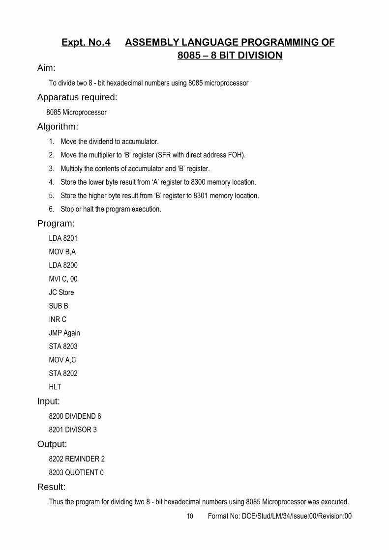
Expt. No.6 ASSEMBLY LANGUAGE PROGRAMMING OF
8085 –SORTING IN DESCENDING ORDER
Aim:
To sort an array of ‘n’ element in descending order using 8085 microprocessor
Apparatus Required:
8085 Microprocessor
Algorithm:
1. Load the R6 register with the value of "length of the array = 1".
2. Load the R7 register with the value of "length of the array = Iteration no".
3. Load the R0 register with the array starting address.
4. Load R1 register with the last data and accumulator with the second data from the last one.
5. Subtract the R1 register from the accumulator.
6. Check the carry flag.
7. If carry flag is not there, then A register is greater which means second data is larger than the first
data. So, do not exchange the A and R1 register.
8. If carry flag is there, then R1 register is greater which means first data is larger than the second data.
So, exchange the first address location data and second address location data.
9. Check the R7 register. If R7 is not equal to zero, repeat from the 4 th step for second and third data
processing. Else decrement R6.
10. Check the R6 register. If R6 is not equal to zero, repeat from the 4 th step for second iteration.
11. Stop the program.
Program:
LXI H, 8200
MOV E, M
MOV B, M
MOV C, E
INX H
DCR C
MOV A, M
INX H
CMP M
JNC Ahead
MOV D,M
MOV M,A
14 Format No: DCE/Stud/LM/34/Issue:00/Revision:00
DCX H
MOV M,D
INX H
DCR C
JNZ
DCR B
JNZ
HLT
Input:
8200 No. of Elements 6
8201 DATA 1 06
8202 DATA 2 18
8203 DATA 3 1B
8204 DATA 4 2C
8205 DATA 5 1A
8206 DATA 6 15
Output:
8201 DATA 1 2C
8202 DATA 2 1B
8203 DATA 3 1A
8204 DATA 4 18
8205 DATA 5 15
8206 DATA 6 06
Result:
Thus the program to sort an array of ‘n’ element in descending order using 8085 microprocessor was
executed.
15 Format No: DCE/Stud/LM/34/Issue:00/Revision:00
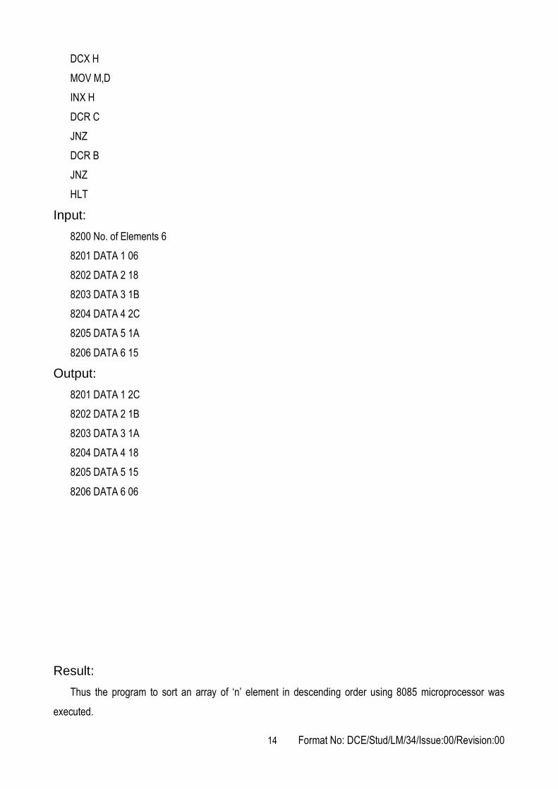
Expt. No.7 ASSEMBLY LANGUAGE PROGRAMMING OF
8085 – BCD TO HEX CONVERSION
Aim:
To write an assembly language program to convert 8 - bit two digit BCD number system into hexadecimal
number system
Apparatus Required:
8085 Microprocessor
Algorithm:
1. Start the program.
2. Get the data from the 8300 memory location to R5 register (R5 = 99).
3. Separate the MSB and LSB of R5 register using ANL 0FH and ANL F0H commands.
4. Move the MSB to accumulator and LSB to R2 register (A= 09, R2 = 09).
5. Multiply the MSB with 0AH data (09 x 0A = 5A).
6. Add the accumulator with LSB of the data (5A+9 = 63).
7. Move the accumulator to 8301 memory location (8301 = 63).
8. Stop the program.
Program:
ORG 0000H
MOV DPTR,#8300h
MOVX A, @DPTR
MOV R5,A
ANL A, #0F0h
SWAP A
MOV R1,A
MOV A,R5
ANL A, #0Fh
MOV R2,A
MOV A,R1
MOV B, #0Ah
MUL AB
ADD A,R2
INC DPTR
MOVX @DPTR, A
HLT: SJMP HLT
16 Format No: DCE/Stud/LM/34/Issue:00/Revision:00
Input:
8301 BCD Data =
Output:
8301 HEX Data =
Result:
Thus the assembly language program was written to verify the Boolean equation and executed.
Outcome:
From this experiment, students will be able to read and write the 8085 assembly language program and
understood about addition, subtraction, multiplication, division, sorting and code conversions of hexadecimal
codes which is used in automated systems.
Applications:
A microprocessor based systems are used in instructions, automatic testing product, speed control of
motors, traffic light control, Washing machines, microwave ovens, mobile phones etc.
1. What is a Microprocessor?
2. What are the basic functional blocks of a microprocessor?
3. What are the advantages of microprocessor based system?
4. What are the disadvantages of microprocessor based system?
5. What is a bus?
6. Define – Bit, Byte and Word
7. What is meant by an instruction set?
8. What is meant by band width?
9. Define – Mnemonics
10. Define – Op-code and operand
11. What is the difference between the microprocessor and micro controller?
12. How many interrupts are there in 8085?
13. What are the various registers used in 8085?
14. What is a flag?
15. What are the various flags used in 8085?
16. What is meant by program counter?
17. In 8085 which is called as higher order / low order register?
18. What are the drawbacks of first generation microprocessors?
19. What is the difference between CPU bus and System bus?
Viva - voce

17 Format No: DCE/Stud/LM/34/Issue:00/Revision:00
Expt. No.8 STEPPER MOTOR INTERFACE WITH 8051–
MICROCONTROLLER
Aim:
To run a stepper motor at different speeds and different directions using 8051 assembly language
Apparatus required:
1. Stepper motor
2. Interface board
Procedure:
1. Switch 'ON' the micro controller.
2. Initialize the starting address.
3. Enter the mnemonics code in the microcontroller.
4. Reset the microcontroller.
5. Execute the program.
Program:
ORG 4100H
START
MOV DPTR, #4500H
MOV R0, #04
MOVX A, @DPTR
PUSH DPH
PUSH DPL
MOV DPTR, #FFCOH
MOV R2, #04H
MOV R1, #FFH
MOV R3, #FFH
DJNZ R3, DLY
DJNZ R1, DLY1
DJNZ R2, DLY1
MOV @DPTR, A
POP DPL
POP DPH
INC DPTR
DJNC R0,J0
SJMP START
END

18 Format No: DCE/Stud/LM/34/Issue:00/Revision:00
Result:
Thus the program to run the stepper motor at different speeds and different directions was written using
8051 assembly language and executed.
Outcome:
From this experiment, students will be able to learn the working principle of stepper motor using 8051
microcontroller
Applications:
The stepper motor is used for precise positioning with a motor, such as hard disk drives, robotics,
antennas, telescopes, and some toys. Stepper motors cannot run at high speeds, but have a high holding
torque.
1. What is microcontroller?
2. What is meant by baud rate?
3. List the interrupts of 8051 – Microcontroller.
4. What are the four distinct types of memory in 8051?
5. What are the register banks in 8051 microcontroller?
6. What is the general purpose registers of 8051?
7. What is the asynchronous data transmission format of 8051 serial port?
8. What is meant by memory – Mapped I/O?
9. Difference between RET and RET 1 instruction in 8051.
10. What is the size of RAM and ROM in 8051?
11. List the various flags in the PSW register.
12. What are the different types of instructions?
13. What are the instructions to access the program memory?
14. What are addressing modes?
15. What is stepper motor?
16. What are the applications of stepper motor in mechatronics system?
17. What is meant by ALU? State its function.
18. What are the interface methods available in stepper motor?
19. State the application of stepper motor and servo motor in mechatronic systems.
20. What is meant by key bounce?
Viva - voce

19 Format No: DCE/Stud/LM/34/Issue:00/Revision:00
Expt. No.9 MICRO CONTROLLER BASED TRAFFIC LIGHT SYSTEM
Aim:
To control a traffic light system by using 8051 microcontroller
Apparatus required:
1. Traffic light control system
2. Interface board
Procedure:
1. Switch 'ON' the micro controller.
2. Initialize the starting address.
3. Enter the mnemonics code in the microcontroller.
4. Reset the microcontroller.
5. Execute the program.
Program:
ORG 4100H
MOV A,#80H
FF 0F MOV DPTR,#CONTRL
MOVX @DPTR,A
MOV R4,#04H
MOV DPTR,#LOOK1
MOV R2,DPH
MOV R3,DPL
MOV DPTR,#LOOK
MOV R0,DPH
MOV R1,DPL
GO:
MOVX A,@DPTR
MOV R0,DPH
MOV R1,DPL
MOV DPTR,#PORTA
MOVX @DPTR,A
INC R1
MOV DPH,R0
MOV DPL,R1
MOVX A,@DPTR

20 Format No: DCE/Stud/LM/34/Issue:00/Revision:00
MOV R0,DPH
MOV R1,DPL
MOV DPTR,#PORTB
MOVX @DPTR,A
INC R1
MOV DPH,R0
MOV DPL,R1
MOVX A,@DPTR
MOV R0,DPH
MOV R1,DPL
MOV DPTR,#PORTC
MOVX @DPTR,A
INC R1
LCALL DELAY
MOV DPH,R2
MOV DPL,R3
MOVX A,@DPTR
MOV R2,DPH
MOV R3,DPL
MOV DPTR,#PORTA
MOVX @DPTR,A
INC R3
MOV DPH,R2
MOV DPL,R3
MOVX A,@DPTR
MOV R2,DPH
MOV R3,DPL
MOV DPTR,#PORTB
MOVX @DPTR,A
INC R3
MOV DPH,R2
MOV DPL,R3
MOVX A,@DPTR
MOV R2,DPH
MOV R3,DPL

21 Format No: DCE/Stud/LM/34/Issue:00/Revision:00
MOV DPTR,#PORTC
MOVX @DPTR,A
INC R3
LCALL DELAY1
MOV DPH,R0
MOV DPL,R1
DJNZ R4,GO
LCALL START
DELAY: MOV R5,#12H
MOV R6,#0ffH
MOV R7,#0ffH
DJNZ R7,L1
DJNZ R6,L2
DJNZ R5,L3
RET
DELAY1: MOV R5,#12H
MOV R6,#0ffH
MOV R7,#0ffH
DJNZ R7,L4
DJNZ R6,L5
DJNZ R5,L6
RET
LOOK: DB 44H,27H,12H
92 2B 10 DB 92H,2BH,10H
84 9D 10 DB 84H,9DH,10H
84 2E 48 DB 84H,2EH,48H
LOOK1: DB 48H, 27H, 12H
419E 92 4B 10 DB 92H, 4BH, 10H
41A1 84 9D 20 DB 84H, 9DH, 20H
41A4 04 2E 49 DB
Result:
Thus the program to control traffic light control system was written using 8051 assembly language and
executed.

22 Format No: DCE/Stud/LM/34/Issue:00/Revision:00
Outcome:
From this experiment, students will be able to read and write the 8051 assembly language program and
learn the working principle of traffic light control system using 8051 microcontroller used in embedded system.
Applications:
A microcontroller can be considered a self-contained system with a processor, memory and peripherals
and can be used as an embedded system. The majority of microcontrollers in use today are embedded in
other machinery, such as automobiles, telephones, appliances, and peripherals for computer systems.
1. What is meant microcontroller?
2. Distinguish between parallel data transfer and serial data transfer.
3. What are the interfacing devices used in 8051?
4. What is meant by synthesis?
5. Define – Compiler
6. Define – Interpreter
7. Define – Assembler
8. Define – Interrupt Priority
9. Define – Sampling Rate
10. Define – Fetch Cycle
11. How will you interface the I/O devices?
12. What is meant by peripheral mapped I/O?
13. What is the address range of the bit-addressable internal memory of the 8051?
14. Why microcontrollers are often called single chip computers?
15. List the bit size for automobile engine control and robot arm.
16. Define – Stock Pointer
17. Define – PSW
18. Distinguish between register and flags.
19. What is meant by sub-routines and nested sub-routines?
20. Distinguish between direct addressing mode and indexed addressing mode.
Viva - voce

23 Format No: DCE/Stud/LM/34/Issue:00/Revision:00
Expt. No.10 SPEED MEASUREMENT OF DC MOTOR USING
OPTICAL SENSOR
Aim:
To measure the speed of DC motor using optical sensor
Apparatus required:
1. VTT-01 trainer
2. DC servomotor
3. Patch chords
Procedure:
1. Interface the DC motor with VTT-01 trainer (Back Panel).
2. Switch 'ON' the trainer and select the speed transducer using push button.
3. Connect the multi meter across O/P 5 and T13 in "DC - Volt" mode.
4. Vary the control voltage from 0 - 5V in stepwise manner.
5. Measure the output voltage and the speed displayed.
6. Plot the graph between speed and output voltage.
Tabulation:
Sl.No. Speed (rpm) Output Voltage (mV)
Result:
Thus the speed of DC motor is measured using optical sensor.
Outcome:
From this experiment, students will be able to learn the DC motor speed control methods and the working
principle of optical sensor used in automotive applications.
Applications:
DC motor is an industry workhorse for high and low power, fixed and variable speed electric drives.
Applications range from cheap toys to automotive applications. They are inexpensive to manufacture and
are used in variable speed household appliances such as sewing machines and power tools.

24 Format No: DCE/Stud/LM/34/Issue:00/Revision:00
1. What is a principle of optical encoder?
2. What is the principle of operation of a D.C Motor?
3. What are the various types of D.C. motors?
4. What is the control methods used in D.C. motors?
5. Compare the functions of series wound D.C. motors and shunt wound D.C. motors.
6. What is back e.m.f or counter e.m.f?
7. How can you reverse the direction of rotation of a D.C Motor?
8. What happens when a D.C motor is connected across an A.C supply?
9. What are the types of starters used for starting of D.C Motors?
10. What are the factors to be considered in the selection of a motor?
11. What is the role of a commutator?
12. What are the different types of losses in DC Machines?
13. What is meant by embedded systems?
14. What are the two types of position encoders?
15. What is meant by an encoder?
16. What are the various types of encoder?
17. What is meant by an incremental encoder?
18. What is meant by an absolute encoder?
Viva - voce

25 Format No: DCE/Stud/LM/34/Issue:00/Revision:00
Expt. No.11 STUDY OF VARIOUS TYPES OF TRANSDUCERS
STRAIN MEASUREMENT SYSTEM
Aim:
To study the characteristics between the strains applied to the cantilever beam strain sensor and the
bridge voltage
Apparatus required:
1. VTT - 01 trainer
2. Multimeter (mV)
3. Cantilever beam strain sensor setup
4. Weight (100 gram x 10 Nos.)
5. Power chord
Formula to be used:
Theoretical Strain:
Where,
Applied load to the beam (P) = 1 kg
Thickness of the beam (t) = 0.25 cm
Breath of the beam (B) = 2.8 cm
Length of the beam (L) = 21.58 cm
Young's modulus (Y) of the beam = 2 × 10⁶ kg /cm2
Procedure:
1. Install the cantilever beam strain sensor setup and interface the 9 pin D connector with VTT-01
2. Connect the multimeter in millivolt mode across T2 and T3 for bridge voltage measurement.
3. Switch 'ON' the module and select the strain transducer by switching the select button.
4. Initially, unload the beam and nullify the bridge voltage using a fine adjustment POT.
5. On applying the load to the beam, strain will develop on the beam. Then measure the bridge voltage
(mV) across T2 and T3.
6. Gradually increase the load on the beam and note down applied load and the bridge voltage (mV).
7. Tabulate the values of applied load, theoretical strain and the bridge voltage (mV).
8. Plot a graph between theoretical strain versus bridge voltage (mV).

26 Format No: DCE/Stud/LM/34/Issue:00/Revision:00
Tabulation:
Applied load (gram) Theoretical
strain Actual strain
Bridge output voltage (mV)
% Error
Result:
Thus the characteristics between the strain applied to the cantilever beam strain sensor and the bridge
voltage was studied and the graph was plotted.

27 Format No: DCE/Stud/LM/34/Issue:00/Revision:00
Expt. No.12 EXPERIMENTATION ON THE CHARACTERISTICS OF
LVDT POSITION SENSOR WITH RESPECT TO THE
DIFFERENTIAL VOLTAGE
Aim:
To study the characteristics of LVDT position sensor with respect to the differential voltage
Apparatus required:
1. VTT-01 trainer
2. LVDT setups
3. Multimeter (CRO)
4. Power chord
Procedure:
1. Install the LVDT position sensor and interface the 9 pin D connector with VTT-01 trainer (Back panel).
2. Switch 'ON' the trainer and select the displacement transducer using "select" button.
3. Connect the multimeter (in AC - mV mode) CRO across the T6 and T7 for the differential voltage
measurement.
4. Adjust the micrometer to 0 mm displacement and tune the fine adjustment POT to 0 mm displacement
on display.
5. Adjust the micrometer to 20 mm displacement and tune the span adjustment POT to 20 mm on the
display. The voltage across the O/P 2 and T7 should be 5V.
6. Repeat the fine and span calibration until the core displacement is 0 for 0mm displacement in
micrometer and 20 for 20 mm displacement in micrometer.
7. After completion of the calibration, give the displacement from the micrometer to the core of the LVDT
sensor.
8. Gradually increase the micrometer displacement from 0 mm to 20 mm and note down the forward
core displacement on the display and differential voltage (mV).
9. Similarly, decrease the micrometer displacement from 20 mm to 0 mm and note down the reverse
core displacement on the display and differential voltage (mV) across O/P 2 and T7.
10. Tabulate the readings of the core displacement, micrometer displacement and differential voltage
(mV).
11. Plot the graph between core displacement (mm) and differential voltage (mV).
28 Format No: DCE/Stud/LM/34/Issue:00/Revision:00
Tabulation:
Result:
Thus the characteristics of the LVDT position sensor with respect to the differential voltage were studied.
Micrometer displacement (mm) Core displacement (mm) Differential voltage (mV)

29 Format No: DCE/Stud/LM/34/Issue:00/Revision:00
Expt. No.13 EXPERIMENTATION ON THE CHARACTERISTICS OF
THE PRESSURE CELL WITH RESPECT TO THE
BRIDGE VOLTAGE
Aim:
To study the characteristics of the pressure cell with respect to the bridge voltage
Apparatus required:
1. VTT - 01 trainer
2. Multimeter (mV)
3. Pressure cell setup
4. Power chord
Procedure:
1. Install the pressure cell setup and interface the 9 pin D connector with VTT-01 trainer (Back panel).
2. Connect the multimeter (DC-mV) across T9 and T10 for bridge voltage measurement.
3. Switch 'ON' the module.
4. Initially, open the air release valve and exhaust the tank inlet air and nullify the bridge voltage by using
fine adjustment POT.
5. Now, close the air release valve. By pressing the pump piston, the pump sucks the air from
atmosphere and supplies it to the cylinder. Then, the pressure will be developed in the cylinder and
now measure the bridge voltage (mV) across T9 and T10.
6. Gradually increase the pressure by pressing the pump piston and note down the bridge voltage (mV)
for corresponding gauge pressure.
7. Tabulate the readings and plot the graph between gauge pressure and bridge voltage (mV).
Tabulation:
Gauge Pressure (psi) Bridge voltage (mV)
Result:
Thus the characteristics of the pressure cell with respect to bridge voltage were studied.

30 Format No: DCE/Stud/LM/34/Issue:00/Revision:00
Expt. No.14 TEMPERATURE MEASUREMENT SYSTEM
Aim:
To study the characteristics of temperature measurement system and the accuracy of signal conditioning
board
Apparatus required:
1. VTT-01 trainer
2. Water bath
3. Thermometer
4. Multimeter
5. Power chord
Formula:
Procedure:
1. Patch the wires of RTD to the VTT-01 trainer (Back panel).
2. Switch 'ON' the VTT-01 trainer. Select the temperature transducer by "select" button.
3. Now adjust the fine potentiometer to read 30°C at the display. This is done for initial setup of the
trainer and this adjustment should not be disturbed.
4. Insert the RTD into the water bath and note the temperature without any heating at ambient condition.
5. Place the multimeter in "voltage mode" across the O/P 4 and T14 terminals.
6. Gradually start heating the water bath and note down the actual temperature, output voltage and the
displayed temperature of the trainer simultaneously.
7. Plot the graph for temperature Vs voltage.
8. Calculate the % error and plot the graph for temperature Vs % error
Tabulation:
Result:
Thus the study of temperature measurement system and the accuracy of signal conditioning board were
done and the graph is drawn.
Actual temperature (oC) Output voltage (V) Displayed temperature (oC) % Error

31 Format No: DCE/Stud/LM/34/Issue:00/Revision:00
Outcome:
From this experiment, students will be able to understand the working principle of strain measurement
system, pressure measurement system, temperature measurement system and displacement measurement
system used in automation and control systems.
Applications:
Usually a transducer converts a signal in one form of energy to a signal in another. Transducers are often
employed at the boundaries of automation, measurement, and control systems, where electrical signals are
converted to and from other physical quantities (energy, force, torque, light, motion, position, etc.).
1. What is meant by sensor?
2. What is meant by strain?
3. What is meant by Transducer?
4. Write an example for a transducer and state its transduction principle.
5. Distinguish between a measurement system and a control system.
6. What are the various types of control system?
7. Define – Hysteresis
8. Define – Sensitivity
9. Write two factors that need to be considered in selecting a sensor for a particular application.
10. What is meant by signal conditioning?
11. What is meant by RTD? State its applications.
12. What is meant by see back effect?
13. Distinguish between closed loop system and open loop system.
14. What are the various elements of a closed loop system for controlling the temperature?
15. What are the types of strain gauges?
16. Define - LVDT
17. What is a Hall Effect sensor?
18. Define – Range and Span
19. Define – Accuracy and Precision
20. Define – Non-linearity error
Viva - voce

32 Format No: DCE/Stud/LM/34/Issue:00/Revision:00
STUDY OF HYDRAULIC, PNEUMATIC AND ELECTRO-PNEUMATIC
CIRCUITS
Expt. No.15 ACTUATION OF SINGLE ACTING CYLINDER USING A TWO WAY PRESSURE VALVE
Aim:
To construct a pneumatic circuit to actuate the single acting cylinder using a two-way pressure valve
Apparatus required:
1. Compressor
2. FRL unit
3. Two-way pressure valve
4. Single acting cylinder
Procedure:
1. Draw the circuit diagram.
2. Connect the compressed air supply to FRL unit.
3. The output of FRL unit is directly connected to both the 3/2 push button valves.
4. The output of the 3/2 push button valve is connected to the AND gate input.
5. When both the push buttons are pressed, the cylinder gets activated.
Circuit diagram:
Result:
Thus the pneumatic circuit using a two way pressure valve was constructed and executed.

33 Format No: DCE/Stud/LM/34/Issue:00/Revision:00
Expt. No.16 ACTUATION OF DOUBLE ACTING CYLINDER USING ELECTRICAL PUSH BUTTON SWITCH IN METER - IN
CIRCUIT Aim:
To study the actuation of double acting cylinder using electrical push button switch in meter - in circuit
Apparatus required:
1. Pump unit
2. 4/3 hand lever valve
3. Double acting cylinder
4. One way flow control valve
5. Push button
6. Valve solenoid
7. Electrical connection 24 V
Procedure:
1. Draw the circuit.
2. Switch 'ON' the single phase motor.
3. When the push button in the LHS is pressed, the solenoid valve S1 gets actuated.
4. Then the oil will flow through the one way flow control valve, the piston moves on the forward
direction.
5. When the push button on the RHS is pressed the solenoid valve (S2) will get activated.
6. Then the oil will flow through the one way flow control valve to push the piston in reverse direction.

34 Format No: DCE/Stud/LM/34/Issue:00/Revision:00
Circuit diagram:
Result:
Thus the actuation of double acting cylinder using electrical push button switch in meter - in circuit was
experimentally studied.

35 Format No: DCE/Stud/LM/34/Issue:00/Revision:00
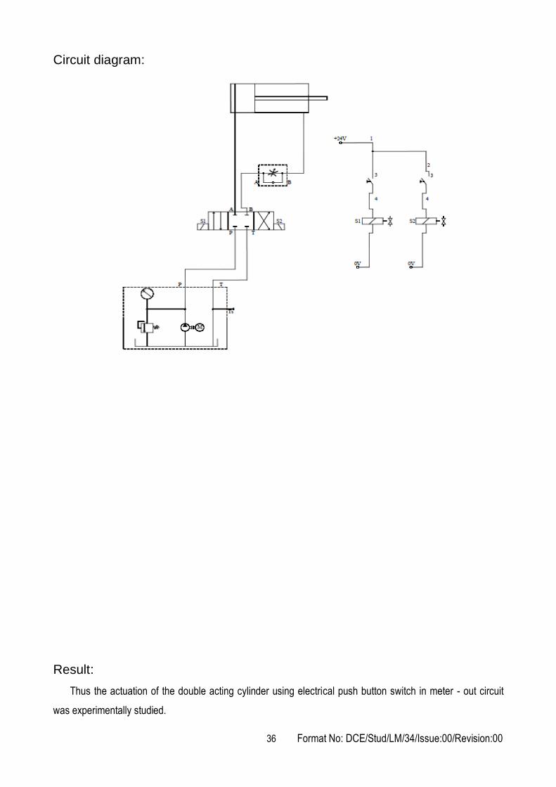
Expt. No.17 ACTUATION OF DOUBLE ACTING CYLINDER USING ELECTRICAL PUSH BUTTON SWITCH IN METER - OUT
CIRCUIT Aim:
To study the actuation of double acting cylinder using electrical push button switch in meter - out circuit
Apparatus required:
1. Pump unit
2. 4/3 hand lever valve
3. Double acting cylinder
4. One way flow control valve
5. Push button
6. Valve solenoid
7. Electrical connection 24V
Procedure:
1. Draw the circuit.
2. Switch 'ON' the single phase motor.
3. When the push button in the LHS is pressed, the solenoid valve S1 gets actuated.
4. Then the oil will flow through the one way flow control valve, the piston moves on the reverse
direction.
5. When the push button on the RHS is pressed the solenoid valve (S2) will get activated.
6. Then the oil will flow through the one way flow control valve to push the piston in forward direction.
36 Format No: DCE/Stud/LM/34/Issue:00/Revision:00
Circuit diagram:
Result:
Thus the actuation of the double acting cylinder using electrical push button switch in meter - out circuit
was experimentally studied.
37 Format No: DCE/Stud/LM/34/Issue:00/Revision:00
Expt. No.18 ACTUATION OF ROTARY ACTUATOR USING ELECTRICAL PUSH BUTTON SWITCH IN METER-OUT
CIRCUIT Aim:
To study the actuation of the rotary actuator using electrical push button switch in meter - out circuit
Apparatus required:
1. Pump unit
2. 4/3 hand lever valve
3. Push button
4. Valve solenoid
5. Semi-rotary actuator
6. One way flow control valve
7. Electrical connection 24V
Procedure:
1. Draw the circuit.
2. Switch on the single phase motor.
3. When the push button in the LHS is pressed, the solenoid valve S1 gets actuated.
4. Then the oil will flow through the one way flow control valve, the rotary actuator rotates on the forward
direction.
5. When the push button on the RHS is pressed the solenoid valve (S2) will get activated.
6. Then the oil will flow through the one way flow control valve to rotate the rotary actuator on the reverse
direction.

38 Format No: DCE/Stud/LM/34/Issue:00/Revision:00
Circuit diagram:
Result:
Thus the actuation of the rotary actuator using electrical push button switch in meter - out circuit was
experimentally studied.

39 Format No: DCE/Stud/LM/34/Issue:00/Revision:00
Expt. No.19 ACTUATION OF ROTARY ACTUATOR USING ELECTRICAL PUSH BUTTON SWITCH IN MANUAL
MODE Aim:
To study the actuation of the rotary actuator using electrical push button switch in manual mode
Apparatus required:
1. Pump unit
2. 4/3 hand lever valve
3. Semi-rotary actuator
4. One way flow control valve
5. Push button
6. Valve solenoid
Procedure:
1. Draw the circuit.
2. Switch on the single phase motor.
3. When the push button in the LHS is pressed, the solenoid valve S1 gets actuated.
4. Then the oil will flow through the one way flow control valve, the rotary actuator rotates on the reverse
direction.
5. When the push button on the RHS is pressed the solenoid valve (S2) will get activated.
6. Then the oil will flow through the one way flow control valve to rotate the rotary actuator on the forward
direction.

40 Format No: DCE/Stud/LM/34/Issue:00/Revision:00
Circuit diagram:
Result:
Thus the actuation of the rotary actuator using electrical push button switch in manual mode was
experimentally studied.

41 Format No: DCE/Stud/LM/34/Issue:00/Revision:00
Expt. No.20 CONTINUOUS RECIPROCATION OF SINGLE ACTING CYLINDER
Aim:
To construct a pneumatic circuit to actuate the single acting cylinder using a pilot operated valve
Apparatus required:
1. Compressor
2. FRL unit
3. 3/2 Roller lever valve
4. Single acting cylinder
Procedure:
1. Draw the circuit diagram.
2. Connect the compressor air supply to FRL unit.
3. Connect the circuit as per the circuit diagram.
4. Observe the continuous reciprocation of single acting cylinder.
Circuit diagram:
Result:
Thus the continuous reciprocation of single acting cylinder was achieved using a pilot operated valve.
42 Format No: DCE/Stud/LM/34/Issue:00/Revision:00
Expt. No.21 CONTINUOUS RECIPROCATION OF DOUBLE ACTING CYLINDER USING 5/2 DOUBLE PILOT VALVE
Aim:
To construct a pneumatic circuit to control the continuous actuation of a double acting cylinder using 5/2
double pilot valve
Apparatus required:
1. Compressor
2. Double acting cylinder
3. 3/2 roller lever valve
4. 5/2 double pilot valve
5. Flow control valve
Procedure:
1. Draw the circuit diagram.
2. Connect compressor air supply to FRL unit.
3. One of the output of FRL unit is connected to 5/2 direction control unit (port 1).
4. The port 4 of DCV is connected to blank end of the double acting cylinder.
5. Another output of FRL unit is connected to the input of 3/2 roller lever valve to give pilot pressure for
5/2 double pilot valve.
6. The output of the roller lever valves are connected to both sides of the 5/2 double pilot valve.
7. When the FRL unit is opened, the high pressure air enters the blank end of the cylinder through the
DCV and the piston moves forward.
8. At the end of the forward stroke, the piston rod gives pressure to the roller lever valve. The output of
roller lever valve is sent to the double acting cylinder to change the position.
9. Now the high pressure air from the FRL unit is sent to the rod end of the double acting cylinder
through the second position of the DCV and the piston retracts.
10. At the end of the return stroke, the roller valve is pressed. The output of the roller valve is sent to the
DCV to change the position. This will be repeated until the FRL unit is closed.

43 Format No: DCE/Stud/LM/34/Issue:00/Revision:00
Circuit diagram:
Result:
Thus the continuous reciprocation of double acting cylinder was achieved.

44 Format No: DCE/Stud/LM/34/Issue:00/Revision:00
Expt. No.22 ACTUATION OF DOUBLE ACTING CYLINDER USING 5/2 SINGLE PILOT VALVE
Aim:
To construct an electro - pneumatic circuit to control the double acting cylinder using 5/2 single pilot valve
Apparatus required:
1. Compressor
2. FRL unit
3. 5/2 Single pilot valve
4. Electrical trainer
5. Double acting cylinder
6. Batch card
Procedure:
1. Draw the circuit diagram and connect the air supply to FRL unit.
2. Connect the electrical circuit from 24V DC source to ON/OFF switch.
3. Solenoids are connected to the push button switch.
4. When the solenoid is given the signal by a push button switch, the DCV is activated to actuate the
double acting cylinder.
5. When the OFF button is pressed, the signal to the solenoid is cut and the solenoids are de-energized
and the DCV comes to the original position to retract the cylinder.

45 Format No: DCE/Stud/LM/34/Issue:00/Revision:00
Circuit diagram:
Result:
Thus the double acting cylinder was controlled electrically using a 5/2 single pilot valve.

46 Format No: DCE/Stud/LM/34/Issue:00/Revision:00
Expt. No.23 ACTUATION OF DOUBLE ACTING CYLINDER USING 5/2 DOUBLE PILOT VALVE
Aim:
To construct a pneumatic circuit to actuate the double acting cylinder using 5/2 double pilot valve
Apparatus required:
1. Compressor
2. 3/2 push button valve
3. 5/2 double pilot valve
4. FRL unit
Procedure:
1. Draw the circuit diagram.
2. Connect the compressor air supply to FRL unit.
3. The outputs of FRL unit are directly connected to 3/2 push button valves inlet. The outputs of 3/2 push
button valves are connected to 5/2 double pilot valve.
4. 5/2 double pilot valve outputs are connected to double acting cylinder.
5. Observe the actuation of double acting cylinder.
Circuit diagram:
Result:
Thus the direction control of a double acting cylinder using 5/2 double pilot valve was achieved.

47 Format No: DCE/Stud/LM/34/Issue:00/Revision:00
Expt. No.24 ACTUATION OF SINGLE ACTING CYLINDER USING 3/2 SINGLE SOLENOID VALVE
(ELECTRO - PNEUMATIC) Aim:
To construct an electro - pneumatic circuit to actuate the single acting cylinder using 3/2 single solenoid
valve
Apparatus required:
1. Compressor
2. FRL unit
3. 3/2 Single solenoid valve
4. Electrical trainer
5. Single acting cylinder
6. Batch card
Procedure:
1. Draw the circuit diagram.
2. The electrical trainer gives voltage to pneumatic panel.
3. Connect the air supply to FRL unit.
4. The output of FRL unit is connected to the 3/2 single solenoid valve which is activated by the electrical
trainer.
5. The output of the 3/2 single solenoid valve is connected to the single acting cylinder.
6. Observe the actuation of the single acting cylinder using 3/2 single solenoid valve.
Circuit diagram:
Result:
Thus the actuation of single acting cylinder was carried out using 3/2 single solenoid valve.

48 Format No: DCE/Stud/LM/34/Issue:00/Revision:00
Expt. No.25 ACTUATION OF SINGLE ACTING CYLINDER USING ‘ON’ DELAY TIMER
Aim:
To construct an electro pneumatic circuit for the actuation of single acting cylinder using ON delay timer
Apparatus Required:
1. Compressor
2. FRL unit
3. Time delay valve
4. Electrical controller
5. Single acting cylinder
6. 3/2 Single solenoid valve
7. Batch card
Procedure:
1. The power supply is provided to electrical controller by interfacing the +ve to +ve and -ve to -ve.
2. The power supply is provided to pneumatic trainer from electrical controller by interfacing 24 +ve to
+ve and -ve to -ve.
3. Using the SPDT switch energize the corresponding solenoid to get the desired movement of the
cylinder.
4. Actuate the time delay circuit.
5. From the time delay, give connection to single acting cylinder according to the time set.
6. Design and draw the pneumatic circuit.
7. Test the circuit.
8. Observe the working of the cylinder.

49 Format No: DCE/Stud/LM/34/Issue:00/Revision:00
Circuit diagram:
Result:
Thus the actuation of single acting cylinder was carried out using ON delay timer.

50 Format No: DCE/Stud/LM/34/Issue:00/Revision:00
Expt. No.26 ACTUATION OF SINGLE ACTING CYLINDER USING ‘OFF’ DELAY TIMER
Aim:
To construct an electro pneumatic circuit for the actuation of single acting cylinder using OFF delay timer
Apparatus required:
1. Compressor
2. FRL unit
3. 3/2 Single acting cylinder
4. Electrical controller
5. Single acting cylinder
6. OFF delay timer
7. Batch card
Procedure:
1. Provide power supply to pneumatic trainer from electrical controller by inter facing 24+ and 24-.
2. Provide 24V power supply to timer.
3. Any one of the output of FRL unit direct connect to 3/2 single solenoid valve.
4. Single solenoid valve output is connecting to single acting cylinder.
5. Give +24V and -24V in Timer.
6. Output of Timer connected to solenoid coil.
7. Check the all circuit.
8. Observe the working of cylinder.
9. Observe the working circuit.

51 Format No: DCE/Stud/LM/34/Issue:00/Revision:00
Circuit diagram:
Result:
Thus the movement of single acting cylinder was carried out using OFF delay timer.

52 Format No: DCE/Stud/LM/34/Issue:00/Revision:00
Expt. No.27 DESIGN AND TESTING OF LOGICAL CONTROL OF DOUBLE ACTING CYLINDER USING ‘OR’ GATE
Aim:
To construct the pneumatic circuit to actuate a double acting cylinder using two identical push button
operated valves and a shuttle valve
Apparatus required:
1. Double acting cylinder
2. 3/2 way valves
3. 5/2 way valve
4. Compressor
5. Shuttle valve (OR gate)
Procedure:
1. The circuit is constructed as per the diagram.
2. The compressor is connected to the FRL unit.
3. The two 3/2 way valves are connected to the shuttle valve which is pilot operated.
4. When both of the push buttons are pressed or any one of the push button is pressed, the piston
extends and retracts upon release.
Circuit diagram:
Result:
Thus the circuit is constructed and tested as per the given application.

53 Format No: DCE/Stud/LM/34/Issue:00/Revision:00
Outcome:
From this experiment, students will be able to learn the working principles of hydraulic system, basic
pneumatic system and electro-pneumatic system were studied.
Applications:
Hydraulic circuits – precise control of larger forces e.g. earth movers, material handling equipment, etc.
Pneumatic circuits - A pneumatic system controlled through manual or automatic solenoid valves is selected when it provides a lower cost, more flexible, or safer alternative to electric motors and actuators.
Pneumatics also has applications in dentistry, construction, mining, and other areas.
Electro pneumatic circuits – industrial automation
1. What is meant by fluid power?
2. What is a check valve?
3. What is a solenoid valve?
4. Define – FRL unit
5. Define – DCV
6. Differentiate between meter-in and meter-out controls.
7. What is the function of an unloading valve?
8. What is the function of a sequence valve?
9. What is the function of a shuttle valve?
10. What is the function of a spool valve?
11. What is the function of a process control valve?
12. What is the function of a 2-way pressure valve?
13. Why hydraulic power is especially used in heavy works?
14. Where are pneumatic systems preferred?
15. Name the basic components of a hydraulic system.
16. What is the function of a relief valve in a hydraulic system?
17. Draw the symbols for a pressure relief valve and a pressure reducing valve.
18. What is meant by NC and NO contacts?
19. What is the function of a compressor?
20. What is the function of an accumulator?
Viva - voce
54 Format No: DCE/Stud/LM/34/Issue:00/Revision:00
MODELING AND ANALYSIS OF BASIC HYDRAULIC, PNEUMATIC
AND ELECTRICAL CIRCUITS USING PNEUMOSIM SOFTWARE
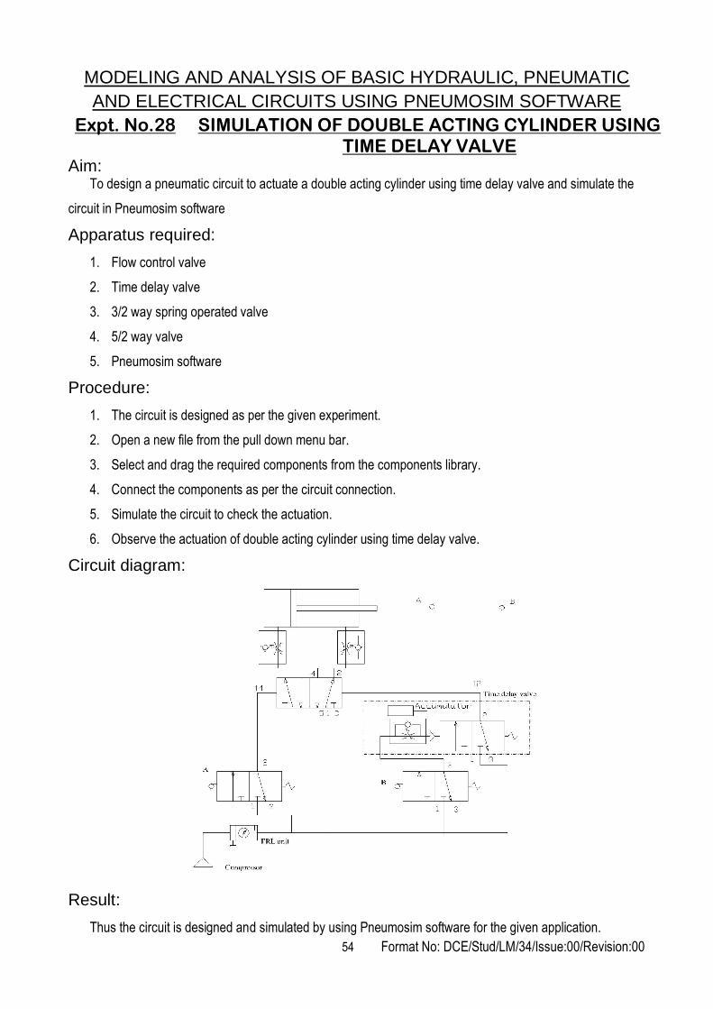
Expt. No.28 SIMULATION OF DOUBLE ACTING CYLINDER USING TIME DELAY VALVE
Aim: To design a pneumatic circuit to actuate a double acting cylinder using time delay valve and simulate the
circuit in Pneumosim software
Apparatus required:
1. Flow control valve
2. Time delay valve
3. 3/2 way spring operated valve
4. 5/2 way valve
5. Pneumosim software
Procedure:
1. The circuit is designed as per the given experiment.
2. Open a new file from the pull down menu bar.
3. Select and drag the required components from the components library.
4. Connect the components as per the circuit connection.
5. Simulate the circuit to check the actuation.
6. Observe the actuation of double acting cylinder using time delay valve.
Circuit diagram:
Result:
Thus the circuit is designed and simulated by using Pneumosim software for the given application.

55 Format No: DCE/Stud/LM/34/Issue:00/Revision:00
Expt. No.29 SIMULATION OF DOUBLE ACTING CYLINDERS IN
THE SEQUENCE OF A+ B+ B- A-
Aim:
To simulate double acting cylinders in the sequence of A+ B+ B- A- using Pneumosim software
Apparatus required:
1. Double acting cylinders
2. 5/2 double solenoid valve
3. Compressor
4. Limit Switches
5. Push button valves
6. Pneumosim Software
Procedure:
1. The circuit is designed as per the given experiment.
2. Open a new file from the pull down menu bar.
3. Select and drag the required components from the components library.
4. Connect the components as per the circuit connection.
5. Simulate the circuit to check the actuation.

56 Format No: DCE/Stud/LM/34/Issue:00/Revision:00
Circuit diagram:
Result:
Thus the simulation of double acting cylinders in the sequence of A+ B+ B- A- was achieved using
Pneumosim software.

57 Format No: DCE/Stud/LM/34/Issue:00/Revision:00
Expt. No.30 DESIGN AND TESTING OF PNEUMATIC CIRCUIT FOR
SINGLE CYCLE AUTOMATION OF MULTICYLINDERS
IN THE SEQUENCE OF A+ B+ A- B-
Aim:
To design and test a pneumatic circuit for single cycle automation of multicylinders in the sequence of
A+ B+ A- B-
Apparatus required:
1. Double Acting Cylinder
2. 5/2 way pilot operated valve
3. 3/2 way pilot operated valve
4. Roller operated valves
5. Pneumosim software
Procedure:
1. The circuit is designed as per the given application.
2. The compressor is connected to FRL un it .
3. The cylinder A extends when the roller operated valve R2 is actuated, which initiates the extension of
cylinder B.
4. This actuates the roller operated valve R4 which retracts the cylinder A.
5. The retracted cylinder A actuates the roller operated valve R1 which results in the retraction of
cylinder B.

58 Format No: DCE/Stud/LM/34/Issue:00/Revision:00
Circuit diagram:
Result:
Thus the pneumatic circuit for the given application is designed and tested.

59 Format No: DCE/Stud/LM/34/Issue:00/Revision:00
Expt. No.31 DESIGN AND TESTING OF PNEUMATIC CIRCUIT FOR
SINGLE CYCLE AUTOMATION OF MULTICYLINDERS
IN THE SEQUENCE OF A+ B+ B- A-
Aim:
To design and test a pneumatic circuit for single cycle automation of multicylinder in the sequence of
A+ B+ B- A- using cascading method
Apparatus required:
1. Double Acting Cylinder
2. 5/2 way pilot operated valve
3. 3/2 way pilot operated valve
4. Roller operated valves
5. Pneumosim software
Procedure:
1. The circuit is designed as per the given application.
2. The compressor is connected to FRL unit.
3. The cylinder A extends when the roller operated valve R2 is actuated which initiates the extension of
cylinder B.
4. This actuates the roller operated valve R4 which retracts the cylinder A.
5. The retracted cylinder A actuates the roller operated valve R1 which results in retraction of cylinder B.
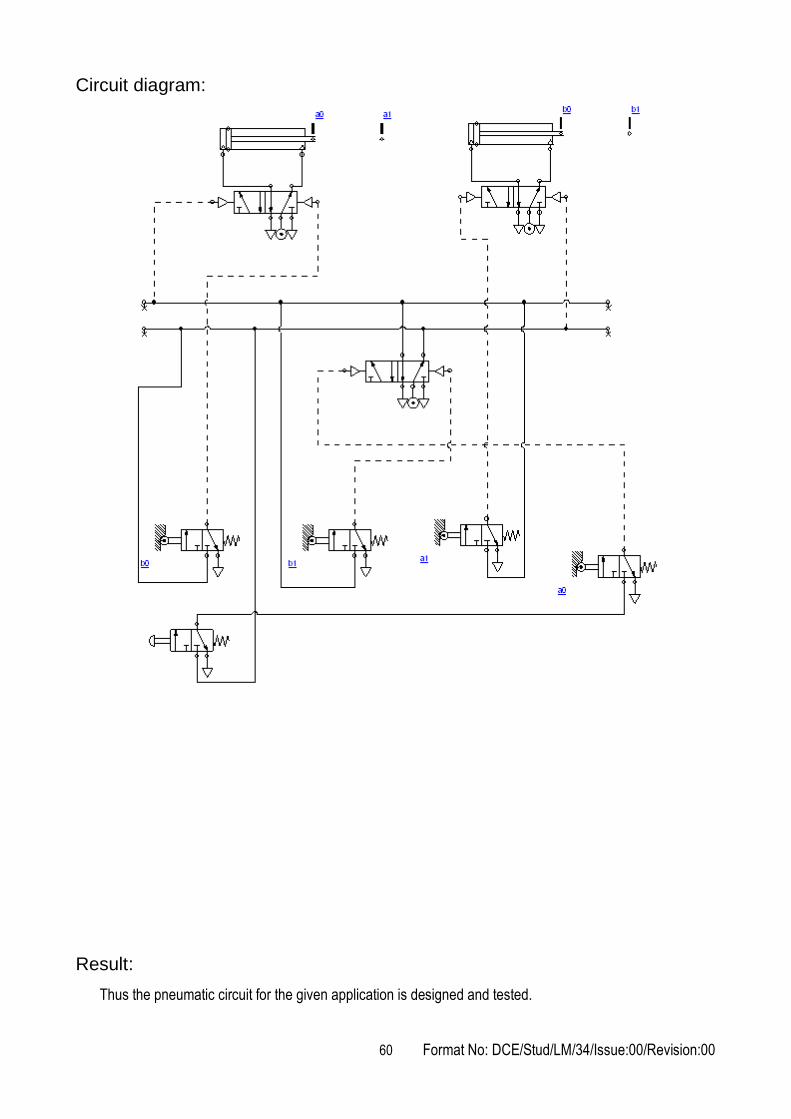
60 Format No: DCE/Stud/LM/34/Issue:00/Revision:00
Circuit diagram:
Result:
Thus the pneumatic circuit for the given application is designed and tested.

61 Format No: DCE/Stud/LM/34/Issue:00/Revision:00
Expt. No.32 DESIGN AND TESTING OF THE ACTUATION OF
DOUBLE ACTING CYLINDER USING ELECTRO
PNEUMATIC CIRCUIT
Aim:
To actuate a double acting cylinder using electrically operated solenoid valve
Apparatus required:
1. Double acting cylinder
2. 5/2 double solenoid valve
3. Compressor
4. Pneumosim software
Procedure:
1. The circuit is designed as per the given application.
2. The 5/2 double solenoid valve is operated by the switches S1 and S2.
3. When the start button is pressed, solenoid valve 1 gets energized and the cylinder moves in forward
direction.
4. At the end of the forward stroke, the switch s1 gets closed and it closes relay coil RL2, then the
solenoid valve 2 gets energized and the cylinder moves in reverse direction.
5. This process is repeated.
Circuit diagram:
Result:
Thus the electro pneumatic circuit for given application is designed and simulated.

62 Format No: DCE/Stud/LM/34/Issue:00/Revision:00
Expt. No.33 DESIGN AND TESTING OF MULTI CYCLE OPERATION OF DOUBLE ACTING CYLINDER USING ELECTRO
PNEUMATIC CIRCUIT
Aim: To actuate a double acting cylinder in multi cyclic continuous reciprocation using electrically operated
solenoid valve
Apparatus required:
1. Double acting cylinder
2. 5/2 double solenoid valve
3. Compressor
4. Pneumosim software
Procedure:
1. The circuit is designed as per the given application.
2. The 5/2 double solenoid valve is operated by switches S1 and S2.
3. When the start button is pressed, it closes the relay coil RL1 and solenoid valve 1 gets energized
which moves the cylinder forward direction.
4. At the end of the forward stroke, the switch S1 gets closed and it closes the relay coil RL2, then the
solenoid valve S2 gets energized and the cylinder moves in reverse direction.
5. At the end of the return stroke, the switch S2 gets closed and it closes relay coil RL2. Then the
solenoid valve 1 gets energized and the cylinder moves in forward direction.
6. This process is repeated.
Circuit diagram:
Result:
Thus the electro pneumatic circuit for given application is designed and simulated.
63 Format No: DCE/Stud/LM/34/Issue:00/Revision:00
Expt. No.34 DESIGN AND TESTING OF ELECTRO PNEUMATIC
CIRCUIT FOR SINGLE CYCLE AUTOMATION OF
MULTICYLINDERS IN THE SEQUENCE OF A+ B+ B- A-
Aim:
To design and test a electro pneumatic circuit for s ingle cyc le au tomation of mul t i
cy l inders in the sequence of A + B+ B - A -
Apparatus required:
1. Double acting cylinders
2. 5/2 double solenoid valve
3. Compressor
4. Pneumosim software
Procedure:
1. The circuit is designed as per the given application.
2. The compressor is connected to FRL un it .
3. The cylinder A extends when the solenoid valve S1 is actuated which further initiates the extension of
cylinder B.
4. This actuates the magnetic switch S1and the solenoid valve S4 which results in the retraction of
cylinder B.
5. The retracted cylinder B actuates the solenoid valve which results in retraction of cylinder A.

64 Format No: DCE/Stud/LM/34/Issue:00/Revision:00
Circuit diagram:
Result:
Thus the pneumatic circuit for the given application is designed and tested.
Outcome:
From this experiment, students will be able to understand the design and simulation of hydraulic and
pneumatic circuits using Hydro-sim and Pneumo-sim software respectively.
Applications:
Hydraulic circuits – precise control of larger forces e.g. earth movers, material handling equipment, etc.
Pneumatic circuits - A pneumatic system controlled through manual or automatic solenoid valves is selected when it provides a lower cost, more flexible, or safer alternative to electric motors and actuators.
Pneumatics also has applications in dentistry, construction, mining, and other areas.
Electro pneumatic circuits – industrial automation

65 Format No: DCE/Stud/LM/34/Issue:00/Revision:00
1. What is meant by an actuator?
2. What are the types of actuators?
3. What is a control valve?
4. What are the types of control valves?
5. What is a circuit control valve?
6. What is the function of flow control valve?
7. Distinguish between flow control and needle valve.
8. What is the function of time delay valve?
9. What is the function of pilot operated valve?
10. What is a quick exhaust valve?
11. What is the difference between a strainer and a filter?
12. Distinguish between hydraulics and pneumatics?
13. What is the purpose of a pressure regulator?
14. Why lubricator is used in pneumatic systems?
15. What are the advantages of hydro- pneumatics?
16. What is meant by logic control?
17. Name the different pneumatic position sensors.
18. How do you rate a compressor?
19. What is the use of a bleed –off circuit?
20. List the importance of Hydrosim and Pneumosim software.
Viva - voce

66 Format No: DCE/Stud/LM/34/Issue:00/Revision:00
STUDY OF PLC AND ITS APPLICATIONS
Expt. No.35 ACTUATION OF SINGLE ACTING CYLINDER WITH PLC
USING ‘AND’ GATE
Aim:
To actuate the single acting cylinder using AND gate with PLC ladder diagram
Apparatus required:
1. Compressor
2. FRL unit
3. Single acting cylinder
4. PLC
5. Versa Pro software
6. 3/2 single solenoid valve
Procedure:
1. Draw the circuit diagram.
2. Provide +24 V and -24 V from PLC trainer to electro pneumatic panel.
3. The output of the PLC (Q1) is connected to the input of 3/2 single solenoid valve.
4. Then open the Versa Pro software in desktop.
5. Interface the PLC with the system using RS232 cable.
6. Connect the air supply to FRL unit.
7. The output of FRL unit is connected to the 3/2 single solenoid valve.
8. Check the Ladder diagram.
9. Run the PLC. When two inputs (1i, 2i) are high, then output also will be high.

67 Format No: DCE/Stud/LM/34/Issue:00/Revision:00
Circuit diagram:
Result:
Thus the actuation of single acting cylinder with PLC using AND Gate was done.

68 Format No: DCE/Stud/LM/34/Issue:00/Revision:00
Expt. No.36 ACTUATION OF SINGLE ACTING CYLINDER WITH PLC
USING ‘OR’ GATE
Aim:
To actuate the single acting cylinder using OR Gate with PLC ladder diagram
Apparatus required:
1. Compressor
2. FRL unit
3. Versa Pro software
4. 3/2 single solenoid valve
5. PLC
6. Single acting cylinder
Procedure:
1. Draw the circuit diagram.
2. Provide +24 V and –24 V from PLC trainer to Electro pneumatic panel kit.
3. Open the Versa Pro software in desktop.
4. Interface the PLC with the system using RS232 cable.
5. Draw ladder diagram.
6. The output of PLC (q1) is connected to the input of solenoid valve.
7. Check the ladder diagram.
8. Connect the air supply to FRL unit.
9. Run the PLC. When any one input is high, then the output will be high.

69 Format No: DCE/Stud/LM/34/Issue:00/Revision:00
Circuit diagram:
Result:
Thus the actuation of single acting cylinder with OR Gate was done using PLC.

70 Format No: DCE/Stud/LM/34/Issue:00/Revision:00
Expt. No.37 ACTUATION OF SINGLE ACTING CYLINDER WITH PLC
USING 'ON' DELAY TIMER
Aim:
To actuate the single acting cylinder with PLC using ON delay timer
Apparatus required:
1. Compressor
2. FRL unit
3. 3/2 single solenoid valve
4. PLC
5. single acting cylinder
6. Versa Pro software
Procedure:
1. Draw the circuit diagram.
2. Provide +24 V and –24 V from PLC trainer to pneumatic panel kit.
3. Open the Versa Pro software in desktop.
4. Interface the PLC with PC using RS232 cable.
5. Draw a ladder diagram.
6. The output of PLC (q1) is connected to the input of solenoid valve.
7. Check the ladder diagram.
8. Connect the air supply to FRL unit.
9. Run the PLC upon the delay, the cylinder should be activated.
Circuit diagram:
Result:
Thus the actuation of single acting cylinder with PLC using ON delay timer was done.

71 Format No: DCE/Stud/LM/34/Issue:00/Revision:00
Expt. No.38 SIMULATE THE ACTUATION OF SINGLE ACTING
CYLINDER WITH PLC USING 'OFF' DELAY TIMER
Aim:
To actuate the single acting cylinder with PLC using OFF delay timer
Apparatus required:
1. Compressor
2. FRL unit
3. 3/2 single solenoid valve
4. PLC
5. single acting cylinder
6. Versa Pro software
Procedure:
1. Draw the circuit diagram.
2. Provide +24 V and –24 V from PLC trainer to pneumatic panel kit.
3. Open the Versa Pro software in desktop.
4. Interface the PLC with PC using RS232 cable.
5. Draw the ladder diagram.
6. The output of PLC (q1) is direct connected to the input of solenoid valve.
7. Check the ladder diagram.
8. Connect the air supply to FRL unit.
9. Run the PLC. Observe the working of single acting cylinder.

72 Format No: DCE/Stud/LM/34/Issue:00/Revision:00
Circuit diagram:
Result:
Thus the single acting cylinder is actuated with PLC using OFF delay timer.

73 Format No: DCE/Stud/LM/34/Issue:00/Revision:00
Expt. No.39 ACTUATION OF DOUBLE ACTING CYLINDER WITH PLC
USING 5/2 SINGLE SOLENOID VALVE
Aim:
To actuate the double acting cylinder with PLC using 5/2 single solenoid valve
Apparatus required:
1. Compressor
2. FRL unit
3. 5/2 single solenoid valve
4. PLC
5. Double acting cylinder
6. Versa Pro software
Procedure:
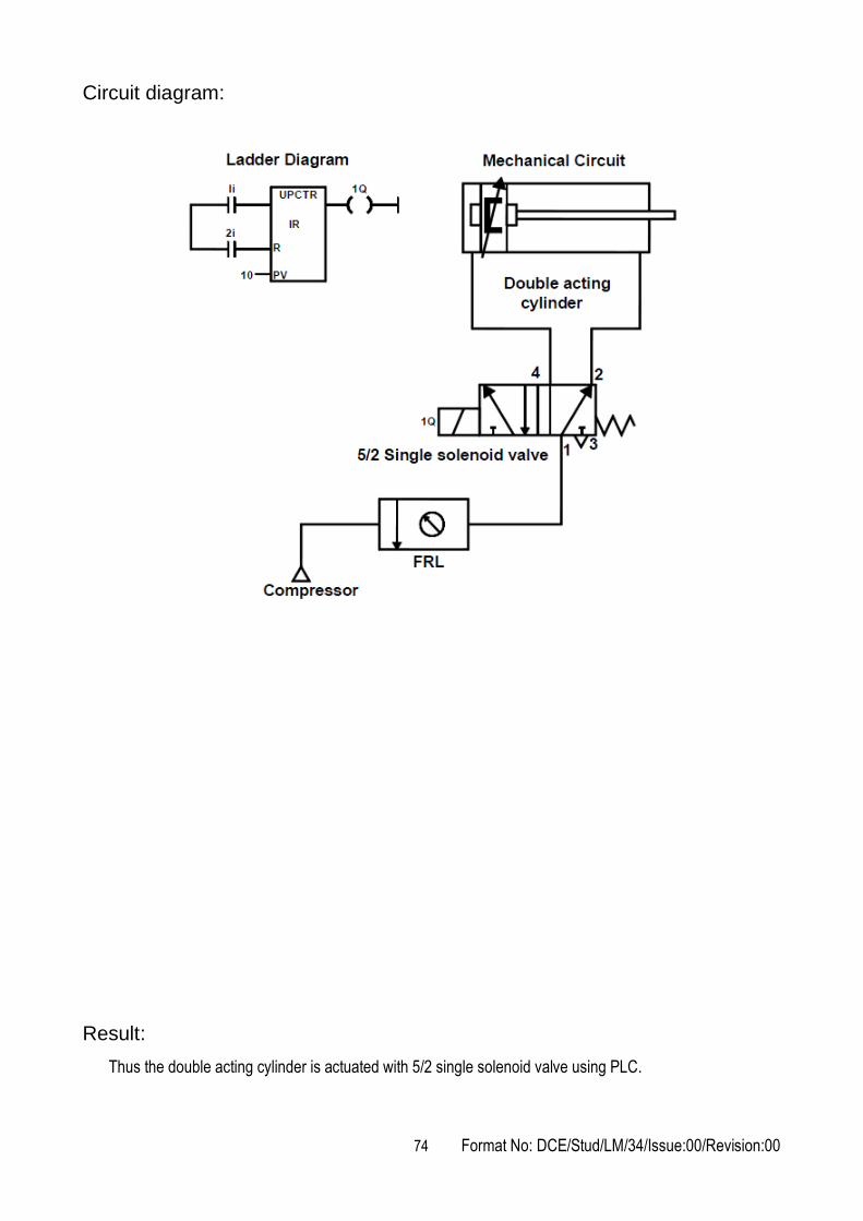
1. Draw the circuit diagram.
2. Provide +24 V and –24 V from PLC trainer to pneumatic panel kit.
3. Open the Versa Pro software in desktop.
4. Interface the PLC with PC using RS232 cable.
5. Draw the ladder diagram.
6. The output of PLC (q1) is connected to the input of solenoid valve.
7. Check the ladder diagram.
8. Connect the air supply to FRL unit.
9. Run the PLC input (1i), switch continuously ON and OFF. When it reaches the preset value (pv), the
cylinder gets actuated.
74 Format No: DCE/Stud/LM/34/Issue:00/Revision:00
Circuit diagram:
Result:
Thus the double acting cylinder is actuated with 5/2 single solenoid valve using PLC.

75 Format No: DCE/Stud/LM/34/Issue:00/Revision:00
Expt. No.40 AUTOMATIC ACTUATION OF SINGLE ACTING
CYLINDER USING PLC
Aim:
To simulate the automatic sequence of single acting cylinder by using PLC
Apparatus required:
1. Compressor
2. FRL unit
3. 3/2 single solenoid valve
4. PLC
5. Single acting cylinder
6. Versa Pro software
Procedure:
1. Draw the circuit diagram.
2. Provide +24 V and –24 V from PLC trainer to pneumatic panel kit.
3. Open the Versa Pro software in desktop.
4. Interface the PLC with PC using RS232 cable.
5. Draw the ladder diagram.
6. The output of PLC (q1) is connected to the input of solenoid valve.
7. Check the ladder diagram.
8. Connect the air supply to FRL unit.
9. Run the PLC. Observe the automatic reciprocation of single acting cylinder.

76 Format No: DCE/Stud/LM/34/Issue:00/Revision:00
Circuit diagram:
Result:
Thus the ladder diagram for the automatic running of single acting cylinder is drawn and executed.

77 Format No: DCE/Stud/LM/34/Issue:00/Revision:00
Expt. No.41 AUTOMATIC ACTUATION OF DOUBLE ACTING
CYLINDER USING PLC
Aim:
To simulate the automatic sequence of double acting cylinder using PLC
Apparatus required:
1. Compressor
2. FRL unit
3. 5/2 double solenoid valve
4. PLC
5. Double acting cylinder
6. Versa Pro software
7. Flow control valve
Procedure:
1. Draw the circuit diagram.
2. Provide +24 V and –24 V from PLC trainer to pneumatic panel kit.
3. Open the Versa Pro software in desktop.
4. Interface the PLC with PC using RS232 cable.
5. Draw the ladder diagram.
6. Both the outputs of PLC (q1 and q2) are directly connected to the inputs of solenoid valves.
7. Check the ladder diagram.
8. Connect the air supply to FRL unit.
9. Run the PLC. Observe the automatic reciprocation of double acting cylinder.

78 Format No: DCE/Stud/LM/34/Issue:00/Revision:00
Circuit diagram:
Result:
Thus the ladder diagram for the automatic running of double acting cylinder is drawn and executed.
Outcome:
From this experiment, students will be able to construct the ladder logic programming for various
applications using PLC.
Applications:
Programmable Logic Controller (PLC) is a special computer device used in industrial control systems.
Due to its robust construction, exceptional functional features like sequential control, counters and timers,
ease of programming, reliable controlling capabilities and ease of hardware usage – this PLC is used as more
than a special-purpose digital computer in industries as well as in other control-system areas.
The programmable logic controller is used not only for industrial purpose but also in civil applications
such as washing machine, elevators working and traffic signals control.

79 Format No: DCE/Stud/LM/34/Issue:00/Revision:00
1. What is a programmable logic controller?
2. What are the basic elements of a PLC?
3. What are the various approaches for entering the program for PLC?
4. What is a ladder diagram?
5. What is the purpose of an electrical timer?
6. Draw the general ladder rungs to represent a latch circuit.
7. How does a PLC differ from relay logic?
8. What is the use of JUMP control in PLC?
9. What are the features of a PLC?
10. What is meant by an internal relay in PLC?
11. Define – Logical Rack
12. What is the function of a PLC input module?
13. What is the function of a PLC output module?
14. List the basic sections of an I/O module.
15. What is the function of manually operated switch?
16. What is the function of mechanically operated switch?
17. What is the function of proximity switch?
18. Distinguish between a sequential and a combination control process.
19. Distinguish between the timed and instantaneous contacts of a pneumatic timer.
20. What determines the maximum speed of transitions that a PLC can count?
Viva - voce

80 Format No: DCE/Stud/LM/34/Issue:00/Revision:00
Expt. No.42 STUDY OF IMAGE PROCESSING TECHNIQUE
Introduction:
We use photography as a way of recording and presenting information visually in everyday life to create a
permanent record of our visual experiences. There are two major areas of application of digital image
processing techniques: 1) improvement of pictorial information for human interpretation and 2) processing of
scene data for autonomous machine perception. In machine perception, interest focuses on procedures for
extracting image information in a form suitable for computer processing.
Segmented images are formed from the generalized image by gathering its elements into sets that are
likely to be associated with meaningful objects in the scene.
In producing the segmented image, knowledge about the particular domain is important to save
computation and also to overcome problems of noise and inadequate data.
Geometric representations are used to capture the all-important data of two-dimensional and three-
dimensional shape. These geometric representations must be powerful enough to support complex and
general processing, such as 'simulation' of the effects of lighting and motion.
Relational models are complex assemblages of representations that are used to support sophisticated
high-level processing.
Image Formation:
Image formation occurs when a sensor registers radiation that has interacted with physical objects. Both
human vision and photography require a light source to illuminate a scene. The light interacts with the objects
in the scene and some of it reaches the observer, whereupon it is detected by the eyes or by a camera.
Information about the objects in the scene is recorded as variations in the intensity and colour of the detected
light.
There are other forms of energy, besides light, that can be used to create images. Light is merely the
visible portion of the electromagnetic (EM) spectrum. EM radiation is produced by the oscillation of electrically
charged material, and has wave-like properties. EM radiation can interact with matter in different ways,
depending on its wavelength. Images acquired at different wavelengths may have very different properties.
Electromagnetic (EM) Spectrum:
81 Format No: DCE/Stud/LM/34/Issue:00/Revision:00
Electromagnetic Radiation:
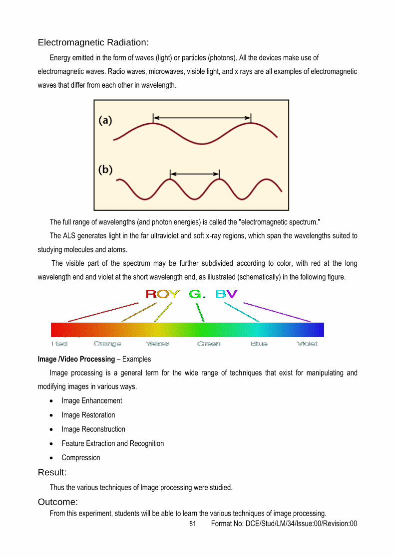
Energy emitted in the form of waves (light) or particles (photons). All the devices make use of
electromagnetic waves. Radio waves, microwaves, visible light, and x rays are all examples of electromagnetic
waves that differ from each other in wavelength.
The full range of wavelengths (and photon energies) is called the "electromagnetic spectrum."
The ALS generates light in the far ultraviolet and soft x-ray regions, which span the wavelengths suited to
studying molecules and atoms.
The visible part of the spectrum may be further subdivided according to color, with red at the long
wavelength end and violet at the short wavelength end, as illustrated (schematically) in the following figure.
Image /Video Processing – Examples
Image processing is a general term for the wide range of techniques that exist for manipulating and
modifying images in various ways.
Image Enhancement
Image Restoration
Image Reconstruction
Feature Extraction and Recognition
Compression
Result:
Thus the various techniques of Image processing were studied.
Outcome:
From this experiment, students will be able to learn the various techniques of image processing.

82 Format No: DCE/Stud/LM/34/Issue:00/Revision:00
Applications:
Digital image processing is the use of computer algorithms to perform image processing on digital images.
As a subcategory or field of digital signal processing, digital image processing has many advantages
over analog image processing e.g. remote sensing, digital camera, etc.
1. What is meant by lighting system?
2. Define – CCD
3. Define – Resolution
4. Define – Pixel
5. List the hardware oriented color model.
6. What is meant by gray level?
7. What is meant by sample seeding?
8. What is meant by image masking?
9. What is meant by image processing?
10. What is meant by image segmentation?
11. What is meant by image formation?
12. What is meant by image extraction?
13. What is meant by image restoration?
14. What is meant by feature extraction?
15. Define – Sampling and Quantization
16. What is meant by reflectance?
17. What is meant by image enhancement?
18. What are the different methods of image enhancement?
19. What are the various types of redundancies available in the image?
20. What are the various image compression techniques for reducing the size of images?
Viva - voce

83 Format No: DCE/Stud/LM/34/Issue:00/Revision:00
ADDITIONAL EXPERIMENT – BEYOND THE SYLLABUS
Expt. No.43 STUDY OF PID CONTROLLER
Aim:
To study and verify different control actions such as On-Off control, Proportional control, Derivative
control, Integral control, Proportional + Derivative control, Proportional + Integral, Proportional + Integral +
Derivative control with a temperature controller
Introduction to PID controller:
A controller is a device which compares the output of a system with the required conditions and converts
the error signal into control action, designated to reduce the error in a closed loop control the system. The
error might arrive due to changes in the conditions being controlled or due to change in set value.
Types of control actions:
1. On –off/two step mode control
In a two step mode, the controller is just a switch which is activated by the error signal and supplies
just an on-off correcting signal. It is a discontinuous control action. A consequence of this is that oscillations of
the controlled variable occur about the required condition. Two step control action is used where changes are
taking place very slowly i.e. with a process with a large capacitance. On-off controllers are not restricted to
mechanical switches such as bimetallic strips. Thyristor circuits can also be employed for rapid switching. This
control mode is not precise as it involves oscillations with long periodic times.
2. Proportional control
With the proportional mode, the size of the controller output is proportional to the size of the error
signal. It means that correction element receives a signal which is equal to the size of the correction required.
Fig. shows how the output of such a controller varies with the size and sign of the error. The linear
relationship between controller output and error tends to exist for a specific portion of the graph, which is
known as proportional band. Within the proportional band the equation of the straight line is represented as
Change in controller output from set point = Kp e
Where e is the error and Kp is a constant known as proportional constant. Kp is thus the gradient of
the straight line. The controller output is generally expressed in terms of percentage of the full range of
possible outputs within the proportional band. Generally a 50% controller output is specified for zero error. It is
not possible to achieve the change in the percent output of controller with the change in set value with zero
error setting. It requires a permanent error setting called 'offset'. The size of the offset is proportional to the
size of load changes and inversely proportional to Kp, so a higher value of Kp gives more steeper graph. This
mode is utilized in processes where the value of transfer function can be increased large enough so as to
reduce the offset to an acceptable level.

84 Format No: DCE/Stud/LM/34/Issue:00/Revision:00
Block diagram of PID trainer system:
3. Derivative control
With the derivative mode of control the change in controller output from set point is proportional to the rate
of change with respect to time of error signal. This can be represented by the equation
Iout - IO = KD de/dt
Where IO is the set point output value and Iout is the output value that will occur when the error is 'e'
changes at the rate of de/dt. It is usual to express these controller outputs as percentage of the full range of
the output and the error as the percentage of full range. With the derivative mode, the error signal begins to
change there can be quite a large output since it is proportional to the rate of change of error signal and not
the value of error signal. The controller output is constant as the rate of change is also constant and occurs
immediately as the deviation occurs. Derivative mode is not suitable for steady state error signals.
4. Integral control
The integral mode of control is one where the rate of change of the control output I is proportional to
the error signal e.
dI/dt = KI e

85 Format No: DCE/Stud/LM/34/Issue:00/Revision:00
Precautions:
1. Ensure the PID trainer is connected to 230 V AC mains.
2. Ensure no any error detected while self-diagnostic check during power ON.
3. Ensure the proper mode of control action is selected.
4. Ensure the proper PID constants are programmed.
5. Ensure the proper set point is programmed.
Result:
Thus the various types of PID controller were studied.

86 Format No: DCE/Stud/LM/34/Issue:00/Revision:00
Expt. No.44 SPEED CONTROL OF SERVO MOTOR USING
PID CONTROLLER
Aim:
To control the speed of servo motor (PMDC motor)
Requirements:
1. Speed control unit
2. Micro controller PLC/PC
3. Servo motor
4. Optical sensor
5. PC power cord and cable
Procedure:
1. The servo motor PC power cord and optical sensor are connected to the speed control unit and PID
controller.
2. The power from PID controller controls the voltage required for the set speed.
3. Now connect PID controller and servo motor by a power cord.
4. Switch on the PID controller.
5. Select INC for auto mode after giving the maximum range of speed of motor as 1000 rpm.
6. Enter the set point as 50 and the value as Kp =1000, Ki =000.010 and Kd =0.
7. Select the enter key.
8. After the few records, the servo motor runs with the given 1000 rpm.
9. The experiment can be repeated and checked for different speeds.
Result:
Thus the speed control of servo motor using PID is studied and the experiment was done.

87 Format No: DCE/Stud/LM/34/Issue:00/Revision:00
Expt. No.45 REAL TIME TEMPERATURE CONTROLLER USING PID
Aim:
To control the temperature of the process using PID
Requirements:
1. VRITCOL Unit (Versatile and highly reliable standard real time temperature controller)
2. Microcontroller /PLC
3. Heater setup
4. RTD
5. PC power cord and cable
Procedure:
1. The heater, power supply and sensor are connected to the PID.
2. The switch is provided to control the heater supply voltage either manually or in auto mode.
3. If the switch is selected as “int mode” potentiometer is provided to control the heater supply voltage.
4. If the switch is selected as "ext mode" the heat supply voltage is controlled by any mode of the
controller.
5. Interfacing should be followed as 1st pin to grid 2nd pin to ADC (negative),3rd pin to ADC (Positive).
6. PAL output is fed on to the 4th, 5th pin and 9th pin D connector.
7. Now switch on VRTTC -01 unit and heater setup.
8. Enter the control parameter as
a. Maximum range >600C
b. Set point >500C
c. Kp > 5
d. Ki > 0.001
e. Kd > 0
9. Based on optimum parameter the temperature reaches to the desired level of 600C.
10. For the given set point, process response varies by temperature change and reaches the desired
temperature of 600C after a few minutes.
Result:
Thus the real time temperature controller is studied and the required is achieved.

88 Format No: DCE/Stud/LM/34/Issue:00/Revision:00
Expt. No.46 STUDY OF PERFORMANCE CHARACTERISTICS OF
PRESSURE CONTROLLERS
Aim:
To study the performance of ON-OFF/P/PI/PD/PID controller on pressure process
Introduction:
VMPA – 62 is a multi process station which controls flow, pressure and temperature.
Here PC acts as an error detector and controller. Set point is given manually to the computer. It gets
process variables from the process and accordingly it generates error. According to instantaneous error
controller output is developed and again feedback is sent to the process for controlling.
Water is in the reservoir tank is pumped either directly to rotometer or through overhead tank using pump
and with the help of some hand valves.
Pressure control:
In pressure control, pressure is developed in the head level of the process tank using the height of the
fluid in it. This bottom pressure is taken and transmitted by a piezo resistive pressure transmitter and the
output is generated. This is feed to the pneumatic control valve through current to pressure (I to P) converter
by opening and closing of valve gets controlled by the amount of flow into the process tank is adjusted. It
controls the height of the fluid in the pressure tank and thus the bottom pressure.
Apparatus required:
1. VMPA – 62
2. Data Acquisition card / Digital controller with cable
3. PC with process control software
4. Patch chords
Hand valve settings:
HV1 – Partially closed
HV2 – Fully opened
HV3 – Fully closed
HV4 – Fully closed
HV5 – Fully opened
HV6 – Fully closed
HV7 – Partially opened
Pressure range:
Input = 0 –500 mm of water column
Output = 4 -20 mA

89 Format No: DCE/Stud/LM/34/Issue:00/Revision:00
Pressure (mm wc)
Output
Current (mA)
Procedure:
1. Ensure the availability of Air and water.
2. Interface the Data Acquisition card or Digital controller with the process and PC.
3. Make the connections as required.
4. Maintain the gauge pressure (G2) at 20 psi by using air regulator knob.
5. Ensure the hand valve settings are correct.
6. Switch on the VMPA – 62 unit and Data Acquisition card with PC.
7. Invoke process control software.
8. Select "Pressure <<control<<ON-OFF/P/PI/PD/PID".
9. Switch ON the pump and select desired speed of the pump by varying speed control knob.
10. Enter the parameters and observe the responses of various controllers at various set points.
11. Note down the current readings for various pressure readings.
12. Switch OFF the pump.
13. Save the response and draw the graph between pressure Vs output current and conclude the
behavior of pressure process.
Tabulation:
Sl. No. Gauge Pressure
(mm of water column) Pressure transmitter current Output (mA)
Model graph:
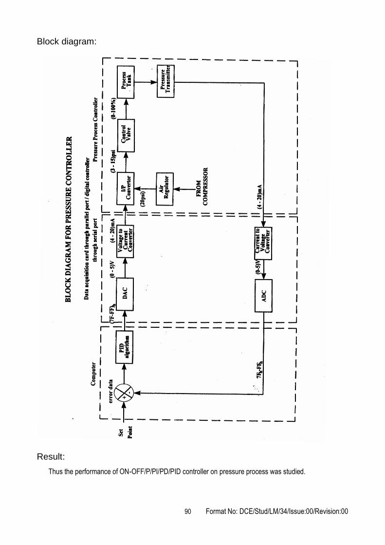
90 Format No: DCE/Stud/LM/34/Issue:00/Revision:00
Block diagram:
Result:
Thus the performance of ON-OFF/P/PI/PD/PID controller on pressure process was studied.
91 Format No: DCE/Stud/LM/34/Issue:00/Revision:00
Outcome:
From this experiment, students will be able to learn the types of control modes and the function of
elements in the closed loop control system.
Applications:
A PID (Proportional Integral Derivative) controller is a common instrument used in industrial control
applications. A PID controller can be used for regulation of speed, temperature, flow, pressure and
other process variables.
1. What are the types of controllers?
2. Define – PID Controller
3. Define – Derivative Gain
4. Define – Integral Gain
5. Define – Proportional Gain
6. Define – Reset Rate
7. What is meant by feed back?
8. What is the function of an ON/OFF controller?
9. What is the function of a proportional controller?
10. What is the function of a derivative controller?
11. What is the function of an integral controller?
12. Define – MRAC
13. Define – Proportional Band
14. What is meant by self tuning?
15. What is meant by error?
Viva - voce

92 Format No: DCE/Stud/LM/34/Issue:00/Revision:00

93 Format No: DCE/Stud/LM/34/Issue:00/Revision:00
Expt. No.47 HYDRAULIC SYMBOLS

94 Format No: DCE/Stud/LM/34/Issue:00/Revision:00

95 Format No: DCE/Stud/LM/34/Issue:00/Revision:00
Expt. No.48 PNEUMATIC SYMBOLS

96 Format No: DCE/Stud/LM/34/Issue:00/Revision:00

97 Format No: DCE/Stud/LM/34/Issue:00/Revision:00
ME6712 - MECHATRONICS LABORATORY
LIST OF PROJECTS
Automated Double Hacksaw
Design & Fabrication of Attachable Wheelchair Automator
Electromagnetic Braking System
Electronic assisted hydraulic braking system
Two Wheeler Automation with security System
Sensor Based Inspection Conveyor
Automatic drunken drive avoiding system for automobile
Automatic Solar Traffic and Street Light Controller
Automatic Wheel Chair for physically disabled person
Fabrication of Automatic jack