Embed Size (px)
Citation preview

on the European Directive 2010/75/EU IED Industrial Emissions Directiveunder the influence of the new European standards
GUIDANCE BOOK

2 | CO N T E N T

| 3
ON THE EUROPEAN DIRECTIVE2010/75/EU IEDINDUSTRIAL EMISSIONS DIRECTIVEUNDER THE INFLUENCE OF THE NEW EUROPEAN STANDARDS
DIRECTIVE 2010/75/EU OF 24TH NOVEMBER 2010 ON INDUSTRIAL EMISSIONS (INTEGRATED POLLUTION PREVENTION AND CONTROL) (IED)
EUROPEAN STANDARD EN 14181 STATIONARY SOURCE EMISSIONS – QUALIT Y ASSURANCE OF AUTOMATED MEASURING SYSTEMS
EUROPEAN STANDARD EN 15267 AIR QUALIT Y – CERTIFICATION OF AUTOMATED MEASURING SYSTEMS
NATIONWIDE PRACTICE FOR EMISSION MONITORING (23.1.2017)

4 | CO N T E N T
0 | C ONTENT

CO N T E N T | 5
CONTENT
1 | THE EUROPEAN DIRECTIVES 9European Directive 2010/75/EU on Industrial Emissions Directive (IED) 9 WID – Directive on the incineration of waste 10 Waste Incineration Directive requirements 10 Emission limit values for waste incineration plants (continuous measurements, standardized at 11 % O2, mineral waste oil at 3 % O2) 13 Emission limit values acc. to WID up to 40 % thermal co-incineration 13 CProc for combustion plants co-incinerating waste 14 Special cement plant regulation 17 LCPD – Directive 2001/80/EC on the limitation of emissions of certain pollutants into the air from large combustion plants 18 LCPD 2001/80/EC requirements 18 IED 2010/75/EU requirements for combustion plants 18 Emission limit values (mg/Nm3) for combustion plants using solid fuels 20 Emission limit values (mg/Nm3) for combustion plants using liquid fuels 22 Emission limit values (mg/Nm3) for combustion plants using gaseous fuels 24 Emission limit values (mg/Nm3) for combustion plants of gas turbines 26
and gas engines
2 | EN 14181 29EN 14181 – Quality assurance for automatic measuring equipment 30 QAL 1 – Testing the suitability of the equipment technology 30
QAL 2 – Installation/calibration testing 31 QAL 3 – Continuous monitoring 31 AST – Annual Surveillance Test 31
3 | EN 15267 33
4 | EMISSION DATA EVALUATION AND ASSESSMENT 37Validation 37Validity of the calibration curve 40Logging and documentation for verification 41 Classification (required by authority in Germany) 41European minimum requirements prEN 17255 42 Stationary source emissions – Quality assurance of AMS data 42 First Level Data (FLD) 45 Standardized First Level Data (SFLD) 45 Averaged first level data (AFLD) 45 Short-Term Average (STA) 45 Standardized Short-Term Average (SSTA) 45

6 | CO N T E N T
Validated Short-Term Average (VSTA) 45 Validated Long-Term Averages (VLTA) 46 QAL3 procedure 46 Calibration range check 46 Standardization of concentrations and flue gas flow data 46 Block averages 47 Rolling averages 47
5 | SYSTEM D-EMS 2020 AND D-EMS 2020 CS 49Basic system with the D-MS 500 KE communication unit 52Price effective compact system D-EMS 2020 CS for small and middle sized plants 54Overall system with all available software modules 56
6 | MEASURING DEVICES FOR EMISSIONS + AMBIENT AIR 59 D-R 290 – Dust and opacity monitor 59D-R 320 – Dust monitor 60D-R 808 – Dust monitor 61D-R 820 F – Extractive dust monitor for wet gases 64D-RX 250 – Combined probe 65F-701-20 – Environmental dust monitor 66HM-1400 TRX 2 – Total mercury analyzer 67D-FL 100 – Volume flow measuring system 68D-FL 220 – Volume flow measuring system 69
7 | GLOSSARY, DOWNLOADS + SOURCE REFERENCES 71
8 | SALES + SERVICE 75

| 7
PREFACE
This Guidance book contains legal obligations for plants according to directive 2010/75/EU of 24th November 2010 - as well as requirements for continuous emission- and evaluation systems.
Read the guidance book if you have any question to the latest limit values valid for your plant
When you search for information to EN 14181 – quality assurance for automated measuring systems (AMS)
If you like to research minimum requirementsLook up abbreviations within the glossaryUse links and source references for your own research and detailed informationAdditionally, you will find applications and a DURAG product overview at the end
of this guidance book
Since years, the DURAG GROUP is committed to optimize your day-to-day business with this guidance book. We are delighted about your interest.

8 | CO N T E N T
1 | THE EUROPEAN DIRECTIVES

T H E E U R O P E A N D I R E C T I V E S | 9
EUROPEAN DIRECTIVE 2010/75/EU ON INDUSTRIAL EMISSIONS (IED)
Directive 2010/75/EU of 24th November 2010 on the integrated pollution prevention and control
Integrated approach to avoid or minimize pol- luting emissions in the atmosphere, water and soil, as well as waste from industrial and agricultural installations, with the aim of achieving a high level of environmental and health protection.
The new, over 100 pages long IED recasts seven separate existing European Directives related to industrial emissions into a single Directive (including large combustion plants, incineration and co-incineration of waste, old IPPC Directive). The IED came into force on 6th January 2011 and was required to be transposed into national law by 7th January 2013. In Germany, the Ordinance on Large Combustions and Waste Incinerators was updated on 2nd May 2013. The IED replaces the above Directives with effect from 7th January 2014 and the LCP with effect from 1st January 2016.
The emission limit values were significantly reduced in particular for large combustion plants to the part and are structured as fol-lows:
Combustion plants using solid fuels (excluding gas turbines and gas engines)
Combustion plants using liquid fuels (excluding gas turbines and gas engines)
Combustion plants using gaseous fuels (excluding gas turbines and gas engines)
Gas turbines and gas engines
Industrial installations must use the best available techniques to achieve the highest general level of protection of the environ-ment as a whole, which are developed on a scale which allows implementation in the relevant industrial sector, under economical-ly and technically viable conditions. The Euro-pean Commission must adopt BAT conclusi-ons containing the emission levels associated with the BAT. These conclusions shall serve as a reference for the drawing up of permit con-ditions.
Please find in the subsequent tables the emis-sion limit values according to the directives 2000/76/EC and 2001/80/EC as well as the 2010/70/EU IED, origin www.euro-analytics.de, without any liability.
T H E E U R O P E A N D I R E C T I V E S

10 | T H E E U R O P E A N D I R E C T I V E S
WID – DIRECTIVES ON THE INCINERATION OF WASTE
The WID 2000/76/EC covered the incineration of hazardous and non-hazardous waste but excluded exemptions for vegetable waste, radioactive waste and animal carcasses. The Directive applies not only to facilities inten-ded for waste incineration (“dedicated inci-neration plants“) but also to “co-incineration“ plants (facilities whose main purpose is to produce energy or material products and which use waste as a regular or additional fuel, this waste being thermally treated for the purpose of disposal). The Directive did not cover experimental plants for improving the incineration process and which treat less than 50 tons of waste per year.
The Directive entered into force on 29th De-cember 2000. Transposition into national legislation was necessary by 28th December 2002. From this date on new incinerators had to comply with the provisions of the Directi-ve. The Directive 2000/76/EC was replaced by the new Directive on Industrial Emissions IED 2010/75/EU with effect from 4th January 2014.
Waste Incineration Directive requirementsEmission standards shall be regarded as ha-ving been complied with, if within one calen-dar year
All daily averages do not exceed the daily emission limit values set out in the tables below
Either all validated half-hourly averages do not exceed the half-hour limit values in co-lumn A
Or 97 % of the validated half-hourly aver-ages do not exceed the 97 % limit values in column B
For carbon monoxide (CO): 97 % of all daily averages of CO do not ex-
ceed 50 mg/Nm3 Either 95 % of all CO 10-minutes values
do not exceed 150 mg/Nm3 Or all CO half-hourly averages do not ex-
ceed 100 mg/Nm3, taken in any 24-hour pe-riod
The 10-minute average value of the tempe- rature in the post combustion zone has to be above 850 °C, or above 1100 °C if hazar-dous waste with a high halogen content is burnt
The half-hourly average values and the 10- minute averages shall be determined within the effective operating time (excluding the start-up and shut-off periods if no waste is being incinerated) from the measured va-lues after having subtracted the value of the confidence interval. The daily average values shall be determined from those vali-dated average values.

CO N T E N T | 11

12 | CO N T E N T
1 | THE EUROPEAN DIRECTIVES TABLES

T H E E U R O P E A N D I R E C T I V E S | 13
Emission limit values for waste incineration plants (continuous measurements, standardized at 11 % O2, mineral waste oil at 3 % O2), shown in mg/Nm3
Specials Daily Avg. WID 2000
1/2 h Avg. WID 2000 (100 %) <1/2 h-LV A
1/2 h Avg. WID 2000 (97 %) <1/2 h-LV B
Daily Avg. IED 2010
1/2 h Avg. WID 2000 (100 %) <1/2 h-LV A
1/2 h Avg. WID 2000 (97 %) <1/2 h-LV B
Dust 10 30 10 10 30 10
TOC 10 20 10 10 20 10
HCl 10 60 10 10 60 10
HF 1 4 2 1 4 2
SO2 50 200 50 50 200 50
NO2 ≤ 6 t/d existing plants 1)
200 not included 400 not included
> 6 t/d existing and all new plants
200 400 200 200 400 200
CO 50 100 2) 150 (95 % at 10 min) 2)
50 (97 %) 100 2) 150 (95 % at 10 min) 2)
Remarks: 1) Existing plant full requested for authorization before 28.12.2002
and put into operation not later than 28.12.20042) Alternatively
Emission limit values acc. to WID up to 40 % thermal co-incineration
Limit value calculation for solid, liquid and biological waste according to the following formula, if no specific limit value has been defined.
If waste incineration is the main purpose of a co-incineration plant it shall be treated as a normal incineration plant. If the heat release from the waste incineration is less than 10% of the total heat release it is set to equal 10 %.
CPROC * VPROC + CWASTE * VWASTE
VPROC + VWASTE = C

14 | T H E E U R O P E A N D I R E C T I V E S
CProc for combustion plants co-incinerating waste
Pollutant Plant specification EC Directive 2000/76 Waste incineration
EC Directive 2010/75 Industrial Emissions
Fuel Thermal input [MW]
CProc as daily avg. [mg/m3]
CProc as daily avg. [mg/m3] transitional ruling 1)
CProc as daily avg. [mg/m3] existing plants as of 01.01.2016 2)
CProc as daily avg. [mg/m3] new plants as of 07.01.2013 3)
Dust Solid fuels with the exception of biomass (O2 content 6 %)
< 50 50 50 50 50
50 to 100 50 50 30 20
100 to 300 30 30 25 (peat: 20) 20
> 300 30 30 20 10 (peat: 20)
Biomass (O2 content 6 %)
< 50 50 50 50 50
50 to 100 50 50 30 20
100 to 300 30 30 20 20
> 300 30 30 20 20
Liquid fuels (O2 content 3 %)
< 50 50 50 50 50
50 to 100 50 50 30 20
100 to 300 30 30 25 20
> 300 30 30 20 10

T H E E U R O P E A N D I R E C T I V E S | 15
SO2 Solid fuels with the exception of biomass (O2 content 6 %)
< 50 not included
not included
not included
not included
50 to 100 850 (SAG ≥ 90 %) 4)
850 400 (peat: 300)
400 (peat: 300)
100 to 300 850 to 200 (linear decrease) (SAG ≥ 92 %) 4)
200 200 200 (peat: 300, peat with fluidized bed 250)
> 300 200 (SAG ≥ 95 %) 4)
200 200 150 (fluidized bed partial 200)
Biomass (O2 content 6 %)
< 50 not included
not included
not included
not included
50 to 100 200 200 200 200
100 to 300 200 200 200 200
> 300 200 200 200 150
Liquid fuels (O2 content 3 %)
< 50 not included
not included
not included
not included
50 to 100 850 850 350 350
100 to 300 850 to 200 (linear)
400 to 200 (linear)
250 200
> 300 200 200 200 150
Pollutant Plant specification EC Directive 2000/76 Waste incineration
EC Directive 2010/75 Industrial Emissions
Fuel Thermal input [MW]
CProc as daily avg. [mg/m3]
CProc as daily avg. [mg/m3] transitional ruling 1)
CProc as daily avg. [mg/m3] existing plants as of 01.01.2016 2)
CProc as daily avg. [mg/m3] new plants as of 07.01.2013 3)
Continued on next page

16 | T H E E U R O P E A N D I R E C T I V E S
Pollutant Plant specification EC Directive 2000/76 Waste incineration
EC Directive 2010/75 Industrial emissions
Fuel Thermal input [MW]
CProc as daily avg. [mg/m3]
CProc as daily avg. [mg/m3] transitional ruling 1)
CProc as daily avg. [mg/m3] existing plants as of 01.01.2016 2)
CProc as daily avg. [mg/m3] new plants as of 07.01.2013 3)
NO2 Solid fuels with the exception of biomass (O2 content 6 %)
< 50 not included
not included not included not included
50 to 100 400 400 300 (lignite: 400)
300 (peat: 250)
100 to 300 300 200 200 200
> 300 200 200 200 150 (pulv. lignite: 200)
Biomass (O2 content 6 %)
< 50 not included
not included
not included
not included
50 to 100 350 350 300 250
100 to 300 300 300 250 200
> 300 300 200 200 150
Liquid fuels (O2 content 3 %)
< 50 not included
not included
not included
not included
50 to 100 400 400 400 300
100 to 300 300 200 200 150
> 300 200 200 150 100
Remarks: 1) For existing plants before 31.12.2015 and new plants before 07.01. 2013
(New/ existing plant definition see IED Article 30, paragraph 2 and 3)2) For existing plants as of 01.01.2016
(New/existing plant definition see IED Article 30, paragraph 2 and 3)3) For new plants as of 07.01.2013
(New/ existing plant definition see IED Article 30, paragraph 2 and 3)4) With indigenous fuels alternatively minimum rates of desulphurization (=SAG)
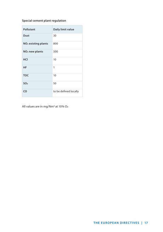
T H E E U R O P E A N D I R E C T I V E S | 17
Special cement plant regulation
Pollutant Daily limit value
Dust 30
NOx existing plants 800
NOx new plants 500
HCl 10
HF 1
TOC 10
SO2 50
CO to be defined locally
All values are in mg/Nm3 at 10 % O2

18 | T H E E U R O P E A N D I R E C T I V E S
LCPD – DIRECTIVE 2001/80/EC ON THE LIMITATION OF EMISSIONS OF CERTAIN POLLUTANTS INTO THE AIR FROM LARGE COMBUSTION PLANTS
The LCPD covered all combustion installati-ons with a rated thermal output exceeding 50 MW irrespective the type of fuel used with the exception of waste. The Directive shall apply only to combustion plants designed for pro-duction of energy with the exception of tho-se which make direct use of the products of combustion in manufacturing processes.
“existing plants”: licensed before 1st July 1987 will have to com- ply with the emission limit values in annex A of the Directive latest 1st January 2008 (ex-ception: no more than 20,000 operational hours after 1st January 2008 ending no later than 31st December 2015).
“new plants”: licensed after 1st July 1987 but before 27 th No- vember 2002, in operation 27 th November 2003 latest will have to comply with the emis-sion limit values in annex A of the Directive.
“new new plants”:licensed after 27 th November 2002 or in ope-ration later than 27 th November 2003 will have to comply with the limit values of part B of the Directive.
National, more stringent time and emission limit values possible.
LCPD 2001/80/EC RequirementsEmission standards shall be regarded as ha-ving been complied with, if within one calen-dar year
Existing plants, starting 1st January 2008, new plants until 2002/2003:None of the calendar monthly mean value
exceeds the emission value A97 % of all 48 hourly SO2 and dust mean va-
lues do not exceed 110 % of emission limit values A
95 % of all 48 hourly NOX mean values do not exceed 110 % of emission values A
New plants, later than 2002/2003:No validated daily average value exceeds
the relevant limit values B95 % of all the validated hourly averages
values do not exceed 200 % of the relevant limit values B
Continuous measurement for SO2, NOX and dust required for plants > 100 MW.
IED 2010/75/EU Requirements for Combustion PlantsThe Directive on Industrial Emissions IED 2010/75/EC has replaced the LCPD 2001/80/EC with effect from 1st January 2016.
“existing plants”: permitted before 7 th January 2013 and put in- to operation not later than 7 th January 2014.
“new plants”: permitted after 7 th January 2013 or in opera-tion later than 7 th January 2014.
Emission standards shall be regarded as ha-ving been complied with if the evaluation of the measurement results indicates, for ope-rating hours within a calendar year, that all of the following conditions have been metno validated monthly average value ex-
ceeds the relevant emission limit values set out in the tables below
no validated daily average value exceeds 110 % of the relevant emission limit values set out in the tables below
95 % of all the validated hourly average va-lues over the year do not exceed 200 % of the relevant emission limit values set out in the tables below

G E S E T Z L I C H E B E S T I M M U N G E N | 19

2 0 | T H E E U R O P E A N D I R E C T I V E S
Thermal input and fuel LCPD 2001
Limit values LCPD 2001 existing plants 1)
Limit values LCPD 2001 new plants 2)
Thermal input and fuel IED 2010
Limit values IED existing plants 3)
Limit values IED new plants 4)
SO2 < 50 MW not included
25–50 MW in preparation
50–100 MW
in general 2000 850 50–100 MW
in general 400 400
Biomass 2000 200 Biomass 200 200
Peat 300 300
100–500 MW 2000 to 400 linear decrease
200 100–300 MW
in general 250 200
Biomass 200 200
Peat 300 300
> 500 MW 400 200 > 300 MW in general 200 150
Fluidized bed
200 200
NO2 < 50 MW not included 25–50 MW in preparation
50–100 MW 600 400 50–100 MW
in general 300 300
Lignite 450 400
Biomass, peat
300 250
100–300 MW
in general 600 200 100–300 MW
in general 200 200
Biomass 300 Biomass, peat
250 200
300–500 MW 600 200
> 500 MW
before 2015
500 200 > 300 MW in general 200 150
after 2016 200 Lignite 200 200
Emission limit values (mg/Nm3) for combustion plants using solid fuels with the exception of gas turbines and gas engines, standardized at 6 % O2

T H E E U R O P E A N D I R E C T I V E S | 21
Thermal input and fuel LCPD 2001
Limit values LCPD 2001 existing plants 1)
Limit values LCPD 2001 new plants 2)
Thermal input and fuel IED 2010
Limit values IED existing plants 3)
Limit values IED new plants 4)
Dust < 50 MW not included
25–50 MW in preparation
50–100 MW 100 50 50–100 MW 30 20
100–500 MW 100 30 100–300 MW
in general 25 20
Biomass, peat
20
> 500 MW 50 30 > 300 MW in general 20 10
Biomass, peat
20 20
Remarks: 1) New and existing plants acc. to LCPD, article 4 paragraph 1 or 32) New plants acc. to LCPD, article 4 paragraph 23) Existing plants acc. to IED, article 30 paragraph 2:
Permitted before 07.01.2013 and put into operation not later than 07.01.2014 (derogations up to 2016)
4) New plants acc. to IED, article 30 paragraph 3: All plants except paragraph 2

2 2 | T H E E U R O P E A N D I R E C T I V E S
Emission limit values (mg/Nm3) for combustion plants using liquid fuels with the exception of gas turbines and gas engines, standardized at 3 % O2
Thermal input and fuel LCPD 2001
Limit values LCPD 2001 existing plants 1)
Limit values LCPD 2001 new plants 2)
Thermal input and fuel IED 2010
Limit values IED existing plants 3)
Limit values IED new plants 4)
SO2 < 50 MW not included 25–50 MW in preparation
50 - 100 MW 1700 850 50–100 MW 350 350
100–300 MW
1700 400 to 200 linear decrease
100–300 MW 250 200
300–500 MW
1700 to 400 linear decrease
200
> 500 MW 400 200 > 300 MW 200 150
< 50 MW not included 25–50 MW in preparation
NO2 50–100 MW 450 400 50–100 MW 450 300
100–300 MW
in general 450 200 100–300 MW
in general 200 150
Biomass 300 Refineries 450
300–500 MW
others 150 100
300–500 MW 450 200 Refineries 450
> 500 MW 400 200 > 500 MW 150 100
< 50 MW not included 25–50 MW in preparation

T H E E U R O P E A N D I R E C T I V E S | 2 3
Remarks: 1) New and existing plants acc. to LCPD, article 4 paragraph 1 or 32) New plants acc. to LCPD, article 4 paragraph 23) Existing plants acc. to IED, article 30 paragraph 2:
Permitted before 07.01.2013 and put into operation not later than 07.01.2014 (derogations up to 2016)
4) New plants acc. to IED, article 30 paragraph 3: All plants except paragraph 2
Thermal input and fuel LCPD 2001
Limit values LCPD 2001 existing plants 1)
Limit values LCPD 2001 new plants 2)
Thermal input and fuel IED 2010
Limit values IED existing plants 3)
Limit values IED new plants 4)
Dust 50–100 MW 50 50 50–100 MW
in general 30 20
Refineries 50
100–500 MW 50 30 100–300 MW
in general 25 20
Refineries 50
> 500 MW 50 30 > 300 MW in general 20 10
Refineries 50

24 | T H E E U R O P E A N D I R E C T I V E S
Thermal input and fuel LCPD 2001
Limit values LCPD 2001 existing plants 1)
Limit values LCPD 2001 new plants 2)
Thermal input and fuel IED 2010
Limit values IED existing plants 3)
Limit values IED new plants 4)
SO2 < 50 MW not included
25–50 MW in preparation
> 50 MW in general 35 > 50 MW in general 35
Liquefied gas
5 Liquefied gas
5
coke oven gas
800 400 coke oven gas
400
blast furnace gas
800 200 blast furnace gas
200
gases from the gasifica-tion of refinery residues
800
< 50 MW not included 25–50 MW in preparation
Emission limit values (mg/Nm3) for combustion plants using gaseous fuels with the exception of gas turbines and gas engines, standardized at 3 % O2

T H E E U R O P E A N D I R E C T I V E S | 2 5
Remarks: 1) New and existing plants acc. to LCPD, article 4 paragraph 1 or 32) New plants acc. to LCPD, article 4 paragraph 23) Existing plants acc. to IED, article 30 paragraph 2:
Permitted before 07.01.2013 and put into operation not later than 07.01.2014 (derogations up to 2016)
4) New plants acc. to IED, article 30 paragraph 3: All plants except paragraph 2
Thermal input and fuel LCPD 2001
Limit values LCPD 2001 existing plants 1)
Limit values LCPD 2001 new plants 2)
Thermal input and fuel IED 2010
Limit values IED existing plants 3)
Limit values IED new plants 4)
NO2 50–100 MW
Natural gas
not specified
150 50–100 MW
Natural gas
100 100
in general 300 200 Steel industry gas
200
Refineries 200
100–300 MW
Natural gas
not specified
150 100–300 MW
Natural gas
100 100
in general 300 200 Steel industry gas
200
Refineries 200300–500 MW
Natural gas
not spe-cified
150
in general 300 200
> 500 MW
Natural gas
not specified
100 > 300 MW Natural gas
100 100
in general 200 200 Steel industry gas
200
Refineries 200
< 50 MW not included 25–50 MW in preparation
Dust > 50 MW in general 5 5 > 50 MW in general 5
blast furnace gas
10 10 blast furnace gas
10
Steel industry gas
50 30 Steel industry gas
30
CO > 50 MW no defaults > 50 MW Natural gas 100

26 | T H E E U R O P E A N D I R E C T I V E S
Thermal input and fuel LCPD 2001
Limit values LCPD 2001 existing plants 1)
Limit values LCPD 2001 new plants 2)
Thermal input and fuel IED 2010
Limit values IED existing plants 3)
Limit values IED new plants 4)
SO2 < 50 MW not included
25–50 MW in preparation
50–100 MW not included
50–100 MW not included
NO2 < 50 MW not included
25–50 MW in preparation
> 50 MW Gas turbi-nes, liquid fuels (light and medium distillate)
120 > 50 MW Liquid fuels (light and medium distillate)
90 50
Gas turbines, natural gas
50 Natural gas
50 50
Gas turbines, other gaseous fuels
120 Other gaseous fuels
120 50
Gas engine
120 75
Emission limit values (mg/Nm3) for combustion plants of gas turbines and gas enginesstandardized at 15 % O2

T H E E U R O P E A N D I R E C T I V E S | 27
Remarks: 1) New and existing plants acc. to LCPD, article 4 paragraph 1 or 32) New plants acc. to LCPD, article 4 paragraph 23) Existing plants acc. to IED, article 30 paragraph 2:
Permitted before 07.01.2013 and put into operation not later than 07.01.2014 (derogations up to 2016)
4) New plants acc. to IED, article 30 paragraph 3: All plants except paragraph 2
Thermal input and fuel LCPD 2001
Limit values LCPD 2001 existing plants 1)
Limit values LCPD 2001 new plants 2)
Thermal input and fuel IED 2010
Limit values IED existing plants 3)
Limit values IED new plants 4)
Dust < 50 MW not included
25–50 MW in preparation
> 50 MW not included
50–100 MW
CO > 50 MW no defaults > 50 MW Gas turbi-nes, liquid fuels (light and medium distillate)
100
Gas turbines, natural gas
100
Gas engine
100

2 8 | CO N T E N T
2 | EN 14181

E N 14181 | 29
EN 14181
The stated European Directives stipulate in the annexes on measurement technology that sampling and analysis of all pollutants is to be carried out in accordance with CEN standards. The associated CEN standard was compiled by the technical committee CEN/TC 264 ”Air Quality”. The EN 14181 was approved by CEN on 3rd November 2003 and officially released in July 2004; it has been updated by 30th November 2014. Appendix K of EN 14181:2014 describes the main technical changes between the first and second edition of the standard.
EN 14181 defines three quality assurance levels (QAL) and an annual surveillance test (AST) for automated measuring systems (AMS):
QAL 1 Requirement for use of automatic measuring equipment that has had its suitability tested (the test complies with EN ISO 14956)
QAL 2Installation of automatic measuring equip-ment (AMS), calibration of AMS using the standard reference measuring method (SRM), determination of measuring uncertainty/va-riability of AMS and check for observance of preset measuring uncertainties
QAL 3Continuous quality assurance by the operator (drift and precision of the AMS, verification on control card)
ASTAnnual surveillance test including SRM mea-surements to check the uncertainty of the AMS values.
EN 15267-3
EN 15259
AMS
periodically periodically periodically
installation
QAL
1QAL
2
functionaltest
functionaltest
functionaltest
functionaltest
1 year
3–5 years
major plant change
ASTQAL
3QAL
3QAL
2QAL
3QAL
3ASTQAL
3QAL
3

3 0 | E N 14181
EN 14181 prescribes which characteristics automated measuring systems AMS must possess, and how they must be calibrated and maintained. In addition to the calibra-tion function, the measuring uncertainty – which plays a decisive role in the validati-on of the measured values obtained during continuous monitoring – is also determined from the data of the calibration experiment. In addition, the requirements for the uncer-tainty of the measured values obtained with the measuring equipment, which are defined in the EU directives relating to fossil power plants, waste incineration plants and waste co-incineration plants, are checked using a method described in the standard.
All new installed automated measuring system AMS must be certified against the standards EN 15267 and must at least allow a lowest cer-tified measuring range of 1.5 times the emis-sion limit value ELV for waste (co-)incinerators or 2.5 times the ELV for large combustion plants.The validated average value is defined as the value calculated from the standardized and referenced average value by subtracting the standard deviation (standard uncertainty) at the daily limit value of the standardized va-lues determined by calibration in accordance with EN 14181.
EN 14181 – QUALITY ASSURANCE FOR AUTOMATIC MEASURING EQUIPMENT
Influenced by: VDI 2066/3950 ISO 10155 North American (RATA) requirements
Prerequisites: Suitable measuring instruments Comparable measuring instruments Error-free installation Permanent quality assurance during
plant operation
QAL 1 – Testing the suitability of the equipment technologyQAL 1 specifies the suitability of a measuring instrument by calculating the total measuring uncertainty in accordance with EN ISO 14956 prior to installation
Standard deviation Linearity deviation Reproducibility Drift Temperature dependence Operating voltage effects
TÜV suitability test Cross sensitivities Response behavior Response times Measuring instrument type

E N 14181 | 31
Device QAL 1 Total Expanded Uncertainty Uc=uc.1.96
QAL 2 Total Allowed Uncertainty Percentage of Daily Limit Value
Availability Requirement > 95 %
D-R 290 0.52 mg/m3 30 99.4 %
D-R 320 0.35 mg/m3 30 97.5 %
D-R 808 0.3 mg/m3 30 99.3 %
D-R 820 F 1.23 mg/m3 30 98.2 %
D-RX 250 2.8 mg/m3 30 99.6 %
QAL 1 values of selected DURAG GROUP devices:
QAL 2 – Installation/calibration testingSelection of the measuring location
(measuring site report)Correct installation of the measuring
instrumentCorrect selection of the measuring rangeCalibration of the device using a standard
reference method, min. 15 measuring points distributed over 8–10 hours on 3 days
Determination of the calibration curve or curves under different operating conditi-ons (fuels, load, etc.) without manipulation of the furnace or filter systems (adjusting the burner, slitting the filter hoses or redu-cing the capacity of the electrostatic preci-pitator)
Calibration curve either as linear regression or straight line from the zero point to the center of a point cluster
Calculation of the fluctuation range as s atthe 95 % confidence interval
Test repeated at least every 5 years and more frequently if so required by legislation or authority (e. g. 3 years for the WID).
QAL 3 – Continuous monitoringPermanent quality assurance during plant
operation through the operating personnelAssurance of reliable and correct operation
of the measuring instrument (maintenance records)
Regular checks, at least once per mainte- nance interval
Zero point, measuring range, drift Determination of drift and accuracy using
CUSUM cards or with an Excel chart Identification/definition of when manufac-
turer’s maintenance is necessary for the measuring instrument.
AST – Annual Surveillance TestAnnual confirmation of the QAL 2 calibration curveVerification of the validity of the calibration curve Function test Small calibration using 5 parallel measurements QAL 2 is to be repeated if AST failsResetting of the exceedance counter for the invalid calibration range.

32 | CO N T E N T
3 | EN 15267

15267 | 33
EN 15267
An automated measuring system AMS to be used at installations shall have been proven suitable for its measuring task in accordance with EN 15267. Using this standard, it shall be proven that the total uncertainty of the results obtained from the AMS meet the spe-cification for uncertainty stated in the appli-cable regulations. The standard EN 15267 is divided into
Part 1: General principlesPart 2: Initial and yearly repeated
assessment of the manufacturer’s quality system for design and manufacturing
Part 3: Performance criteria and test procedures
The standard defines a modified implemen-tation of the approval test, such as contacting the test institute, clarification of the range of applications and the announcement of the test at the LAI (German federal ambient air protection working party).
After successfully carrying out an extensive laboratory and a three months field test, the test report will be evaluated in the context of a technical examination moderated by the German EPA. With positive assessment, the certificate is issued by the German EPA for a period of five years and published in addition to the Federal Gazette on the website www.qal1.de as suitable instrument.
The quality management system and the pro-duction of the manufacturer have to undergo an initial and yearly repeated audit in addition to the standard EN ISO 9001 audit.
During the annual audits, inevitably necessa-ry changes of the hardware and/or software of the measuring systems are reviewed and confirmed by further research, if necessary. The manufacturer has to record all performed modifications in a technical logbook. The modifications are divided into the following categories:
Type 0: No measurable influence on the measuring system
Type 1: No significant influence Type 2: Significant influence, a partial or
total review by the test institute may be necessary

3 4 | E N 15267
See below the minimum requirements for continuously measuring systems from the lab (L) or field test (F):
Performance characteristic Performance criteria specific to AMS Tests
Dust Hg Volume Flow
Laboratory Field test
Response time ≤ 200 s ≤ 200 s ≤ 60 s L + F
Repeatability standard deviation at zero point
≤ 2,0 % a) ≤ 2,0 % a) ≤ 2,0 % a) L
Repeatability standard deviation at span point
≤ 5,0 % b) ≤ 2,0 % a) L
Lack-of-fit ≤ 3,0 % a) ≤ 2,0 % a) ≤ 3,0 % a) c) L + F
Influence of ambient temperature change from nominal value at 2 °C within specified range at zero point
≤ 5,0 % a) ≤ 5,0 % a) ≤ 5,0 % a) L
Influence of ambient temperature ch-ange from nominal value at 20 °C within specified range at span point
≤ 5,0 % a) ≤ 5,0 % a) ≤ 5,0 % a) L
Influence of sample gas pressure at span point, for a pressure change Δp of 3 kPa
≤ 2,0 % a) L
Influence of sample gas flow on extractive AMS for a given specification by the manufacturer
≤ 2,0 % a) L
Influence of voltage, at –15 % below and at +10 % above nominal supply voltage
≤ 2,0 % a) ≤ 2,0 % a) ≤ 2,0 % a) L
Influence of vibration ≤ 2,0 % a) L
Cross-sensitivity ≤ 4,0 % a) L

E N 15267 | 35
Performance characteristic Performance criteria specific to AMS Tests
Dust Hg Volume Flow
Laboratory Field test
Excursion of the measurement beam of in-situ AMS
≤ 2,0 % a) L
Determination coefficient of calibration function, R2
≥ 0,90 d) ≥ 0,90 ≥ 0,90 F
Minimum maintenance interval 8 days 8 days 8 days F
Zero drift within maintenance interval ≤ 3,0 % a) ≤ 3,0 % a) ≤ 2,0 % a) F
Span drift within maintenance interval ≤ 3,0 % a) ≤ 3,0 % a) ≤ 4,0 % a) F
Availability ≥ 95,0 % ≥ 95,0 % ≥ 95,0 % F
Reproducibility, Rfield ≤ 2,0 % a) (> 20mg/m3) ≤ 3,3 % a) (≤ 20mg/m3)
≤ 3,3 % a) ≤ 3,3 % a) F
a) Percentage value as percentage of the upper limit of the certification rangeb) Percentage value as percentage of the emission limit valuec) Only for laboratory testsd) Currently under verification

36 | CO N T E N T
4 | EMISSION DATA EVALUATION AND ASSESSMENT

E M I S S I O N D ATA E VA L U AT I O N A N D A S S E S S M E N T | 37
The evaluation of the continuously acquired emission values must comply with the rele-vant legal requirements, fulfill the require-ments of the competent authority and provi-de the operator with the possibility of having the historical, current and predicted emission values for reporting, conducting evaluations and controlling the operational process of the plant.
Essential evaluation criteria include:Continuous acquisition of the parameters
and reference values to be measuredGeneration of standardized,
oxygen referenced integral values (10 min, 30 min, 60 min)
Validation of the integral values (absolute, percentage)
Generation of daily average values (48 h average values, monthly average values) from the validated integral values
Monitoring of the equipment failure (maintenance/fault) and logging in the daily and annual statistics
Monitoring of the valid calibration ranges and evaluation/logging in accordance with EN 14181
Monitoring of drift and precision of the continuously operating analyzers (control charts) in accordance with EN 14181.
VALIDATION
The (half-) hourly average value is validated at the end of the integration interval from the integral values of the raw measurement data by subtracting the measurement uncertain-ty as a constant value, derived from the cali-bration (at 95 % confidence interval) after the appropriate standardization (temperature, pressure) and oxygen reference value calcula-tion, from the measurement value. Negatively validated average values will be set to zero.
The daily average values are formed as the arithmetic mean of the validated (half-) hourly average values.
EMISSION DATA EVALUATION AND ASSESSMENT

3 8 | E M I S S I O N D ATA E VA L U AT I O N A N D A S S E S S M E N T
15,57 mg/Nm3
15,57 mg/Nm3
24:00 ∑1n
n
1
Kval
15,57 mg/Nm3
Validierung de Validierung en
10 mg/m3
STAUB
Integration 30 min
Integration 30 min
Integration 30 min
8 Vol-% 400 K 1100 hPa 100.000 m3/h
17,3 mg/Nm3
16,3 mg/Nm324:00
Massenstrom 1,73 kg/h
16 mg/Nm3
–1 mg/Nm3
K = 10 x x x x21–O2B
21–8M = 100.000 x 10-6 x 17,3
RUNDUNG
RUNDUNG
100100–10
1103,251100
400273
∑1n
n
1
Kval
O2 TEMPERATUR
Integration 30 min
Integration 30 min
Integration 30 min
DRUCK FEUCHTE VOLUMEN-STROM
Validierung (QAL2)
10 Vol-%
16 mg/Nm3
10 mg/m3
DUST
Integration 30 min
Integration 30 min
Integration 30 min
8 Vol-% 400 K 1100 hPa 100.000 m3/h
17,3 mg/Nm3
–10 % Validation
K = 10 x x x x21–O2B
21–8M = 100.000 x 10-6 x 17,3100
100–101013,251100
400273,15
O2 TEMPERATURE
Integration 30 min
Integration 30 min
Integration 30 min
PRESSURE HUMIDITY FLOW
10 Vol-%
VALIDATION
The integral values will be validated by subtraction of the confidence interval at 95 %. The daily averages will be calculated from the validated integral values.
PROTOCOLS
Concentration:Minute valuesIntegral values (e. g. 60‘)24-h average value48-h average valueWeekly average valueMonthly average valueYearly average value
Mass flow (Totals/averages):Minute valuesIntegral values24-h value48-h valueWeekly average valueMonthly average valueYearly average value
Statistic:Limit values (Percentile)Time of operationTime out of operationSystem Availability (Analyzers,
evaluation system)

E M I S S I O N D ATA E VA L U AT I O N A N D A S S E S S M E N T | 39
As requirements, IED 2010/75/EU, stipulate maximum values of measurement uncertain-ty for continuous measuring equipment and the validation of the measurement results. Until now, confidence and tolerance ranges of at least 5 or 10 % were defined for measure-ment uncertainty. These confidence and tole-rance ranges are now inapplicable.
The validated (half-) hourly and daily average values are determined on the basis of measu-red (half-) hourly average values after subtrac-tion of the confidence interval determined by calibration (measurement uncertainty/varia-bility).
The value of the 95 % confidence interval for an individual measurement result must not exceed the following percentages of this emission limit stipulated for the daily average value:
carbon monoxide 10 % total organic carbon 30 %
sulphur dioxide 20 % mercury 40 %
nitrogenoxide 20 % hydrogen chloride 40 %
total dust 30 % hydrogen fluoride 40 %

4 0 | E M I S S I O N D ATA E VA L U AT I O N A N D A S S E S S M E N T
mg/
m 10
9
8
7
6
5
4
3
2
1
00 2 4 6 8 10 12 14 16 18 20 mA
validcalibrationrange
1,1* Ŷs, max
Ŷs, max
0,2* TGW
D-R 320
VALIDITY OF THE CALIBRATION CURVE
Determination of the calibration curve for the measuring instrument using a standard refe-rence method under diff erent operating con-ditions (fuels, load, etc.) without manipulati-on of the furnace or fi lter systems (adjusting the burner, slitting the fi lter hoses or reducing the capacity of the electrostatic precipitator).
Calibration of the measuring instrument using a minimum of 15 measuring points dis-tributed over 8–10 hours on 3 days. The long period should take all possible aspects of pro-per operation of the plant into account. The validity range for the calibration is specifi ed in the calibration report.
Validated average values outside the valid calibration range (No. 6.5 EN 14181) are to be stored with the associated time and with their status and are to be logged at the end of the day and year. In the short period class, the percentage exceedance of the valid calibra-tion range in the current week (Mo.–Su.) are registered and the number of weeks with ex-cessive percentages is registered in the long period class.
Calibration function only valid within the calibration range
Valid calibration range between 0 and Ŷs,max plus an extension of 10 % of Ŷs, max or to 20 % of ELV, whichever is greater
New calibration QAL2 necessary within six months if
> 5 % of all values per week lie above the va-lid calibration range for more than 5 weeks or > 40 % of all values lie above the valid calibration range for at least one week
Extrapolation of higher values permitted

E M I S S I O N D ATA E VA L U AT I O N A N D A S S E S S M E N T | 41
LOGGING AND DOCUMENTATION FOR VERIFICATION
Daily reports with all integral values incl. status information
Monthly reports with all daily average va-lues (48 h average values) incl. status infor-mation.
Annual reports with all monthly average va-lues incl. status information
Statistics reports with information on limit value exceedances, availability of the AMS, failure of waste gas cleaning equipment and the emitted emission quantity
Documentation of failure of AMS for the operator’s information
CUSUM, Shewhart or EWMA card to verify drift and precision of the AMS at the zero point and reference point
Complete documentation of the AMS by the operator in accordance with Point 9 An-nex C of EN 14181
Correct and legally conformant evaluation/ reporting of continuous measurement and calculation data is no longer possible ma-nually. Modern computer-based evaluation systems are indispensable for fulfilling the specific requirements. These systems are pre-programmed according to the plant type; they acquire, calculate and report all emis-sion-relevant data according to the legal re-quirements as well as the specifications of the local authorities.
A special form of evaluation is prescribed in Ger-many and can also be activated to expand the EU standard evaluation.
Classification (required by authority in Germany)Although all integral values are stored along with the plant and channel status, the prin-ciple of classification is still maintained. Classi-fication documents the class frequency dis- tribution for the whole year on a single page in a clearly identifiable way. Limit value ex-ceedances with reference to pollutants are identifiable at a glance. Classification must be referenced to a time starting at 00:00. As an al-ternative to issuing classification tables, the integral values determined can also be issued as daily, monthly and annual tables.
The daily average values are to be determined for the interval from 00:00 to 24:00 if there are at least 12 valid half-hourly average values are available.
Every day is declared invalid, in which more than 5 half-hourly average values (WID) or 3 hourly average values (LCPD) are unavailab-le due to faults or maintenance of the conti-nuous measurement system. If more than 10 days a year are declared invalid for such rea-sons, the competent authority must oblige the operator to introduce suitable measures to improve the reliability of the continuous monitoring system.

42 | E M I S S I O N D ATA E VA L U AT I O N A N D A S S E S S M E N T
Draft of March 2014:European Minimum Requirements for Data Acquisition and Handling Systems (DAHS)This European Standard specifies require-ments for the handling of data produced by an AMS. The main items covered by the stan-dard are given by, but not limited to raw da-ta acquisition, raw data validation, data cor-rection, data averaging, data security, data alarms, data archiving, data display, data ac-cess, program validation, data reporting and program integrity.
It specifies the minimum requirements for the handling of AMS data, supporting the re-quirements of EN 14181 and legislation e.g. EU Directives such as IED. The standard does not preclude the use of additional features and functions provided the minimum require-ments of this standard are met and that these features do not adversely affect data quality, clarity or access.The scope of this standard begins at the final data output terminals of the AMS and covers the entire process leading to and including the presentation of data to the competent authority.
Raw data received in analogue format (4–20 mA) or as digital communication (e. g. Mod-bus, Profibus, OPC) from any AMS or PEMS output shall be continuously sampled at a rate fast enough to ensure no loss in information.
EUROPEAN MINIMUM REQUIREMENTS PREN 17255 (DRAFT)
Stationary source emissions – Quality assurance of AMS data

CO N T E N T | 43

4 4 | E M I S S I O N D ATA E VA L U AT I O N A N D A S S E S S M E N T
The sampling can, never be slower than 1 sample per 10 seconds from each individual source (each individual AMS, typically 1 se-cond sampling rate).
FLD: First Level Data, raw data including status signals or average values calculated from the raw data including status signals. Sampling rate not slower than 1 per 10 se-conds. Storage in DAHS for at least 5 year in an auditable manner.
SFLD: Standardised first level data. First level emission data calibrated and normalized using first level peripheral data (these values are not for reporting, but for information of the operator)
AFLD: Averaged first level data, calculated for the STA averaging time from all valid FLD values
STA: Short Term Averages (typically 10, 30, 60 minutes) are calculated from first level data if 2/3 or more FLD-values are available. Verification, that STA is within the calibrati-on range (EN14181 QAL 2). Storage in DAHS at least 5 years in an auditable manner.
SSTA: Standardised short-term average. Short-term average of emission data cali- brated and converted to standard condi-tions using short-term average peripheral data
VSTA: Validated short-term average.Standardised short-term average with the relevant confidence interval subtracted to comply with EU Directive reporting require-ments
VLTA: Validated Long Term Average (typically daily, 48-hourly, weekly, monthly, yearly). The averages are calculated from validated short-term averages. Valid if ¼ or more VSTA-values are available, storage in DAHS at least 5 years in an auditable manner.
Depending on the regulations, averages can be calculated as block averages and/or rolling averages

E M I S S I O N D ATA E VA L U AT I O N A N D A S S E S S M E N T | 45
First Level Data (FLD)The FLD values are the first set of data to be stored in permanent storage. Data in the FLD-storage can be identical to the raw data, i.e. unprocessed as they are received from the AMS or PEMS, or they can be scaled to units representing concentration or process para-meters.
Standardised first level data (SFLD)The SFLD is determined by applying the cali-bration function and the conversion to stan-dard conditions directly to the FLD. This pro-vides a short time period data set, which can be used by the operator for process/abate-ment control or optimization. The DAHS shall make it clear that averaging these SFLD over the STA period could give a different answer to the SSTA and shall not be used for com-pliance assessment.
Averaged first level data (AFLD)The average first level data shall be calculated for the STA averaging time from all valid FLD values. Negative FLD values shall be included in the calculation of the averaged FLD. If the FLD value is an average of raw data the FLD average has to be calculated from the FLD values weighted by the time co-verage of each FLD value.
Short-Term Average (STA)Short-term averages are the shortest period of averages the plant shall report to the authorities. According to variations in diffe-rent EU Directives this can be 10 minutes, 30 minutes or 1 hour, depending on the type and application of the plant. The calibration function determined in QAL2 according to EN 14181 shall be used to calculate the short-term averages (STA) on the basis of the aver-aged FLD.The STA shall be evaluated if valid FLD is avai- lable for at least two-thirds of the STA aver-aging time. The DAHS shall automatically log and report monthly the amount of time where exceedance of the measurement range has taken place, and the total time where data has been capped may not exceed 2 % of the total operation time in each individual calen-dar month.
Standardises short term averages (SSTA)The SSTA is calculated by normalizing the STA emission values with STA peripheral values, such like oxygen, temperature, pressure and moisture.
Validated short-term average (VSTA)The validated STA (VSTA) shall be calculated by subtracting the uncertainty from the stan-dardized STA in accordance with the proce-dure laid down in the national legislation.
NOTE: The EU Directives prescribe that, before reporting the concentration of any pollu- tant to the authorities, the measurement uncertainties in the form of 95 % confidence intervals shall be subtracted from the measu-rement value, for compliance reporting only. Different countries have different interpreta-tion of this, and consequently different proce-dures of doing it. The method of subtracting and the value of the uncertainty shall be sta-ted in the report and stored in the event log.

4 6 | E M I S S I O N D ATA E VA L U AT I O N A N D A S S E S S M E N T
Validated Long Term Averages (VLTA)Long-term averages are any longer periods of averages the plant shall report to the autho- rities. According to variations in different EU Directives the averaging period can be 1 day, 1 week, 1 month, 1 quarter or 1 year, depen-ding on the type and application of the plant.
The long-term average is calculated as the arithmetic mean of sufficient numbers of vali-dated short-term averages (VSTA), to make up the period of the long-term average.
If the plant operator shall report according to legal local time (LLT), the daily average shall be calculated as follows: for the day switching from LST to DST, whe-re one hour is lost, the daily average shall be calculated from the STA values within the 23 h time period; for the day switching from DST to LST, where one hour is gained (duplicated), the daily average shall be calculated from the STA values within the 25-h time period.
QAL3 procedureThe QAL3 procedure should be performed in the DAHS, the necessary input data (measure-ment at zero and span point) shall either be automatically or manually entered into the DAHS. The DAHS reporting shall include all data related to the entire QAL3 process.
Calibration range checkVerification that the STA-measurement is within the calibration range as specified du-ring the last valid QAL2 according to EN 14181.
Standardization of concentrations and flue gas flow dataMeasured concentrations shall be standar-dised only as SSTA-values (typically 10, 30, 60 minutes) since SSTA values are the only values validated by a calibration according to QAL2 procedure from EN14181. Standardization can include:
Correction to reference oxygen levelsCorrection for temperatureCorrection for pressureCorrection for water vapor
The SSTA-value of the pollutant mass flow shall be calculated from SSTA-values of the concentration and the flue gas flow at same conditions. The annual emission is calcu- lated by summation of the SSTA-values of the pollutant mass flow.
Flue gas flows are for instance used for the calculation of the pollutant mass flow for reporting to the authority or calculation of the emission limit value in cases that two or more combustion plants are connected to one stack.

E M I S S I O N D ATA E VA L U AT I O N A N D A S S E S S M E N T | 47
Block averagesWhere averages are ‘block‘ type averages, periods will commence as detailed below
Averaging period Starting time (unless otherwise specified by local legislation or permit)
Calculation basis
≤ 1 min for FLD Minute averages start at the first second of the minute. Averages less than 1 min start at the first second of the minute and subsequent intervals, e. g. for a 5 s period at 0 s, 5 s, 10 s, 15 s etc.
Raw data
≤ 1 h for STA Hourly averages start at the first minute of the hour. Averages less than 1 h start at the first minute of the hour and subsequent intervals, e.g. for a 10 min period at 0 min, 10 min, 20 min etc.
FLD
1-day Daily averages start at 00:00:00 LLT of the day. VSTA
48 h 48-h-averages start at 00:00:00 LLT on the first day of the calendar year and then every second day.
VSTA
1 month Monthly averages start at 00:00:00 LLT on the first day of the calendar month.
VSTA
1 year Annual averages start at 00:00:00 LLT on the first day of the calendar year
VSTA
Rolling averagesWhere averages are rolling averages, the average commences N periods prior to the actual moment in time that the period ends and has a resolution indicated in the table below. For example, for 10 min rolling averages, a value is recorded every minute that represents the average of the previous ten 1-min-averages.
Averaging period Calculation frequency (unless otherwise specified by local legislation or permit)
Calculation basis (unless otherwise specified by local legislation or permit)
Multiples of periods less than 1 h, i. e. 10 min
every FLD period FLD
1 h every FLD period FLD
1 day every STA period VSTA
48 h every STA period VSTA
1 month daily VSTA
1 year monthly VSTA

5 | SYSTEM D-EMS 2020 AND D-EMS 2020 CS

SYSTEME D-EMS 2020 UND D-EMS 2020 CS
A modular system applicable for plants of any size
QAL1 certified according to EN 15267-2 by the TÜV Rheinland
Software available in 20 languages
Emission evaluation in accordance with Ger-man requirements, the European Directive 2010/75/EU (IED), considering EN 14181:2014 and European Minimum Requirements prEN 17255.
The D-EMS 2020 system can be freely confi-gured according to the needs of the plant and the requirements of the operator. The system is modular structured, fulfills the current re-quirements, is prepared for future guidelines and can be easily extended after installation by further software modules as well as hard-ware components.The heart of the D-EMS 2020 system is the Ser- ver PC in an industrial design with the suita-bility tested D-EMS 2020 software. The use of server hard disks as Raid array network ensure a high level of reliability and, in conjunction with the D-MS 500 KE/FC data logger, enables compliance with the legally required availa-bility of 99 %.
The system can be composed of:
The D-MS 500 KE/FC data loggerThe D-MS 500 FC DIN railsA bus connection directly to the PC or via
the D-MS 500 KE/FCD-EMS 2020 CS as closed network compa-
tible emission evaluator or data acquisition unit both with value visualization at site
Or a combination of the above options
If the D-MS 500 KE/FC is used, there is inter-mediate data storage for up to 128 days. If the connection to the PC or the PC itself is faulty, after re-establishing communication all data are automatically calculated, stored in the sy-stem in the correct chronological order, the official reports created and remote emission monitoring transmission automatically exe-cuted without downtime.
S Y S T E M D - E M S 2 02 0 A N D D - E M S 2 02 0 C S | 49

5 0 | S Y S T E M D - E M S 2 02 0 A N D D - E M S 2 02 0 C S
DE | 2020
EN | 2020
D-MS 500 KE / FC
4–20 mA, Modbus,PROFIBUS, OPC UA, Elan…
RING-SPEICHER6 JAHRE
D-EMS 2020 CS
RING-SPEICHER32 TAGE
4–20 mA, Modbus,PROFIBUS, OPC UA, Elan…
BEHÖRDE
EFÜ
WWW
PI-SYSTEMESCADASPS ANALYSATORPLS HANDEINGABE
RING MEMORY 6 YEARS
RAIDSYSTEM
D-EMS 2020Environmental + Process
Data Management SystemD-EMS 2020 CLIENTS
AUTHORITY WWW
D-MS 500 KE/FC
4–20 mA, Modbus,PROFIBUS, OPC UA, Elan…
RING MEMORY 6 YEARS
D-EMS 2020 CS RING
MEMORY 32 DAYS
4–20 mA, Modbus,PROFIBUS, OPC UA, Elan…
PI/HISTORIANSSCADAPLC ANALYZERDCS MANUAL ENTRY
RING-SPEICHER6 JAHRE
RAIDSYSTEM
DCF77 GPS
D-EMS 2020
D-EMS 2020 CLIENTS
BACKUP AUF EXT. MEDIUM Z. B.: SERVER / NAS
Umwelt- + ProzessdatenManagement System
RADIO CLOCK
BACKUP ON EXT. MEDIUM
E. G.: SERVER / NAS

S Y S T E M D - E M S 2 02 0 A N D D - E M S 2 02 0 C S | 51
DE | 2020
EN | 2020
D-MS 500 KE / FC
4–20 mA, Modbus,PROFIBUS, OPC UA, Elan…
RING-SPEICHER6 JAHRE
D-EMS 2020 CS
RING-SPEICHER32 TAGE
4–20 mA, Modbus,PROFIBUS, OPC UA, Elan…
BEHÖRDE
EFÜ
WWW
PI-SYSTEMESCADASPS ANALYSATORPLS HANDEINGABE
RING MEMORY 6 YEARS
RAIDSYSTEM
D-EMS 2020Environmental + Process
Data Management SystemD-EMS 2020 CLIENTS
AUTHORITY WWW
D-MS 500 KE/FC
4–20 mA, Modbus,PROFIBUS, OPC UA, Elan…
RING MEMORY 6 YEARS
D-EMS 2020 CS RING
MEMORY 32 DAYS
4–20 mA, Modbus,PROFIBUS, OPC UA, Elan…
PI/HISTORIANSSCADAPLC ANALYZERDCS MANUAL ENTRY
RING-SPEICHER6 JAHRE
RAIDSYSTEM
DCF77 GPS
D-EMS 2020
D-EMS 2020 CLIENTS
BACKUP AUF EXT. MEDIUM Z. B.: SERVER / NAS
Umwelt- + ProzessdatenManagement System
RADIO CLOCK
BACKUP ON EXT. MEDIUM
E. G.: SERVER / NAS

52 | S Y S T E M D - E M S 2 02 0 A N D D - E M S 2 02 0 C S
BASIC SYSTEM WITH THE D-MS 500 KE COMMUNICATION UNIT
D-EMS 2020 Server Windows-based and certified D-EMS 2020
software19" or Tower PC in industrial designWindows 8.1/10 Pro or Windows Server
2012 R2/2016
D-MS 500 KE data logger with ring memory19“/3HU housing3x serial (RS-232 or RS-485)1 service interface RS-232 for PC (laptop),
hyper terminal1 Ethernet TCP / IP interfaceInternal ring memory 32 days
(optional 64/96/128 days)Operating voltage
24V DC, 100W (Single or redundant) or 115/230 VAC, 50/60 Hz, 100 VA
In case of failure of the Server PC or interrup-tion of the communication the raw data will be buffered after restoration of the inter- ruption all data sets will be automatically restored.
alternatively:D-MS 500 FC data logger with ring memory DIN / top hat rail mounting design1 serial interface RS232/4852 Ethernet RJ45 interfacesInternal ring memory 32 days,
(optional 64/96/128 days)Operating voltage 24V DC,
100W (single or redundant)
In case of failure of the Server PC or interrup-tion of the communication the raw data will be buffered after restoration of the inter-ruption all data sets will be automatically restored.

S Y S T E M D - E M S 2 02 0 A N D D - E M S 2 02 0 C S | 53
RING-MEMORY32 DAYS
RINGMEMORY6 YEARS
RAIDSYSTEM
DCF77 GPS
GRAPHICSPRINTER
BACKUP ON EXT. MEDIUM E. G.: SERVER / NAS
CONTROL ROOM
ENVIRONMENTALDEPT.
MANAGEMENT
D-MS 500 KE / FCData logger unit
D-EMS 2020Server
BOILER
FGC
DUST, SO2, CO, O2, T
4–20 mAbinary
MODBUSPro�bus
ELAN
MODBUSTCP/IP
TCP/IPOPC UA
Data network
D-EMS 2020 REDExternal redundant
Data Storage System

5 4 | S Y S T E M D - E M S 2 02 0 A N D D - E M S 2 02 0 C S
PRICE EFFECTIVE COMPACT SYSTEM FOR SMALL AND MIDDLE-SIZED PLANTS
D-EMS 2020 CSCompact system,
no additional evaluation PC required19”/ 3HU housingWindows 8.1 / 10 Pro operating system3x serial (RS-232 or RS-485)1 Ethernet interface
2 USB InterfacesRadio/GPS controlled clockModern solid-state disk technology
instead of hard disksOperating voltage 24V DC, 100W
(Single or redundant) or 115/230 VAC, 50/60 Hz, 100 VA

S Y S T E M D - E M S 2 02 0 A N D D - E M S 2 02 0 C S | 55
DCF77 GPS
GRAPHICSPRINTER
BACKUPON EXT. MEDIUM
E.G.: SERVER / NAS
D-EMS 2020 REDExternal redundant
Data Storage System
D-EMS 2020 CS
BOILER
FGC
DUST, SO2, CO, O2, T
4–20 mAbinary
MODBUSPro�bus
ELANTCP/IP
OPC UA

5 6 | S Y S T E M D - E M S 2 02 0 A N D D - E M S 2 02 0 C S
OVERALL SYSTEM WITH ALL AVAILABLE SOFTWARE MODULES
D-EMS 2020 EFÜ Module for emission data transmission to the authority in accordance with the German national interface definition and using the Internet (EFÜ.www).
D-EMS 2020 Web Module for HTML-based presentation of selected values and reports on a web server in the Inter- / Intranet.
D-EMS 2020 RWS Electronic acquisition and display of raw values, sampling rate 1/s, 12-bit accuracy.
D-EMS 2020 RED External, physically separated, redundant data storage on a NAS.
D-EMS 2020 QAL 3 Module for complete documentation of the AMS, acquisition and evaluation of drift / precision (QAL3) according to EN 14181:2014, with automatic creation of the CUSUM, Shewhart or EWMA control chart.
D-EMS 2020 MDE Manual data entry module for any pre-set / discontinuous values.
D-EMS 2020 AMS Control Free configuration tool of flow controls: Zero or test gas supply for automatic AMS calibration, back purging of sample gas pipes / Pitot probes and others. Various valve controls incl. automatically / manual control options.
D-EMS 2020 GHG Module for collection, evaluation, reporting und visualization of current and historical GHG output of fossil-fired combustion plants according to the European Greenhouse gas emission allowance trading scheme (2003/87/EG).
D-EMS 2020 Cloud SSL secured access to measured and calculated data and reports on the internet from everywhere.
D-EMS 2020 Water Software module for acquisition, evaluation and long-term storage of water, waste water and / or rain water for quality control and calculation of quantities (also for verification of authority) with calculation of water loads incl. daily, monthly and yearly reports.
D-EMS 2020 Calc Engineering tool for recalculation of results after changes / adaptions of evaluation regulations and / or measured values.
DATACEMS Predictive Emissions Monitoring System Module (PEMS) – Determination of current emissions based on historical emission data and current plant / process parameters.


5 8 | S Y S T E M E D - E M S 2 02 0
6 | MEASURING DEVICES FOR EMISSIONS + AMBIENT AIR

MEASURING DEVICES FOR EMISSIONS + AMBIENT AIR
D-R 290 | DUST AND OPACITY MONITOR
M E A S U R I N G D E V I C E S F O R E M I S S I O N S + A M B I E N T A I R | 59
Continuous and contactless measurementIdeal for medium to large dust concentrationsAutomatic zero and reference point checkAutomatic contamination check and correctionQAL1 certified according to EN 15267
Measuring value Dust concentration, opacity
Measuring range Dust: 0 … 80 mg/m3 … 0 … 4000 mg/m3Opacity: 0 … 20 % … 0 … 100 %
Smallest certified measuring range 0 … 15 mg/m3
Flue gas temperature up to 250 °C standard, others on request
Flue gas relative humidity 0 … 95 % RH, non-condensing
Inner duct pressure –50 … +20 hPa
Stack/duct inner diameter Measurement path: 1 … 18 m
Ambient temperature –40 … +60 °C

6 0 | M E A S U R I N G D E V I C E S F O R E M I S S I O N S + A M B I E N T A I R
Continuous and contactless measurementIdeal for small to medium dust concentrationsOne-sided installation without optical alignmentAutomatic zero and reference point check Automatic contamination check and correctionQAL1 certified according to EN 15267
Measuring value Dust concentration
Measuring range 0 … 5 mg/m3 … 0 … 200 mg/m3
Smallest certified measuring range 0 … 7.5 mg/m3
Flue gas temperature up to +600 °C
Flue gas relative humidity 0 … 95 % RH, non-condensing
Inner duct pressure –50 … +50 hPa
Stack/duct inner diameter > 0.7 m
Ambient temperature –40 … +60 °C
D-R 320 | DUST MONITOR

M E A S U R I N G D E V I C E S F O R E M I S S I O N S + A M B I E N T A I R | 61
Continuous measurementIdeal for small to medium dust concentrationsOne-sided installation without optical alignmentAutomatic zero and reference point check Automatic contamination check and correctionQAL1 certified according to EN 15267
Measuring value Dust concentration
Measuring range 0 … 5 mg/m3 … 0 … 200 mg/m3
Smallest certified measuring range 0 … 7.5 mg/m3
Flue gas temperature up to +350 °C
Flue gas relative humidity 0 … 95 % RH, non-condensing
Inner duct pressure –50 … +50 hPa
Stack/duct inner diameter > 0.3 m
Ambient temperature –40 … +60 °C
D-R 808 | DUST MONITOR

62 | G L O S S A R Y + D O W N L O A D S

G L O S S A R Y + D O W N L O A D S | 63

6 4 | M E A S U R I N G D E V I C E S F O R E M I S S I O N S + A M B I E N T A I R
Continuous measurement of dust concentration in wet gasesIdeal for small to medium dust concentrationsExtractive measurement, dilution of the sampleAutomatic zero and reference point check Automatic contamination check and correctionQAL1 certified according to EN 15267
Measuring value Dust concentration
Measuring range 0 … 15 … 0 … 200 mg/m3
Smallest certified measuring range 0 … 15 mg/m3
Flue gas temperature up to +220 °C
Flue gas relative humidity 0 … ≥ 100 % RH, max. 30 g/m3 H2O as aerosol
Inner duct pressure –30 … +2 hPa
Stack/duct inner diameter > 0.4 m
Ambient temperature –20 … +50 °C
D-R 820 F | EXTRACTIVE DUST MONITOR FOR WET GASES

M E A S U R I N G D E V I C E S F O R E M I S S I O N S + A M B I E N T A I R | 65
One probe for simultaneous measurement of dust concentration, volume flow, temperature and absolute pressure
Only one probe / mounting hole in the exhaust ductCompact designNo moving partsAutomatic zero and reference point check
D-RX 250 | COMBINED PROBE
Measuring values Dust concentration, flow velocity, absolute pressure, temperature
Measuring range Dust: 0 … 15 mg/m3 0 … 500 mg/m3Flow velocity: 3 … 35 m/sAbsolute pressure: 800 … 1300 hPaTemperature: 0 … 200 °C, optional 0 … 350 °C
Smallest certified measuring range Dust: 0 … 15 mg/m3Flow velocity: 3 … 30 m/s
Flue gas temperature up to 200 °C, optional up to 350 °C
Flue gas relative humidity 20 … 80 % RH, non-condensing
Inner duct pressure –100 … +200 hPa
Stack/duct inner diameter > 0.3 m
Ambient temperature –20 … +50 °C

6 6 | M E A S U R I N G D E V I C E S F O R E M I S S I O N S + A M B I E N T A I R
Continuous measurement of low dust concentrations in ambient air of low dust concentrations for PM2.5 or PM10
Multiple filter sampling for up to 1.5 years of operation with one filter bandExtended Gesytec protocol for improved remote operation and access
to measured data Precalibrated measuring system delivers accurate results without
specific local calibrationEasy integration into existing monitoring networks
Measuring value Dust concentration in ambient air PM2.5, PM10, TSP
Dust concentration 0 … 100 µg/m³ … 0 … 100 mg/m³
Certified measuring ranges PM2.5: 0 … 1000 µg/m3PM10: 0 … 200 µg/m3
Ambient air pressure 800 hPa … 1300 hPa
Ambient temperature Device: 0 … +40 °CSample inlet: –20 °C … +50 °C
F-701-20 | ENVIRONMENTAL DUST MONITOR

M E A S U R I N G D E V I C E S F O R E M I S S I O N S + A M B I E N T A I R | 67
Continuous mercury measurementMeasuring principle allows specification of elemental and oxidized mercuryAutomatic reference point check with internal HgCl2 calibration gas generator No extremely heated components, easy to maintainQAL1 certified accoring to EN 15267
Measuring value Total mercury concentration
Measuring range 0 … 15 … 0 … 400 μg/m3
Smallest certified measuring range 0 … 15 μg/m3 *
Flue gas temperature up to +300 °C
Flue gas relative humidity 0 … 100 % RF
Inner duct pressure (gauge) –50 … +20 hPa
Stack/duct inner diameter > 0,5 m
Ambient temperature Analyser: +5 … +50 °C ** Probe: –20 … +50 °C
HM-1400 TRX 2 | TOTAL MERCURY ANALYSER
* for large combustion plants** QAL1 certified: +5 ... +40 °C

6 8 | M E A S U R I N G D E V I C E S F O R E M I S S I O N S + A M B I E N T A I R
Continuous measurement of flow velocityVersions for use at extreme high temperatures or in corrosive gases availableOne-sided or installation on both sides possible Cost effective measurement systemRepresentative measurement even at difficult flow conditionsQAL1 certified according to EN 15267
Measuring value Flow velocity, volume flow
Measuring range Flow velocity: 3 … 50 m/s
Certified measuring ranges 3 … 30 m/s, 3 … 50 m/s
Flue gas temperature up to +450 °C, others on request
Flue gas relative humidity 0 … 95 % RH, non-condensing
Inner duct pressure –50 … +50 hPa
Stack/duct inner diameter 0,5 … 10 m
Ambient temperature –20 … +50 °C
D-FL 100 | VOLUME FLOW MEASURING SYSTEM

M E A S U R I N G D E V I C E S F O R E M I S S I O N S + A M B I E N T A I R | 69
Continuous and contactless measurementCorrosion resistant ultrasonic transducer Ideal for saturated or aggressive flue gasesAutomatic zero and reference point check Representative measurement even at difficult flow conditions QAL1 certified according to EN 15267
Measuring value Flow velocity, volume flow
Measuring range Flow velocity: 0 … 40 m/s
Certified measuring ranges 0 … 30 m/s
Flue gas temperature up to +300 °C
Flue gas relative humidity 0 … 100 % RH, condensation allowed
Inner duct pressure –50 … +20 hPa
Stack/duct inner diameter 0,5 … 13 m, dependant on flue gas and installation conditions
Ambient temperature –20 … +50 °C
D-FL 220 | VOLUME FLOW MEASURING SYSTEM

70 | CO N T E N T
7 | GLOSSARY,
DOWNLOADS +
SOURCE REFERENCES

G L O S S A R Y, D O W N L O A D S + S O U R C E R E F E R E N C E S | 71
GLOSSARY
AFLD Averaged First Level Data
AM Approval Methodology
AMS Automated Measuring System
AST Annual Surveillance Test
BAT Best Available Techniques
BImSchV Ordinance for the Implementation of the Federal Emission Control Act German: Verordnung zur Durchführung des Bundes-Immissionsschutzgesetzes
CDM Clean Development Mechanism
CEN European Committee for Standardization French: Comité Européen de Normalization
CER Certified Emission Reduction
CUSUM Cumulative Sum control card
DAHS Data Acquisition and Handling Systems
ELV Emission Limit Value
EN 14181 Stationary source emissions – Quality assurance of automated measuring systems
EN 14956 Air quality – Evaluation of the suitability of a measurement method by compari-son with a stated measurement uncertainty
EN 15267 Air quality – Certification of automated measuring systems, part 1–3
pr EN 17255 Stationary source emissions – Data acquisition and handling systems
EPA Environmental Protection Agency
FLD First Level Data
IED Industrial Emissions Directive 2010/75/EU of the European Parliament and of the Council of 24.10.2010 on industrial emissions (integrated pollution prevention and control)
ISO International Organization for Standardization
ISO 10155 Stationary source emissions – Automated monitoring of mass concentrations of particles - Performance characteristics, test methods and specifications
Continued on next page

72 | G L O S S A R Y, D O W N L O A D S + S O U R C E R E F E R E N C E S
GLOSSARY
JI Joint Implementation
LCPD Large Combustion Plant Directive 2001/80/EC of the European Parliament and of the Council of 23.10.2001 on the limitation of emissions of certain pollutants into the air from large combustion plants
LV Limit Value
MCERTS Monitoring Certification Scheme
QAL Quality Assurance Level
RATA Relative Accuracy Test Audit - US EPA
SAG Desulphurization rateGerman: Schwefelabscheidegrad
SFLD Standardized First Level Data
SRM Standard Reference Method
SSTA Standardized Short-Term Average
STA Short-Term Average
TI Air Technical Instructions on Air Quality ControlGerman: Technische Anleitung zur Reinhaltung der Luft TA Luft
TOC Total Organic Carbon (bitte mit einfügen nach TI Air)
TPCZ Temperature in the Post Combustion Zone
TÜV Technical Inspections OrganizationGerman: Technischer Uberwachungsverein
VDI The Association of German EngineersGerman: Verband Deutscher Ingenieures
VLTA Validated Long-Term Average
VSTA Validated Short-Term Average
WID Waste Incineration Directive 2000/76/EC of the European Parliament and of the Council of 04.12.2000 on the incineration of waste

G L O S S A R Y, D O W N L O A D S + S O U R C E R E F E R E N C E S | 73
DOWNLOADS + SOURCE REFERENCES
AM 00xx http://cdm.unfccc.int/methodologies/index.html
CDM projects http://cdm.unfccc.int/Projects/projsearch.html
EN 15267 https://www.beuth.de/en/norm/din-en-15267-1/112519055
EN 14181 https://www.beuth.de/en/norm/din-en-14181/207503732
EN 14956 https://www.beuth.de/en/norm/din-en-14956/81611061
ISO 10155 https://www.beuth.de/en/norm/iso-10155/1692306
LCPD 2001/80/EC http://eur-lex.europa.eu/LexUriServ/ LexUriServ.do?uri=OJ:L:2001:309:0001:0021:EN:PDF
Minimum Requirements
http://www.umweltbundesamt.de/sites/default/files/medien/ pdfs/Uniform-Practice-Emission-Monitoring.pdf
TI Air http://www.bmu.de/files/pdfs/allgemein/application/pdf/taluft.pdf
VDI 2066 http://www.vdi.eu/engineering/vdi-standards/
VDI 3950 http://www.vdi.eu/engineering/vdi-standards/
WID 2000/76/EC http://eur-lex.europa.eu/LexUriServ/ LexUriServ.do?uri=OJ:L:2000:332:0091:0111:EN:PDF
IED 2010/75/EU http://eur-lex.europa.eu/LexUriServ/ LexUriServ.do?uri=OJ:L:2010:334:0017:0119:EN:PDF

74 | CO N T E N T
8 | SALES + SERVICE

S A L E S + S E R V I C E | 75
SALES + SERVICE
DURAG Sales + Service GmbH & Co. KG Kollaustraße 10522453 Hamburg, Germany Tel. +49 40 55 42 18-0Fax +49 40 58 41 [email protected]
DURAG Branch East Halsbrücker Straße 34 09599 Freiberg, Germany Tel. +49 3731 30 04-0 Fax +49 3731 30 04-22 [email protected]
DURAG Branch North Kollaustraße 105 22453 Hamburg, Germany Tel. +49 40 55 42 18-0 Fax +49 40 58 41 54 [email protected]
DURAG Branch South Weidenweg 16 73087 Bad Boll, Germany Tel. +49 7164 912 25-0 Fax +49 7164 912 25-50 [email protected]
DURAG Branch West An der Pönt 53a 40885 Ratingen, Germany Tel. +49 2102 74 00-0 Fax +49 2102 74 00 28 [email protected]
DURAG SIENADURAG Siena do Brasil LtdaRua Vinte e Dois de Agosto, 66 Diadema - SP 09941-530 Brazil Tel. +55 11 4071-5050 r.28 Fax +55 11 4077-1718 [email protected]
DURAG France S. a. r. l. 147 avenue Paul Doumer92500 Rueil Malmaison, France Tel. +33 1 41 29 04 60 Fax +33 1 41 29 04 68 [email protected]
DURAG Inc. 1355 Mendota Heights Road Suite 200 Mendota Heights MN 55120, USA Tel. +1 651 451-1710 Fax +1 651 457-7684Toll Fee: 800 811 98 52 [email protected]
DURAG Inc. (Houston Branch)440 Cobia DriveSuite 1104 (building #11)Katy, TX 77494Tel. +1 832 437 3173Fax +1 832 437 8272 Toll Fee: 800 811 98 52 [email protected]
DURAG India Instrumentation Private Limited #27/30, 2nd Main Road Industrial Town, Rajajinagar Bengaluru 560 044, India Tel. +91 80 2314 5626, 2301 1700 Fax +91 80 2314 5627 [email protected]
DURAG Instrumentation (Shanghai) Co., Ltd. Room 706, Dibao Plaza, No. 3998 Hongxin Rd., Minhang District Shanghai, 201103 PR China Tel. +86 21 60732979-200 Fax +86 21 [email protected]
DURAG Italia S. r. l. Via Carlo Panseri, 118 CIM uffici, P. secondo 28100 Novara, Italy Tel. +39 0321 679569 Fax +39 0321 474165 [email protected]
DURAG Japan Office c/o TMS Planning Inc. 291-2 Umena, Mishima-shi Shizuoka-ken 411-0816 Japan Tel. +81 55 977 3994 Fax +81 55 977 3994 [email protected]
DURAG Korea Office RM #1131, Manhattan Building, 36-2, Yeouido-Dong, Yeongdeungpo-Gu, Seoul, Korea Tel. +82 2 761 8970 Fax +82 2 761 8971 [email protected]
DURAG Middle East Rep. OfficeOffice Number LB1905075th Floor, Jafza View 19Jebel Ali Free ZoneTel. +971 488683-30Dubai, United Arab [email protected]
DURAG SEA Pte. Ltd. 25 International Business Park #4–06 German Centre Singapore [email protected]
DURAG UK GmbHBretby Business Park, Ashby RoadBurton-on-Trent, Staffordshire DE15 0YZ, Great Britain Tel. +44 1283 553 481 Fax +44 1283 553 482 [email protected]

© D
URA
G G
ROU
P 09
/201
8 |
Su
bjec
t to
chan
ge w
itho
ut n
otic
e
DURAG GROUP
Kollaustraße 105 22453 Hamburg, Germany Telephone +49 40 55 42 18-0Fax +49 40 58 41 [email protected]
www.durag.com