Embed Size (px)
Citation preview
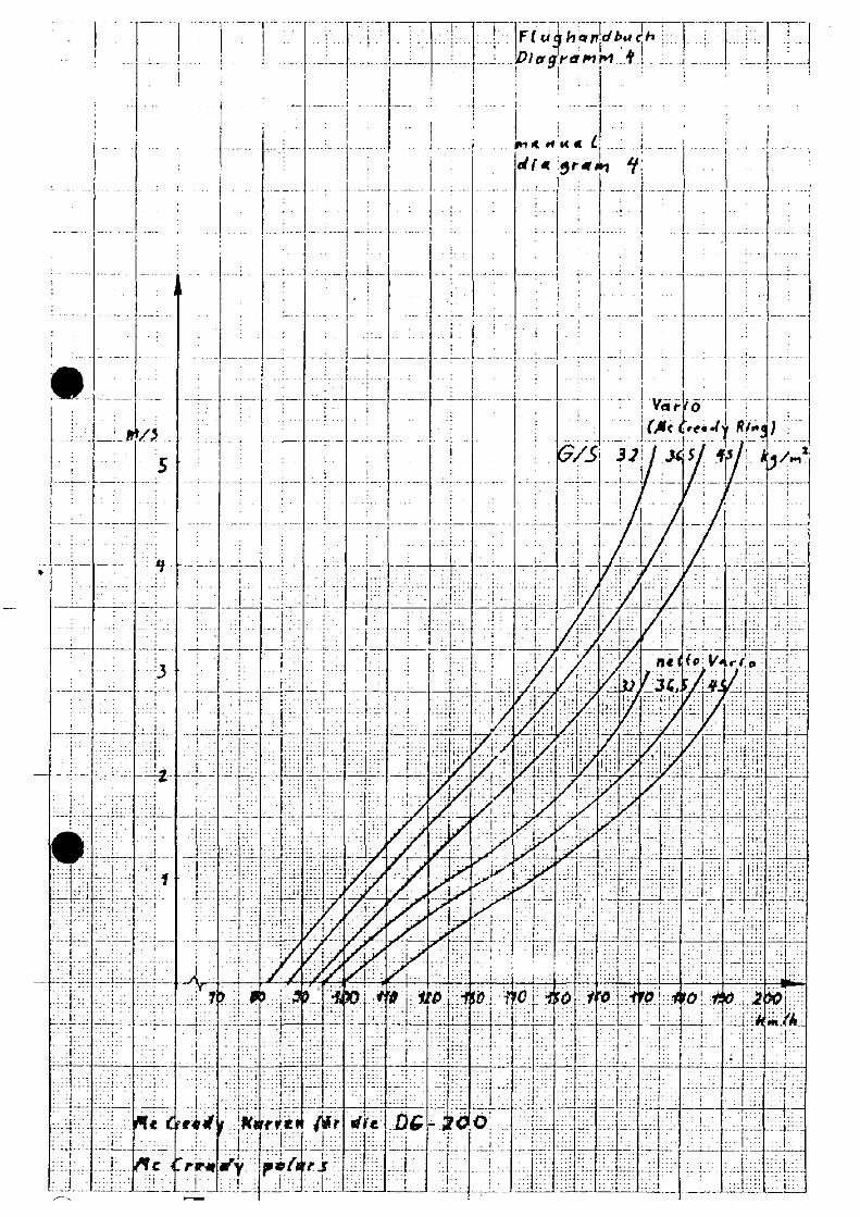
DG200 15m/17m
DG 202
Flight Manual
!"#$%&'()%%% *!"#$%&'()%%%%
!+ $&+ , - +


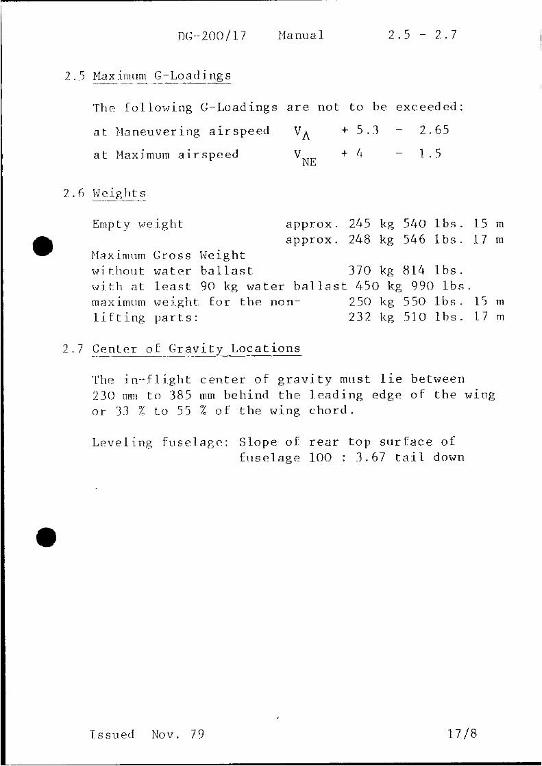


DG-200 Manual 5.1
5. Assembly and disassembly
5.1 Assembly
1. Open the canopy and open the access cover with a screwdriver.
2. Clean and lube the pins, bushings and the ball ends of the
control rod quick connects.
3. With a helper on the wingtip, lead the wings into place. Sight
thru the wing main pin bushings to determine alignment. Push
the main pins in as far as possible. Turn the handles up to the
fuselage wall. Therefore pull out the white securing knob. Set
the knob back in its locking position. The wing flaps connect
automatically. The best method for rigging is to set the flap
handle on 0o and to hold the flap in the 0
o position.
4. Connect aileron and spoiler controls. Spoilers are best
connected in the closed but not locked position. To check the
quick connects, insure that the sliding latch has returned as far
as it can locking the ball end in place.
The hole must be visibly. It is recommended to fit a diameter 1
mm spring pin in the hole (500 30 771)
disconnected
connected
hole for spring pin
Attach the cover plate.
5. Rigging of the stabilizer with the automatic elevator control self
connection mechanism. Set the trim nose
down. Set the stabiliser on, so that
the ball bearing at the fuselage side
push road is inserted into the funnel funnel
at the elevator. Look through the plexi-
glas disc to watch the procedure. When
stabilizer is set down laying on the fin
push it back. The ball bearing will slide ball
forward in the funnel if you will hold bearing
the elevator in the pertinent position. Use
an 8 mm wrench (supplied with your glider)
to tighten the front mounting bolt. Turn it
so that the securing spring engages into the slit of the bolt.
6. Control check………. Check tire pressures (3 bar 42 psi main,
2 bar 28 psi tailwheel). Check instruments.
Issued Sept. 1980 22


DG200 15m/17m
DG 202
FLIGHT INSTRUMENTS
DG Flugzeugbau GmbH
!"#$%&'()%%%*!"#$%&'()%%%%!+ $&+ , - +


DG200 15m/17m
DG 202
FLIGHT INSTRUMENTS
DG Flugzeugbau GmbH
!"#$%&'()%%%*!"#$%&'()%%%%!+ $&+ , - +


Edition 01.2007 Page 1 of 16
BOHLI COMPASS 46--MFK--1
Description page 2
Installation page 10
Manual Compass 46--MFK--1BOHLI MAGNETTECHNIK AG
Edition 01.2007Page 2 of 16
Description
Bohli compass for aerial navigation
A device, using the magnetic field of the earth for directional orientation, has been known inChina as far back as 2000 B.C. It originally consisted of a magnetic iron splinter, floating ontop of a small piece ofwood in awater container. Addedwasaminiature human figure pointingSouth with an outstretched arm.
Similar designs ofwater compasseswere used right into theMiddle Age. Theywere improvedfor more accurate reading by painting a compass--rose onto the floating wooden disc and bycentering the same with a pin. This type of instrument was known to all seagoing people.
In the 15th to 16thCentury a different type of compassbecame known,which hada “cap” (dab)that supported the magnetic needle on top of a pointed metal pin. The low center of gravityheld the needlemore of less horizontally; any remaining pitch, due to themagnetic inclination,was counter--balanced with weight. This principle, which uses the horizontal component ofthe earth’smagnetic field, has undergonemany refinements. It iswidely used in aviation com-passes today (Lit. 1. 2).
Unfortunately, this simple instrument fails during turns.Unless the axis of the needle is alignedperfectly vertical to the earth, it will start to swing. In a turn, when heading East or West, theneedle does point correctly. But as soon as the aircraft turns towards South or North, theneedle will be influenced by the magnetic inclination and will run ahead or behind, dependingon the direction of turn. If the angle of bank exceeds 15°, the compass needle goes berserk.Any directional information is lost. The pilot has to fly on a straight heading for some time inorder to allow the compass to calmdown.Only thencan he take a reading and initiate a furthercorrection toward the desired heading, using very little bank (Lit. 3, 4, 5, 6).
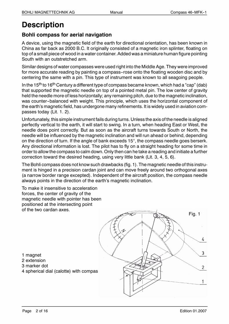
TheBohli compassdoesnot knowsuchdrawbacks (fig. 1). Themagnetic needle of this instru-ment is hinged in a precision cardan joint and can move freely around two orthogonal axes(a narrow border range excepted). Independent of the aircraft position, the compass needlealways points in the direction of the earth’s magnetic inclination.
To make it insensitive to accelerationforces, the center of gravity of themagnetic needle with pointer has beenpositioned at the intersecting pointof the two cardan axes.
1 magnet2 extension3 marker dot4 spherical dial (calotte) with compass rose
Fig. 1

Manual Compass 46--MFK--1BOHLI MAGNETTECHNIK AG
Edition 01.2007 Page 3 of 16
The inclination varies with geographic latitude. Over the magnetic poles the needle wouldpoint down vertically; on the magnetic equator it would lie horizontally. One can notice thiseffect on long flights going North--South or vice--versa.
The effect shows on the Bohli compass in thismanner: the imaginary circle, which the pointermark describes on the dial during a circle on the plane, becomes wider in lower latitudes andnarrower in higher latitudes. At a given inclination (latitude), the diameter of the imaginarycircle (described by the redmark) can easily be visualized.Circles for three typical inclinationsare painted on the dial. Directional indication is not influenced by a change of latitude. Thelocal variation must, of course be accounted for, as with many other compasses.
Since themagnetic needlemaintains its position like a platform, a damping device is superflu-ous. Directional indication is therefore immediate and without any noticeable oscillation. Thechosen magnet exerts a high directional force; at European latitudes it is about 2.5 timesstronger than for conventional “declination compasses”.
There is very little deviation caused by interfering magnetic fields (inside the cockpit) whichare moving around the compass needle during circling. If the source of such interference ismore than 20 cm (8 in) away, it may be ignored. The off--center effect caused by suchmagne-tic disturbances is automatically compensated when levelling the compass. The four mainmagnetic directions can therefore be established on the instrument with precision.
The use of this compass is limited to areas with a magnetic inclination between 40° and 75°.This includes Europe, Iceland, the USA (including part of Alaska), Mexico, southern part ofCanada andall of Asia located between 30°and 65°northern latitude. A specialmodel is avai-lable for the southern hemisphere, suitable in Australia, New Zealand and South Africa.
The first units of this compass were used during the 1972 World Gliding Championships inVrsac (Yugoslavia) and have proved successful.
It is not surprising that the glider pilots, in particular, are showing great interest in this instru-ment. Navigation ismore complex in gliding than it is in power flying. Gliding requires frequenttransition between straight flight and narrow circling (for gaining altitude). In competitive soa-ring accuracy is imperative, for instance in maintaining an exactly determined wind correctionangle, or when rolling out of a turn onto a precise heading (this problem will be treated in de-tails in a separate article).
For this we need quick an accurate directional information. Furthermore it allows the pilot du-ring circling to determine track radials towards special land marks, clouds or other circling gli-ders.
In addition, the compass can be utilized for centering thermals. After maximumclimb, the pilotmakes a 270° turn (3/4 circle), then files straight for a short moment and continues circling.This will usually be a faster method for getting into the center than by guessing time, usingland marks on the ground or other methods.
The instrument can serve the same purpose as a gyrocompass but it needs no energy, is al-ways ready for use and does not drift off. It is equally suitable for visual and instrument flying.

Manual Compass 46--MFK--1BOHLI MAGNETTECHNIK AG
Edition 01.2007Page 4 of 16
Profound knowledge of the basic principle of this instrument is mandatory in order to fullybenefit from its possibilities. For easier understanding, let’s have a look at the compass asthe pilot sees it.
An image of the dial is visible on the mirror(fig. 2).
Make sure you can see it when the instrumentis banked at 60°. The width of the mirror(60 mm) is narrower than the distancebetween the pilot’s eyes, thus the forwardview is practically not obstructed.
The compass has been levelled for anaverage pitch angle of the fuselage (speed100 -- 110 km/h / 62 -- 70 mph) and horizontalwings. If the plane makes a full 360° turnwithout banking, the red pointer mark woulddescribe a circle around the center of the dial.The diameter of this circle depends on the localmagnetic inclination (in reality the pointer markis steady and the dial is rotating. Fig. 3).
Fig. 3
Inclination circle
Horizon
Fig. 2
Spiegel
Kalotte
Kompass

Manual Compass 46--MFK--1BOHLI MAGNETTECHNIK AG
Edition 01.2007 Page 5 of 16
The same thing happens in actual circling flight, when the plane is banked but the compassis tilted so that it will remain parallel to the horizon (the bank angle is visible on the specialscale which appears on top of the mirror image. Fig. 4).
Fig. 4: circling with 45° bank
Other bank angles cause additional displacement
of the inclination circle, as shown on Fig. 5, 6 and 7(for bank sitting 0).
Inclination circle
Slight displacementtowards South is due
to higher angle of
incidence (less pitch)
Horizon
If the pilot increases forward pitch, i.e. flies faster, the entire circle described be the red markwill be displaced towards “North” (fig. 5).
actual heading
Horizon
Fig. 5

Manual Compass 46--MFK--1BOHLI MAGNETTECHNIK AG
Edition 01.2007Page 6 of 16
Increasing the angle of incidence will displace the circle towards “South”. Any change in pitchwill merely move the red mark parallel to the N--S axis. Equally, banking (the compass) willmove the redmark parallel to the E--Waxis. Banking to the left will displace the circle towardsEast and vice versa (fig. 6).
actual heading
Horizon
Fig. 6
Simultaneous pitch and bank movement will cause the red mark to move in a direction whichis the resultant of both movements (fig. 7). In actual practice the displacement due to bankingmay be disregarded. During straight flight the compass is horizontal anyway; during circlingin the thermals the bank angle applied by a pilot is usually the same or nearly so, thus permit-ting the use of a single compass bank setting for circling.
Horizon
Fig. 7

Manual Compass 46--MFK--1BOHLI MAGNETTECHNIK AG
Edition 01.2007 Page 7 of 16
Consequently, the pilot has to bother onlywith those displacements of themarkwhich are dueto pulling and pushing the stick (dolphin flying) and hemust learn to interpret them. The effectis minimized in gliders with flaps since the pitch angle of the fuselage changes little with diffe-rent speeds.
Of course, it would have been possible to design a compass with adjustable forward pitch,or one which is hinged freely for fore and after movements. But the ensuing complicationswould offset the advantages. It ismuch easier to accept the effects of small pitch changesandto account for them by mentally understanding their geometrical effects. If you are flying ata different pitch angle from the one at which the compass was levelled, then think of a verticalline through the red mark dot (parallel to the N--S axis). At the point where this imaginary lineintercepts the circle on the dial (with diameter according to the local inclination), this is thepoint where the red dot would be with correct pitch; consequently the heading is to be readat this point. On easterly and westerly headings the imaginary vertical lines will be tangentto the circle on the dial; reading will be inaccurate (compare fig. 5). Accurate headings in ea-sterly and westerly directions can therefore only be obtained if the flying speed is maintainedsuch as the compass has been levelled. Or, alternatively, corrections for different speedsshould be established and memorized. For this purpose, the division on the compass--rosemaybeoften varied (dolphin), so there are ample opportunities for reading off the correct hea-ding (always then when the fuselage pitch is the same as when the compass was levelled).
What are the procedures for determining the magnetic radial (track) from one’s own positiontowards another point? For the change of headings during straight flight? For leaving ther-mals on a precise heading? Or the 270° thermal centering method? All these procedures arefairly simple. The will briefly be described in that order.
If, during circling, the magnetic radial (track) towards another point is to be established, thenit is merely necessary to adjust the compass to be parallel to the horizon. At the precise mo-ment when the nose of the glider is pointing towards the relevant target, the heading (track)can be read on the compass. With a known wind correction angle (add or deduct), the targetwill be reached in the shortest possible time. The samemethod my be used for accurate turnpoint photographs which must be taken in as specific compass direction.
A precise change of direction in straight flight is done as follows. The turn is initiated with nor-mal bank. The compass is set parallel to the horizon and observed. The roll--out manoeuvremust be initiated before the desired heading is fully reached. With a rolling time of 4 sec andbank angles of 45°, 30° or 15°, roll--outmust be initiated in advance by 25°, 10° or 3° respecti-vely. For small heading changes it is not necessary to tilt the compass. Several small correc-tions might be necessary; the accurate heading can immediately be read after every level-ling--out. It is also possible to simply watch the red mark describe part of a circle, which nowappears displaced to the E or W. This movement is mentally projected onto the equivalentcircle on the dial and the turn is stopped when the desired angle is reached (deduct angle forroll--out). The latter method is possible with banks up to max. 15° only, as otherwise the poin-ter would hit against the stop, especially in low latitudes.
A special case is turning onto an E or W heading with little bank. Level flight is initiated in thiscase as soon as the edge of the red dot is touching the W--E axis.
The manoeuvre of leaving a thermal on a precise heading is done in the same manner asdescribed for a change of direction. The preceding angle for roll--out must, of course, also betaken into account.

Manual Compass 46--MFK--1BOHLI MAGNETTECHNIK AG
Edition 01.2007Page 8 of 16
Some special reflections are necessary in order to correctly determine the angular advanceto compensate time lags (fig. 8). Since different flying manoeuvres are applied for shifting to-wards the center, depending on personal preference and type of glider (levelling--out or sli-deslipping with opposite rudder, etc.), the amount of angular lag compensation is to be deter-mined individually by each pilot. PointY is the location of strongest lift during the circle. Withfeeling alone it is hardly possible to determine this point exactly; the lift usually increases gra-dually and we cannot “feel” the peak. Due to its lag, the variometer will indicate maximumclimb at pointl. The amount of turn that was flown during the variometer lag is shown by theangle ; it represents the angle a by which the heading has changed from Y to l in directionof circling. When using a fast variometer, one must reckon with a time lag of approximately3 sec. With a full--circle time of 16 sec (40 -- 45° bank) this causes an angular lag of a = 67.5°(360° : 16 x 3 = 67.5°).
Fig. 8 Fig. 9
center of
thermal
center of
thermal
flight path
If we add the angle b which is to counter--act the roll--out lag and if b = 25°, we obtain 92.5°or approx. 90° total angular lag. In consequence, roll--out for shifting towards the center mustbe initiated 270° -- 90° = 180° after the moment of maximum climb indication. If we work withthe compass it is not necessary to take readings of headings and make calculations; thereis an easier way. At the moment of best climb indication, wementally retain the position of thered mark and project it across the center of the dial into the opposite quadrant. Thus, the hea-ding for initiating straight flight (roll--out) becomes evident at a glance.
If a 90° total angular lag was a correct assumption for a specific flying style, glider and vario-meter, then we are gradually shifting closer towards the center of the thermal. The readingof the heading at best climb l should remain the same after every manoeuvre. If we havereached the center, there will be an almost identical climb indication on the variometer aroundthe full circle. If we have overshot the center of the thermal, then the heading at the momentof best climb will suddenly he 180° opposite from before.

Manual Compass 46--MFK--1BOHLI MAGNETTECHNIK AG
Edition 01.2007 Page 9 of 16
If the indication of best climb occurs later after a shifting step, this is an indication that roll--outhas been initiated too early as shown bys in figure 9. On the other hand, if the relevant hea-ding for best climb is encountered earlier after every step, then roll--out was initiated too laten. Based on these observations an additional correction angle g or d may be introduced,where g is added to 180° and d is substracted. The rough amount of these angles is easilydetermined by each pilot for his personal style, plane and instruments.
If, after the short straight flight, wewant to quickly come back to the same bank as before (andthus the same radius of turn), we merely have to watch the mirror image of the E--W axis andget it aligned with the horizon. In clouds, the same bank is confirmed when the red mark tra-vels on a concentrical circle around the center of dial.
The aim of the Bohli inclination compass is purposely not an extremely high accuracy for rea-ding headings. The instrument has been conceived, in the first place, to furnish informationfast; information which is not blurred or distorted bymovements or accelerations. It also doesaway with the complicated rules (lacking precise information) governing the interpretation ofdeclination compasses.
This instrument certainly also offers advantages in power and helicopter aviation, providedthe operating area is within the defined latitudes.
Literature
1) Balmer Heinz Beiträge zur Geschichte der Erkenntnis des Erdmagnetismus(Sauerländer Verlag Aarau)
2) Hine Alfred Magnetic Compasses and Magnetometers(Adam Hilger Ltd., London)
3) Fischer Arno Flugzeuginstrumente(Hans Reich Verlag, München)
4) Simon Harro Instrumentenkunde und Navigation(Hans Reich Verlag, München)
5) Nietlispach Hans Segelflug(Fritz Marti, Buchbinderei, Bern)
6) Löwe Karl F. Flugzeugortung(CJ. E. Volckmann, Berlin, 1934)

Manual Compass 46--MFK--1BOHLI MAGNETTECHNIK AG
Edition 01.2007Page 10 of 16
Installation
The specially developed compass 46--MFK--1 offers a number of important advantages overconventional types. In order to benefit fully from its unique information andpresentation possi-bilities the following instructions must carefully be followed.
Mounting
The compass must be mounted at least 15 cm (6 in) away from any ferrous parts. If possibleit should be even further away frommoving coil instruments, loudspeakers or dynamicmicro-phones. This is mandatory in order to reduce deviation. The best location is centrally on topof the instrument cover board (fig. 10). The compass may be sunk into the cover board sothat merely the mirror remains in sight (also when banked in 60°). The width of the mirror isslightly less than the average distance between the two eyes of the pilot, thus giving an unob-structed forward view from a few yards in front of the fuselage onwards.
Fig. 10
Instrument console
e.g. Kestrel 401, 604
Bank adjusting shaftstraight or at angle,
depending on
instrument arrangement
Bypassing instruments with shaft
e.g. LS 1
Cut out part instrument cover board turncut--out piece upside down and glue onto
vertical end plate. If necessary reinforce
lower drilling holes with aluminium sheet
(2 mm).
Central rod to canopy lock
e.g. ASW 17
Reshaping rod around compass,cut--out hole in instrument cover
closed with textile bag, ø 110 mm.
Use angular aluminium piece as support.
Instrument cover boards
support
(optional)
cardan joint

Manual Compass 46--MFK--1BOHLI MAGNETTECHNIK AG
Edition 01.2007 Page 11 of 16
The compass may also be mounted off center, but in this case the pilot may have to slightlymove his head to the side in order to see the entire dial when circling. In cockpits with centralforward canopy locks, it pays to modify the knobs of levers, by--passing the compass. Useantimagnetic materials (aluminium, brass, etc.). The compass base plate is bolted against asurface which should be as vertical as possible in flight.
The drilling plan gives details on the threemounting holes and the holes for the shaft and cen-tral screw. The upper edge of the top hole for the shaft shall, if possible, be located just slightlybelow the instrument cover board. Examples of suggested installation possibilities are shownon enclosed sketches. The shaft with the bank adjusting knob may be brought through theinstrument panel at the most suitable location. Drill a ø 5.2 mm hole, or a slot of 5.2 mmwidthnear the edge of the instrument cover board (thus the entire assembly may be taken off withthe cover board). Should another deep instrument already occupy the top central space onthe panel, the itmaybenecessary to install an additional (optional) universal joint and anaddi-tional support in order to by--pass said instrument with the bank adjusting shaft.
Fig. 11
Drilling plan 1:1
Instrument cover board
Levelling of compass
For levelling the compass it is important to know the fuselage pitch angle which correspondsto a flying speed of 100 to 110 km/h (62 to 70 mph). For gliders without flaps this will give thelowest average indication errors (over the entire speed range) on headings East and West.
In the case of gliders with flaps these errors are negligible since the pitch angle of the fuselageremains constant over a wide speed range. If the pitch angle of the fuselage at the above indi-cated speed is not known, it may be determined during a flight with the adjustable water--levelsupplied with the compass. This must be fixed somewhere in the cockpit (canopy frame, etc.)for this purpose. If desired, the water--level may remain mounted in the plane and can laterserve to verify the pitch angle of the fuselage at which the compassalways indicates correctly.
Manual Compass 46--MFK--1BOHLI MAGNETTECHNIK AG
Edition 01.2007Page 12 of 16
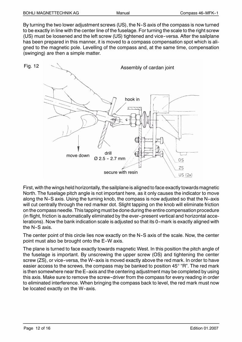
By turning the two lower adjustment screws (US), the N--S axis of the compass is now turnedto be exactly in line with the center line of the fuselage. For turning the scale to the right screw(US) must be loosened and the left screw (US) tightened and vice--versa. After the sailplanehas been prepared in this manner, it is moved to a compass compensation spot which is ali-gned to the magnetic pole. Levelling of the compass and, at the same time, compensation(swinging) are then a simple matter.
Fig. 12 Assembly of cardan joint
hook in
move downdrill
secure with resin
Ø 2.5 -- 2.7 mm
First, with thewings held horizontally, the sailplane is aligned to face exactly towardsmagneticNorth. The fuselage pitch angle is not important here, as it only causes the indicator to movealong the N--S axis. Using the turning knob, the compass is now adjusted so that the N--axiswill cut centrally through the red marker dot. Slight tapping on the knob will eliminate frictionon the compassneedle. This tappingmust be doneduring the entire compensationprocedure(in flight, friction is automatically eliminated by the ever--present vertical and horizontal acce-lerations). Now the bank indication scale is adjusted so that its 0--mark is exactly aligned withthe N--S axis.
The center point of this circle lies now exactly on the N--S axis of the scale. Now, the centerpoint must also be brought onto the E--W axis.
The plane is turned to face exactly towards magnetic West. In this position the pitch angle ofthe fuselage is important. By unscrewing the upper screw (OS) and tightening the centerscrew (ZS), or vice--versa, the W--axis is moved exactly above the red mark. In order to haveeasier access to the screws, the compass may be banked to position 45° “R”. The red markis then somewhere near the E--axis and the centering adjustmentmay be completed by usingthis axis. Make sure to remove the screw--driver from the compass for every reading in orderto eliminated interference. When bringing the compass back to level, the red mark must nowbe located exactly on the W--axis.
Manual Compass 46--MFK--1BOHLI MAGNETTECHNIK AG
Edition 01.2007 Page 13 of 16
By this comparatively simple levelling procedure (which must be done accurately, however)the compass has been adjusted for zero bank and for a pitch angle of the fuselage correspon-ding to a flying speed of 100 to 110 km/h (62 to 70 mph). By the same procedure all stray ma-gnetic fields within the glider have been compensated. A check may be done by taking othercompass readings on different headings, e.g. from 30° to 30°. In most cases there will be nonoticeable deviation. A special deviation or correction table is consequently superfluous. Inan exceptional case only, when strong and uneven magnetic fields are influencing the com-pass, such a table may become necessary.
Due to the compensated stray magnetic fields the compass is not necessarily aligned withthe vertical or cross axis of the plane. The mirror must now be adjusted, so that the N--S axisof the scale appears vertical on the image, and the E--W axis horizontal. Thus, when circling,the image of the E--W axis may always be set parallel to the horizon. The bank angle scaleshall be visible along the top edge of the mirror, but it need not regularly be observed in flight.If the compensation area is aligned with the geographic (true) North, the local variation mustbe added or subtracted (if the red mark would be adjusted to the true North, the error whenfacing South would be twice the local variation).
If no calibration area is available, the compass may be levelled and compensated by liftingthe tail to the proper height and, with the wings held level, rotating the whole plane around360° several times in a row. By adjusting the upper center screw (ZS) and turning the knob,the compass is adjusted until the red mark describes a circle around the center point of thedial (and concentrical to the circles marked thereon). Obviously, this must be done way outon a field, away from constructions, steel, cars, etc. The compass can then be checked inflight by flying parallel to known tracks, such as roads, railway lines, etc. The local variationandpossible deviationsmust accurately be accounted forwhenusing this lastmethodof com-pensation.
Maintenance and care
The compass requires little maintenance. The maximum permissible shock acceleration isapprox. 25 g. Caremust be taken to avoid hitting the instrument against hard objects or lettingit drop. A dusty or dirty mirror shall be cleaned by breathing against and using cotton--wool.The same applies for the two dials. Make sure never to come close to the compass with astrongmagnet. When adjusting the screws with the screw--driver, turn gently and avoid swin-ging the needle against the stop with a jerk. If treatedwith care, the compasswill function pro-perly for years.
Technical data
Operating area: Northern hemisphere in areas with approx. 75° -- 45°inclination; this corresponds to latitudes betweenapprox. 65° -- 30° North.
Inclination on scale: inner circle = 72,5°, center circle = 65°, outer circle = 57,5°
Scale division: 10°
Temperature range: Minus 20°C to plus 60°C
Max. permissible acceleration: 25 g
Hysteresis: on ground ¦ 3°, in flight practically nil
Manual Compass 46--MFK--1BOHLI MAGNETTECHNIK AG
Edition 01.2007Page 14 of 16
General hints
Experience has shown that after final adjustment the adjusting screws “US” and “OS” and thecenter screw “ZS” must be secured with lacquer or resin. This is to prevent them from beco-ming loose during trailer transports (which would require a new adjustment).
If there is any chance that the bank indication scalemaybe de--regulated (by inattentionwhencleaning the canopy or if access to the compass is possible to spectators) this scale shouldalso be secured. This is donebyglueing oneof theedgesagainst the aluminium support.Onlyresin may be used, since dissolvents such as acetone, nitro, petrol or benzine etc. will causesmall cracks in perspex. The same applies to the spherical cap with the dial which must nevercome into contact with such a dissolvant.
If the water--level, which is supplied with the compass, shall remain installed, it is recommen-ded to secure it with lacquer.
Before take--off, the compass, like other instruments, should be protected from direct sunlightin order to avoid excessive heating.
Information on the use of compass 46--MFK--1model “South” for southern hemisphere
Generally, the mode “South” is suitable for use in Australia, New Zealand and South Africa.
Externally, the models “North” and “South” differ only by the design of the compass rose. Onmodel “South” the “S” appears in the mirror on top, “W” on the right, and “E” on the left. Withmodel “North” it is vice--versa: “N” in the mirror on top, “W” to the left and “E” to the right.
Installation is done exactly the same as for model “North”.
If a compass “North” is to be replaced by amodel “South”, the center screw “ZS” must be un-screwed, whereupon the compass can be taken off and the other one inserted. Attention:Don’t lose the concave washer!
Levelling of the model “South” is possible only in the Southern hemisphere. It is done in thesame manner as for model “North”. A compensating spot with magnetic North indication isuseful; otherwise theN--S and E--Waxesmay be established by other means (using an other,calibrated compass and marking the main directions with stretched strings.

Manual Compass 46--MFK--1BOHLI MAGNETTECHNIK AG
Edition 01.2007 Page 15 of 16

Manual Compass 46--MFK--1BOHLI MAGNETTECHNIK AG
Edition 01.2007Page 16 of 16
BOHLI manufacturing programme:
Standard program:
Magnetic holding devices
Dial test indicator holder
Selecting magnet
Demagnetizer for steel
Holding and sticking magnets
Rubber magnets
Sailplane instruments
Ask for our price list
BOHLI MAGNETTECHNIK AGDammstrasse 15
CH -- 4500 Solothurn / Switzerland
Phone +41 32 622 04 33Telefax +41 32 622 14 82
[email protected]://www.bohli--magnete.ch

SSTTAANNDDAARRDD PPRREECCIISSIIOONN AALLTTIIMMEETTEERR WWIINNTTEERR 44 FFGGHH 1100
Application
2-pointer altimeter for measuring absolute und relative altitudes in the 0-10 000 m or 0-20 000 ft range. Indicating range: item No. 4110: 0-1000-10 000 m item No. 4320: 0-1000-20 000 ft Gradations: item No. 4110: large pointer 10 m, small pointer 100 m, 3rd pointer 5000 ft item No. 4320: large pointer 20 ft, small pointer 200 ft, 3rd pointer 5000 ft
Technical data
Airtight, black plastic housing. Connection via hose from static pressure sensor to hose connector on rear. Kollsman window with millibar scale, reading from 940 to 1050 millibars. See scale drawing for installation dimensions. Weight 0,330 kg. Linear scale The 4 FGH 10 altimeter can be fitted withp a scale ring.
Scale Ring
Prior to a cross-country flight, the altimeter is usually set to field elevation.
Atmospheric pressure reduced to pressure at sea level (QNH pressure) is then indicated in the Kollsman window. Throughout the flight, the altimeter reads height above sea level.
In many instances, it is also desirable to know one’s relative altitude above a defined landmark, as well as height above sea level. On a final approach, for example, it es essential to know one’s height above the landing field at any given time.
Once the arrow on the rotatable scale ring has been set to the elevation of the landing field, altitude above the field can be read off the gradations at any time until touchdown (redaing corresponds to the QFE setting).
Further applications include the safe crossing of ground obstacles (mountain ranges) or control zones, cases in which the difference in altitude can be read directly once the ring has been correctly adjusted.
The scale ring has also proved particularly useful for destination approach calculations in performance gliding.
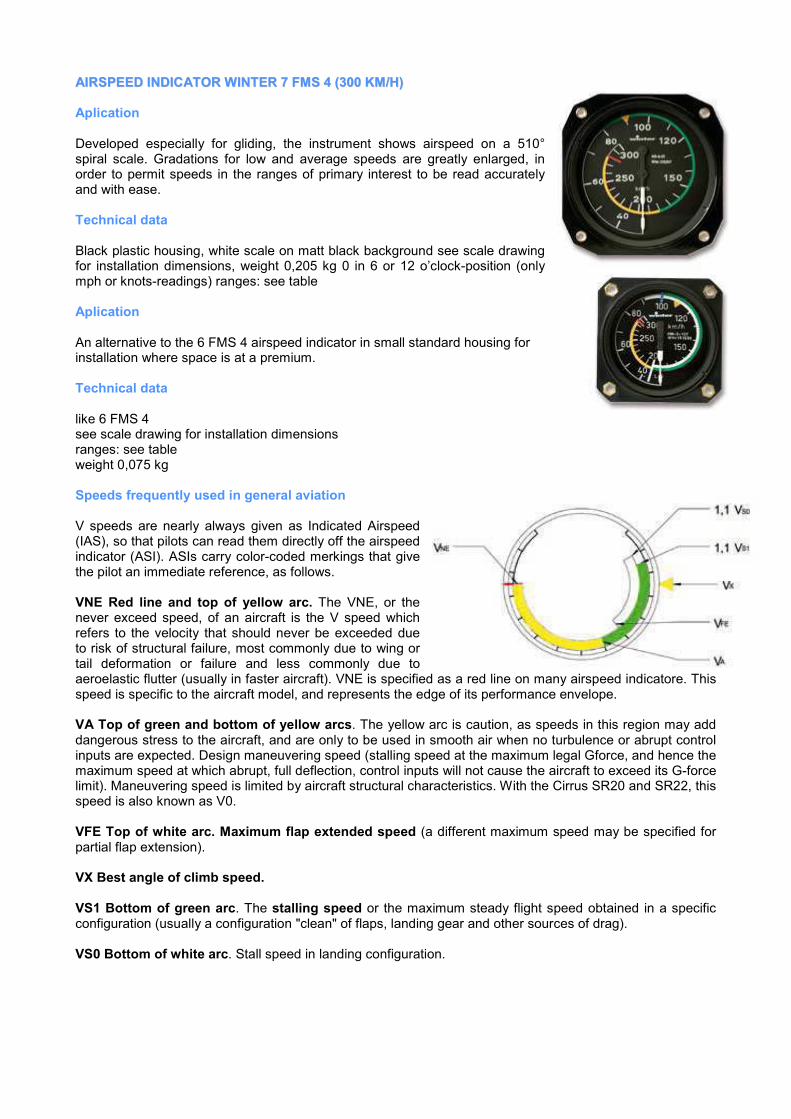
AAIIRRSSPPEEEEDD IINNDDIICCAATTOORR WWIINNTTEERR 77 FFMMSS 44 ((330000 KKMM//HH))
Aplication
Developed especially for gliding, the instrument shows airspeed on a 510° spiral scale. Gradations for low and average speeds are greatly enlarged, in order to permit speeds in the ranges of primary interest to be read accurately and with ease.
Technical data
Black plastic housing, white scale on matt black background see scale drawing for installation dimensions, weight 0,205 kg 0 in 6 or 12 o’clock-position (only mph or knots-readings) ranges: see table
Aplication
An alternative to the 6 FMS 4 airspeed indicator in small standard housing for installation where space is at a premium.
Technical data
like 6 FMS 4 see scale drawing for installation dimensions ranges: see table weight 0,075 kg
Speeds frequently used in general aviation
V speeds are nearly always given as Indicated Airspeed (IAS), so that pilots can read them directly off the airspeed indicator (ASI). ASIs carry color-coded merkings that give the pilot an immediate reference, as follows.
VNE Red line and top of yellow arc. The VNE, or the never exceed speed, of an aircraft is the V speed which refers to the velocity that should never be exceeded due to risk of structural failure, most commonly due to wing or tail deformation or failure and less commonly due to aeroelastic flutter (usually in faster aircraft). VNE is specified as a red line on many airspeed indicatore. This speed is specific to the aircraft model, and represents the edge of its performance envelope.
VA Top of green and bottom of yellow arcs. The yellow arc is caution, as speeds in this region may add dangerous stress to the aircraft, and are only to be used in smooth air when no turbulence or abrupt control inputs are expected. Design maneuvering speed (stalling speed at the maximum legal Gforce, and hence the maximum speed at which abrupt, full deflection, control inputs will not cause the aircraft to exceed its G-force limit). Maneuvering speed is limited by aircraft structural characteristics. With the Cirrus SR20 and SR22, this speed is also known as V0.
VFE Top of white arc. Maximum flap extended speed (a different maximum speed may be specified for partial flap extension).
VX Best angle of climb speed.
VS1 Bottom of green arc. The stalling speed or the maximum steady flight speed obtained in a specific configuration (usually a configuration "clean" of flaps, landing gear and other sources of drag).
VS0 Bottom of white arc. Stall speed in landing configuration.

Airspeed-indicator with Grosskinsky-variable-camberflap ring
Application
As is generally known, wing load and, in turn, the optimum flap positions for the various speed ranges of a variable-flap glider changes with take-off weight. Until now, selecting the right flap position has ivolved using special tables carried on board or observing a confusingly large number of marks on the airspeed indicator. The new adjustable ring for airspeed indicators makes these complicated methods things of the past.
Features
As the illustrations shows, the ring has a double scale for aircraft weight “G” and wing load “G/F”. Four arrows can also be seen, showing the corresponding angles for the flap positions. The number of arrows depends on the number of flap positions for the type of glider in question – are shown here. Like the MacCready ring of the variometer, the rotable ring is simply push-fitted over the airspeed indicator.
Use
Once the take-off weight has been calculated by adding the dead weight of the aircraft, the weight of the pilot and the weight of any water ballast on board, the “G” scale is simply turned until this figure is aligned with the 0 mark of the airspeed indicator. The arrows on the ring now automatically show the correct flap positions on the airspeed-indicator scale.
Furthermore, the correct wing load for the takeoff weight can be read from the “G/F”scale and entered in the electric variometer, it fitted. If wing load changes in the course of the flight, due to a reduction in ballast, for example, the ring need only be turned back to the new flying weight, and immediately, the arrows show the new, flight dependend flap positions.
The ring is calibrated for a standard preset acceleration of 1 g. If values as high as 1,3 g should occur, as they do in high-performance competition gliding, a second ring with the appropriate values can be fitted during the flight, or changed as required.
If the Großkinsky ring is not ordered along with a new airspeed indicator, please send us the airspeed indicator and state the type of aircraft in which it is installed, because the scales vary from model to model. Only the 6 FMS 4 or 7 FMS 4 series airspeed indicators with 510° scales are suitable.

VVAARRIIOOMMEETTEERR 55 SSTTVV 55
Vane type variometers measure the change in air pressure inherent to changes in altitude. The instrument consists of a cylindrical chamber with a precision-fit baffle plate (vane) rotating on shockproofjewel bearings and centered by a coil spring. The vane divides the chamber in two: one section is open to static pressure, while the other is connected to an expransion tank, in which a volume of air is insulated against the thermal effects.
Differences in pressure are compensated by the narrow gap between vane and chamber wall. There is a change in static pressure when an aircraft climbs or descends, and a differential pressure is established between the two sections of the chamber. The resultant deflection of the vane provides a measure of the vertical speed and this deflection is transferred to the pointer of the instrument.
The response rate of a variometer is important. In high-performance gliding, upcurrents can be identified all the quicker and used all the more efficiently if the variometer responds without delay.
Defined as the length of time the instrument takes to reach 65% of its final reading in response to a sudden change in vertical speed, the time constant serves as a standard for gauging speed of response. The faster a variometer responds, the smaller is its time constant.
Vane type variometers with large measuring ranges such as 5 StV 5 (±10 m/sec. and ±15 m/sec.) have small time constants. The volume of the expansion tank must be increased in order to achieve comparable figures with variometers having the most common measuring range (±5 metres/second).
Application
Indicates the aircrafts’s vertical speed (rate od climb, rate of descent). The variometer is the most valuable aid on all types of aircraft for pilots wishing fully to expoit the prevailing thermal concitions. The variometer with linear dial calibration can be used in conjunction with a MacCready ring. The separate 0,45 litre equalization reservoir is easy to install. responsive and exact display, linear dial calibration, shock-resistant shafts
Technical data
Black plastic housing see scale drawing indicating range see table for installation dimensions, see table of vane type variometers for time constants, weight 0,260 kg volume of expansion tank 0,45 litre equalization reservoir dimensions : 0,45 litre, 65 mm Ø, 280 mm long, 190 g 0,9 litre, 80 mm Ø, 350 mm long, 300 g
Maintenance
A leak test should be performed annually. Otherwise the instruments require no maintenance.
Test and repair
Normally the instruments remain serviceable and accurate over a long period of time. If test or repair become necessary, the instrument is to be sent to the manufacturer or a qualified repair station.
The instrument should be packed in shock absorbing material, and the connection fittings should be sealed.
We strongly advise against service by unqualified personnel. We recommend that variometers are retested after 5 years.
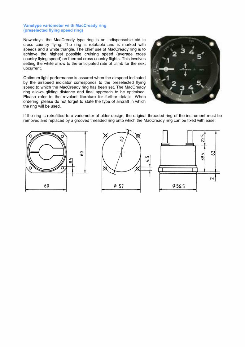
Vanetype variometer wi th MacCready ring (preselected flying speed ring)
Nowadays, the MacCready type ring is an indispensable aid in cross country flying. The ring is rotatable and is marked with speeds and a white triangle. The chief use of MacCready ring is to achieve the highest possible cruising speed (average cross country flying speed) on thermal cross country flights. This involves setting the white arrow to the anticipated rate of climb for the next upcurrent.
Optimum light performance is assured when the airspeed indicated by the airspeed indicator corresponds to the preselected flying speed to which the MacCready ring has been set. The MacCready ring allows gliding distance and final approach to be optimised. Please refer to the revelant literature for further details. When ordering, please do not forget to state the type of aircraft in which the ring will be used.
If the ring is retrofitted to a variometer of older design, the original threaded ring of the instrument must be removed and replaced by a grooved threaded ring onto which the MacCready ring can be fixed with ease.


Table of contents
Section 1 GENERAL INFORMATION Page
1.1 Introduction 1-1
1.2 Purpose of equipment 1-1
1.3 General description 1-2
1.4 Variants survey 1-3
1.5 Specifications 1-5
1.5.1 General data Transceiver 1-5
1.5.2 Receiver specifications 1-5
1.5.3 Transmitter specifications 1-6
1.5.4 Optional functions 1-7
1.6 Certification 1-7
1.7 Accessories 1-7
1.8 Scope of delivery 1-8
1.9 Software 1-8
AR 3201 - ( )
DV 28110.03/.04 Issue 04/92 1-I

Blank
AR 3201 - ( )
1-II DV 28110.03/.04 Issue 04/92

Section 1 GENERAL INFORMATION
1.1 Introduction
The following Handbooks describe the VHF-communications transceiver AR 3201 - ( ).
The Handbooks DV 28110.03 (,, Installation and Operation ‘‘) and DV 28110.04 (,,Maintenance and
Repair‘‘) contain the following sections :
Section DV 28110.03 DV 28110.04
1 General Information X X
2 Installation X X
3 Operation X X
4 Theory of Operation X
5 Maintenance and Repair X
6 Illustrated Parts List X
7 Modification and Changes X
8 Circuit Diagrams X X
1.2 Purpose of equipment
The VHF transceiver permits transceiver communication on 760 channels in the frequency range
118.000 MHz to 136.975 MHz with a channel spacing of 25 kHz. It can also be limited to 135.975 MHz
= 720 channels by incorporating a different PROM. Extensions for additional modes such as
temperature and operating voltage measurements, etc. are provided for.
The VHF transceiver is physically designed for unrestricted application in category II aircraft. In the
environmental categories there is no limitation for application in the instrument panel and for use in
AR 3201 - ( )
DV 28110.03/.04 Issue 04/92 Page 1-1

rigid fuselage mounting in all aircraft. The VHF transceiver is designed for compliance with RTCA and
EUROCAE airworthiness requirements.
1.3 General description
The VHF transceiver is designed as a single-block unit with dimensions in keeping with 58 mm diameter
standard instrument size. Mounting is by means of four screws (behind-panel fitting). AII controls and
indicators are located on the front panel. The rear panel locates the connector for connecting the
transceiver to aircraft wiring, the antenna socket and a test connector.
The transceiver features a single superhet receiver. A squelch circuit suppresses noise and input
signals below a specific field strength. The switching threshold is adjustable from without through the
case. The squelch can be defeated with the squelch switch.
The transmitter has wideband tuning over the range 118.000 MHz to 136.975 MHz. Transmitter output
power is greater than 5 watt. In transmitter operation sidetone is automatically on. In transceiver with
serial No. of 4000 and above, an arrow flashes on and off in the upper left side of the LCD during
transmission
The injection frequency of the receiver and the transmit frequency of the transmitter are generated by
a voltage-controlled oscillator (VCO) which is signalled by a digital frequencysynthesizer in conjunction
with a microprocessor.
The microphone input is designed for a dynamic microphone or for a standard microphone, the
transceiver being infactory-set for a dynamic microphone. Conversion to a standard microphone is
done in transceivers up to serial No. 86 by resoldering a jumper on the soldering side of the audio
module. As of serial number No. 86 the conversion is made by reconnecting a wire jumper on the
component side of the audio module. The microphone input is connected to a dynamic compressor
which maintains the modulation depth constant over a microphone input voltage range of approx.
40 dB.
The frequency indication is a liquid crystal display ( LCD). The MHz and kHz frequency selectors permit
selection of the desired channel frequency. The MHz frequency selector indexes in steps of 1 MHz,
the kHz frequency selector in 25 kHz steps.
The transceiver also contains a memory for storing four different channel frequencies, even when the
transceiver is OFF. The stored frequencies are called up by the channel selector switch in positions
1 - 4. In switch position A a further channel frequency can be set which is, however, lost when the
transceiver is switched off. In transceiver with serial No. fo 4000 or above, the channel frequency set
in position A is also stored and not deleted when the unit is powerd down.
In addition, when the VHF transceiver is powered up, a self-test function is automatically activated to
test the LCD. For a period of a few secounds, all of the segments in the LCD flash on (188.88).
Aterwards, either the frequency 121.5 MHz appears (channel selector switch in position A), or one of
the 4 stored frequencies (depending on the position of the channel selector switch). The VHF
transceiver is now ready for operation.
In Transceiver with serial No. of 4000 or above, either the most recently set frequency in channel A
appears, or one of four stored frequencies (depending on the position of the channel celector switch).
When the self-test function is activated, an arrow flashes on and off in addition to the digits 188.88
(⇐ 188.88).
AR 3201 - ( )
Page 1-2 DV 28110.03/.04 Issue 04/92

The transceiver also contains a stage for monitoring the aircraft supply voltage. This stage is ON as
soon as the transceiver is switched on. Should the aircraft supply voltage drop to 11 V - 10.5 V, the
readout will commence flashing.
For operation on an 28 V aircraft system a voltage regulator (VR 2011 ) is necessary. In aircraft with
no power circuit (gliders) the battery box (BK 5) is provided.
When using the emergency power unit EPU 400 the transceiver can be continued to be operated at
reduced output power (12 V operating voltage) even when aircraft power is down.
When operating the IC mode, the transceiver can be used for intercommunications.
The auxiliary audio input permits input of audio signals from other equipment in the aircraft, however,
these auxiliary audio input is standard as of module No. 471 . Up to module No. 470 this feature was
only available as an option.
If LCD illumination is required, it can be connected either directly to the operating voltage or to a
dimmer.
The standard version can be extened by optional voltage and temperature measuring facilities without
affecting the airworthiness of the transceiver.
An optional voltage and temperature measurement circuit permits measurement of either two different
voltages or two different temperatures or a single voltage and a single temperature with the aid of two
corresponding sensors and two external pushbuttons. The LCD provides indication on pressing the
external pushbuttons for approx. 4 seconds. Temperature can be indicated in Fahrenheit or Celsius.
1.4 Variants survey
Table 1 -1 surveys the variants of transceiver AR 3201 - ( ). The various variants are not different in
appearance, i.e. dimensions, case depth, etc. being the same for all variants. The necessary
accessories are given in the List of Accessories at the end of Section 1 for the various variants, all of
which have no effect on airworthiness of the transceiver.
AR 3201 - ( )
DV 28110.03/.04 Issue 04/92 Page 1-3

Transceiver AR 3201-( )
Drawing No./
Order No
Type Voltage
measurement
Tamperature
measurement
in deg Celsius
Temperature
measurement
in deg.
Fahrenheit
760
channel
720
channel
28110-00000.000
389.528-910
AR 3201-( ) no no no yes
28111 -00000.000
397.156-910
AR 3201-(1) yes yes no yes
28112-00000.000
397.164-910
AR 3201-(2) yes no yes yes
28113-00000.000
397.172-910
AR 3201-(3) no yes
two different
temperatures
no yes
28114-00000.000
397.180-910
AR 3201-(4) no no yes
two different
temperatures
yes
28120-00000.000
767.018-910
AR 3201-(10) no no no yes
28121 -00000.000
767.026-910
AR 3201-(11) yes yes no yes
28122-00000.000
767.034-910
AR 3201-(12) yes no yes yes
28123-00000.000
767.042-910
AR 3201-(13) no yes
two different
temperatures
no yes
28124-00000.000
767.050-910
AR 3201-(14) no no yes
two different
temperatures
yes
Table 1-1
AR 3201 - ( )
Page 1-4 DV 28110.03/.04 Issue 04/92

1.5 Specifications
1.5.1 General data Transceiver
Operating voltage 12,4 V . . . 15,1 V
Emergency operation (10,0 V) Intelligible communication
Current consumption 14 V without
Panel illumination
Receive ,, stand by ‘‘ typ. 70 mA
Receive ,, stand by ‘‘ with auxiliary input typ. 90 mA
Transmit typ. 1 .8 A
Panel illumination 13,8 V / 40 mA DC
Fuse 5A
Operating temperature range D1 - 20° . . .+ 55°C,
Env. Cat. RTCA DO - 160A shorttime temperature + 70°C
Altitude max. D1 50000 ft
Env. Cat. RTCA DO - 160A
Vibration MNO
Env. Cat. RTCA DO - 160A
Dimensions
Panel 60.6 mm x 60.6 mm
Mounting depth 212.5 mm
Weight 0.9 kg
1.5.2 Receiver specifications
Type Receiver Single superhet
Frequency range 118.000 MHz . . . 136.975 MHz
Channels 760
Channel spacing 25 kHz
Sensitivity (mod. 1000 Hz/30%) ≤ 5µV emf for 6 dB S+N
N
Bandwidth ≥ ± 8 kHz at 6 dB down
Selectivity ≥40 dB at ± 17 kHz
≥60 dB at ± 25 kHz
AR 3201 - ( )
DV 28110.03/.04 Issue 04/92 Page 1-5
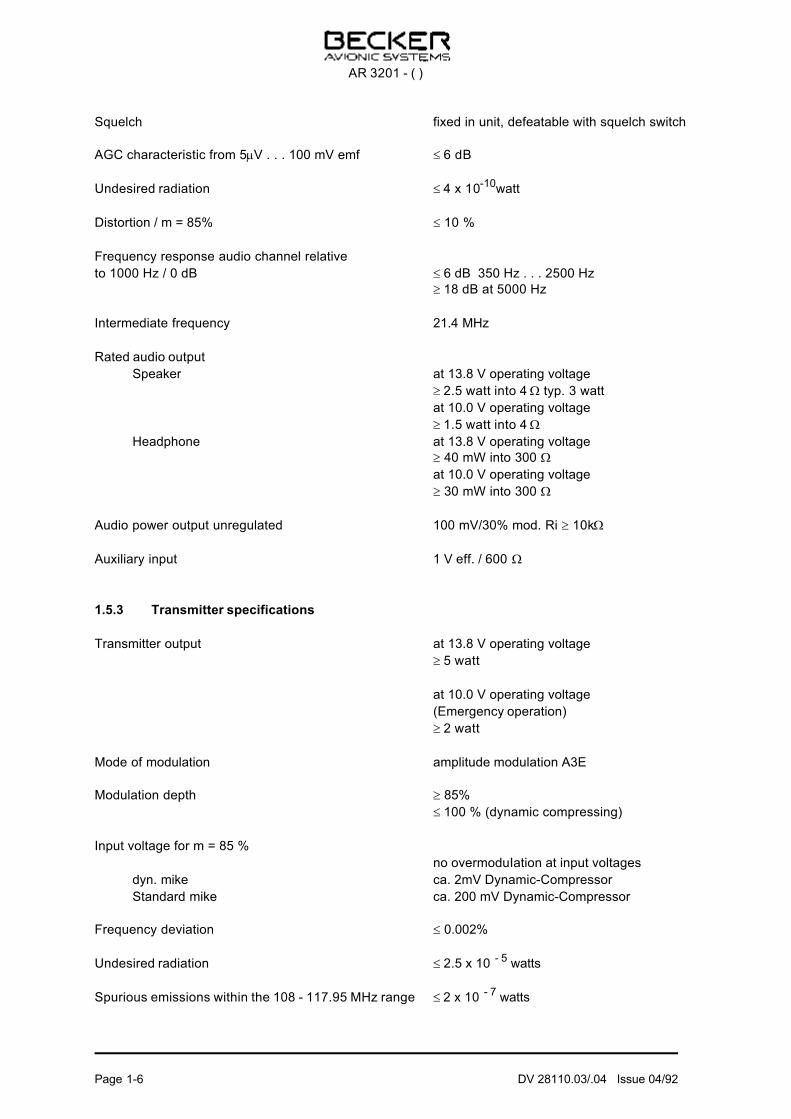
Squelch fixed in unit, defeatable with squelch switch
AGC characteristic from 5µV . . . 100 mV emf ≤ 6 dB
Undesired radiation ≤ 4 x 10⁻¹⁰watt
Distortion / m = 85% ≤ 10 %
Frequency response audio channel relative
to 1000 Hz / 0 dB ≤ 6 dB 350 Hz . . . 2500 Hz
≥ 18 dB at 5000 Hz
Intermediate frequency 21.4 MHz
Rated audio output
Speaker at 13.8 V operating voltage
≥ 2.5 watt into 4 Ω typ. 3 watt
at 10.0 V operating voltage
≥ 1.5 watt into 4 Ω
Headphone at 13.8 V operating voltage
≥ 40 mW into 300 Ω
at 10.0 V operating voltage
≥ 30 mW into 300 Ω
Audio power output unregulated 100 mV/30% mod. Ri ≥ 10kΩ
Auxiliary input 1 V eff. / 600 Ω
1.5.3 Transmitter specifications
Transmitter output at 13.8 V operating voltage
≥ 5 watt
at 10.0 V operating voltage
(Emergency operation)
≥ 2 watt
Mode of modulation amplitude modulation A3E
Modulation depth ≥ 85%
≤ 100 % (dynamic compressing)
Input voltage for m = 85 %
no overmoduIation at input voltages
dyn. mike ca. 2mV Dynamic-Compressor
Standard mike ca. 200 mV Dynamic-Compressor
Frequency deviation ≤ 0.002%
Undesired radiation ≤ 2.5 x 10 - 5 watts
Spurious emissions within the 108 - 117.95 MHz range ≤ 2 x 10 - 7 watts
AR 3201 - ( )
Page 1-6 DV 28110.03/.04 Issue 04/92
Frequency response ≤ 6 dB 350 Hz . . . 2500 Hz
Distortion / m = 85% / 1000 Hz ≤ 10%
m = 85% / 350 - 1000 Hz ≤ 20%
Carrier noise level ≥ 35 dB
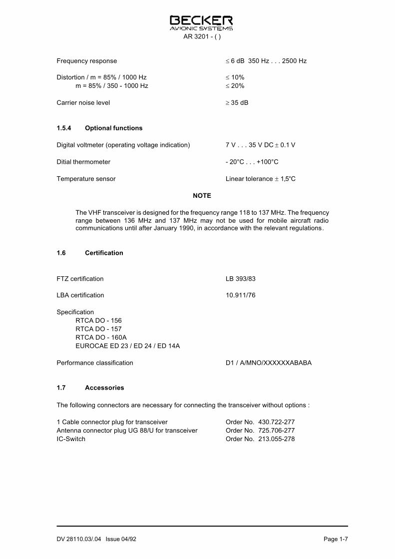
1.5.4 Optional functions
Digital voltmeter (operating voltage indication) 7 V . . . 35 V DC ± 0.1 V
Ditial thermometer - 20°C . . . +100°C
Temperature sensor Linear tolerance ± 1,5°C
NOTE
The VHF transceiver is designed for the frequency range 118 to 137 MHz. The frequency
range between 136 MHz and 137 MHz may not be used for mobile aircraft radiocommunications until after January 1990, in accordance with the relevant regulations.
1.6 Certification
FTZ certification LB 393/83
LBA certification 10.911/76
Specification
RTCA DO - 156
RTCA DO - 157
RTCA DO - 160A
EUROCAE ED 23 / ED 24 / ED 14A
Performance classification D1 / A/MNO/XXXXXXABABA
1.7 Accessories
The following connectors are necessary for connecting the transceiver without options :
1 Cable connector plug for transceiver Order No. 430.722-277
Antenna connector plug UG 88/U for transceiver Order No. 725.706-277
IC-Switch Order No. 213.055-278
AR 3201 - ( )
DV 28110.03/.04 Issue 04/92 Page 1-7

When the transceiver incorporates the temperature or voltage measurement option, the following items
are required :
1 Cable connector complete Order No. 431.036-950
Detail parts
1 Cable connector plug for option Order No. 710.687-277
Temperature sensor - 65°C . . . 150°C Order No. 431.044-955
Bounceless pushbuttons Order No. 724.742-278
1.8 Scope of delivery
Screw block Order No. 472.875-203
Spring washer Order No. 213.126-213
1.9 Software
Frequency synthesizer, frequency storage and frequency display of the AR 3201 - ( ) are controlled
by a microprocessor. The software used has been categorized to Function Criticality Category
,,ESSENTIAL‘‘
accordirig to the guide,lines of RTCA DO - 178.
Uses elass was determined to be
,,CLASS X‘‘
AR 3201 - ( )
Page 1-8 DV 28110.03/.04 Issue 04/92
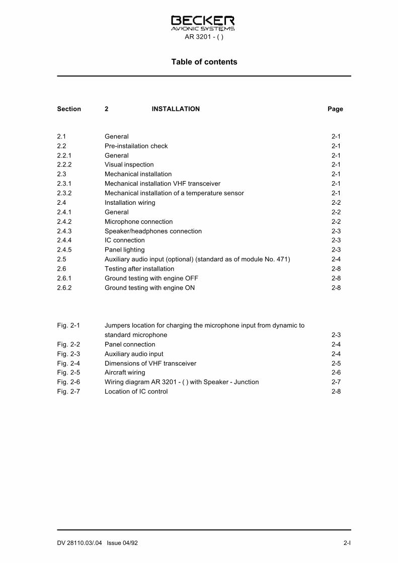
Table of contents
Section 2 INSTALLATION Page
2.1 General 2-1
2.2 Pre-instailation check 2-1
2.2.1 General 2-1
2.2.2 Visual inspection 2-1
2.3 Mechanical installation 2-1
2.3.1 Mechanical installation VHF transceiver 2-1
2.3.2 Mechanical installation of a temperature sensor 2-1
2.4 Installation wiring 2-2
2.4.1 General 2-2
2.4.2 Microphone connection 2-2
2.4.3 Speaker/headphones connection 2-3
2.4.4 IC connection 2-3
2.4.5 Panel lighting 2-3
2.5 Auxiliary audio input (optional) (standard as of module No. 471) 2-4
2.6 Testing after installation 2-8
2.6.1 Ground testing with engine OFF 2-8
2.6.2 Ground testing with engine ON 2-8
Fig. 2-1 Jumpers location for charging the microphone input from dynamic to
standard microphone 2-3
Fig. 2-2 Panel connection 2-4
Fig. 2-3 Auxiliary audio input 2-4
Fig. 2-4 Dimensions of VHF transceiver 2-5
Fig. 2-5 Aircraft wiring 2-6
Fig. 2-6 Wiring diagram AR 3201 - ( ) with Speaker - Junction 2-7
Fig. 2-7 Location of IC control 2-8
AR 3201 - ( )
DV 28110.03/.04 Issue 04/92 2-I

Blank
AR 3201 - ( )
2-II DV 28110.03/.04 Issue 04/92

Section 2 INSTALLATION
2.1 General
Installation of the VHF communication transceiver and the battery box depends on the type of aircraft
and equipment involved, the instructions given in this section thus being only generally applicable.
2.2 Pre-instailation check
2.2.1 General
Prior to fitting the new system in the aircraft, the units must be checked according to the following
procedure to establish whether they have been damaged in transit.
2.2.2 Visual inspection
Prior to commissioning the equipment, carry out a visual inspection to establish any of the following
deficiencies.
1. Soilage, dents, scratches, corrosion, broken fasteners, damaged paintwork on enclosures and
parts thereof.
2. Soilage and scratches on the nameplate, front panel and markings.
3. Soilage, bends or broken-off pins, cracked plug and socket inserts.
4. Soilage and mechanical damage to rotary switches, LCD elements, knobs and pushbutton.
2.3 Mechanical installation
2.3.1 Mechanical installation VHF transceiver
The VHF transceiver is designed for incorporating in an aircraft instrument panel in behind panel
installation. The circular cutout and the fastener holes must be drilled in accordance with the standard
for small size instruments. Location must be min. 30 cm away from the magnetic compass of the
aircraft to avoid the compass being affected by the transceiver. Dimensional requirements are shown
in Fig. 2-4. Four DUZ fasteners (supply) are used to secure the unit.
2.3.2 Mechanical installation of a temperature sensor
The VHF transceiver permits indication of temperatures in the range - 20° C to +100° C with the aid
of an integral measuring circuit and a connected remote temperature sensor. The latter is located in
accordance with the particular requirements and local conditions. The wiring can be seen from Fig. 2-5.
Only use shielded flexed leads, noting the color coding of the connecting cables. The red lead must
be connected to J 3101/8, the blue lead to J 3101/2. The shielding must be connected to pin 4 of
J 3101.
AR 3201 - ( )
DV 28110.03/.04 Issue 04/92 Page 2-1

The temperature measuring circuit in the VHF transceiver and the temperature sensor are calibrated
in the factory together for optimum temperature measuring accuracy. Should the device or the
temperature sensor develop a fault or should the transceiver need replacing, the device will need
recalibrating according to the instructions as given in Section 5, Item 5.7.
2.4 Installation wiring
2.4.1 General
Fig. 2-5 illustrates the installation wiring of the VHF transceiver. In wiring the VHF transceiver the
battery voltage feeder cable should be AWG 20.
NOTE
a) Only use airworthy cable, i.e. self-extinquishing in suitable AWG for power supply and the other
lines.
b) Pull rubber sleeves over the solder juctions on the instrument connector.
c) A 3 A fuse or circuit breaker must be incorporated in the power supply.
d) Prior to switching on the unit, carefully check the wiring, particularly making sure that +ve and -ve
are not confused.
CAUTION
The AR 3201 - ( ) is only protected against wrong polarity when a fuse is incorporated
in the power supply, i.e. so that the fuse blows, leaving the unit undamaged. If no fuse isprovided, the unit can be ruined. In this case, the unit is not covered by our guarantee.
Suitable type cable sets are available for aircraft wiring (contact manufacturer).
CAUTION
Never tie any aircraft wiring into the connecting lines. In addition, the connecting cablemust not be put down together with line carrying pulsed information (IFC’s, DME, XPR,
SLAVED GYRO) the same applying to autopilot supply and control lines.
2.4.2 Microphone connection
The VHF-transceiver features a microphone amplifier as standard which is compatible with both a
dynamic microphone and a standard microphone. Unless stated otherwise, the transceiver is set in
the factory for a dynamic microphone connection. By resoldering jumper Br 4001 on the audio module
the microphone input can be changed from a dynamic microphone to a standard microphone. This
jumper is accessible after unscrewing the case and removing the audio module. As of serial No. 86,
conversion from dynamic to standard microphone has been simplified, jumper 4401 then no longer
requiring resoldering but merely reconnecting, without requiring removal of the audio module.
AR 3201 - ( )
Page 2-2 DV 28110.03/.04 Issue 04/92
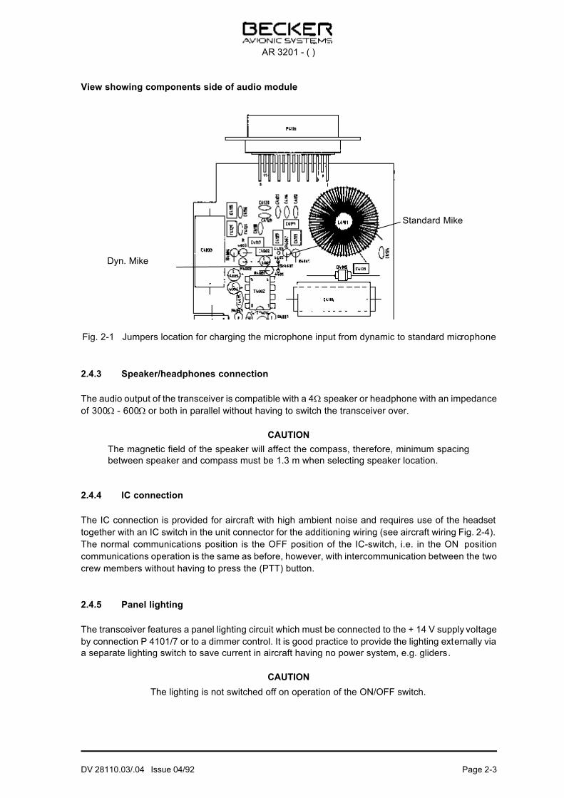
View showing components side of audio module
Fig. 2-1 Jumpers location for charging the microphone input from dynamic to standard microphone
2.4.3 Speaker/headphones connection
The audio output of the transceiver is compatible with a 4Ω speaker or headphone with an impedance
of 300Ω - 600Ω or both in parallel without having to switch the transceiver over.
CAUTION
The magnetic field of the speaker will affect the compass, therefore, minimum spacing
between speaker and compass must be 1.3 m when selecting speaker location.
2.4.4 IC connection
The IC connection is provided for aircraft with high ambient noise and requires use of the headset
together with an IC switch in the unit connector for the additioning wiring (see aircraft wiring Fig. 2-4).
The normal communications position is the OFF position of the IC-switch, i.e. in the ON position
communications operation is the same as before, however, with intercommunication between the two
crew members without having to press the (PTT) button.
2.4.5 Panel lighting
The transceiver features a panel lighting circuit which must be connected to the + 14 V supply voltage
by connection P 4101/7 or to a dimmer control. It is good practice to provide the lighting externally via
a separate lighting switch to save current in aircraft having no power system, e.g. gliders.
CAUTION
The lighting is not switched off on operation of the ON/OFF switch.
Dyn. Mike
Standard Mike
AR 3201 - ( )
DV 28110.03/.04 Issue 04/92 Page 2-3

Fig. 2-2 Panel connection
2.5 Auxiliary audio input (optional) (standard as of module No. 471)
The auxiliary audio input permits audio input from other equipment in the aircraft. This input can only
be heard, however, in the RX mode. The possibility of circuiting two units together finds application in
aircraft having, for instance, only one transceiver and one NAV receiver. When using the auxiliary
audio input, a 680Ω resistor must be switched to GND. When circuiting units together, 100Ω decoupling
resistors must be included (see following diagrams). Output of the audio listening amplifier requires
an audio input voltage of approx. 1 V/600Ω .
Fig. 2-3 Auxiliary audio input
AR 3201 - ( )
Page 2-4 DV 28110.03/.04 Issue 04/92

Fig. 2-4 Dimensions of VHF transceiver
AR 3201 - ( )
DV 28110.03/.04 Issue 04/92 Page 2-5

Fig. 2-5 Aircraft wiring
AR 3201 - ( )
Page 2-6 DV 28110.03/.04 Issue 04/92
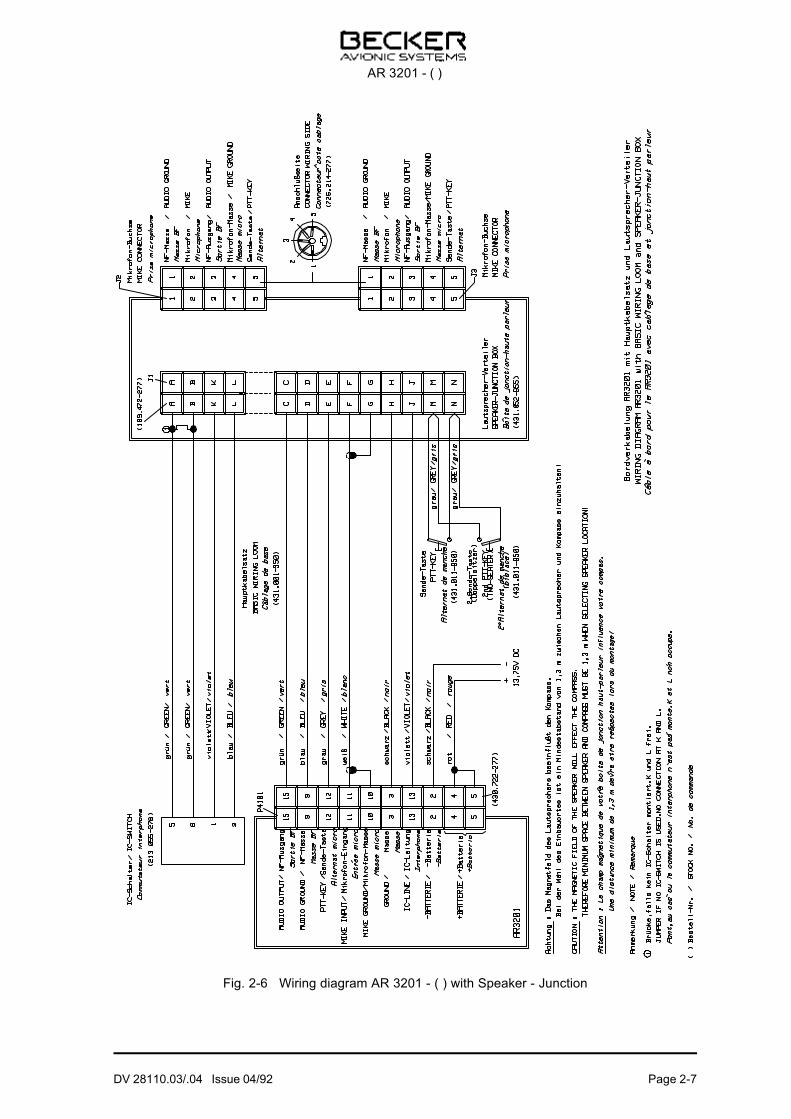
Fig. 2-6 Wiring diagram AR 3201 - ( ) with Speaker - Junction
AR 3201 - ( )
DV 28110.03/.04 Issue 04/92 Page 2-7

2.6 Testing after installation
2.6.1 Ground testing with engine OFF
After installing the transceiver, measure antenna matching between antenna base and antenna feeder
by means of a VHF reflection meter (voltage/standing-wave meter).
Over the complete frequency range of the transceiver, the voltage/standing-wave ratio must be within
the value 3 : 1. Exceeding this value is an indication of mismatch, which can be due to a wrong or
inadequate counterweight.
After antenna measurement, carry out a voice test with the ground station.
2.6.2 Ground testing with engine ON
With the engine running make sure that the aircraft voltage is within the permissible tolerances at
approx. 14 V. Make the test at engine cruising speed. Carry out speech test at a long distance away
from the ground station. At engine cruising speed the cabin noise of the aircraft must only be heard
muted thus making for clear, intelligible conversation. Hold microphone close to lips when speaking.
Switch on intercommunications by means of the IC switch (when provided) and carry out speech test
at engine cruising speed.
If necessary, correct volume by means of IC control (see Fig. 2-7).
Apply squelch switch and check squelch function. The squelch threshold can be set from without by
means of the squelch control.
CAUTION
In speaker operation no acoustic feedback should occur via the sidetone. If necessary, turn down
sidetone by means of the SIDETONE control.
Fig. 2-7 Location of IC control
AR 3201 - ( )
Page 2-8 DV 28110.03/.04 Issue 04/92
Table of contents
Section 3 Operating Instructions Page
3.1 Control and Indicators 3-1
3.2 Operating instructions for serial no. 0 to serial no. 3999 3-3
3.3 Operating instructions serial no. 4000 upwards 3-3
3.4 Storing frequencies 3-4
3.5 Setting the emergency frequency 3-4
3.5.1 Setting the emergency frequency on models with
serial numbers up to 3999 3-4
3.5.2 Setting the emergency frequency on models with
serial numbers of 4000 or above 3-4
3.6 LC display blinking 3-5
3.7 IC operation 3-5
3.8 Optional temperature, voltage measurement 3-5
3.9 Auxiliary audio input (optional) (standard as of module No. 471) 3-5
3.10 No channel freuency storage 3-5
3.11 Precautions 3-6
Fig. 3-1 Controls and indicators 3-1
AR 3201 - ( )
DV 28110.03/.04 Issue 04/92 3-I

Blank
AR 3201 - ( )
3-II DV 28110.03/.04 Issue 04/92

Section 3 Operating Instructions
3.1 Control and Indicators
Fig. 3-1 Controls and indicators
Controls and indicators Description Function
Volume control Potentiometer Turning control clock-wise
increases volume continuously.
ON/OFF switch combined with
squelch
3-position rocker switch Postion OFF :
VHF transceiver OFF.
Position ON :
VHF transceiver ON, squelch
OFF
(input noise audible).
Position SQL :
Transceiver ON, Squelch ON.
Input limited to transmitters
having a field strength
exceeding the set squelch
threshold
AR 3201 - ( )
DV 28110.03/04 Issue 02/92 Page 3-1

Controls and indicators Description Function
Channel selector 5-position rotary switch Position A :
When the transceiver is powerd
up, a brief test routine is
performed for the segments of
the display. Afterwards the
channel frequency 121,500 MHz
appears in the display and the
transceiver is ready for
operation. In models with serial
no. of 4000 or above, the moste
recently set frequency instead of
121,500 MHz.
The setting of channel
frequencies is performed with
the channel selector switch in
position A, regardless of the
units serial number
Position 1 through 4 :
If is wished to store a channel
frequency in any one of the four
memory locations, then channel
frequency to be stored must first
be set with the frequency
selector switch in position A.
Then the desired memory
location is selected using the
channel selector switch, and the
Store button is pressed.
Stored channel frequencies
remain in the memory even,
when the unit is powered down
and can be immediately called
up again after the unit has been
switch on.
MHz frequency selector switch Rotary switch (continuous) Switches the MHz steps
indicated by the frequency
readout.
kHz frequency selector switch Rotary switch (continuous) Switches the 25 kHz steps
indicated in the frequency
readout. The 3rd digit behind the
point is not indicated, e.g.
125.52 = 125.525 MHz.
Frequency indication LC display 5 digits When the unit switched on,
following completion of the self-
test routine the frequency
appers in the display on which
the unit is ready to operate.
During transmission, in models
with serial no. 4000 or above
arrow also flashes on and off.
AR 3201 - ( )
Page 3-2 DV 28110.03/04 Issue 02/92

Controls and indicators Description Function
Store button Pushbutton Briefly pressing the STORE
button causes the display
frequency to be stored in one of
the four memory locations,
provided that the channel
selector switch is not in position
A, but set to one of the four
memory positions (1 - 4). In
models with serial no. of 4000 or
above the STORE button must
be held depressed for approx. 2
seconds in order for the
displayed channel frequency to
be written into the selected
memory location.
3.2 Operating instructions for serial no. 0 to serial no. 3999
NOTE
Switch off transceiver when engines are started or stopped.
1. Switch on VHF transceiver with ON/OFF switch. For a few seconds the LC display reads 188.88
(display test). The transceiver then automatically switches to 121.500 MHz (emergency frequency)
when the channel selector is in position A. When it is positioned to one of the stored channel
frequencies (switch position 1-4) the display reads the stored channel frequency. To select a
channel frequency other than the stored channel frequencies, position channel selector to A and
then set the desired frequency by means of the MHz and kHz frequency selector switches.
2. Set to frequency of local ground station and position VOL control to center position.
3. Operate PTT key and call ground station. For optimum intelligibility keep microphone almost
touching lips.
4. On response from the ground station adjust for desired volume using VOL control.
5. Position ON/OFF switch to SQL to suppress weak input signals and input noise.
6. The sidetone volume can be adapted to the noise level of the aircraft by means of the sidetone
volume control.
3.3 Operating instructions serial no. 4000 upwards
NOTE
Switch off transceiver when engines are started or stopped.
1. Use the ON/OFF switch to turn on the VHF transceiver. For a few seconds, the digits 188.88 will
appear in the LCD (display test), as well as an arrow to indicate transmission mode. Afterwards
the VHF transmitter automatically switches to the most recently set frequency, if the channel
AR 3201 - ( )
DV 28110.03/04 Issue 02/92 Page 3-3

selector switch is in position A. If the channel selector switch is set to one of the stored channel
frequencies (any one of switch positions 1 through 4), then the channel frequency stored in that
memory location will appear in that display. If any other channel frequency is desired other than
those channel frequencies stored, then the channel selector switch should be set to position A
whereupon the desired frequency can be set using the MHz and kHz frequency selector dials.
2. Repeat steps 2 through 6 of Section 3.2.
3.4 Storing frequencies
Four memory locations are available for channel frequencies; each of these can be used to store any
channel frequency used for aircraft communications. They can be used in any desired order. To store,
proceed as follows :
a) Switch the channel selector switch to position A.
b) Use the MHz and kHz rotary switches to set the desired channel frequency.
c) Set the channel selector switch to the desired memory location.
d) Press the store button. For models with serial nos. of 4000 or above, the STORE button must be
held depressed for approx. 2 seconds.
NOTE
When overwriting a stored channel frequency, the same procedure as listed in steps a.
through d. should be followed.
3.5 Setting the emergency frequency
3.5.1 Setting the emergency frequency on models with serial numbers up to 3999
As already described in the operating instructions, the transceiver automatically switches to the
emergency frequency 121.500 MHz when the channel selector is positioned to A in switching the
transceiver on. To quickly switch to the emergency frequency in an emergency situation best procedure
is to switch the channel selector to A and to briefly switch the transceiver off/on, after which the
transceiver operates on the emergency frequency of 121.500 MHz. Under normal operating c onditions,
this can be set by means of the frequency selector switches. Another possibility is to store the
emergency frequency directly in one of the four available channels.
3.5.2 Setting the emergency frequency on models with serial numbers of 4000 or above
In models with serial numbers of 4000 or above, the emergency frequency 121.500 MHz does not
automatically appear when the channel selector switch is in position A and the transceiver is powered
up. It is recommended to store the distress frequency in one of the 4 memory locations.
In models with serial numbers of 4000 or above, an arrow flashes on and off in the LCD during
transmission. This is activated by the microprocessor, which outputs the instruction for this along with
the other data for the liquid-crystal display.
AR 3201 - ( )
Page 3-4 DV 28110.03/04 Issue 02/92
3.6 LC display blinking
As soon as the operating voltage for the transceiver drops to a value of 10.5 V to 11 V, the display
starts blinking to signalize, e.g. in battery operation that the batteries need recharging. The display will
start blinking in transmitter operation since this situation involves the highest current drain.
Since the discharge curves of batteries greatly depend on the type of batteries involved, e.g. lead-acid
or nickel batteries and on the ambient temperature of the batteries, no accurate indication can be given
as to how long the transceiver will remain fully functional on commencement of LC display blinking.
After a few keying cycles, the batteries can be empty in transmitter operation. In receiver operation
the instrument will remain functional for approx. 1-2 hours from commencement of blinking.
At an operating voltage of 10 V, the transceiver remains fully functional, but at reduced output power.
3.7 IC operation
1. Switch on IC switch.
2. Carry out speech test.
3. IC volume can be adapted to the noise Ievel of the aircraft by means of the IC volume control see
(Fig. 2-7).
3.8 Optional temperature, voltage measurement
When the standard version is supplemented by optional temperature and voltage measurement
circuits, note:
Temperature of voltage is measured continuously, whereas display follows only after pressing the
external pushbutton for approx. 4 sec, after which the previously set channel frequency appears.
NOTE
Independent of the temperature or voltage measurement, transceiver operation is
available at the set channel frequency even when the instrument is displaying a tempe-rature or voltage indication.
3.9 Auxiliary audio input (optional) (standard as of module No. 471)
Via the auxiliary audio input, other radio equipment (e.g.navigation receiver) can be monitored. When
the system is wired up for this application, the volume control of the remote equipment must be set so
that these inputs are intelligible and can be differentiated from each other.
During transmission the auxiliary input from the audio output amplifier is OFF.
3.10 No channel frequency storage
When the stored frequencies are lost when the transceiver is switched off, first measure the battery
voltage at the two button batteries which must be 2.4 V. These batteries are automatically charged
when the transceiver is switched on. When the unit is not switched on for a long time, or in lengthy
storage, the batteries may become discharged. To recharge the battery, it is sufficient to simply connect
the transceiver to the aircraft voltage for a couple of hours. The service life of a new battery is between
3 and 5 years.
AR 3201 - ( )
DV 28110.03/04 Issue 02/92 Page 3-5
3.11 Precautions
In order to secure a reliable transceiver operation, please note the following precautions:
a) Before running-up the engines, ensure that the transceiver is switched off.
b) Always conduct a verbal pre-flight check. Note that in the vicinity of a flight control, a broken or
shorted antenna cable must not necessarily impair the function. At a distance of 5-10 km from the
ground station, however, the connection will doubtlessly fail.
c) Transceiver communication contact should always be conducted using a clear, loud voice and by
speaking directly into the microphone. Otherwise, cabin background noise could predominate,
making the message inaudible.
d) Use suitable microphones or headset for aircraft only. With certain aircraft types (wood or fibre-glass
aircraft, gliders and helicopters) the signals transmitted by the unit’s antenna may be picked up
and enhanced by the integrated microphone amplifier (feed back). As a result, the signal received
by the flight control will be superimposed by whistles and/or strong distortion. This phenomenon
may not necessarily remain constant for all channels.
e) The PTT button of the microphone or control unit might jam, causing the system to remain in the
transmission mode. In order to rule such cases out, please ensure that the arrow in the frequency
display (from serial no. 4000 onwards) illuminates during the transmission mode, and extinguishes
when the PTT button is released.
AR 3201 - ( )
Page 3-6 DV 28110.03/04 Issue 02/92
Introduction
DX 50 FAI
DX 50
GPS-Flight information centre
User guide
LX navigation
+ 386 3 490 4670 + 386 3 490 46 71
[email protected] http://www.lxnavigation.si

Introduction
Introduction
DX-50 represents a GPS-Variometer system of the newest generation. The instrument is the combination of mo-
dern GPS technology and tradicional Variometer system.
This manual will lead you to know the device, its functions and all the advantages. Please read it cerfully through
before you build in the device. The best way to learn basic and more advanced facts about the DX-50 is to turn it on
at home and go step by step through this manual. We have made our best to achieve as little handling during the
flight as possible, if the on-ground preparation has been optimal.
Please beware that the airfield data (frequency, altitude, etc.) can very easily lose their topicality. These data, as also
the GPS-device itself, can only be helpful by the flight navigation. The appropriate on-groud preparation and the
use of appropriate data is therefore indispensable.
The manufacturer doesn’t take the responsibilty for possible mistakes or misprints in this text and gives no guaran-
ty for accuracy of this manual. Any possible technical alterations of the device itself or software are naturally exclu-
ded.
This manual has been written with all attention and we have made our best to avoid any mistakes but with all
respect please check any doubtful statement and let us know. We would be very grateful and for any comment we
thank you in advance.

Contents
I
CONTENTS
1 GENERAL DESCRIPTION...........................................................................................1
1.1 Technichal data ................................................................................................................................................. 1
1.2 Variometer system ............................................................................................................................................ 1
1.3 Electronic altitude meter .................................................................................................................................. 2
1.4 GPS-Navigation................................................................................................................................................. 2
1.5 Flight computer................................................................................................................................................. 3
1.6 Flight route drawer........................................................................................................................................... 3
1.7 Airfield, turnpoint database............................................................................................................................. 4
1.8 Coordinates........................................................................................................................................................ 4
1.9 Aircraft poles..................................................................................................................................................... 4
2 ASSEMBLY..................................................................................................................5
2.1 Mechanical fastening ........................................................................................................................................ 5
2.2 Antena ................................................................................................................................................................ 5
2.3 Pneumatic connection....................................................................................................................................... 5
2.4 Cable connection ............................................................................................................................................... 6
3 OPERATION ................................................................................................................8
3.1 Control elemnts ................................................................................................................................................. 8
3.2 Data editing and selection ............................................................................................................................... 9
3.2.1 Surface load adjustment ............................................................................................................................. 10
3.2.2 Adjustment of McCready- values. ............................................................................................................. 10
4 DISPLAY-DESCRIPTION ..........................................................................................11
4.1 Glider navigation display 1 .......................................................................................................................... 113

Contents
II
4.2 Glider navigation display 2 ...................................................................... 13Fehler! Textmarke nicht definiert.
4.3 Graphic display ............................................................................................................................................... 12
4.4 Arrival display................................................................................................................................................. 14
4.5 Info display ...................................................................................................................................................... 15
5 OPERATION MODES ................................................................................................16
5.1 Airport (APT).................................................................................................................................................. 17
5.1.1 TEAM ........................................................................................................................................................ 18
5.1.2 WIND......................................................................................................................................................... 18
5.1.3 Turning point (TP) ..................................................................................................................................... 20
5.1.4 Quick-TP.................................................................................................................................................... 21
5.1.5 Task (TSK)................................................................................................................................................. 22
5.1.6 Change of a task (TSK EDIT).................................................................................................................... 24
5.1.7 Starting of a task ........................................................................................................................................ 28
5.1.8 Restart of a task (TSK Restart) .................................................................................................................. 29
5.1.9 Setup program............................................................................................................................................ 30
5.1.10 Near airport 38
5.1.11 Statistic..................................................................................................................................................... 39
5.1.12 POS .......................................................................................................................................................... 43
6 APPENDIX .................................................................................................................... I
6.1 Pin assignment plan ........................................................................................................................................... i
6.2 Drilling plan........................................................................................................................................................ i

1
1 General description
1.1 Technical data
Voltage supply: 9 - 30 VDC
Curent input ( volume 0 ): ca. 300 mA bei 12V
Operating temperature: -20 to +60 °C
Storage temperature: -30 to +80 °C
Dimensions: 96x190 mm
Total weight: ca. grams
GPS receiver: 8-Chanel, parallel
Pressure probe: 1 silicium pressure probe for altitude meter (vario) and flight
1.1.1The difference between theDX 50 FAI and DX 50
The DX 50 FAI is the official FAI logger which is accepted by the IGC (Inernational glidihg commision). All the
inflight functions are the same by both instruments, the only difference is that the DX 50 has no logger menu and all
its functions. Therefor the record flights or DMST flights can’t be documented when you are flying with DX 50.
1.2 Variometer system
The variometer system consits of these functions:
Total energy compensating variometer (TEC variometer)
Netto relativ variometer
Interval integrator
Speed commnad
Tone generator
The interval integrator calculates the average climbing rate with the time constant, which can be defined by user.
For the speed command calculation the polars are available for some of the more common glider types. For calcula-
tion of some other parameters the included PC program “POLAR.EXE” is available. The DX 50 enables you to put
in these values.
The speed command sygnal is opticaly marked as SC on the main display and as an arrow on the LCD indicator
(vario is marked with a circle on the same place). There is a special audio sygnal during the speed command (no
beeb in + and there is a dead area of audio around zero). The dead audio area can be adjusted in DX 50 SETUP
program.

2
The following changable parameters influence on the speed command sygnal:
the McCready value
the wing load
the glider polar
ther wind
muddy wings (degradation of the polar in % of the best glide ratio,BUGS in SETUP)
The units for wing load can be selcted ( kg/m² or lb/ft²). It is also possible to enter the wing load as the procentage
multiplicator (overload) of the standard calculated wing load. The the wing load value can be rised in 10% steps to
maximum of 60% (= 1.6).
The BUGS value can be altered in 2,5%- steps to max. 30%, of the best glide ratio. This causes the deterioration of
the glider polar.
There are several different filters available in SETUP program for the variometer.The lower the filter value ente-
red, the lower the speed command dead area.
the smallest filter for calm air
the biggest filter for turbulent air
1.3 Electronic altitude meter
The eletronic altitude meter in DX 50 operates with the newest temperature com-
pensated pressure probe. All the altitudes shown in DX 50 are barometric altitu-
des and not GPS altitudes.
After you have turned on the DX 50 you will be asked to enter the curent local altitude. The blinking altitude is the
altitude of the last landig point from the database. After the altitude entry the curent QNH should be entered. This
pressure is shown on the barometric altitude meter after the local altitude entry in the hp- bzw. mb- window.The
QNH entry is not necessary, but in DX 50 it is needed as a refernce for the altitude meter, for during the flight the
air pressure alterations could be entered.
During the flight the altitude meter alteration isn’t possible without the previous QNH entry.
1.4 GPS-Navigation
By means of the integrated GPS navigation system the DX 50 is able to accurately calculate all position data. All
courses respecively speeds calculated by the GPS are related to ground, that means that the indicated ground speed
can deviate from the indicated airspeed. The largest deviations are caused by the altitude error of the airspeed indi-
cator respectively by an existing wind component.
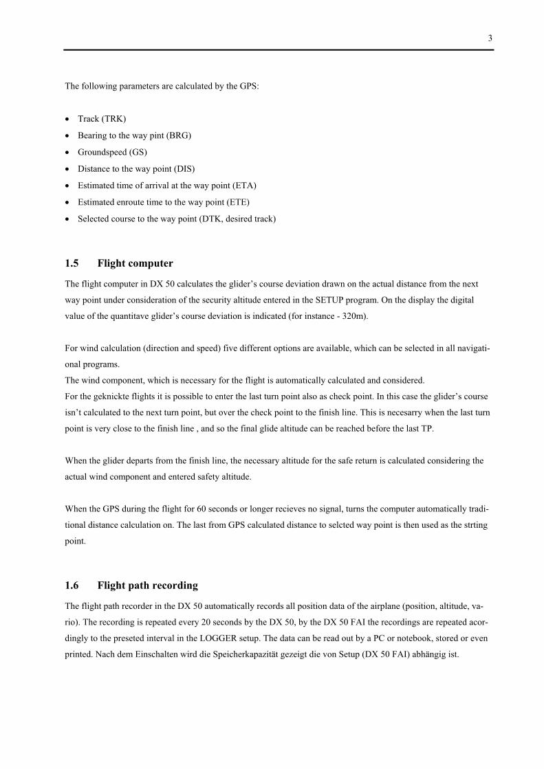
3
The following parameters are calculated by the GPS:
Track (TRK)
Bearing to the way pint (BRG)
Groundspeed (GS)
Distance to the way point (DIS)
Estimated time of arrival at the way point (ETA)
Estimated enroute time to the way point (ETE)
Selected course to the way point (DTK, desired track)
1.5 Flight computer
The flight computer in DX 50 calculates the glider’s course deviation drawn on the actual distance from the next
way point under consideration of the security altitude entered in the SETUP program. On the display the digital
value of the quantitave glider’s course deviation is indicated (for instance - 320m).
For wind calculation (direction and speed) five different options are available, which can be selected in all navigati-
onal programs.
The wind component, which is necessary for the flight is automatically calculated and considered.
For the geknickte flights it is possible to enter the last turn point also as check point. In this case the glider’s course
isn’t calculated to the next turn point, but over the check point to the finish line. This is necesarry when the last turn
point is very close to the finish line , and so the final glide altitude can be reached before the last TP.
When the glider departs from the finish line, the necessary altitude for the safe return is calculated considering the
actual wind component and entered safety altitude.
When the GPS during the flight for 60 seconds or longer recieves no signal, turns the computer automatically tradi-
tional distance calculation on. The last from GPS calculated distance to selcted way point is then used as the strting
point.
1.6 Flight path recording
The flight path recorder in the DX 50 automatically records all position data of the airplane (position, altitude, va-
rio). The recording is repeated every 20 seconds by the DX 50, by the DX 50 FAI the recordings are repeated acor-
dingly to the preseted interval in the LOGGER setup. The data can be read out by a PC or notebook, stored or even
printed. Nach dem Einschalten wird die Speicherkapazität gezeigt die von Setup (DX 50 FAI) abhängig ist.
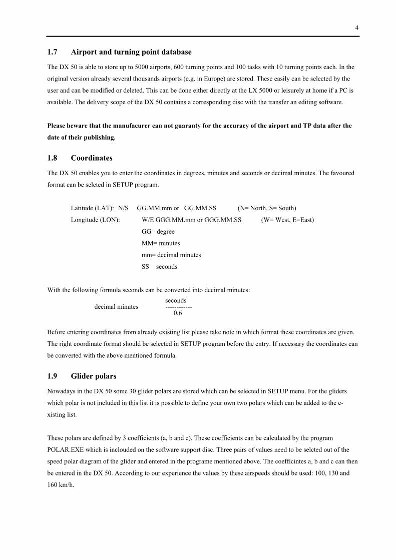
4
1.7 Airport and turning point database
The DX 50 is able to store up to 5000 airports, 600 turning points and 100 tasks with 10 turning points each. In the
original version already several thousands airports (e.g. in Europe) are stored. These easily can be selected by the
user and can be modified or deleted. This can be done either directly at the LX 5000 or leisurely at home if a PC is
available. The delivery scope of the DX 50 contains a corresponding disc with the transfer an editing software.
Please beware that the manufacurer can not guaranty for the accuracy of the airport and TP data after the
date of their publishing.
1.8 Coordinates
The DX 50 enables you to enter the coordinates in degrees, minutes and seconds or decimal minutes. The favoured
format can be selcted in SETUP program.
Latitude (LAT): N/S GG.MM.mm or GG.MM.SS (N= North, S= South)
Longitude (LON): W/E GGG.MM.mm or GGG.MM.SS (W= West, E=East)
GG= degree
MM= minutes
mm= decimal minutes
SS = seconds
With the following formula seconds can be converted into decimal minutes:
seconds decimal minutes= ------------ 0,6
Before entering coordinates from already existing list please take note in which format these coordinates are given.
The right coordinate format should be selected in SETUP program before the entry. If necessary the coordinates can
be converted with the above mentioned formula.
1.9 Glider polars
Nowadays in the DX 50 some 30 glider polars are stored which can be selected in SETUP menu. For the gliders
which polar is not included in this list it is possible to define your own two polars which can be added to the e-
xisting list.
These polars are defined by 3 coefficients (a, b and c). These coefficients can be calculated by the program
POLAR.EXE which is inclouded on the software support disc. Three pairs of values need to be selcted out of the
speed polar diagram of the glider and entered in the programe mentioned above. The coefficintes a, b and c can then
be entered in the DX 50. According to our experience the values by these airspeeds should be used: 100, 130 and
160 km/h.

Seite 5
2 Installation
Please read the following installation instructions carefully through before mounting the device into the glider.
2.1 Mechanical fixing
For the DX 50 a new fixing method of the instrument in the instrument panel has been developed.
The whole instrument can be removed very simply from the front side of the instrument panel. There are special
pneumatical connectors which alove to remove the instrument whitout disconnecting the plastic tubes. The same
holds true for the electrical wireing. That mens that the pilot needs only a few seconds to remove the instrument and
brings it to the scoring office.
prepare the instrument recess according to the drilling plan
fix from behind the instrument holder
mount the tubes on the Ptot, Pst and TE
plug in the antena
2.2 Antenna
The delivered GPS antena has to be mounted in the airplane in such a way that the optical range to the sky is not
obstructed. The cover of the instrument panel in the airplane is the best mounting position. It is also possible to
mont it underneath the instrument cover provided it is not made of carbon fiber reinfoced plastics or metal (e.g.
aluminium). Please pay attention that the antenna is not shielded by metallic parts or by solar panels and that it is
not mounted in the immediate vicinity of the magnetic compass.
It is recommanded to test the receipt of the GPS signal with a provisionally mounted antenna first before mounting
the antena permanently. The antenna should only be mounted after an optimal mountig position has been found.
You can lay the antenna cable according to the following rules:
the antenna cable should not be kinked
it should be laid in as large radii as possible
do not wind up extra antenna cable to a ball or wind it round the antenna
the antenna cable should never be laid close to other current-carying leads or antenna cables
The delivered antenna should not be mounted outside the airplane.
2.3 Pneumatic connection
On the back of the mounting frame there are three pneumatical connectors (static Pst, Pst TE, Total pressure Ptot).
Pst is allways connected to the static source of the glider using TE probe for compensation connect Pst TE to the TE

Seite 6
probe. Ptot is allways connected to the total pressure source of the glider (Pitot). See Figure 1 for details. Beachten
Sie unbedingt die unterschiedliche Anschlußweise bei Düsen- bzw. elektronischer Kompensation!
Figure 1: pneumatic connection
Attemtion:
Do not blow into the pressure connectors of the instrument, because the pressure sensors could be damaged.
2.4 Wiring
All the cables needed for the normal operating of the instrument are inclouded in the pacage:
All the cables are shielded
The two stribed cable ends of the power supply cable have to be connected to the power supply in the glider. If
possible use a supply cable with a large crossection and pay attention to a proper grounding.
The power supply (RED) should be protected with a fuse (1,0 Amp) in any case!!
red end = PLUS
blue end = MINUS/ground
The panel jack of the PC interface can be mounted in the instrument panel. If required the delivered interface cable
to the PC COM port can then be plugged in the panel jack.
The speaker should be connected with the cinch jack to the cable set. The speaker should be as far from the magne-
tic compass as possible because of the possible disturbances of the compass.
The cable labeld SC is used for manual external speed command change over (switch on the stick or flaps).
Ptot
Pst
Pst (TE)
GPS
Versorgung

Seite 7
The cable labeld NMEA will only be used when the external Moving-Map-System is run on the DX 50.
The acurate wiring plan is shown on the beginning of this manual.

Seite 8
3 Operation
The operation of the DX 50 was designed as user friendy and as simple as possible. Flying with the DX 50 is pos-
sible without a long faniliarization.
3.1 Control elements
The control panel of the DX 50 is equiped with 14 key keyboard.

Seite 9
The control elements have the following functions:
Function:
ON switch used to switch the instrument ON
Mode selector the device has 7 different modes, which can be easily selected with +/- keys
Up and down
cusor keys
with this keys you can select the input data (e.g. to scan up and down the alphabet or the
figures from 0 to 9)
Speaker with the combination of this key and the +/- keys you can alter the speaker’s volume
McCready switch use MC key in combination with +/– keys to alter the McCready function
Ballast switch use BAL and +/– keys to alter the ballast entry
ENTER button with the ENTER-button the entered data are confirmed or activated and the menus are
opened…
ESC button
OFF
with the ESC button you can skip input data or return from already selected functions;
if holded for a longer time (few seconds) the instrument will turn OFF
START button to start the programmed tasks (only possible when fling), to store the curent position as
way point (only in TP mode) and to operate the stop-watch (only in POS mode), as well
as to return to the corresponding mode during the editing process. If you push the
START button in the APT navigation program the full APT name will be shorty
displayed in the upper line.
After any button is pushed a short beep is heard !
3.2 Data editing and selction
Editing as well as selcting of data are done the same way in all modes of the DX 50. To reach a high degree of
comfort a simple and especially logical operation of the instrument is used to guarntee a quick familiarization and
an unmistakable operation.
When the instrument is ready for the input of a letter combination, e.g. a TP name the cursor flashes on the first
position of the input field. Now you can select the different letters of the alphabet or figures from 0 to 9 by pushing
the up and down cursor keys. If you push the ENTER button the selcted letter or figure is stored and the cursor
moves to the next position of the input field.
Using the START button the cursor can be moved one position to the left again to correct possible mistakes.
By pushing the ESC button the whole following data block can be skipped. This could be necessary e.g. if you do
not want to push thr ENTER button 4 times to store already indicated signs.
Example:the input of the airfield altitude
After the turning ON the DX 50 the curent airfield altitude should be entered.

Seite 10
The different figures are then selected by up and down cursor keys; do not forget to confirm every chosen value by
pushing ENTER. If the altitude displayed is correct, so you don’t want to change it, then just push ESC to skip the
whole figure block or confirm every figure by pushing thr ENTER button.
Again, here is a short summary:
to confirm an input ! ENTER button
to skip an input ! ESC button
to move the cursor to the left: ! START button
These procedure is the same by all the inputs made.
3.2.1 The wing load adjustment
The actual wing load can be entered in kg/m2, lb/ft2 or as an OVERLOAD in procentage (1.2 equals 20% overlo-
ad). The wanted unit can be selected in the SETUP program.
Example:how to calculate the overload procentage:
The glider polar which should be entered in the DX 50 is based on the wing load of 35 kg/m². But the actual wing
load is 42 kg/m². This calculation should be made:
curent wing load 42kg/m² Overload = ------------------------- = ---------- = 1,2 standard wing load 35kg/m² By this example the value 1,2 (that is 20% increased wing load) should also be put in. Independably of the selected
wing load units the entered value apperas on display.
3.2.2 Input of the McCready values
The input of the McCready values is done by pushing the MC button and by pushing + or - key shortafter, the input
value apperas on display.

Seite 11
4 DISPLAY presentation
The following figures show the display of the DX 50 and the indicated data:
4.1 Glider navigation display 1
The navigation display is the most needed information source of the DX 50. All required information for a precise
navigation to a certain point are shown on this display. All calculated data are related to the way point that is shown
in the first line.
BRG indicates the bearing to the way point
DIS indicates the distance of the glider to the selected way point
GS indicates the ground speed of the glider
TRK indicates the track of the glider
Figure 2: glider navigation display
Wing load (as absolute or relative value) here: relative
McCready value
Final glide deviation altitude: + ->glider too high (over the glide) - ->glider too low (under the gleid)
Integrator indicator
Speed command: PUSH: fly faster PULL: fly slower
Wind direction and its speed
Altimeter (baro-metric) Indicator of the deviation from the Track:
right arrow:course to the WP is to the right left arrow:coures to the WP is to the left - command indicator
Name of the way point
ICAO indicator
Distance to the way point
Bearing to the way point
Track
Type of the way point APT:airport TP:turning point TSK:task

Seite 12
4.2 Graphic display
The graphic display serves as a navigation support in a graphic and alphanumerical form in the APT, TP, und TSK
modes.
The graphic display is second to the navigationt display in the above mentioned modes. The graphic display is cal-
led by pushing the AB button.
The most important data as BRG(B), TRK(T), GS(G) and distance are shown on the right hand side of the disply.
The name of the selected way point appears in the shortened form.
In the gaphic part of the display the current position of the glider is shown in relation to the selected course or to the
selected way point respectively.
The different air space structures are shown all togeather or related to their type fading in or out (see SETUP).
Two different glider symbols are available and are configured in the SETUP program.
Figure 3: Graphic display
If there aren’t enough satelites for the navigation in the lower part of the display the warning GPS BAD is display-
ed. The ZOOM function (“ +” or “- ” button ) enables you to select the scale from 200 km to 100, 50, 20, 10, 5
and 2 km. The selected scale value is shown in the left bottom corner of the display. In the TASK mode ‘Z’ is
displayed for ZOOM and the TSK, LEG or FS (photo sector) for the presented mode. By pushing the AB button the
belonging navigation display is switched on.
Type selected way point: APT: airport TP: turn point TSK: task
Way point
Airspace structures if selected in SETUP
Course line Glider symbol
Zoom factor: e.g. 100km means that the width of the display is 100km
Short name of the selected way point
Bearing (BRG)
Distance (DIS)
Track (TRK)
Ground speed (GS)

Seite 13
4.5.3 Navigation display
All the required information for a precise navigation to a certain point are shwn on the navigation display as well as
on the glider navigation display described above. Some specific glider information are added to the bottom of a
diaplay as a scale which shows the lateral deviation from the selected course. The scale can be altered by pushing
the + or - keys (only when the navigation display active is). The function can be compared with the OBS and CDI
of a VOR receiver.
All calculated and displayed data are related to the way point or airfield that is shown in the first line.
DTK This value can be selected by “ +” or “ -” button. It corresponds to the OBS of a VOR receiver.
With a DTK a course can be selected. It is not adjustable in the TSK mode!!
CDI indicates the lateral deviation from the selected course (DTK)
XTE indicates the lateral deviation from the selected course (DTK) in km, nm or ml
Figure 4: Navigation display
This display can be turned off in SETUP program with password (PAGE3) if not needed.
By pressing the AB button in the navigation menu the coresponding arrival display is shown.
Bearing to the way point
Track
Ground speed
Distance to the way point
Selected course (DTK), adjustable with ZOOM knob (not in the TSK mode)
Lateral deviation indi-cator (CDI)
Cross Track Error (XTE)
Name of the way point
ICAO indicator
Type of the way point: APT: airport TPT: turning point TSK: task

Seite 14
4.3 Arrival display
The arrival display informs you about the arrival data of the currently aproached way point in the APT, TP and TSK
modes. The following data are displayed:
ACT.T current time
ETA estimated time of arrival
ETE estimated time enroute
W wind speed and direction
V battery valtage
TC Traffic Circuit altitude
Figure 5: Arrival display
By pressing the AB button the INFO display is shown (holds true only if the airfield is selected as the next way
point).
Name of the way point
ICAO indicator
Type of the way point: APT: airport TP: turning point TSK: task
Current time
Estimated time of arrival at the
WP (ETA); estimated enroute
time to the WP (ETE)
Battery voltage
Traffic circuit altitude
Temperature (exter-naly measured)
Wind direction and speed
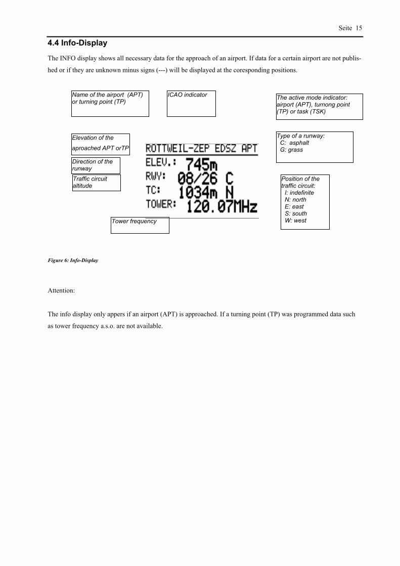
Seite 15
4.4 Info-Display
The INFO display shows all necessary data for the approach of an airport. If data for a certain airport are not publis-
hed or if they are unknown minus signs (---) will be displayed at the coresponding positions.
Figure 6: Info-Display
Attention:
The info display only appers if an airport (APT) is approached. If a turning point (TP) was programmed data such
as tower frequency a.s.o. are not available.
Name of the airport (APT) or turning point (TP)
ICAO indicator The active mode indicator: airport (APT), turnong point (TP) or task (TSK)
Elevation of the
aproached APT orTP
Direction of the runway
Traffic circuit altitude
Tower frequency
Type of a runway: C: asphalt G: grass
Position of the traffic circuit: I: indefinite N: north E: east S: south W: west

Seite 16
5. Menu structure
The following figure shows the structure of the different program modes of the DX 50.The program modes can be
selected by using the MODE button and short after the “ + ” or “ - ” key (regardless of which mode was selected
before).
Figure 7: Structue of the program moes
The mode key stays active for a short time after it has been pushed, so you need to release the mode key and then
press the + or - key to make the selection. It is also possible skipp some modes by pressing +/- keys repetedly. The
selected mode becomes active at once. There are seven different modes available:
POSITION Indication of the current position (coordinates), current time, date and stop-watch.
NEAR APT In this mode the distance and the course to the 10 most close airports is displayed.
APT Used for the direct aproach to the airport or to edit the airport database
TP Used for the direct aproach to the TP or to edit the TP database
TSK Used to fly the previously programmed task as also to edit the task database
In the APT, TP, and TSK modes the WIND calculations and TEAM function menues are
available.
STATISTICS The DX 50 offers you two different types of statistics:
during the flight statistics and the statistics after the flight with the log book.
SETUP In setup program the system setup is made.
The APT and TP modes are almost identical. The difference is that in the APT mode all the data relate to the pro-
grammed airport but to the programmed turning point in the TP mode (which can also be an airport).
SETUP POS NEAR
AIRPORT
APT TP TSK STAT
MODE + or -
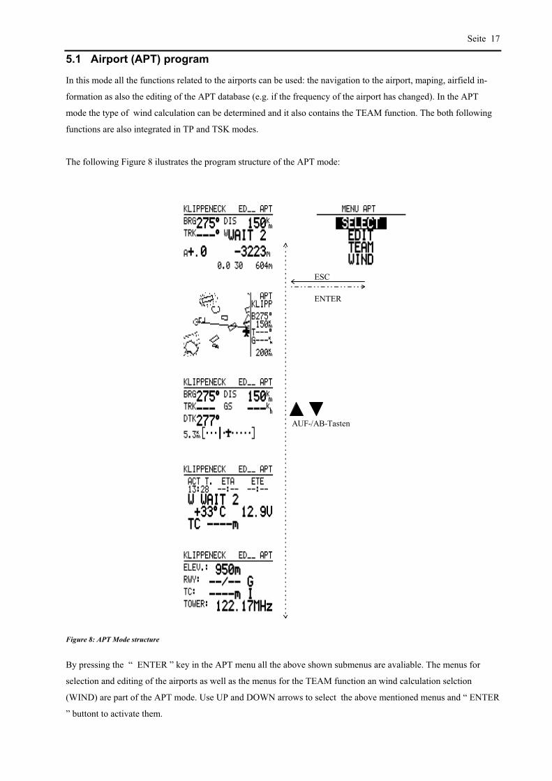
Seite 17
5.1 Airport (APT) program
In this mode all the functions related to the airports can be used: the navigation to the airport, maping, airfield in-
formation as also the editing of the APT database (e.g. if the frequency of the airport has changed). In the APT
mode the type of wind calculation can be determined and it also contains the TEAM function. The both following
functions are also integrated in TP and TSK modes.
The following Figure 8 ilustrates the program structure of the APT mode:
ESC
ENTER
AUF-/AB-Tasten
Figure 8: APT Mode structure
By pressing the “ ENTER ” key in the APT menu all the above shown submenus are avaliable. The menus for
selection and editing of the airports as well as the menus for the TEAM function an wind calculation selction
(WIND) are part of the APT mode. Use UP and DOWN arrows to select the above mentioned menus and “ ENTER
” buttont to activate them.

Seite 18
Example: Selection of an APT:
After selcting the APT program with the MODE button the APT menu is activated by pressing the “ ENTER ” key.
With the arrows keys the menu SELCT is selected and with ENTER key activated. Now there are two possibilities
for search for the airfields:
a) Search for ICAO indicator b) Search for name
Now enter the full ICAO indicator of the
airport (every letter has to be confirmed by
ENTER button).
Skip the input of the ICAO indicator by pushing the ESC
button or pushing the ENTER button 4 times.
The DX 50 is searching the airport using
the ICAO indicator and returns direct to the
glider NAV display with the NAV data of
the desired APT displayed.
Select the country of the disired airport by the UP/DOWN
keys and push the ENTER button to confirm selection.
Now you can enter the first four letters of the desired
airport using the arrow key and ENTER key for confirma-
tion.
You will now find one or several airports in the bottom
line of the display that start with the four entered letters.
If more than one airport is indicated the desired can be
selected by UP/DOWN keys and activated by pushing
ENTER.
The NAV data of the selected airfield are then displayed
in the glider NAV menu.
5.1.1 TEAM
The TEAM menu enables group flights of two or more gliders; e.g. when you lose your partner out of sight or when
you want to meet him on your way. With the TEAM menu you can follow your partners under condition that all the
gliders are equiped with the GPS instruments (preferable with the DX 50) and are flying to the same way point.
Both partners have to select the same way point. The serched partner-B has to tell the partner-A his bearing and the
distance to the selected way point by radio. These values are then entered by partner-A in the mode APT/menu
TEAM of the DX 50. On the glider navigation display are then shown the navigation data directly to the partner-B.
5.1.2 WIND
The wind can be calculated (considered) in 4 different ways.
In the APT, TP or TSK menus the WIND menu can be selected. The following options are available:
FIX manual input of a fixed value (speed and direction)

Seite 19
(in SETUP program you are able to select different units for wind’s speed)
The resulted wind component will be considered by all the calculations made.
GS Here the wind is determined over the glider’s ground speed. This enables you to circle with the
constant speed (IAS).
POS Works only by climbing (minimum six turns to get the wind)
COMB. Special algorithm where TAS, GS, TRK are taken in calculation and the result is the wind. The m
is functionig during the climbing as well as by straight flight where some track deviations are ma
The pilot has to chose the desired wind calculation. The pilot is able to change the method whenever he wants, only
one can be activated at the time.
Please take attention that the GS and POS methots can only be selected while circling and COMB only during the
straight flight. If you select the FIX method your wind component is constant and isn’t calculated.
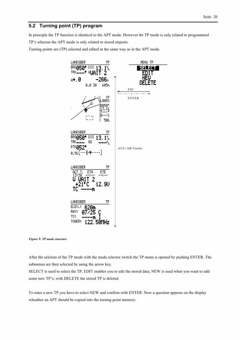
Seite 20
5.2 Turning point (TP) program
In principle the TP function is identical to the APT mode. However thr TP mode is only related to programmed
TP’s whereas the APT mode is only related to stored airports.
Turning points are (TP) selected and edited in the same way as in the APT mode.
ESC
ENTER
AUF-/AB-Tasten
Figure 9: TP mode structure
After the selction of the TP mode with the mode selector switch the TP menu is opened by pushing ENTER. The
submenus are then selected by using the arrow key.
SELECT is used to select the TP; EDIT enables you to edit the stored data; NEW is used when you want to add
some new TP’s; with DELETE the stored TP is deleted.
To enter a new TP you have to select NEW and confirm with ENTER. Now a question apperas on the display
wheather an APT should be copied into the turning point memory:
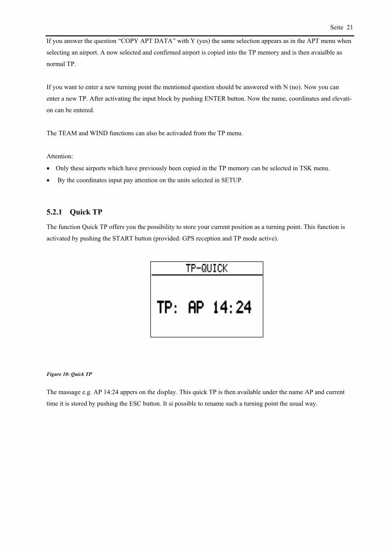
Seite 21
If you answer the question “COPY APT DATA” with Y (yes) the same selection appears as in the APT menu when
selecting an airport. A now selected and confirmed airport is copied into the TP memory and is then avaialble as
normal TP.
If you want to enter a new turning point the mentioned question should be answered with N (no). Now you can
enter a new TP. After activating the input block by pushing ENTER button. Now the name, coordinates and elevati-
on can be entered.
The TEAM and WIND functions can also be activaded from the TP menu.
Attention:
Only these airports which have previously been copied in the TP memory can be selected in TSK menu.
By the coordinates input pay attention on the units selected in SETUP.
5.2.1 Quick TP
The function Quick TP offers you the possibility to store your current position as a turning point. This function is
activated by pushing the START button (provided: GPS reception and TP mode active).
Figure 10: Quick TP
The massage e.g. AP 14:24 appers on the display. This quick TP is then available under the name AP and current
time it is stored by pushing the ESC button. It si possible to rename such a turning point the usual way.

Seite 22
5.3 Task (TSK) program
In the TASK (TSK) mode up yo 100 tasks with 10 way point each can be stored in the DX 50. The stored tasks can
be displayed graphically on the sreen. All programmed turning points can be used as points for a task. If airports
should be programmed into a TASK they have to be copied into the TP memory first.
ESC
ENTER
AUF-/AB-Tasten
Figure 11: TSK Mode structure

Seite 23
There are three different possibilities to display the task graphically:
Figure 12: TSK graphic modes
By using thr + or - keys the above mentioned graphic modes can be selected as long as the instrument is in the TSK
mode. The scale of these three graphic modes can not be changed as it is possible in the APT or TP mode.
Either the whole task, the whole active leg or the active pgoto sector can be shown on the display. Es kann entwe-
der die gesamte Aufgabe (TSK), der gesamte aktive Schenkel (LEG), oder der aktive Fotosektor(FS), eingeblendet
werden. The active photo sector means the next sector which will be flown to. The show glider indicates the current
position related to the task.
5.3.1 Selection of a TASK
After selcting the TSK mode with MODE button the TSK menu is activated by pushing ENTER. The option
SELECT should be selected and confirmed with ENTER. With UP and DOWN keys you can browse through all
100 possible tasks. The number of the current task is shown on the display with the programmed way points below.
If points are not programmed within the task the message NOT PROG appers. If you want to activate the displayed
task you have to push the ENTER button. The selected task is now active.
On the glider navigation display the first tuning point (normally designated Nr. 0) will be considered as a start point.
That is normally the starting airfield but can also be a TP out of the airfield.
The information for aproach to the first way point aren’t shown until the start of the task.

Seite 24
5.3.2 Change of a TASK (TSK EDIT)
In TSK EDIT menu you can change alredy programmed tasks that means that you have the possibility to change
TP’s, to skip or delete one or more TP’s or invert the task as well. The last way point before the finish can also be
entered as a check point.
After selecting the task in the glider NAV menu the TSK menu has to be reopened by pushing ENTER. By
UP/DOWN keys the EDIT menu has to be selected and confirmed by ENTER.
The DX 50 dispalys a question wheather the task should be inverted or not. After answering Y or N the total di-
stance of a task and the distances and courses of the single legs are displayed.
The last turning point before the final point can be programmed as a check point by using ENTER and UP/DOWN
keys.
If you place the cursor by arrow key to the desired turning point and activate it by pushing ENTER, the submenu in
which now SELECT, INSERT or DELETE can be selected opens.
By openig the SELECT menu you will be asked to enter the first four letters of the TP name. The matching turning
points are displayed and are available for your selection. By using the UP/DOWN keys and ENTER the desired TP
will be selected and activated.
By pushing the ESCAPE button you will be able to select between all the stored turning points in the alphabetical
order.
a) Search for a name b) Browsing tgrough all TP´s
Enter the first four letters of the TP in the usual way at
the position of the four stars and confirm each time
with ENTER.
Instead of entering the name push ESC button once.
Now all the programmed TP’s appear in alphabetical
order in the line below. The selction is made by
UP/DOWN keys and ENTER key.
In TP memory coied airports have to be searched by their names not by their ICAO indicator.
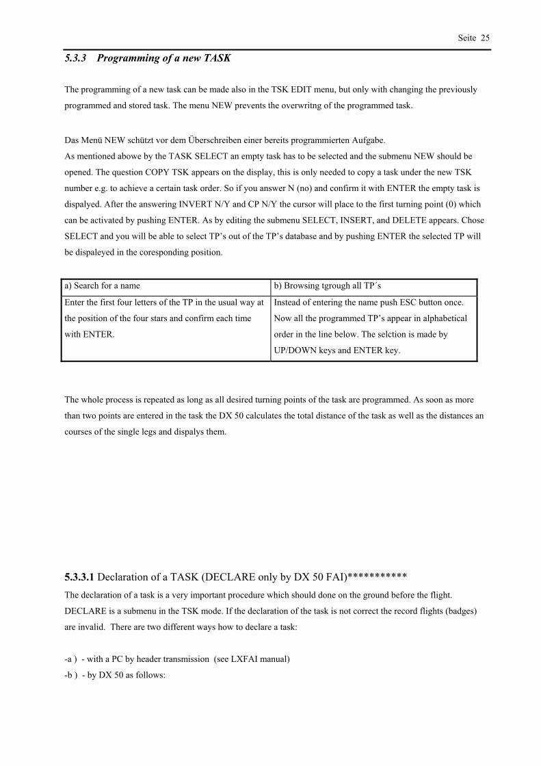
Seite 25
5.3.3 Programming of a new TASK
The programming of a new task can be made also in the TSK EDIT menu, but only with changing the previously
programmed and stored task. The menu NEW prevents the overwritng of the programmed task.
Das Menü NEW schützt vor dem Überschreiben einer bereits programmierten Aufgabe.
As mentioned abowe by the TASK SELECT an empty task has to be selected and the submenu NEW should be
opened. The question COPY TSK appears on the display, this is only needed to copy a task under the new TSK
number e.g. to achieve a certain task order. So if you answer N (no) and confirm it with ENTER the empty task is
dispalyed. After the answering INVERT N/Y and CP N/Y the cursor will place to the first turning point (0) which
can be activated by pushing ENTER. As by editing the submenu SELECT, INSERT, and DELETE appears. Chose
SELECT and you will be able to select TP’s out of the TP’s database and by pushing ENTER the selected TP will
be dispaleyed in the coresponding position.
a) Search for a name b) Browsing tgrough all TP´s
Enter the first four letters of the TP in the usual way at
the position of the four stars and confirm each time
with ENTER.
Instead of entering the name push ESC button once.
Now all the programmed TP’s appear in alphabetical
order in the line below. The selction is made by
UP/DOWN keys and ENTER key.
The whole process is repeated as long as all desired turning points of the task are programmed. As soon as more
than two points are entered in the task the DX 50 calculates the total distance of the task as well as the distances an
courses of the single legs and dispalys them.
5.3.3.1 Declaration of a TASK (DECLARE only by DX 50 FAI)***********
The declaration of a task is a very important procedure which should done on the ground before the flight.
DECLARE is a submenu in the TSK mode. If the declaration of the task is not correct the record flights (badges)
are invalid. There are two different ways how to declare a task:
-a ) - with a PC by header transmission (see LXFAI manual)
-b ) - by DX 50 as follows:

Seite 26
Select a task in a usual way.
With copy a selected task can be copied or after N (no) edited. The DX 50 task doesn’t consider the TAKE OFF
point as a start point so this should be entered. After pushing ENTER button appears a window with SELECT,
INSERT and DELETE now you can edit the selected task if you want. The same holds true for LANDING.
After pushing ESC the window closes, the task is declared and a message TASK DECLARED appears. During the
flight many different tasks can be selected and flown, but in FAI logger the only active task is the declared task.
If the task is alredy declared the following message appears after the selecting DECLARE:
If the answer is N (no) the previously in logger declared task is displayed and you can return to the TSK menu by
pushing ESC. If the answer is Y (yes) the curent selected task is displayed that means the last declared task has been
altered.
IMPORTANT!
After every landing the task must be declared again although the task stays the same.
The LXFAI program enables you to declare task on your PC. The task should be correctly defined in FLIGHT
INFO menu and then transmited to the DX 50. It is then automatically declared and the TSK DECLARE is not
necessary.
5.3.4 Deletion of a TASK (DELETE)
You can delete a task that has been selected as active before. To delete the whole task select DELETE menu. BY
chosing Y (yes) the deletion process is confirmed, by chosing N (no) the deletion process is terminated.

Seite 27

Seite 28
5.3.5 Flying with a TASK
When using the TSK mode note the following remarks:
The corresponding task must have been programmed and activated.
It is recomanded to perform a task chech before the flight. This can be done by using the TSK subprogram TSK
EDIT. In this program all leg distances, all leg courses and the total distance of the task are calculated and
displayed. Possible coordinate or programming errors of the turning points can now be recognized and corrected
in time.
A programmed task always has to be started manually when passing the start point by holding the START but-
ton at least for a second.
However the instrument switches automatically to the next leg of the task when passing the way point sector.
When flying in the TSK mode it can be quit any time to continue the flight in another mode (e.g. TP, APT, or
Near Airport). However shortly before reaching the way of final point you have to return to the TSK mode be-
cause otherwise the statistic documentatioin is incomplete.
As long as the task is not started the DX 50 dispalys all flight data (course, distance etc.) related to the first entered
point of the task.
5.3.6 Starting of a TASK
The pfhotosector dimesions as also the size of a radius (Start, TP or Finish radius) and thus the dimension of the
coresponding sectors can be selected in the SETUP TSK menu.
Fotosektor
Cylinder
Radius
Figure 13: Rounding modes
To start a task or to chane to the next leg of a task when rounding a way point the START button has to be pushed
in the following manner:
Photosector/Cylinder
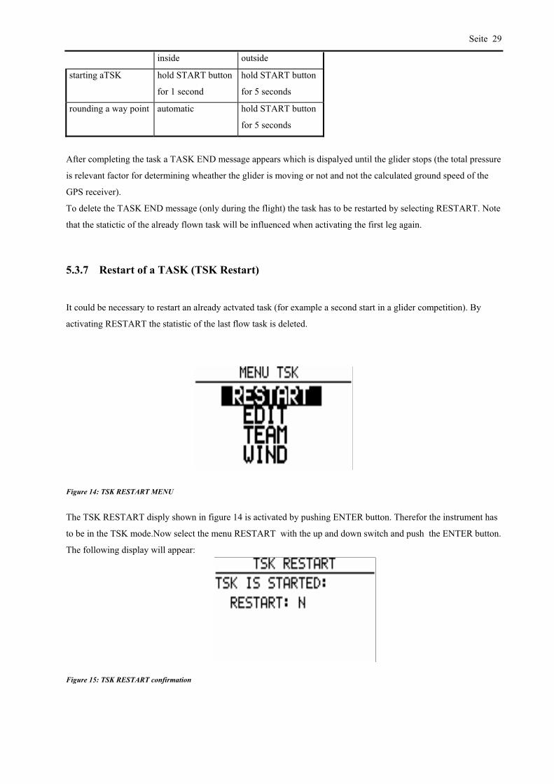
Seite 29
inside outside
starting aTSK hold START button
for 1 second
hold START button
for 5 seconds
rounding a way point automatic hold START button
for 5 seconds
After completing the task a TASK END message appears which is dispalyed until the glider stops (the total pressure
is relevant factor for determining wheather the glider is moving or not and not the calculated ground speed of the
GPS receiver).
To delete the TASK END message (only during the flight) the task has to be restarted by selecting RESTART. Note
that the statictic of the already flown task will be influenced when activating the first leg again.
5.3.7 Restart of a TASK (TSK Restart)
It could be necessary to restart an already actvated task (for example a second start in a glider competition). By
activating RESTART the statistic of the last flow task is deleted.
Figure 14: TSK RESTART MENU
The TSK RESTART disply shown in figure 14 is activated by pushing ENTER button. Therefor the instrument has
to be in the TSK mode.Now select the menu RESTART with the up and down switch and push the ENTER button.
The following display will appear:
Figure 15: TSK RESTART confirmation

Seite 30
If you answer the question RESTART with Y (yes) your task will be reset, that means that first entered point of the
task will appear as navigation point on the TSK navigation display. Now the task has to be restarted e.g. by second
start when passing the start line or photosector by pushing ENTER button.
IMPORTANT: RESTART has no influence on the declared task in the FAI Logger.
5.3.8 Setup program
In the setup program all parameters that are necessary for the later use of the DX 50 can be programmed.
Figure 16: SETUP mode
The abowe figure shows the display which appers after selecting the SETUP menu. The following diagram shows
the particular submenus of the SETUP mode and their mening or their activation respectively:
QNH RES ENTER ! ESC
Input of: QNH (for altitude correction during the flight) ALT. R = reserve altitude for the final glide BUGS = the polar deterioration because of midges (BUGS) in % entered in 2,5% steps to max. 30%
LOGGER ENTER ! ESC
Input of the FAI Logger parameters (only by DX50 FAI)
INIT ENTER ! ESC
Input of: Vario Filter Vario integration time ( 10, 20 or 30 sec. ) Vario range selection ( 2.5, 5 or 10 m/s) Speed command audio dead area ( 0 to +-2 m/s ) Autom. Vario-/Speed command turn on: OFF / GPS or TAS
DISPLAY ENTER ! ESC
LCD contrast ( 0 to 100% )
PC ENTER ! ESC
PC communication
PASSWORD ENTER ! ESC
Input of the Password (96990), then skipping into the SETUP PASSWORD submenu
Figure 17: Structure of the SETUP menu
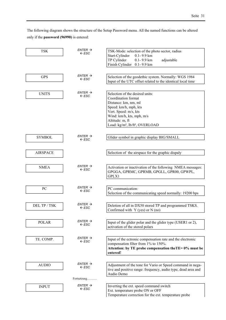
Seite 31
The following diagram shows the structure of the Setup Password menu. All the named functions can be altered
only if the password (96990) is entered:
TSK ENTER ! ESC
TSK-Mode: selection of the photo sector, radius Start-Cylinder 0.1- 9.9 km TP Cylinder 0.1- 9.9 km adjustable Finish Cylinder 0.1- 9.9 km
GPS ENTER ! ESC
Selection of the geodethic system. Normally: WGS 1984 Input of the UTC offset related to the identical local time
UNITS ENTER ! ESC
Selection of the desired units: Coordination format Distance: km, nm, ml Speed: km/h, mph, kts Vert. Speed: m/s, kts Wind: km/h, kts, mph, m/s Altitude: m, ft Load: kg/m², lb/ft², OVERLOAD
SYMBOL ENTER ! ESC
Glider symbol in graphic display BIG/SMALL
AIRSPACE Selection of the airspace for the graphic dispaly
NMEA ENTER ! ESC
Activation or inactivation of the following NMEA messages: GPGGA, GPRMC, GPRMB, GPGLL, GPR00, GPWPL, GPLX1
PC ENTER ! ESC
PC communication: Selection of the communicating speed normally: 19200 bps
DEL TP / TSK ENTER ! ESC
Deletion of all in DX50 stored TP and programmed TSKS. Confirmed with Y (yes) or N (no)
POLAR ENTER ! ESC
Input of the glider polar and the glider type (USER1 or 2), activation of the stored polars
TE. COMP. ENTER ! ESC
Input of the ectronic compensation rate and the electronic compensation filter from 1% to 150%. Attention: by TE probe compensation theTE= 0% must be
entered!
AUDIO ENTER ! ESC
Adjustment of the tone for Vario or Speed command in nega-tive and positive range: frequency, audio type, dead area and Audio Demo
Fortsetzung.............
INPUT ENTER ! ESC
Inverting the ext. speed command switch Ext. temperature probe ON or OFF Temperature correction for the ext. temperature probe

Seite 32
INDICATOR Function selection for the LCD vario indicator
PAGE 1 ENTER ! ESC
Selection of the shown glider navigation display 1 or 2
PAGE 3 ENTER ! ESC
Navigation display ON/OFF
Figure 18: Structure of the SETUP PASSWORD menu
5.3.8 QNH RES
Here the new QNH can be entered (when switching ON the DX 50 the actual QNH was entered) this is needed if
during a long flight the QNH changes. After the input of the new QNH value the electronic altimeter automatically
considers the new value in calculations so the correct altitude is displayed.
The input of the reserve altitude is needed to reach the selected airfield on a safe altitude. This altitude is added to
the absolute airfield elevation.
5.3.9 LOGGER (only by DX50 FAI)
All the adjustments influence only the FAI Logger and have no influence on the flight.
The main menu has 4 submenus:
FLIGHT INFO Pilot and glider data
LOGTIME Logging time interval selection
(I) RECORD Adjustment of the extra parameters which are shown (not necessary)
(J) RECORD Adjustment of the extra parameters which are shown (not necessary)
The shortenings for the (I) and (J) RECORD:
GSP ground speed
IAS indicated air speed
TAS true air speed
TRM magnetic track
HDT true heading
HDM magnetic heading

Seite 33
TRT true track
TEN total energy
WDI wind direction
WVE wind velocty
5.3.10 INIT
In the INIT menu you can enter the following parameters:
VARIO FILT. Vario filter
VARIO INT. The selection of the integration time of the interval integrator (normal value: 20 Sek.)
VARIO RNG. Vario range adjustment (2.5, 5 and 10 m/s)
TAB Audio dead area by SC (range from 0 to "2m/s)
AUTO SC
GPS
OFF
100 kmh
Activation of the automatic vario/speed command switch
When circling switches the GPS from speed command to vario.
The switching on is achieved by an external switch (on stick or flaps)
The switching on depends on the speed (adjustable from 100- 160 km/h)
5.3.11 DISPLAY (graphic display)
Here you can select the display contrast (from 0 to 100%), the view angle and the light relation.
5.3.12 PC
In this menu you can transfer data from PC or notebook to the DX 50 or read it from DX 50. Therefor the LXFAI
program should be installed and the right connect cable should be applied (see LXFAI manual).
On the PC the menu TRANSFER has to be opened and the menu PC in the DX 50. With ENTER the timeout from
0 to 9 seconds is counted. If in this time the connection is established the following note appears on the display:
CONNECT
The data transfer is now possible. All the operations are made on the PC. After the transmission has ended the ESC
button on the PC has to be pushed to break the connection. The timeout appears again. The SETUP PC menu is
automatically closed.
If the connection isn’t possible the time will run out and the PC menu will be closed. For all other infirmation about
the data transfer see description of the LXFAI program.
5.3.13 PASSWORD
The menu PASSWORD enables you to adjust some other data which are placed in different submenus (glider and
pilot data …).
This data are secured with PASSWORD:
This password can not be changed:
96990
After the entry of this combination the submenus are displayed:

Seite 34
5.3.14 TSK
The selection of the mode of the task start and the radius around the way point inside of which the next leg of the
task is started.
There are two different modes::
Cylinder
Fotosektor
The cylinder radius can be selected (from 0.1 to 9.9 km).
5.3.15 GPS
The GPS receiver operates allways with UTC (before GMT). In this submenu for the time dispaly a time offset can
be entered. Example:
UTC+0: the UTC is shown
UTC+1: the c.e.t. during winter is shown (MEZ= UTC +1 )
UTC+2: the c.e.t. during summer is shown (MESZ= UTC +2 ) etc.
The GPS DATUM is standrdly shown in WGS 1984. This option enables to adapt the coordination system of the
GPS to the Earth. This should not be changed in order to get the right position data.
5.3.16 UNITS
In the submenu UNITS the different forms and units for the fly data presentation can be selected:
Coordinates of the TP’s in dezimal minutes or seconds
DISTANCE: km, nm, ml
SPEED: km/h, kts, mph
Climbing/descending (VER.SPEED): m/s, kts
WIND: km/h, kts, mph, m/s
ALTITUDE: m, ft
WINGLOAD kg/m², lb/ft², OVERLOAD
5.3.17 SYMBOL
In this submenu the glider symbol size can be altered.
5.3.18 AIRSPACE
In the AIRSPACE submenu the airspace info which are shown on the graphic dispaly can be selected:
AIRSPACE: DISABLE/ ENABLE
CTR Zones
R, P, D Zones
TMA Zones
TRA- Zones

Seite 35
TIZ- Zones
All the declared airspace data can be dispalayed separately or togeather. The function AIRSPACE can be complete-
ly disabled.
5.3.19 NMEA
In the NMEA menu the NMEA0183 data string can be configured. This string is needed for the connection of spe-
cial devices such as HandyMap. The NMEA data strings can be enabled or disabled. Which data srings are needed
for the coresponding external device depends on the manufacturer. If on the NMEA interface no ext. devices are
connected then all the NMEA data strings can be disabled.
5.3.20 PC (Adjustments)
In the submenu PC the communicaton bauderate is selected. The default value is 19200. The communication is
possible only when the two devices don’t differ in the boudrate value.
DEL TP/TSK
Within this submenu you are able to delete all the programmed TP’s or TASKS. This happens if the question
“DELETE ALL TP AND TSK:” is answered with Y (yes). The airport database stored in the DX 50 won’t be alte-
red.
POLAR
In the POLAR menu the speed polars of some 30 gliders are stored, which can be easily selected and activated.
It is also possible to enter the two user defined polars.
Under the “min. load” the wing load on which the polar is based should be entered.

Seite 36
5.3.21 TE COMP.
In this submenu the type of electronic compensation and its value can be selected. The default value is set at 0 %.
Please pay attention:
By the TE probe compensation the compensation value of 000% should be entered.
If electronic compensation is wanted the desired values can be entered in TE COMP.
The preset of the TE values for the specific glider type is not possible, because the optimal electronic compensation
depends on many different factors. The exact setup can be made only empirically during the test flight in calm air.
The following flight conditions are necessary for the optimal compensation:
Absolutly calm air
The DX 50 should be in the Vario mode (no SC automatic)
Start the SETUP program and open the menu TE COMP.
Accelerate to aproximately 160 km/h and hold the speed constnt for some 20 seconds.
Then slowly pull up to reach 80 km/h. By the optimal TE compensation the variometer should display the polar
descending. ?????
If the vario shows higher descending then the variometer is over compensated (the TE value should be lowered).
If the vario by pull up a higer climbing (by under compensation) the TE value should be higer.
This procedure should be repeated till the optimal compensation is achieved.
The valid values range from 1 to 150 %.
The filter values can range from 0 to 9.
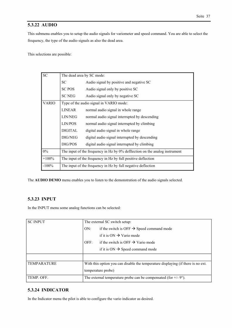
Seite 37
5.3.22 AUDIO
This submenu enables you to setup the audio signals for variometer and speed command. You are able to select the
frequency, the type of the audio signals as also the dead area.
This selections are possible:
SC The dead area by SC mode:
SC Audio signal by positive and negative SC
SC POS Audio signal only by positive SC
SC NEG Audio signal only by negative SC
VARIO Type of the audio signal in VARIO mode:
LINEAR normal audio signal in whole range
LIN/NEG normal audio signal interrupted by descending
LIN/POS normal audio signal interrupted by climbing
DIGITAL digital audio signal in whole range
DIG/NEG digital audio signal interrupted by descending
DIG/POS digital audio signal interrupted by climbing
0% The input of the frequency in Hz by 0% defllection on the analog instrument
+100% The input of the frequency in Hz by full positive deflection
-100% The input of the frequency in Hz by full negative deflection
The AUDIO DEMO menu enables you to listen to the demonstration of the audio signals selected.
5.3.23 INPUT
In the INPUT menu some analog functions can be selected:
SC INPUT The external SC switch setup:
ON: if the switch is OFF Speed command mode
if it is ON Vario mode
OFF: if the switch is OFF Vario mode
if it is ON Speed command mode
TEMPARATURE With this option you can disable the temperature displaying (if there is no ext.
temperature probe)
TEMP. OFF. The external temperature probe can be compensated (for +/- 9°).
5.3.24 INDICATOR
In the Indicator menu the pilot is able to configure the vario indicator as desired.
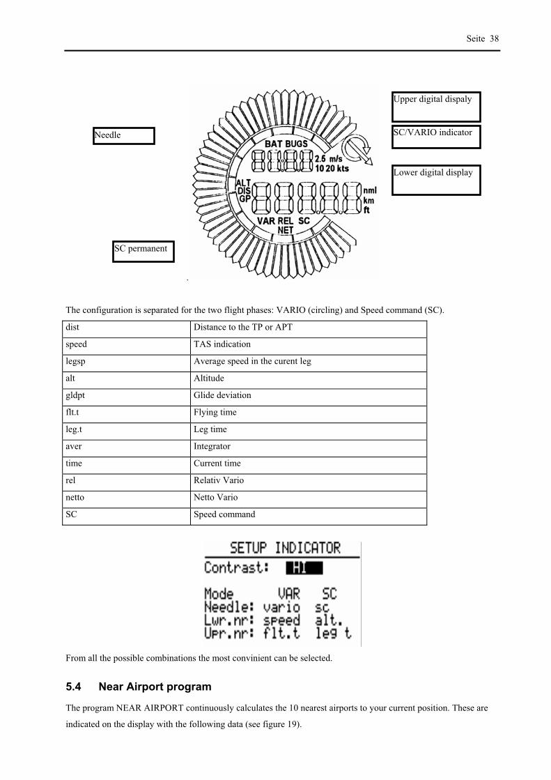
Seite 38
.
The configuration is separated for the two flight phases: VARIO (circling) and Speed command (SC).
dist Distance to the TP or APT
speed TAS indication
legsp Average speed in the curent leg
alt Altitude
gldpt Glide deviation
flt.t Flying time
leg.t Leg time
aver Integrator
time Current time
rel Relativ Vario
netto Netto Vario
SC Speed command
From all the possible combinations the most convinient can be selected.
5.4 Near Airport program
The program NEAR AIRPORT continuously calculates the 10 nearest airports to your current position. These are
indicated on the display with the following data (see figure 19).
Needle
Upper digital dispaly
Lower digital display
SC permanent
SC/VARIO indicator
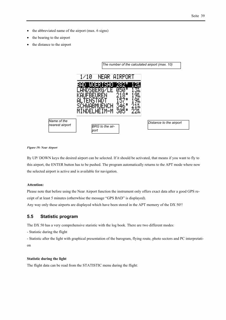
Seite 39
the abbreviated name of the airport (max. 6 signs)
the bearing to the airport
the distance to the airport
Figure 19: Near Airport
By UP/ DOWN keys the desired airport can be selected. If it should be activated, that means if you want to fly to
this airport, the ENTER button has to be pushed. The program automatically returns to the APT mode where now
the selected airport is active and is available for navigation.
Attention:
Please note that before using the Near Airport function the instrument only offers exact data after a good GPS re-
ceipt of at least 5 minutes (otherwhise the message “GPS BAD” is displayed).
Any way only these airports are displayed which have been stored in the APT memory of the DX 50!!
5.5 Statistic program
The DX 50 has a very comprehensive staristic with the log book. There are two different modes:
- Statistic during the flight
- Statistic after the light with graphical presentation of the barogram, flying route, photo sectors and PC interpretati-
on
Statistic during the light
The flight data can be read from the STATISTIC menu during the flight:
Distance to the airport BRG to the air-port
Name of the nearest airport
The number of the calculated airport (max. 10)

Seite 40
The following parameters are displayed:
Start time
Duration
Variometer (digital averager and portion of circling)
After pushing the AB button the leg statistic is displayed
TSK 00/1 means that the 1. leg statistic of task 00 is displayed.
Time The arrival time (time when the TP was reached). If the time isn’t displayed the TP hasn’t been reached yet
(means that the current leg statistic is displayed).
Duration The duration of the leg.
Statistic after the flight
This statistic is official for the FAI regulations and is available some 5 minutes after the landing.
IMPORTANT!
The FAI regulations require a straight line by barogram flight and ending. ????? Therefor it is recomman-
ded to switxh ON the DX 50 5 minutes before the start and not to switch it OFF for 5 minutes after the lan-
ding. All the procedures are surely finished when this message (only by DX 50 FAI) appears:
CALCULATING
SECURITY
After appearence of this message the statistic is available. If this procedure is not respected and the DX 50 is
switched OFF immediadely, this procedure will be repeated after switching it ON again and the data will be
stored.

Seite 41
In the DX 50 Statistic menu the LOGBOOK will be presented.
By using the UP/DOWN keys you are able to select the desired flight. After pushing ENTER the message PLEASE
WAIT is dispalyed and after pushing ENTER again the following data are displayed:
After selecting the ROUTE option the flight route is displayed (it may take few seconds)
The same holds true also for the barogram (ROUTE menu is closed
by ESC and HEIGHT should be activated)
After the flight statistic is activated the DX 50 calculates the TASK (may last few seconds).
If no task is flown then also the task statistic is not avaliable and
the following message appears:
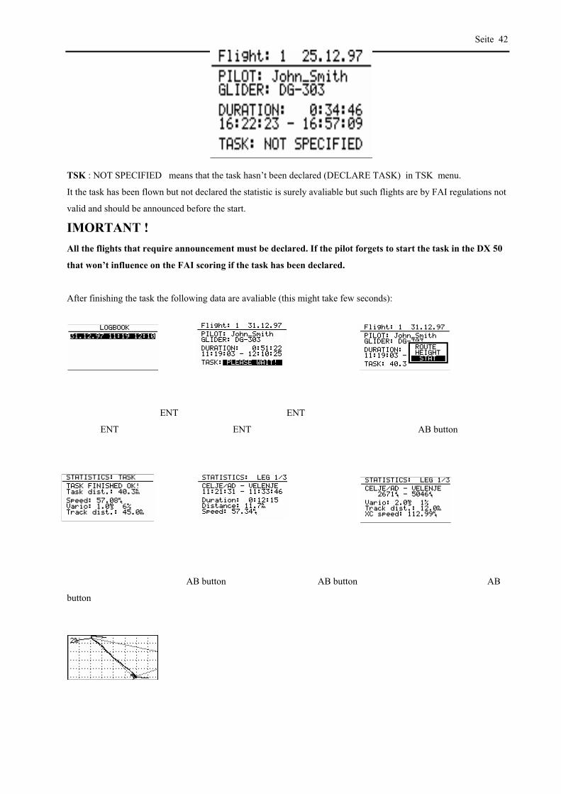
Seite 42
TSK : NOT SPECIFIED means that the task hasn’t been declared (DECLARE TASK) in TSK menu.
It the task has been flown but not declared the statistic is surely avaliable but such flights are by FAI regulations not
valid and should be announced before the start.
IMORTANT !
All the flights that require announcement must be declared. If the pilot forgets to start the task in the DX 50
that won’t influence on the FAI scoring if the task has been declared.
After finishing the task the following data are avaliable (this might take few seconds):
ENT ENT
ENT ENT AB button
AB button AB button AB
button
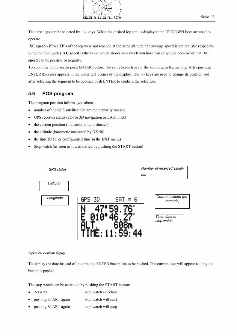
Seite 43
The next legs can be selected by +/- keys. When the desired leg stat. is displayed the UP/DOWN keys are used to
operate.
XC speed - if two TP’s of the leg were not reached at the same altitude, the average speed is not realistic (especial-
ly by the final glide). XC speed is the value which shows how much you have lost or gained because of that. XC
speed can be positive or negative.
To zoom the photo sector push ENTER button. The same holds true for the zooming in leg maping. After pushing
ENTER the cross appears in the lower left corner of the display. The +/- keys are used to change its position and
after selecting the segment to be zoomed push ENTER to confirm the selection.
5.6 POS program
The program position informs you about:
number of the GPS satelites that are momentarily tracked
GPS receiver status (2D- or 3D navigation or LAST FIX)
the current position (indication of coordinates)
the altitude (barometic measured by DX 50)
the time (UTC or configurated time in the INIT menu)
Stop watch (as soon as it was started by pushing the START button)
Figure 20: Positions display
To display the date instead of the time the ENTER button has to be pushed. The current date will appear as long the
button is pushed.
The stop watch can be activated by pushing the START button:
START stop watch selection
pushing START again stop watch will start
pushing START again stop watch will stop
GPS status Number of received satelli-
tes
Latitude
Longitude Current altitude (ba-rometric)
Time, date or stop watch

Seite 44
pushing START again the stop watch will reset
By pushing ENTER button the current time is displayed again.
Attention:
The indication “Last Fix” appears as long as the GPS is not ready for navigation. Meanwhile those coordinates are
indicated which the GPS module has stored last.The current position coordinates are only indicated as long as the
GPS is in the 2D or 3D mode.

Appendix Page
i
6 Appendix
6.1 Cable connection
1921 031 141 251 36
1 471 58
S 1S U B D 1 5
12345
162738495
T X P C
R X P CN F
T E M P . E X T E R N A L
+ 1 2 V D C
G N D
G N D
B i n d e r 5 P0 9 - 0 0 9 7 - 0 0 - 0 5
R S 2 3 2 - P C
S U B D 9 S t e c k e r
S P E A K E R
N M E A
N . C .
S C E x t e r n a l
S p e a k e r
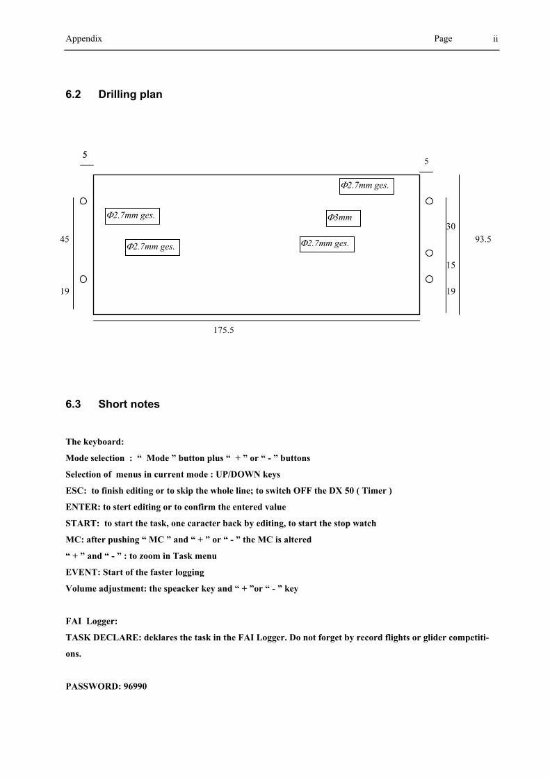
Appendix Page
ii
6.2 Drilling plan
6.3 Short notes
The keyboard:
Mode selection : “ Mode ” button plus “ + ” or “ - ” buttons
Selection of menus in current mode : UP/DOWN keys
ESC: to finish editing or to skip the whole line; to switch OFF the DX 50 ( Timer )
ENTER: to stert editing or to confirm the entered value
START: to start the task, one caracter back by editing, to start the stop watch
MC: after pushing “ MC ” and “ + ” or “ - ” the MC is altered
“ + ” and “ - ” : to zoom in Task menu
EVENT: Start of the faster logging
Volume adjustment: the speacker key and “ + ”or “ - ” key
FAI Logger:
TASK DECLARE: deklares the task in the FAI Logger. Do not forget by record flights or glider competiti-
ons.
PASSWORD: 96990
!2.7mm ges. !2.7mm ges.
!2.7mm ges.
!3mm !2.7mm ges.
175.5
5 5 5
93.5
19
15
30
45
19

®
OPERATING MANUAL FLARM COLLISION WARNING UNIT
Status Software Version 4.04 (June 03, 2008)
This is a translation of the German manual.
© 2003-2008 FLARM Technology GmbH Zurich-Switzerland
www.flarm.com [email protected]

OPERATING MANUAL FLARM COLLISION WARNING UNIT
Version 4.04E Page 2 of 13 June 03, 2008
1. Welcome to the FLARM user community
Thank you for purchasing FLARM, a modern low-cost collision-warning unit for sailplanes and light aircraft. The main task for FLARM is to support the pilot, while he scans the airspace ahead with his own eyes. FLARM is simple to use and does not distract the pilot from the main business in hand.
Sport flying is an activity that is associated with considerable risks for crew, passengers, third parties and other objects. In order to make full and safe use of FLARM, it is absolutely essential to be fully aware of the risks, operating conditions, restrictions and limitations associated with the use of FLARM, ensure a proper installation and do regular software updates. This includes familiarity with and observance of this Operating Manual and the Installation Manual. Additional configuration information can be found in the ‘Data Port Specifications' document, e.g. how to suppress additional data at the serial port what might be required in international championships.
We welcome user feedback and reports, suggestions for improvements, and pictures that will help us make further improvements to FLARM. Feedback reports should give a detailed description of the situation, quoting the Hardware and Software versions used, plus the flight data records in IGC format with short time recording intervals.
The latest version of this handbook and other related documents can be found at the Website www.flarm.com. This Website also has answers to Frequently Asked Questions.
This Website also carries announcements when new software versions or functions become available. If you enter your name on the mailing list, you will automatically receive notification of changes as and when they happen: https://lists.flarm.com/mailman/listinfo/user-list_flarm.com
To use existing devices in April 2008 or later, it is required to update the software to version 4.00 or higher. Use the free PC installation software available at www.flarm.com. You need a PC with Windows 98 / ME / 2000 / XP with a serial port or a suited USB-serial converter plus a data-power cable like the one used for most IGC flight recorders. This cable connects the PC to FLARM and supplies FLARM with power. Ensure you have configured the correct PC COM-port, only use the Power/Data-port on FLARM (not the Extension-port) and know the printed device serial number. After completion of the software update, use the same PC software to load the most recent obstacle file to FLARM; this file is available on www.flarm.com as well. Then use the PC software to configure the flight recording functionality accordingly. In case of questions, contact your FLARM dealer.
Software-Versions 4.x will only remain operational until March 01, 2011. Before this date, you must update the device in order to use it in the air. The update is available in October 2010.
2. How it works
FLARM receives position and movement information from an internal 16 channel GPS receiver with an external antenna. A pressure sensor
1 further enhances the accuracy of position measurements. The
predicted flight path is calculated by FLARM and the information - including a unique identifier - transmitted by radio as low-power digital burst signals at one-second intervals. Provided they are within receiving range, the signals are almost at the same time received by further aircraft also equipped with FLARM. The incoming signal is compared with the flight path predicted by calculation for the second aircraft. At the same time, FLARM compares the predicted flight path with known data on obstacles, including electric power lines, radio masts and cable cars.
If FLARM determines the risk of dangerous proximity to one or more aircraft or obstacles, the unit gives the pilot warning of the greatest danger at that moment. The warning is given by a whistle sound (beep) and bright light emitting diodes (LED). The display also gives indication of the threat level, plus the horizontal and vertical
1 bearing to the threat. During circling flight different methods of calculation are employed to those
used during straight flight.
The GPS and collision information received from other aircraft can also be made available for third party equipment (e.g. external display, speech synthesizer, PDA) via a serial data output. Such equipment is available from a number of manufacturers.
1 Requires Hardware Version 2 or higher. However, the vertical bearing on the serial data output is also available to third-party
equipment on Hardware Version 1.
OPERATING MANUAL FLARM COLLISION WARNING UNIT
Version 4.04E Page 3 of 13 June 03, 2008
The operating range is very dependent upon the antenna installation in the aircraft. The normal range is about 2 km. In individual cases the range may be up to 5 km, which can be valuable for fast sailplanes with a speed of up to 250 kt, providing the pilots in both aircraft with a warning enabling visual identification and reaction to the potential hazard. The effective range can easily be verified with an online tool
2. Warnings are
given in order of the time remaining before a potential collision, not the geometrical distance. The first warning level for another aircraft or an obstacle is delivered when less than 18 seconds remain to the possible collision; the second warning level is delivered when less than 13 seconds remains; the third level when less than 8 seconds remains.
The warnings continue as long as FLARM calculates a threat of collision. The warning level may decline or be cancelled, depending upon the prediction. The warnings are selective; they are only issued if the calculation reveals a high probability of collision in the near future. The alarm sensitivity can be configured with the PC.
In addition, FLARM operates as an IGC-file compatible flight recorder including the G-record. Flight logs can be read out either via the SD-card or via the data port and a suitable cable. The SD card does not need to be carried on during the flight. FLARM is optionally also available as diamond-level IGC-approved Flight Recorder, optionally with Engine Noise Level sensor (ENL).
With the standard April 2008 obstacle databank there is memory for more than 50 hrs of flight recording at a 4s interval. Use the free PC-software to download flights to your PC and to properly configure your device for flight recording. Flight recording automatically starts when the aircraft is moving and ends when the unit is switched off. Switching off the device during the flight for a longer period results in separate flight record files. Allow at least 2 minutes (if the interval is 4s, our recommended value) after landing before you switch off the device else you loose the last part of the flight. Allow more time after landing if the interval is higher. When the memory is full, the oldest data is overwritten. Always download you flight data before you update the obstacle databank or the software.
FLARM applies for the radio communication between the units a proprietary patent- and copyright-protected protocol. It is not public, but FLARM Technology offers a license contract where it is accessible in the form of a compatible core design ready for integration into 3
rd party systems. These systems are officially declared
as FLARM-compatible. Any non-licensed use, dissemination, copying, implementation or reverse engineering of the FLARM radio communication protocol, the FLARM hardware and software or parts of it is forbidden by law and will be prosecuted. FLARM is a registered trademark and can not be used without license.
3. General Advice on Operation
This Manual must be carried on board the aircraft. When permanently installed in an aircraft, the 'AFM Supplement' must also be carried in the aircraft.
In flight the pilot must have direct sight of and immediate access to a switch or circuit breaker that disconnects FLARM from the aircraft electrical power supply, without affecting other essential aircraft systems. This might be necessary if the pilot suspects that FLARM may be interfering with another on-board system, the suspected presence of smoke, the smell of smoke, or flying in a country where the use of FLARM is not permitted.
FLARM must not be operated at night or with night vision systems.
FLARM will not operate without adequate GPS signal strength. Correct antenna installation has a great effect on the transmission/receiving range.
FLARM is not able to measure its own RF-receiver sensitivity. When the pilot detects that other aircraft are received only when very close or not at all and when the RF-antenna’s positioning is clearly not the cause of it, the device must be checked by the manufacturer.
2 www.flarm.com/support/analyze

OPERATING MANUAL FLARM COLLISION WARNING UNIT
Version 4.04E Page 4 of 13 June 03, 2008
Installation and operation must be on the basis of non-interference with and no hazard to the existing suite of other certified equipment necessary for safe flying operation, or installed to comply with official requirements. Installation and operation must comply with official regulations and requirements. It is recommended that the FLARM, GPS and radio antennae are all installed as far away as practicable - but at least 25 cm from -susceptible aircraft systems such as GPS antennae and the magnetic compass.
The unit must be protected from solid particles or liquids, should not be exposed in use to temperatures below –10°C or above +60 °C , or stored at temperatures –20°C or above +70 °C, because this may cause irreparable damage. On the ground, the unit should be protected from exposure to long periods of direct sunlight, because it is likely to be overheated. Also avoid static discharges to the radio antenna.
Details on correct installation will be found in the Installation Manual.
4. Operating Modes
FLARM operates in two modes, Nearest and Collision. The change from one mode to the other is effected by a two-second push on a button followed by a brief visual confirmation from the unit. After the change has been signalled, the current mode selected is not displayed. When switched on, the unit is in Nearest mode.
The warnings given are identical in both modes, and generally relate to an immediate threat to which the pilot should make an immediate and appropriate reaction. The assumption has been made that following a warning it will take up to 12.5 seconds from the time that the other aircraft is seen, until a change in flight path has removed the threat
3.
When operating in the Nearest mode, the unit also reports the presence of other aircraft operating in the vicinity, even though calculations indicate that they do not represent a threat. The information displayed is limited to a configurable radius (default is three kilometres) and a vertical separation of 500 m. When no aircraft was displayed so far but one is received now, this is signalled with a click-sound. Only one single aircraft is indicated, with Hardware Version 3 or later in green. The optical signal is static (no flashing); the threat intensity is not indicated and there is no sound warning. As soon as FLARM detects the risk of a collision it automatically switches to Collision mode, followed by automatic reversion to Nearest. The choice of mode is presented, such that immediately after pressing the key, the display presents a diverging pattern
(Hardware Version 1 and 2: ; version 3: ).
When operating in the Warning mode a red LED lights up only if the calculation predicts a threat. Warnings are always shown by flashing LEDs, the threat level being shown by the number of LEDs illuminated, by the frequency of flashes, and the simultaneous sound signal (beep). Selection of this mode is indicated by a
upwards converging pattern (Hardware Version 1 and 2: ; Version 3: ) immediately after pressing the selector key.
In both modes the pilot can suppress the display and the acoustic warning: after a double push FLARM will suppress all visual and acoustic signals relating to traffic, obstacles or other threats. The act of selecting suppression is followed by a descending tone. A further double-push reinstates the Collision mode at once and is followed by a rising tone. While warnings are suppressed, FLARM nevertheless continues to transmit signals for reception by other aircraft.
3 These times were published in 1983 FAA Advisory Circular 90-48-C and were based on military data. They relate to fast jet pilots with
no on-board warning systems for other traffic and hazards. The assumption was made that only one aircraft takes avoiding action. Of the 12.5 seconds, five seconds were to recognise the threat of collision and four seconds were required to decide upon avoiding action. No information is available as to whether these times are applicable to light aircraft, sailplanes or helicopters, when using a warning system.

OPERATING MANUAL FLARM COLLISION WARNING UNIT
Version 4.04E Page 5 of 13 June 03, 2008
5. Front Panel
The dark grey front panel of Hardware Versions 1 and 2 has a push-button, four green Status-LEDs, ten red collision warning LEDs and four red LEDs for vertical
1 position
indication.
Push-button
4 green LED (Status)
10 red LED (horizontal)
4 red LED (vertical
1)
The front panel of Hardware Version 3 has a
push-button, four green Status-LED, twelve bicolour LED for horizontal and four bicolour LED for vertical position indication. Depending on the threat caused by other aircraft or obstacles the LED show up red or green. Also included is a microSD-reader which can be used for updates, downloads and configurations. microSD cards are not included, but widely available in electronic and mobile phone shops.
Push-button 4 green LED (Status)
12 LED (horizontal) 4 LED (vertical)
all bicolor
microSD reader
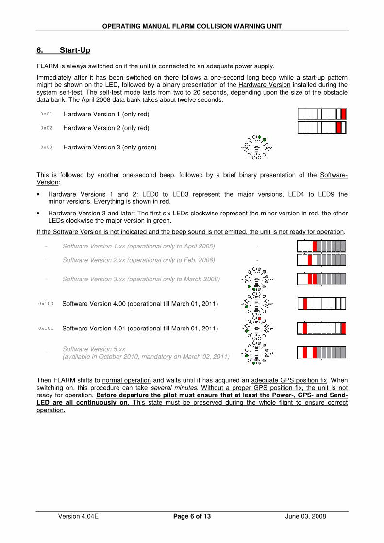
OPERATING MANUAL FLARM COLLISION WARNING UNIT
Version 4.04E Page 6 of 13 June 03, 2008
6. Start-Up
FLARM is always switched on if the unit is connected to an adequate power supply.
Immediately after it has been switched on there follows a one-second long beep while a start-up pattern might be shown on the LED, followed by a binary presentation of the Hardware-Version installed during the system self-test. The self-test mode lasts from two to 20 seconds, depending upon the size of the obstacle data bank. The April 2008 data bank takes about twelve seconds.
0x01 Hardware Version 1 (only red)
0x02 Hardware Version 2 (only red)
0x03 Hardware Version 3 (only green)
This is followed by another one-second beep, followed by a brief binary presentation of the Software-Version:
• Hardware Versions 1 and 2: LED0 to LED3 represent the major versions, LED4 to LED9 the minor versions. Everything is shown in red.
• Hardware Version 3 and later: The first six LEDs clockwise represent the minor version in red, the other LEDs clockwise the major version in green.
If the Software Version is not indicated and the beep sound is not emitted, the unit is not ready for operation.
- Software Version 1.xx (operational only to April 2005) -
- Software Version 2.xx (operational only to Feb. 2006) -
- Software Version 3.xx (operational only to March 2008)
0x100 Software Version 4.00 (operational till March 01, 2011)
0x101 Software Version 4.01 (operational till March 01, 2011)
-
Software Version 5.xx (available in October 2010, mandatory on March 02, 2011)
Then FLARM shifts to normal operation and waits until it has acquired an adequate GPS position fix. When switching on, this procedure can take several minutes. Without a proper GPS position fix, the unit is not ready for operation. Before departure the pilot must ensure that at least the Power-, GPS- and Send-LED are all continuously on. This state must be preserved during the whole flight to ensure correct operation.
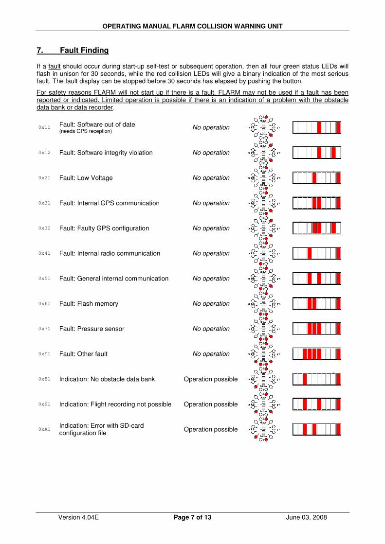
OPERATING MANUAL FLARM COLLISION WARNING UNIT
Version 4.04E Page 7 of 13 June 03, 2008
7. Fault Finding
If a fault should occur during start-up self-test or subsequent operation, then all four green status LEDs will flash in unison for 30 seconds, while the red collision LEDs will give a binary indication of the most serious fault. The fault display can be stopped before 30 seconds has elapsed by pushing the button.
For safety reasons FLARM will not start up if there is a fault. FLARM may not be used if a fault has been reported or indicated. Limited operation is possible if there is an indication of a problem with the obstacle data bank or data recorder.
0x11 Fault: Software out of date (needs GPS reception)
No operation
0x12 Fault: Software integrity violation No operation
0x21 Fault: Low Voltage No operation
0x31 Fault: Internal GPS communication No operation
0x32 Fault: Faulty GPS configuration No operation
0x41 Fault: Internal radio communication No operation
0x51 Fault: General internal communication No operation
0x61 Fault: Flash memory No operation
0x71 Fault: Pressure sensor No operation
0xF1 Fault: Other fault No operation
0x81 Indication: No obstacle data bank Operation possible
0x91 Indication: Flight recording not possible Operation possible
0xA1 Indication: Error with SD-card configuration file
Operation possible
OPERATING MANUAL FLARM COLLISION WARNING UNIT
Version 4.04E Page 8 of 13 June 03, 2008
The communications faults itemised above indicate if internal modules within FLARM are not communicating correctly with each other. For reasons associated with the system, reduced radio range cannot be detected by a single unit alone.
Software-Versions 4.x will only operate until March 01, 2011. Before this date, you must update the device in order to use it in the air. An update with the same functionality can be downloaded free of charge, and will be available in October 2010. Users will be able to load the software with the aid of a suitable power supply/data cable (not supplied). This operation requires the user to have the unit Serial Number to hand. Software validity has to be time-limited to ensure that all FLARM units are mutually compatible and that updates include the latest obstacle data.
8. Status-Display
The green Status Display LEDs operate as follows; normal operating mode is underlined:
• Receive: Lights up when a signal is detected from another aircraft less than the configured range (default is 3 km) away, with a height separation of less than 500 m; otherwise the LED is dark. If the warning is temporarily suppressed (see below) but signals are still received from other aircraft, then the LED flashes.
• Send: Lights constantly during operation and indicates that the on-board FLARM is transmitting. Transmission requires GPS reception.
• GPS: Lights constantly during operation (with very brief interruptions once per second). If the LED is constantly dark and flashes briefly once per second, then there is no GPS reception. When switching on this condition can take several minutes.
• Power: Lights constantly during operation. If the LED flashes, then the power supply has dropped below 8 V. FLARM will not operate below 8 V DC.
The 'Receive' and 'Send' LEDs give no indication of FLARM's transceiver range.
9. Push Button4
The push button can be used to select the following functions:
• Brief Push (<0.8 s) changes the volume from <loud> to <medium> to <quiet> to <silent> (and <loud> again). A short sound is emitted at the new volume selected. The default setting is <loud>.
• Longer Push (2 s) changes mode between <Nearest> and <Collision> when airborne. Visual confirmation. Default setting <Nearest>.
• Longer Push (5 - 8 s, only on the ground) activates the receiver self-test: Two seconds after the button is released, FLARM will show how many other FLARM are received with reduced sensitivity (50% of the normal range). It will then emit a long beep and light one vertical LED for every 10 and a short beep and one horizontal LED for every single received aircraft (e.g. 14 received FLARM is: "beeeeep bep bep bep bep", with one vertical and 4 horizontal LED's). After the self-test, FLARM switches back to normal operations. Note that for other units to be displayed these must be running.
• Double Push suppresses optical and acoustic warnings for five minutes. Suppression is followed by declining melody, normal setting followed by a rising melody. A double push terminates the suppressed operation at once.
• Long Push (>8 s): Re-boot. This procedure is recommended if a fault is apparent. No confirmatory sound signal.
• Very long push (>20 s) brings FLARM back to the factory settings. The very long push deletes all configurations that have been loaded by the user. No confirmatory sound signal.
4 Activate the external display update by pushing the button four times in rapid succession. For details see the Installation Manual.

OPERATING MANUAL FLARM COLLISION WARNING UNIT
Version 4.04E Page 9 of 13 June 03, 2008
10. Aircraft Anti-Collision Warnings
An illuminated red LED indicates the approximate bearing to an aircraft currently posing the biggest threat of collision. The bearing is relative to the track. This indication is inaccurate if there is a strong wind, if the aircraft is in a sideways yaw, or if ground speed is very low (e.g. when a helicopter is in the hover). The display is refreshed every second.
The unit emits an audio warning (beep) tone at the same time as the flashing red optical warning. The time between the warning and possible collision is brief, just a few seconds. Warnings of fixed obstacles are given slightly earlier.
Horizontal bearing indicated on Hardware Versions 1 and 2
Each red LED is allocated to a sector of sky around the aircraft horizontal plane in a side view. The aircraft centreline is indicated by a white line above and below the mid point (between LED4 and LED5). A short white line is located above LED1 and LED8, marking 90° left and right.
• LED 0 ~210° quadrant rear left
• LED 1 270° hard left 9 o'clock
• LED 2 296° left 10 o'clock
• LED 3 321° left 10-11 o'clock
• LED 4 347° front left 11-12 o'clock
• LED 5 13° front right 12-1 o'clock
• LED 6 39° right 1-2 o'clock
• LED 7 64° right 2 o'clock
• LED 8 90° hard right 3 o'clock
• LED 9 ~150° quadrant rear right
Horizontal bearing indicated on Hardware Version 3 and later
The twelve bicolour LED show a compass rose, i.e. the birds view on the traffic situation. ‘Top’ is track-up according the own aircraft. Each LED covers an equal-sized horizontal sector of 30°.
Danger from the front or side
If the threat of collision with another aircraft is from the front or side, but not from the rear, then the threat level will be flagged up by the display. If the threat is moderate (less than 18 seconds to possible collision), a single LED lights up; in the case of a medium threat (less than 13 seconds) then two diodes light up; if the threat is imminent (less than 8 seconds) three LEDs. The threat is at the centre of the illuminated block. The flash and beep frequency increases with the threat.
Moderate threat from ca. 3 o'clock (less than 18 seconds to calculated collision)
Slow flash at 2Hz
Moderate threat from 1 to 2 o'clock (less than 18 seconds)
Slow flash at 2Hz
Medium threat from 1 o'clock (less than 13 seconds)
Medium flash at 4Hz
Immediate threat from 1 to 2 o'clock (less than 8 seconds)
Rapid flash at 6Hz
LED 0 LED 9
LED 8
LED 7
LED 6
LED 5 LED 4
LED 3
LED 2
LED 1

OPERATING MANUAL FLARM COLLISION WARNING UNIT
Version 4.04E Page 10 of 13 June 03, 2008
Danger from the rear
If the threat is from behind, then the threat level on Hardware Version 1 and 2 is given only by the frequency of LED flashes, not the number of LEDs activated.
Danger from the rear, 5 to 7 o'clock Flashing
(H/W Version 3 example shows medium threat from 6 o’clock)
Danger from the rear left, 8 to 7 o'clock Flashing
Danger from the rear right, 4 to 5 o'clock Flashing
Vertical indication
The vertical bearing is indicated by a vertical1
line of four red LEDs and show the bearing relative to a horizontal plane. This is independent of the aircraft’s climb angle. The uppermost or lowest LEDs illuminate when the bearing exceeds 14°. The LED flash frequency is identical and synchronous with that of the horizontal display.
H/W Version 3
H/W Version 2
Traffic indication (only in Nearest-mode)
In Nearest-mode the closest aircraft is shown as long as no warning is necessary. Traffic indications don’t flash, there is no sound and the distance is not shown. Hardware Version 3 and higher show traffic indications in green.
Traffic around 2 o’clock No flashing
Traffic around 7 o’clock No flashing

OPERATING MANUAL FLARM COLLISION WARNING UNIT
Version 4.04E Page 11 of 13 June 03, 2008
11. Obstacle Warnings
The standard obstacle data bank (as of April 2008) has about 33,000 coordinates locating about 11,000 Alpine obstacles
5. This data bank is loaded by FLARM at manufacture; subsequently the user may
upload but not alter up-dated information via a PC. Special data banks, corrections and amendments can be reported to us.
The FLARM display flashes when there is warning of obstacles. The warning always relates to obstacles straight in-line with the current flight heading. In other words there is no horizontal or vertical bearing given to the obstacle. The threat level depends upon the time remaining to impact; the flash and beep frequency increases with reducing distance from the obstacle. The display is refreshed every second.
A warning is given if an aircraft flies under a cable or power line.
An acoustic warning (beep) is given at the same time as the flashing fixed obstacle warning. The time between warning and possible collision is brief, just a few seconds. However, warnings are given of fixed obstacles earlier than those for other aircraft.
Hardware Versions 1 and 2 show obstacles as follows:
Moderate threat (less than 18 seconds to calculated collision) Slow flash 2Hz
Medium threat (less than 13 seconds) Medium flash 4Hz
Immediate threat (less than 8 seconds) Rapid flash 6Hz Hardware Versions 3 and later show obstacles as follows:
A toggling pair of two LED’s is shown, with the toggle frequency depending on the threat.
5 For details on the data sources and status, consult the ‚Obstacle Data Format Specifications’ manual.
Neither FLARM Technology nor these organisations accept any responsibility for the accuracy, completeness or up-to-date status of the data or any direct or indirect damage resulting from using such data. Official data sources only collect data which have been reported by those who own, construct or operate constructions which represent an obstacle, and do not check these reports.
OPERATING MANUAL FLARM COLLISION WARNING UNIT
Version 4.04E Page 12 of 13 June 03, 2008
12. Operating Limitations
FLARM is designed and built as a non-essential 'situation awareness only' unit to only support the pilot, and cannot always provide reliable warnings. In particular, FLARM does not give any guidance on avoiding action. Under no circumstances should a pilot or crewmember adopt different tactics or deviate from the normal principles of safe airmanship. Even with FLARM installed, you remain responsible for flying the aircraft and ensure the safety of passengers and other traffic. The use of FLARM is solely at the discretion of the commander and his delegated crew member. Operation must be preceded by thorough familiarisation by the commander or his delegated crew member with the Operating Manual.
FLARM will only give warnings of other aircraft that are likewise equipped with a compatible unit. FLARM does not communicate with Mode A/C/S transponders and is not detected by ACAS/TCAS/TPAS or Air Traffic Control. Likewise FLARM does not communicate with FIS-B, TIS-B or ADS-B.
Compatible FLARM units must be within range in order to provide a warning. The range is very much determined by the type, installation and position of the radio antennae, plus the relative positions of the two aircraft. Under optimum conditions the internal antennae can give a head-on range of up to 5 km; normally, range is about 2 km, which is adequate for light aircraft and sailplanes. The radio signals can only be received by line of sight. There is no FLARM signal between two aircraft on opposite sides of the same mountain.
FLARM has to know its current position in order to operate. For this reason, FLARM will only operate in the presence of good quality three-dimensional GPS reception. GPS reception is greatly influenced by the installation and position of the antenna, and aircraft attitude. This is particularly true during turns, when flying close to mountain slopes and in areas known for poor reception. If the installation is poor the GPS signal quality may be reduced. In particular, there can be rapid degradation of height calculations. FLARM resumes operation as soon as the GPS reception quality is adequate.
Movements calculated by the GPS relate to a fixed system of terrestrial coordinates. In strong wind there may be a substantial difference between aircraft heading and track, leading to a distortion of the threat bearing. If the wind speed is one third of True Airspeed (TAS) and the yaw-free aircraft Heading is 90° out of wind, then the threat indication displayed has an error of about 18°. If the wind is very strong, the Track can deviate up to 180° from Heading. Under such circumstances and when circling, the calculation and warnings given are unusable.
When close up, when two aircraft are at the same or similar height, or GPS reception is poor, the vertical bearing indication is imprecise and fluctuates.
FLARM calculates the predicted flight path of the aircraft to which it is fitted for less than the next 20 seconds. This prediction is based on immediate past data, current position- and movement data, plus a movement prediction model that is optimised for the respective user. This forecast is associated with a number of uncertainties that increase with an extension of the forecast time. There is no guarantee that an aircraft will actually follow the predicted flight path. For this reason, the warning issued will not be accurate in all cases. In sport flying flight path predictions of more than 30 seconds are unusable. This is particularly true for sailplanes and hang gliders. For this reason, the radio range is generally adequate.
Warnings are given at very short notice, i.e. the warning is given within a time frame of from a few seconds to 18 seconds, depending upon the closest predicted proximity, as calculated. The threat intensity (pitch of the warning tone, LED block width, flash interval) flags up the threat (collision time point), but not the geometric distance. FLARM only issues a warning if the calculation forecasts a considerable threat. For this reason, it is usual - depending upon the mode selected - that no warning is given about the presence of other aircraft, in spite of the fact that signals have been correctly received.
When a number of moving threats or fixed objects are within range, then FLARM gives warning only of the most dangerous in accordance with the threat calculation algorithm. The pilot is unable to confirm receipt of this warning, nor is he able to call for presentation of further threats. In spite of the warning issued for one other aircraft or fixed objects, it is quite possible that there are several further aircraft or fixed objects that represent a greater threat than that which has been signalled. When the unit simultaneously detects a threat from moving and fixed obstacles, then the warning issued relates to the earliest likely collision.

OPERATING MANUAL FLARM COLLISION WARNING UNIT
Version 4.04E Page 13 of 13 June 03, 2008
FLARM indicates the rough position of the aircraft or obstacle that currently represents the biggest threat, in accordance with the algorithmic calculation; FLARM Hardware Version 2 (and onwards) also displays a vertical bearing. In the case of fixed obstacles, the unit does not signal a bearing. FLARM does not indicate where the closest proximity may occur, nor does it signal avoiding action. Whether and how avoiding action is taken is solely a matter for the pilot, who must base his decision on his own observation of the airspace. In taking his decision, he must comply with the Rules of The Air and ensure that no additional hazard is caused by his action. Depending upon the phase of the flight, FLARM uses different forecasting methods, movement models and warning calculations, to provide the pilot with the best possible support without causing a distraction. For example, when a sailplane is circling, the system sensitivity is reduced. These models and processes are optimised, but are nevertheless a compromise. As seen by the pilot these models are the source of 'false alarms'; i.e. FLARM would give warnings of 'threats' that would not subjectively be regarded as a real danger. It is quite possible that FLARM will not give warning of the highest threat, or will give any warning at all.
Obstacle warnings (e.g. cables, antenna masts, cable cars, avalanche dynamite wires, power lines) are dependent on the information having been stored correctly in the internal data bank. The unit cannot give warning of any fixed object that has either been incorrectly stored, or not stored at all. No data bank is complete, up-to-date and correct. Obstacle information stored has usually been simplified; for example, FLARM assumes that a power wire is slung absolutely straight between two fixed points with no sag. Likewise, data for power lines and cable cars does not include all intermediate masts. In addition, FLARM data does not include terrain data and no such warnings are possible.
FLARM radio communications take place in a license-free band in which there is general freedom to transmit and receive. This means that the band is also available to a number of other uncoordinated users. FLARM has no exclusive right to the use of this band and there is no guarantee that FLARM will not be subject to interference by third parties.
There are national differences in frequency allocation and operating conditions between countries. The aircraft commander and user are solely responsible for ensuring that their use of FLARM conforms with local regulations. No radio licence is required for FLARM in Switzerland, Germany and France.
The radio transmission protocol employed places no limit on the number of units that may be operated within a given range. However, an increasing number of units within range is associated with a reduction in the probability that a single coded signal will be received ('graceful degradation'). The probability is small that subsequent signals will not be received from the same transmitter. FLARM is designed to receive and process signals from up to 50 aircraft within range. A high number of FLARM units within range has no effect on range.
The transmitter has no effect on what the receiver in the other aircraft does with the data. It is possible that this data may be captured and stored by other aircraft, or by ground stations, or used for other purposes. This opens up a range of possibilities, some of which may be in the pilot's own interest, (e.g. automated generation of an sailplane launch logging system, aircraft tracking, last position recovery), while others may not be (e.g. detecting tailing of other aircraft, airspace infringements, failure to take avoiding action prior to a collision). When FLARM makes a transmission, the signal also bears a unique identification code that can trace to the pilot or aircraft registration. The user can - even though this is not recommended - configure the unit so that identification is generated randomly and alters at one-minute intervals, making a back-trace difficult.
Operation of FLARM is limited to non-commercial day VFR flights. FLARM may not be used for navigational purposes or aerobatics.
At present FLARM has not been certified or tested in line with the usual aviation procedures (e.g. DO-160E). The FLARM software development is roughly in-line with Level E of DO-178B; i.e. a partial or total failure of FLARM will have no effect upon the safe operation of the aircraft, nor does it increase crew workload.
Operation of FLARM is forbidden in the USA or Canada or in aircraft registered in the USA or Canada. The association FLARM Technology, FLARM Technology GmbH, its associates, owners, staff, management, development team, suppliers, manufacturers and data suppliers accept no responsibility for any damage or claims that may arise from use of FLARM.

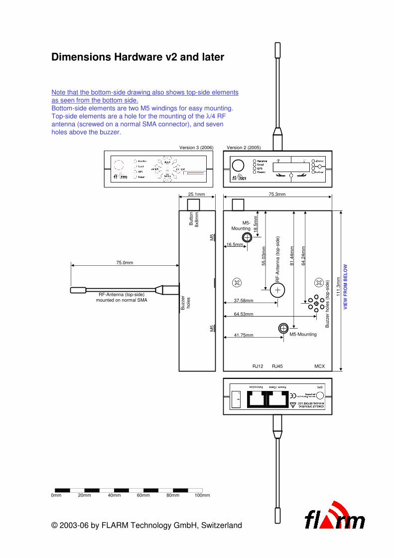
75.3mm
VIE
W F
RO
M B
EL
OW
111
.3m
m
16.5mm
41.75mm
81.4
4m
m
18.5
mm
55.0
3m
m
37.58mm
64.53mm
64.2
4m
m
M5-Mounting
M5-
Mounting
RF
-Ante
nn
a(t
op
-sid
e)
Buzze
rhole
s(t
op
-sid
e)
25.1mm
75.0mm
RF-Antenna (top-side)
mounted on normal SMA
Buzze
r
hole
s
M5
M5
Butto
n
8x8m
m
© 2003-06 by FLARM Technology GmbH, Switzerland
RJ45 MCXRJ12
0mm 20mm 40mm 60mm 80mm 100mm
Note that the bottom-side drawing also shows top-side elements
as seen from the bottom side.
Bottom-side elements are two M5 windings for easy mounting.
Top-side elements are a hole for the mounting of the λ/4 RF
antenna (screwed on a normal SMA connector), and seven
holes above the buzzer.
Dimensions Hardware v2 and later
Version 3 (2006) Version 2 (2005)

75.3mm
VIE
W F
RO
M B
EL
OW
111
.3m
m
16.58mm
41.75mm
81.4
4m
m
16.4
3m
m55.0
3m
m
37.58mm
64.53mm
63.7
3m
m
M5-Mounting
M5-Mounting
RF
-Ante
nn
a(t
op
-sid
e)
Buzze
rhole
s(t
op
-sid
e)
25.1mm
75.0mm
RF-Antenna (top-side)
mounted on normal SMA
Buzze
r
hole
s
M5
M5
Butto
n
8x8m
m
© 2003-06 by FLARM Technology GmbH, Switzerland
Dimensions Hardware v1
(red shows parts shifted between v1 and later versions)
RJ45 MCX
0mm 20mm 40mm 60mm 80mm 100mm
Note that the bottom-side drawing also shows top-side elements
as seen from the bottom side.
Bottom-side elements are two M5 windings for easy mounting.
Top-side elements are a hole for the mounting of the λ/4 RF
antenna (screwed on a normal SMA connector), and seven
holes above the buzzer.

DG200 15m/17m
DG 202
Maintenance Manual
!"#$%&'()%%% *!"#$%&'()%%%%
!+ $&+ , - +


Intentionally Blank


Intentionally Blank


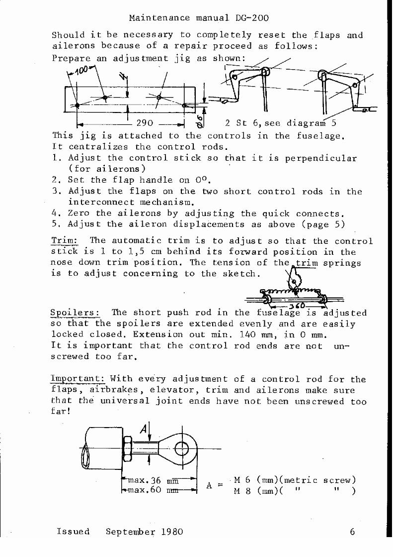
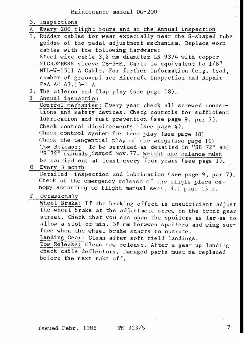


Intentionally Blank


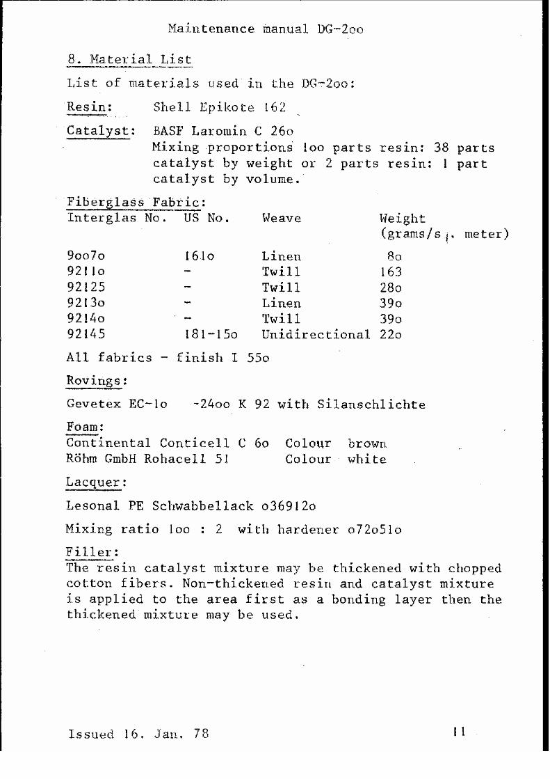

Intentionally Blank


Intentionally Blank


Intentionally Blank
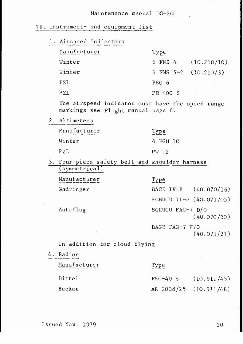
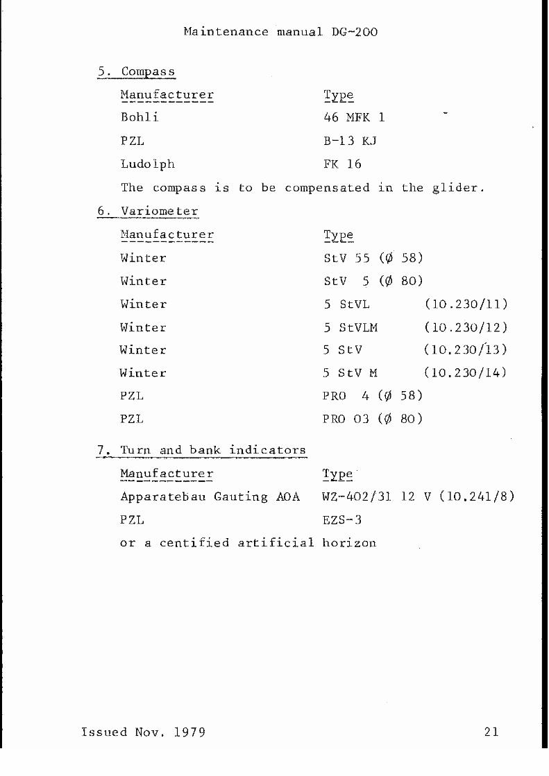

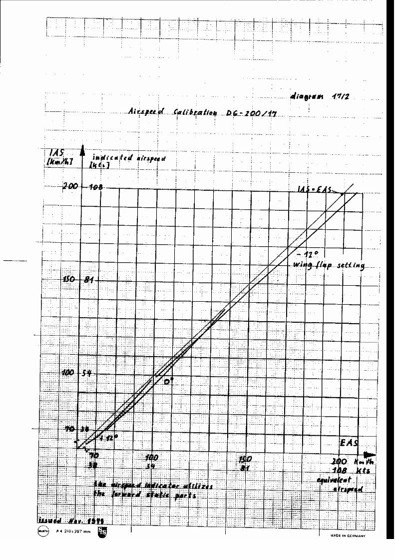
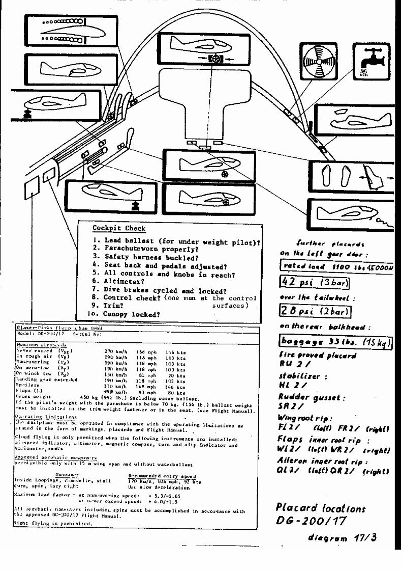


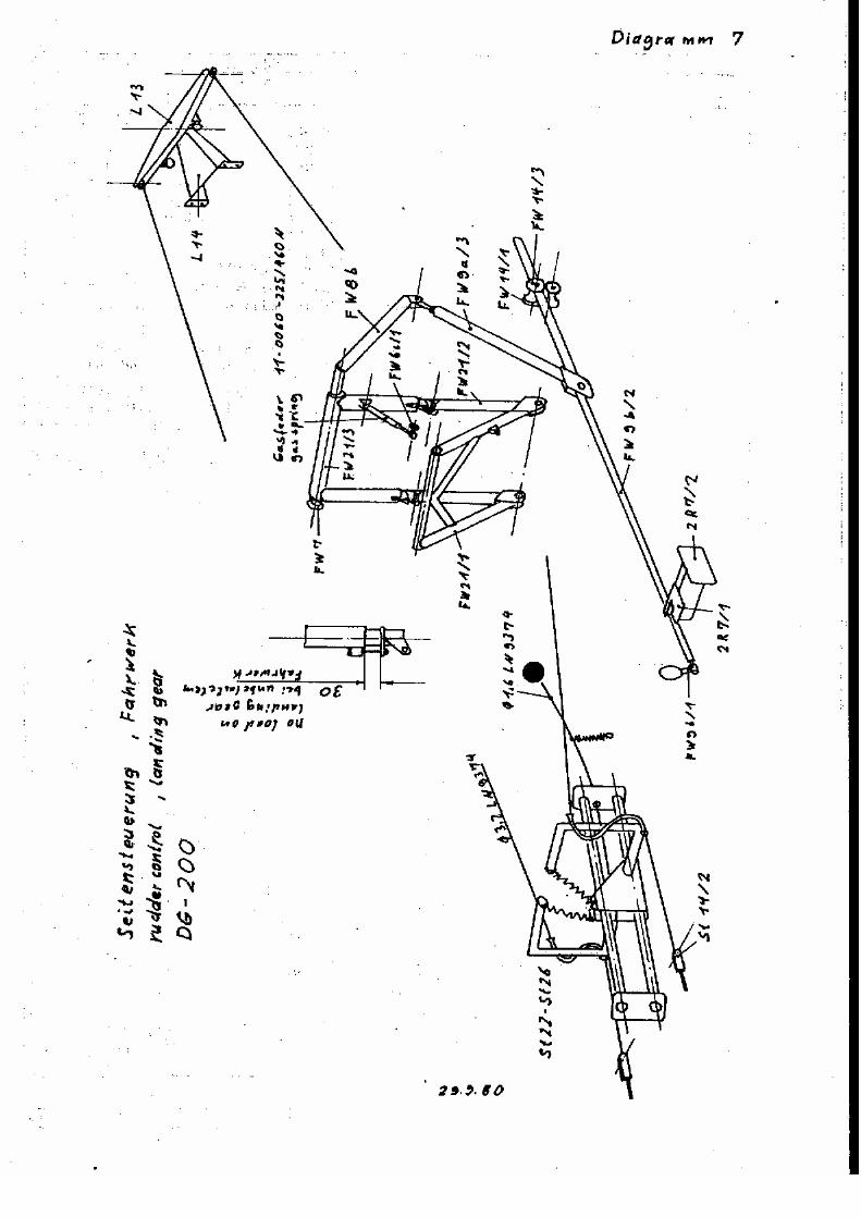


Intentionally Blank