Embed Size (px)
Citation preview
DFS ADS-B Implementation in High Density
Radar Controlled Airspace – Experiences and
Challenges
Stefan Stanzel DFS Deutsche Flugsicherung GmbH, Langen, GERMANY
Abstract
The German Air Navigation Service Provider (ANSP) DFS Deutsche Flugsicherung
(DFS) is operating a surveillance infrastructure mainly based on radars and
multilateration systems, which provides surveillance information and receives aircraft
derived data. The implementation and use of the new surveillance technology Automatic
Dependent Surveillance – Broadcast (ADS-B) has to provide benefits in terms of safety,
performance or costs. DFS operations require a permanent double surveillance coverage
for the area of responsibility. This requirement actually means triple surveillance
coverage (in order to provide a seamless service also in case of system outages or planned
down times). DFS is implementing ADS-B as the third surveillance layer to reduce costs.
Each surveillance layer has to fulfil the performance and safety requirements
independently. The fulfilment of safety requirements, integrity and continuity, will
require validation of the passively received ADS-B information.
Data integrity and continuity need to be considered w.r.t. safety requirements, but
may also have to address security. The integrity of ADS-B data can be ensured either by
comparison with data from other surveillance sensors (dependent validation) or by
analyzing the properties of the data itself (independent validation). The independent
validation of the ADS-B data is a necessary prerequisite for providing a self-contained
independent surveillance layer using the ADS-B technology. In a first step, DFS will
implement ADS-B as a dependent layer: (1) for validation of the assumption on
surveillance performance, (2) to gain experience on data integrity and data continuity, (3)
to prepare possible mitigations e.g. against spoofing or jamming and (4) to recognize
potential shortcomings in the airborne installations and identify possible mitigations. This
first step will support necessary developments (e.g. ADS-B Validation Unit) to move
with ADS-B towards the use as an independent surveillance layer reducing infrastructure
costs and improve radio spectrum protection.
EPiC Series in Computing
Volume 67, 2019, Pages 1–12
Proceedings of the 7th OpenSky Workshop 2019
C. Popper and M. Strohmeier (eds.), OpenSky19 (EPiC Series in Computing, vol. 67), pp. 1–12
1 Legislative Context
The Surveillance Performance and Interoperability Requirements Implementing Rule SPI-IR 1207
was published in 2011 (SPI-IR 1207/2011 (EUROPEAN COMMISSION, 2011)) and amended in 2014
and 2017 is laying down requirements for the performance and the interoperability of air traffic
surveillance for the single European sky. An ANSP ensures seamless operations within the airspace
under its responsibility and at the boundary with adjacent airspaces by applying appropriate minimum
requirements for the separation of aircraft. The performance requirements describes the accuracy,
availability, integrity, continuity and timeliness of the surveillance data. The evaluation of the
performance requirements is part of the surveillance system acceptance. The rules defined in the SPI-
IR 1207/2011 (EUROPEAN COMMISSION, 2011) will serve as the baseline for an operational
implementation of ADS-B application in a radar environment (ADS-B RAD (EUROCAE, ED-161,
Enhanced Air Traffic Services in Radar-Controlled Areas using ADS-B Surveillance (ADS-B RAD),
2009)). Air to Ground interoperability will be insured by “SPI-IR compliant” aircraft to be able to fly
anywhere and receive a surveillance service. Therefore, ANSPs assume that any “SPI-IR compliant”
aircraft provides data suitable for a surveillance service using any foreseen technology (Radar, WAM,
ADS-B). ANSPs may implement any technology that meets the performance requirements, in other
words there is no mandated specific surveillance technology. The Ground to Ground interoperability
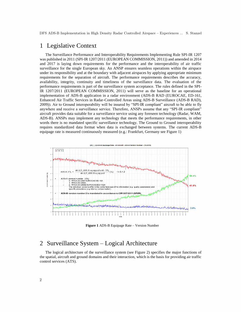
requires standardized data format when data is exchanged between systems. The current ADS-B
equipage rate is measured continuously measured (e.g.: Frankfurt, Germany see Figure 1)
2 Surveillance System – Logical Architecture
The logical architecture of the surveillance system (see Figure 2) specifies the major functions of
the spatial, aircraft and ground domains and their interaction, which is the basis for providing air traffic
control services (ATS).
Figure 1 ADS-B Equipage Rate – Version Number
DFS ADS-B Implementation in High Density Radar Controlled Airspace – Experiences ... S. Stanzel
2

For the spatial domain, it is assumed that the Global Navigation Satellite System (GNSS) is used.
In this context, GNSS is a generic term for the use of existing and future global satellite systems, such
as the US Global Positioning System (GPS), the GLObal NAvigation Satellite System (GLONASS) of
the Russian Federation, Galileo of the European Union and the Chinese Compass.
The minimum surveillance equipment on board of aircraft comprises data sources (ICAO, 2012)
(e.g. for the aircraft identification, 24-bit Mode S address, emergency indicator, flight level and position,
as required; the full set of required data is described in the SPI/IR 1207/2011 (EUROPEAN
COMMISSION, 2011)) and the associated processing and transmission functions by the transponder.
The minimum functional architecture of the ground surveillance domain comprises the following
functions: surveillance sensor, surveillance data distribution, flight data processing and a display system
with is the interface to the air traffic controller (ATCO) (see Figure 3).
Figure 3 Ground surveillance domain
Figure 2 Logical architecture of a surveillance system
DFS ADS-B Implementation in High Density Radar Controlled Airspace – Experiences ... S. Stanzel
3

When assessing the safety/security and performance of the ground domain, all interfaces and
functions must be considered that are relevant from the transmission of data from the aircraft up to the
point where they are displayed at the controller working position. Important aspects are, in particular,
the time between sending and receiving as well as the environmental conditions.
3 ADS-B in RADAR Controlled Airspace
3.1 Objectives
The introduction of the surveillance technology ADS-B in the surveillance system may enhance Air
Traffic Management (ATM) services by improving the overall quality of surveillance (i.e., ADS-B
added to a single independent surveillance layer) such that an operational benefit may include a
reduction in the applied separation standards from that applied in today’s airspace. In some areas where,
for example, single independent surveillance coverage is provided (ADS-B in non-Radar Airspace,
ADS-B NRA), the lack of redundancy induces limited capacity due to the limited surveillance
capabilities (tactical separation) and safety shortcomings. Lack of redundancy may be due to terrain,
cost or physical limitations. Another example – which is more relevant for ANSPs in central Europe -
is where multi-radar presently exists but a radar is to be de-commissioned in the future and the radar
replacement costs are not justified (ADS-B in Radar Airspace, ADS-B RAD).
3.2 Implementation Approach
A common approach from an existing cooperative independent surveillance infrastructure (Mode
A/C/S radar) towards a cooperative dependent surveillance infrastructure (ADS-B) foresees the
introduction of multilateration systems as a significant intermediate step. In addition to their primary
purpose to provide surveillance information based on multilateration techniques, the Wide Area
Multilateration (WAM) systems provide the capability of receiving ADS-B data as well. The ADS-B
data are received from the remote units of the WAM sensor system and relayed to the central target
processor. The target processor filters the ADS-B data in order to suppress duplicates, outdated
information or geographical areas and provides a single ADS-B data stream to the surveillance data
processing system.
Compared to single ADS-B Sensor a WAM system consists of a redundant array of ADS-B
receiving systems, which is designed to improve the reliability of the ADS-B system and the robustness
against disturbances. The WAM build-in verification function of ADS-B against multilateration data
shall ensure that only valid ADS-B data are provided to the surveillance data processing systems.
Additional functions provided by a WAM sensor system are the measurement of ADS-B probability of
detection and coverage range as well as the monitoring of quality indicators.
3.3 DFS ADS-B Implementation Steps
In order to provide ADS-B surveillance data for a certain air traffic control application (e.g. center,
tower) the complete corresponding ground surveillance chain is required to process the ADS-B data.
Therefore, (1) the ADS-B coverage needs to be provided by deployment of ADS-B ground
stations/systems (EUROCAE, ED-129B, Technical Specification for 1090 MHz Extended Squitter
ADS-B Ground System, 2009), (2) the distribution of the ADS-B data is ensured (DFS: SDDS-NG,
ARTE), (3) the surveillance data processing systems (SDPS) are capable of processing ADS-B data
(DFS: ARTAS, PHOENIX) and (4) the ADS-B data are appropriately presented to the ATCO (DFS:
DFS ADS-B Implementation in High Density Radar Controlled Airspace – Experiences ... S. Stanzel
4

ICAS CWP). Usually the needs/capabilities of the Surveillance Data Processing System (SDPS) drive
the requirements of the ground surveillance systems. Currently none of the operational DFS SDPS
systems in use is capable of processing ADS-B data. However, the new DFS SDPS system (ICAS) will
provide ADS-B functionalities. The rollout planning foresees that ICAS will be provided first for the
upper airspace and later on for the lower airspace.
In order to establish the corresponding ADS-B coverage for the SDPS systems a stepwise approach
for the deployment of ADS-B ground systems is planned: (1a) using the ground stations the PAM-FRA
WAM system to provide initial ADS-B coverage for the upper airspace Karlsruhe, (1b) installation of
additional ADS-B ground stations to cover the remaining upper airspace Karlsruhe, (2) additional ADS-
B infrastructure installation to cover the lower airspace in the south of Germany and (3) expansion of
the ADS-B infrastructure to cover the remaining lower airspace (see Figure 4).
The operational use of ADS-B data in the DFS surveillance application requires that (1) only ADS
B MOPS V2 (EUROCAE, ED-102A, Minimum Operational Performance Standards for 1090 MHz
Automatic Dependent Surveillance (Equivalent to RTCA DO-260B) (Equivalent to RTCA DO-260B:
Minimum Operational Performance Standards for 1090 MHz Automatic Dependent Surveillance),
2009) data are used (according to CIR (EU) 1207/2011, (2) target tracks are not established by ADS B
only (until independent validation is implemented) and (3) a validation function needs to be established.
The ADS-B data used for operational surveillance are filtered according quality parameters (see Figure
5).
The DFS design of the ADS-B infrastructure foresees that advanced, high performance Ground
Stations will be used. These ADS-B Ground Stations will consist of multichannel receivers with
sectorized antennas. In order to achieve an optimized coverage fulfilling high performance requirements
(short Update Period (UP) using ADS-B data driven mode and high Probability of Update (PoU) even
in environments with demanding radio field load). The goal is reduce life tine costs, which are mainly
depending on site-specific costs (communication costs, rental charges, maintenance costs, etc.).
Figure 4 DFS ADS-B Implementation Steps
DFS ADS-B Implementation in High Density Radar Controlled Airspace – Experiences ... S. Stanzel
5

Therefore, the reduction of the number of necessary sites in order to provide a ADS-B operational
coverage is key for the economical introduction of this surveillance technology.
4 ADS-B Performance Assessment (APA)
The following performance metrics analyzed by DFS at surveillance sensor and surveillance data
processing system (tracker) level using international evaluation standards (EUROCONTROL, 2012)
(EASA, 2013) (Stanzel, 2009) are (see Figure 6):
Probability of Update (at a defined Update Period)
The PoU is the rate of the number of received position updates and the number of expected
position updates. The PoU is determined per target and addition per defined volume of
airspace and as an overall value.
Horizontal Position Root-Mean-Square Error The error on the provided horizontal position is the 2D Euclidian distance between the
horizontal position provided by the surveillance system under test and the reference
horizontal position of the corresponding aircraft at the time when the updated position was
output/delivered. This error takes into account any uncompensated latency between the
time of applicability of the provided horizontal position and the time when the horizontal
position was delivered to another system.
Ground Speed Root-Mean-Square Error The calculation of the reference aircraft velocity and angle will follow the same principle
as for horizontal position error, i.e. the provided value will be compared with the reference
value at the time the target report including track velocity data item was output.
Figure 5 DFS ADS-B Implementation – Phase 1A
DFS ADS-B Implementation in High Density Radar Controlled Airspace – Experiences ... S. Stanzel
6

The comparative surveillance sensor performance assessment indicated that the horizontal position
error and aircraft velocity/angle error is significantly improved by use of ADS-B data. Further
performance parameter, which were analyzed: e.g. data transmission delay, track initiation delay,
update period, probability of update and probability of sustained misses.
The SDPS in the DFS surveillance infrastructure use multi sensor/radar tracking systems
(PHOENIX (DFS), ARTAS (EUROCONTROL)), which correlate and fuse the surveillance
information from various sensors. The quality of surveillance data provided by conventional sensors
(radar and multilateration) is already remarkable high. The existing surveillance systems providing
redundant and seamless coverage. Therefore, the surveillance data processing system receive already
high performance surveillance data, which allows a very precise tracking of targets. The introduction
of an ADS-B sensor will further improve the tracking quality (see Figure 7).
Figure 7 ADS-B Track Performance Assessment
Figure 6 Sensor Performance Assessment
DFS ADS-B Implementation in High Density Radar Controlled Airspace – Experiences ... S. Stanzel
7

5 ADS-B Safety Assessment (ASA)
The ADS-B Safety Assessment conducted by DFS consisted of four Technical Workshops
(technicians) and three Operational Workshops (ATCOs). The evaluated topics are follows: data
quality, data rate, aircraft identification, security (e.g.: jamming, spoofing), identification for ADS-B
unconfirmed Tracks and operational presentation of ADS-B information. The ADS-B security
assessment was carried out during several national (LuFo: TeFiS) and international (SESAR 14.4.3)
research projects (Dr. Heidelmeyer & Dr. Hoffmann, 2008) (see Figure 8).
6 ADS-B Validation Unit (AVU)
With the surveillance technology ADS-B, the data is generated according to the principle of own-
detection. This means that all data is determined by the respective object (aircraft, vehicle) itself, in
particular its own position. The surveillance sensors used so far by air traffic control (radars, MLAT)
work according to the principle of external external-detection according to which the position of the
respective object is determined by a ground-based sensor. The quality of the position determination
depends on the respective sensor. With external-detection, the performance parameters of the ground-
based sensors are known and continuously monitored. With own-detection, the quality of the position
determination depends on the respective on-board sensor of the target and is therefore no longer the
responsibility of air traffic control. The ADS-B validation unit should guarantee the content integrity
of the ADS-B data (positional data (horizontal position, barometric altitude) and non- positional data
(ACID, flight status, etc.) with suitable methods.
The integrity of ADS-B data can be ensured either by comparison with data from other surveillance
sensors (dependent validation) or by analyzing the properties of the data itself (independent validation),
e.g. by means of simplified TDOA mechanisms. The independent validation of the ADS-B data appears
to be a necessary prerequisite for providing a full Mode S Surveillance Layer based on ADS-B
technology. In this context, the "ADS-B implementation concept at DFS" (V1.0, 2016) already provides
for an ADS-B server in two possible forms (centralized, decentralized) for DFS's ADS-B architecture.
Because of the examination of the architecture variants, a centralized "ADS-B Validation Unit" has
now been identified as the most appropriate system design for the ADS-B server functionality.
Figure 8 ADS-B Security Assessment
DFS ADS-B Implementation in High Density Radar Controlled Airspace – Experiences ... S. Stanzel
8

The ADS-B Validation Unit (AVU) consists of the actual Validation Module and further support
modules (Input/Output, Reporting, Statistic and Control & Monitoring). The Validation Module
performs both dependent and independent validation of ADS-B data (see Figure 9).
The module can be controlled by external Black/White (B/W) lists and has functions to generate
B/W lists automatically. The AVU also filters the data (geographical, quality parameters, ADS-B
version, etc.) for the respective ADS-B services. The support modules of the AVU monitor their
functions, provide information about the status of the ADS-B population (transponder deviation sheets
may be generated) and generate the ADS-B data services.
7 Experiences and Challenges
Examples of the experiences gained during the ADS-B implementation are provided (list not
exhaustive):
7.1 Uncompensated Latency (mainly ADS-B MOPS version 0 und 1)
In the ADS-B airborne system the GPS device receives signals from GPS satellites and determine
the position of the aircraft including the time of applicability. The GPS position is relayed to the
transponder either directly or via the flight management system. The uncompensated latency (UL) is
Figure 9 AVU functional overview
Figure 10 Along Track Deviation caused by UL
DFS ADS-B Implementation in High Density Radar Controlled Airspace – Experiences ... S. Stanzel
9
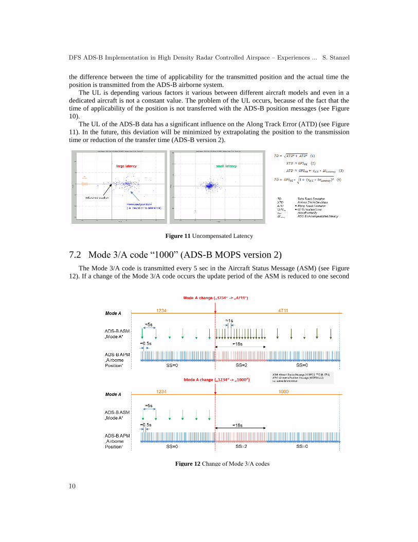
the difference between the time of applicability for the transmitted position and the actual time the
position is transmitted from the ADS-B airborne system.
The UL is depending various factors it various between different aircraft models and even in a
dedicated aircraft is not a constant value. The problem of the UL occurs, because of the fact that the
time of applicability of the position is not transferred with the ADS-B position messages (see Figure
10).
The UL of the ADS-B data has a significant influence on the Along Track Error (ATD) (see Figure
11). In the future, this deviation will be minimized by extrapolating the position to the transmission
time or reduction of the transfer time (ADS-B version 2).
7.2 Mode 3/A code “1000” (ADS-B MOPS version 2)
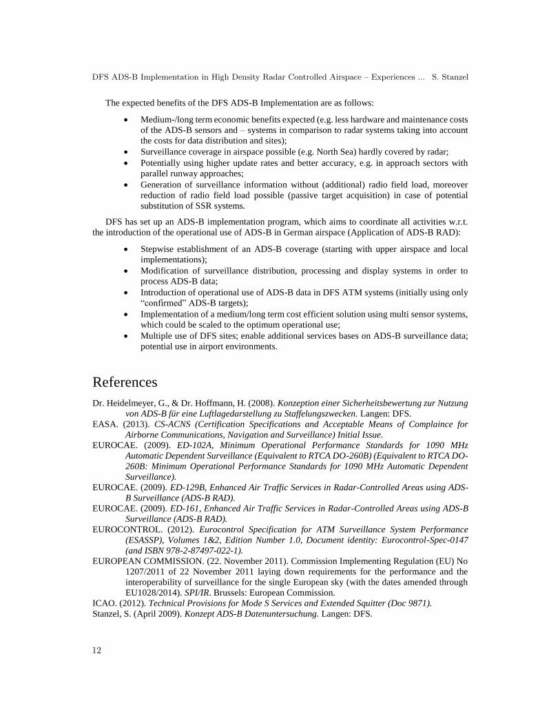
The Mode 3/A code is transmitted every 5 sec in the Aircraft Status Message (ASM) (see Figure
12). If a change of the Mode 3/A code occurs the update period of the ASM is reduced to one second
Figure 11 Uncompensated Latency
Figure 12 Change of Mode 3/A codes
DFS ADS-B Implementation in High Density Radar Controlled Airspace – Experiences ... S. Stanzel
10

for a duration of 18 sec. In addition, the Surveillance Status (SS) flag is set to 2 (temporary alert). These
allows the receiving systems to detect the Mode 3/A change quite fast.
In case of a Mode 3/A code of “1000” no ASM is transferred during ADS-B version 2 transmissions.
The reason for this is to reduce the frequency load.
Because of the ADS-B version 2 is the mandated is the US and Europe, the missing ADS-B Mode
3/A “1000” code needs to be taken into account during the processing of the SDPS in order to prevent
differing information. It has to be noted that the missing Mode 3/A code “1000” could not be derived
from radar replies of the same target. Because only information contained in the Mode S ES messages
are allowed to be used in the ADS-B reports created by the ground sensor. The missing Mode 3/A code
may be supplemented in the SDPS.
7.3 Transient Mode 3A codes
If pilots do not deactivate the transmission of the new Mode 3/A code until the code change has
been completed, Mode 3/A codes (transient), which have been set in the meantime will be transmitted
(see Figure 13).
The Mode 3/A code is used in SDPS as a mean of correlation between surveillance and flight plan
data. If the Mode 3/A code is not correct (e.g. due to transient codes) a wrong or loss of correlation
could be observed. Every fifth Mode 3/A change contain transient Mode 3/A codes. In the investigated
area (see above PAM-FRA P1A), Mode 3/A changes occur rather rarely. It can be assumed that in other
areas the absolute number of Mode 3/A changes can be significantly higher. It is also expected that at
low altitudes the relative amount of transient Mode 3/A codes will increase. SDPS systems have to
adjust to the occurrence of transient codes when processing data from sensors with higher update rates.
In order to cope with the transient Mode 3/A a hysteresis of 2 sec before a new Mode 3/A code is
accepted is applied in SDPS.
8 Conclusion
The objectives are DFS ADS-B Implementation are as follows:
Establishment of a third Mode S Surveillance Layer using ADS-B technology;
The existing surveillance infrastructure (radar and multilateration) enables 3 NM
separation. The design goal is to use ADS-B as part of this multi sensor surveillance
infrastructure;
The existing safety and security level is at least to be maintained;
The performance requirements (e.g. availability, accuracy and integrity) concerning the
ADS-B system are at least as good as SSR (Mode-S radar) systems.
Figure 13 Transient Mode 3A codes (description)
DFS ADS-B Implementation in High Density Radar Controlled Airspace – Experiences ... S. Stanzel
11
The expected benefits of the DFS ADS-B Implementation are as follows:
Medium-/long term economic benefits expected (e.g. less hardware and maintenance costs
of the ADS-B sensors and – systems in comparison to radar systems taking into account
the costs for data distribution and sites);
Surveillance coverage in airspace possible (e.g. North Sea) hardly covered by radar;
Potentially using higher update rates and better accuracy, e.g. in approach sectors with
parallel runway approaches;
Generation of surveillance information without (additional) radio field load, moreover
reduction of radio field load possible (passive target acquisition) in case of potential
substitution of SSR systems.
DFS has set up an ADS-B implementation program, which aims to coordinate all activities w.r.t.
the introduction of the operational use of ADS-B in German airspace (Application of ADS-B RAD):
Stepwise establishment of an ADS-B coverage (starting with upper airspace and local
implementations);
Modification of surveillance distribution, processing and display systems in order to
process ADS-B data;
Introduction of operational use of ADS-B data in DFS ATM systems (initially using only
“confirmed” ADS-B targets);
Implementation of a medium/long term cost efficient solution using multi sensor systems,
which could be scaled to the optimum operational use;
Multiple use of DFS sites; enable additional services bases on ADS-B surveillance data;
potential use in airport environments.
References
Dr. Heidelmeyer, G., & Dr. Hoffmann, H. (2008). Konzeption einer Sicherheitsbewertung zur Nutzung
von ADS-B für eine Luftlagedarstellung zu Staffelungszwecken. Langen: DFS. EASA. (2013). CS-ACNS (Certification Specifications and Acceptable Means of Complaince for
Airborne Communications, Navigation and Surveillance) Initial Issue.
EUROCAE. (2009). ED-102A, Minimum Operational Performance Standards for 1090 MHz
Automatic Dependent Surveillance (Equivalent to RTCA DO-260B) (Equivalent to RTCA DO-
260B: Minimum Operational Performance Standards for 1090 MHz Automatic Dependent
Surveillance).
EUROCAE. (2009). ED-129B, Enhanced Air Traffic Services in Radar-Controlled Areas using ADS-
B Surveillance (ADS-B RAD).
EUROCAE. (2009). ED-161, Enhanced Air Traffic Services in Radar-Controlled Areas using ADS-B
Surveillance (ADS-B RAD).
EUROCONTROL. (2012). Eurocontrol Specification for ATM Surveillance System Performance
(ESASSP), Volumes 1&2, Edition Number 1.0, Document identity: Eurocontrol-Spec-0147
(and ISBN 978-2-87497-022-1).
EUROPEAN COMMISSION. (22. November 2011). Commission Implementing Regulation (EU) No
1207/2011 of 22 November 2011 laying down requirements for the performance and the
interoperability of surveillance for the single European sky (with the dates amended through
EU1028/2014). SPI/IR. Brussels: European Commission.
ICAO. (2012). Technical Provisions for Mode S Services and Extended Squitter (Doc 9871).
Stanzel, S. (April 2009). Konzept ADS-B Datenuntersuchung. Langen: DFS.
DFS ADS-B Implementation in High Density Radar Controlled Airspace – Experiences ... S. Stanzel
12