Embed Size (px)
Citation preview
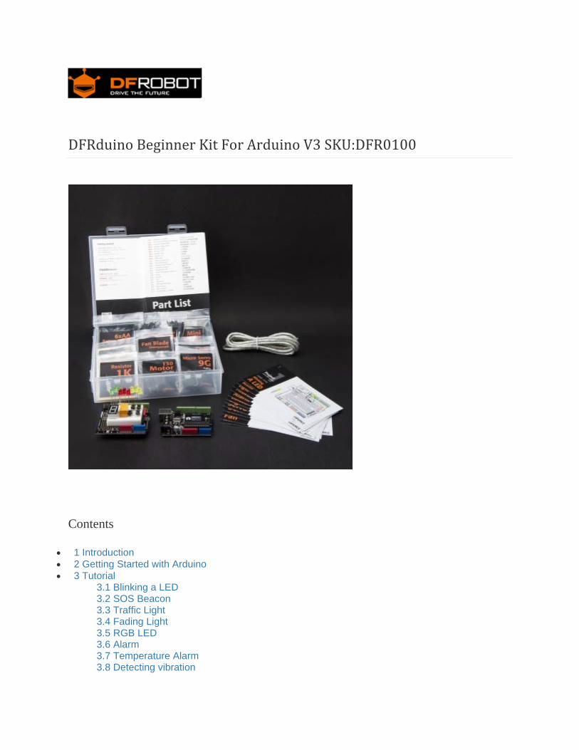
DFRduinoBeginnerKitForArduinoV3SKU:DFR0100
Contents
1 Introduction 2 Getting Started with Arduino 3 Tutorial
3.1 Blinking a LED 3.2 SOS Beacon 3.3 Traffic Light 3.4 Fading Light 3.5 RGB LED 3.6 Alarm 3.7 Temperature Alarm 3.8 Detecting vibration
3.9 Ambient Light controlled LED 3.10 Moving a Servo 3.11 Interact with Servo 3.12 RGB Light Dimmer 3.13 Motor Fan 3.14 Infrared controlled Light 3.15 Infrared controlled LED Matrix
4 FAQ
Introduction Welcome to the electronic interaction world! DFRobot proudly presents the Arduino beginner kit for those who are interested in learning about Arduino. Starting from basic LED control to more advanced IR remote control, this kit will guide you through the world of microcontrollers and physical computing.
A DFRduino UNO R3 (Compatible with Arduino Uno), the most stable and commonly used Arduino processor, together with DFRobot's best selling prototype shield are included in this kit.
GettingStartedwithArduino Introduction: What Arduino is and why you'd want to use it.
Installation: Step-by-step instructions for setting up the Arduino software and connecting it to an Arduino Uno.
Windows Mac OS X Environment: Description of the Arduino development environment and how to change the default language. Libraries: Using and installing Arduino libraries.
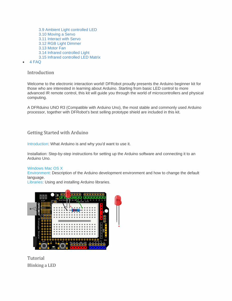
Tutorial BlinkingaLED
/*
# Description:
# Turns on an LED on for one second, then off for one second, repeatedly.
*/
int ledPin = 10;
void setup() {
pinMode(ledPin, OUTPUT);
}
void loop() {
digitalWrite(ledPin,HIGH);
delay(1000);
digitalWrite(ledPin,LOW);
delay(1000);
}
SOSBeacon
The connection diagram is the same with Blinknig a LED tutorial.
/*
# Description:
# Send SOS Beacon by led
*/
int ledPin = 10;
void setup() {
pinMode(ledPin, OUTPUT);
}
void loop() {
// S(...) three dot
for(int x=0;x<3;x++){
digitalWrite(ledPin,HIGH);
delay(150);
digitalWrite(ledPin,LOW);
delay(100);
}
delay(100);
// O(---) three dash
for(int x=0;x<3;x++){
digitalWrite(ledPin,HIGH);
delay(400);
digitalWrite(ledPin,LOW);
delay(100);
}
delay(100);
//S(...) three dot
for(int x=0;x<3;x++){
digitalWrite(ledPin,HIGH);
delay(150);
digitalWrite(ledPin,LOW);
delay(100);
}
delay(5000);
}
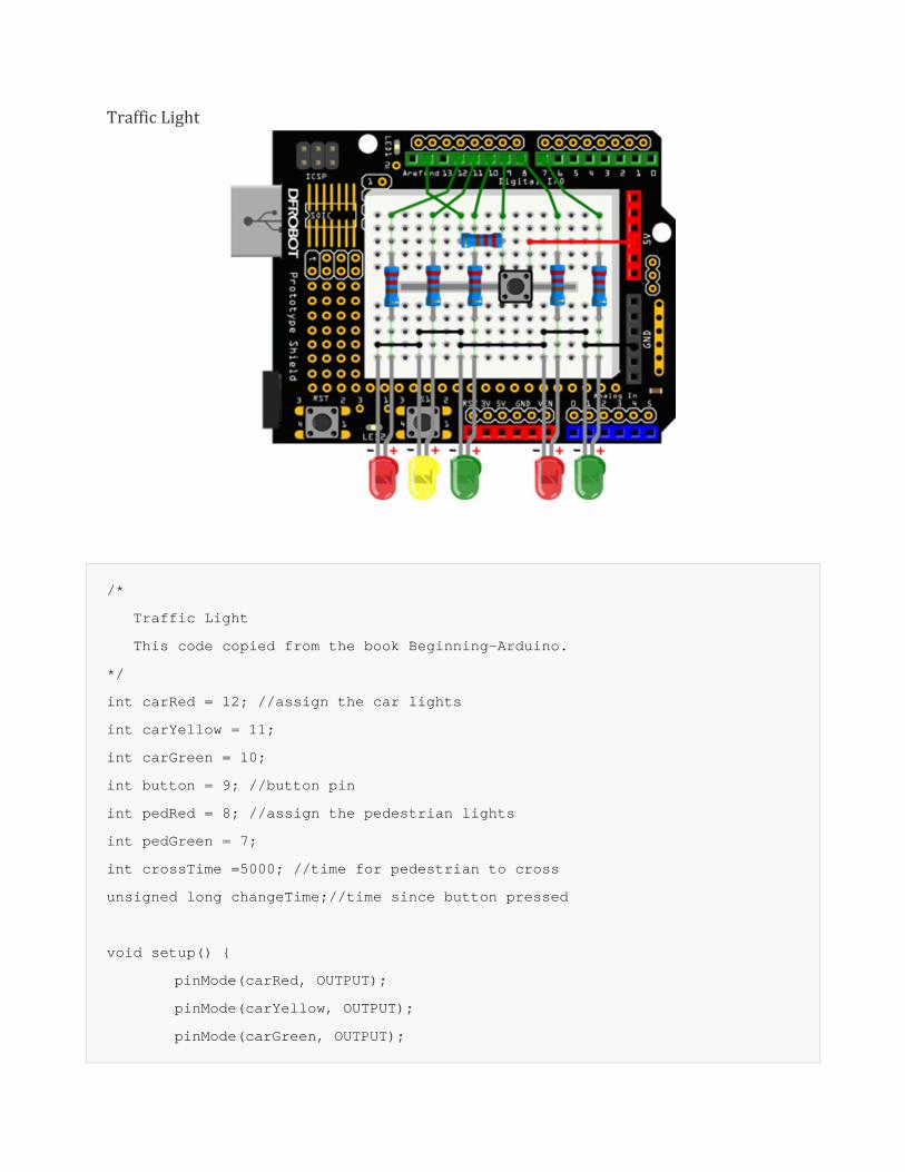
TrafficLight
/*
Traffic Light
This code copied from the book Beginning-Arduino.
*/
int carRed = 12; //assign the car lights
int carYellow = 11;
int carGreen = 10;
int button = 9; //button pin
int pedRed = 8; //assign the pedestrian lights
int pedGreen = 7;
int crossTime =5000; //time for pedestrian to cross
unsigned long changeTime;//time since button pressed
void setup() {
pinMode(carRed, OUTPUT);
pinMode(carYellow, OUTPUT);
pinMode(carGreen, OUTPUT);
pinMode(pedRed, OUTPUT);
pinMode(pedGreen, OUTPUT);
pinMode(button, INPUT);
digitalWrite(carGreen, HIGH); //turn on the green lights
digitalWrite(pedRed, HIGH);
}
void loop() {
int state = digitalRead(button);
//check if button is pressed and it is over 5 seconds since last button press
if(state == HIGH && (millis() - changeTime)> 5000){
//call the function to change the lights
changeLights();
}
}
void changeLights() {
digitalWrite(carGreen, LOW); //green off
digitalWrite(carYellow, HIGH); //yellow on
delay(2000); //wait 2 seconds
digitalWrite(carYellow, LOW); //yellow off
digitalWrite(carRed, HIGH); //red on
delay(1000); //wait 1 second till its safe
digitalWrite(pedRed, LOW); //ped red off
digitalWrite(pedGreen, HIGH); //ped green on
delay(crossTime); //wait for preset time period
//flash the ped green
for (int x=0; x<10; x++) {
digitalWrite(pedGreen, HIGH);
delay(250);
digitalWrite(pedGreen, LOW);
delay(250);
}
digitalWrite(pedRed, HIGH);//turn ped red on
delay(500);
digitalWrite(carRed, LOW); //red off
digitalWrite(carYellow, HIGH); //yellow on
delay(1000);
digitalWrite(carYellow, LOW); //yellow off
digitalWrite(carGreen, HIGH);
changeTime = millis(); //record the time since last change of lights
//then return to the main program loop
}
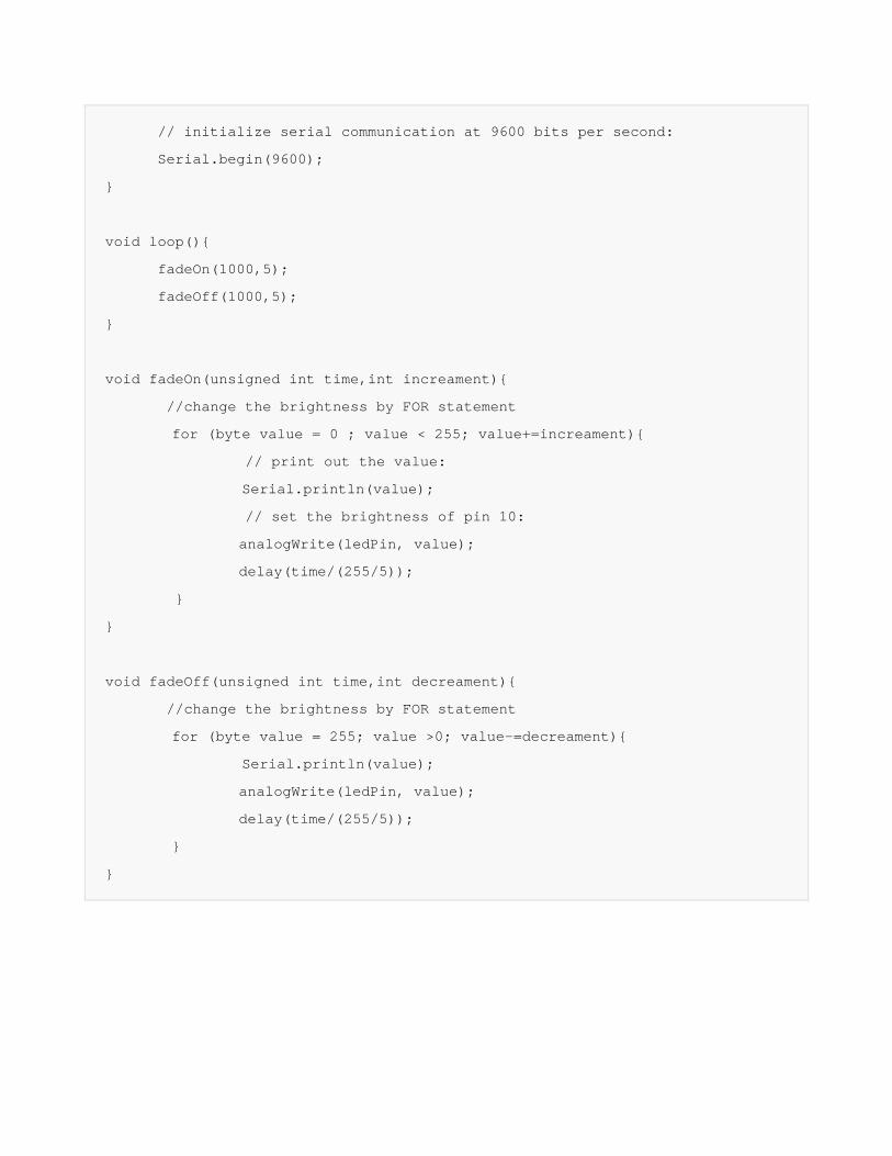
FadingLight
The connection diagram is the same with Blinknig a LED tutorial.
/*
Fading Light
This example shows how to fade an LED on pin 10 using the analogWrite() function.
*/
int ledPin = 10; // the pin that the LED is attached to
void setup() {
// declare pin 9 to be an output:
pinMode(ledPin,OUTPUT);
// initialize serial communication at 9600 bits per second:
Serial.begin(9600);
}
void loop(){
fadeOn(1000,5);
fadeOff(1000,5);
}
void fadeOn(unsigned int time,int increament){
//change the brightness by FOR statement
for (byte value = 0 ; value < 255; value+=increament){
// print out the value:
Serial.println(value);
// set the brightness of pin 10:
analogWrite(ledPin, value);
delay(time/(255/5));
}
}
void fadeOff(unsigned int time,int decreament){
//change the brightness by FOR statement
for (byte value = 255; value >0; value-=decreament){
Serial.println(value);
analogWrite(ledPin, value);
delay(time/(255/5));
}
}
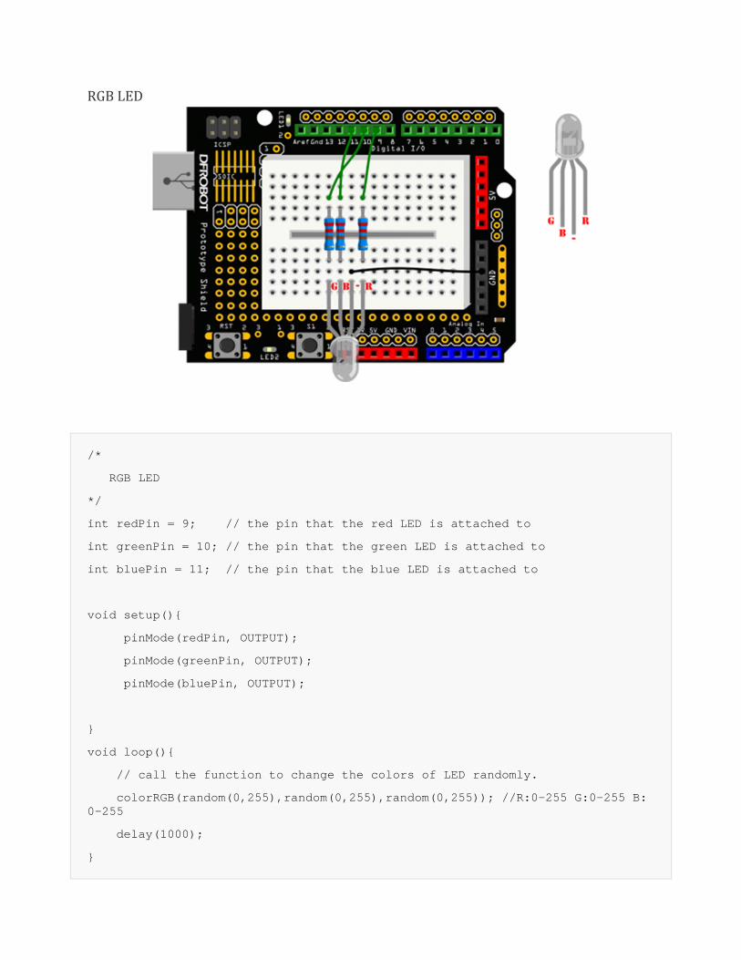
RGBLED
/*
RGB LED
*/
int redPin = 9; // the pin that the red LED is attached to
int greenPin = 10; // the pin that the green LED is attached to
int bluePin = 11; // the pin that the blue LED is attached to
void setup(){
pinMode(redPin, OUTPUT);
pinMode(greenPin, OUTPUT);
pinMode(bluePin, OUTPUT);
}
void loop(){
// call the function to change the colors of LED randomly.
colorRGB(random(0,255),random(0,255),random(0,255)); //R:0-255 G:0-255 B:0-255
delay(1000);
}
void colorRGB(int red, int green, int blue){
analogWrite(redPin,constrain(red,0,255));
analogWrite(greenPin,constrain(green,0,255));
analogWrite(bluePin,constrain(blue,0,255));
}
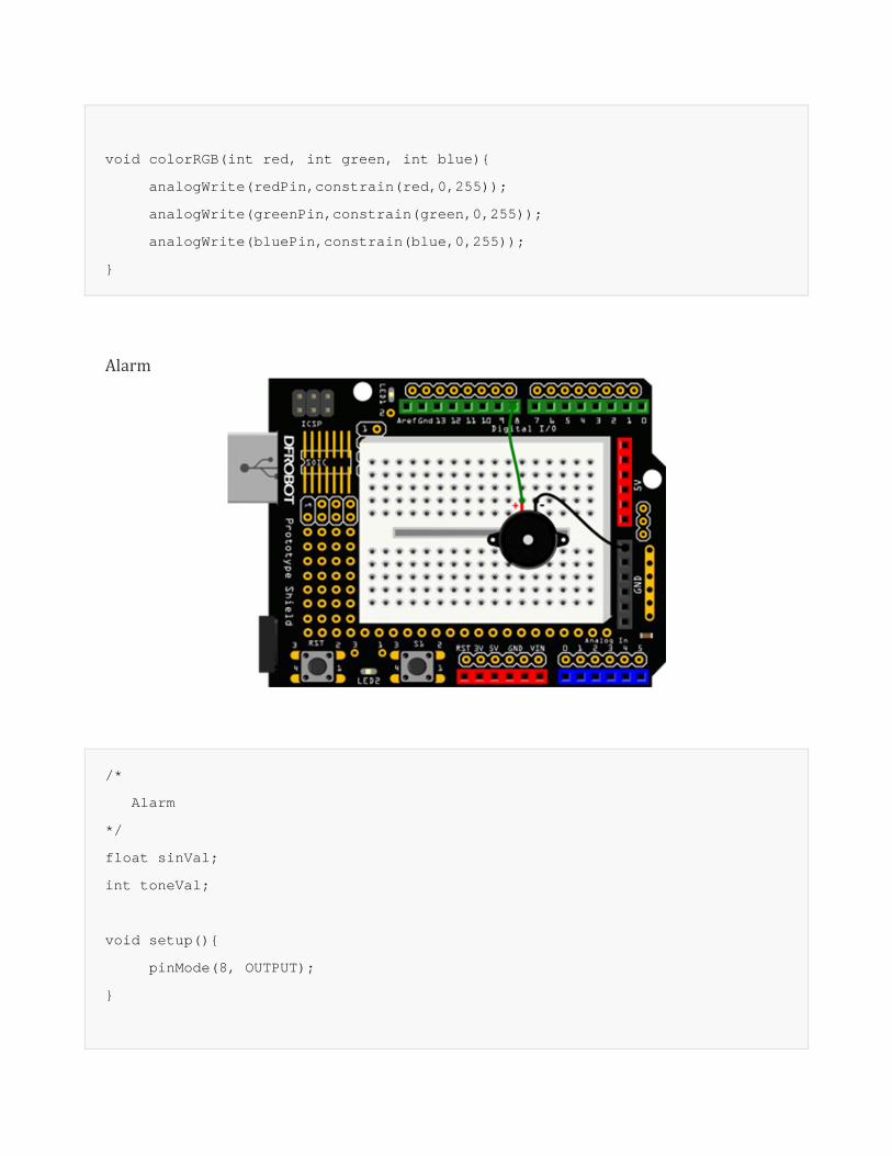
Alarm
/*
Alarm
*/
float sinVal;
int toneVal;
void setup(){
pinMode(8, OUTPUT);
}
void loop(){
for(int x=0; x<180; x++){
// convert degrees to radians then obtain value
sinVal = (sin(x*(3.1412/180)));
// generate a frequency from the sin value
toneVal = 2000+(int(sinVal*1000));
tone(8, toneVal);
delay(2);
}
}
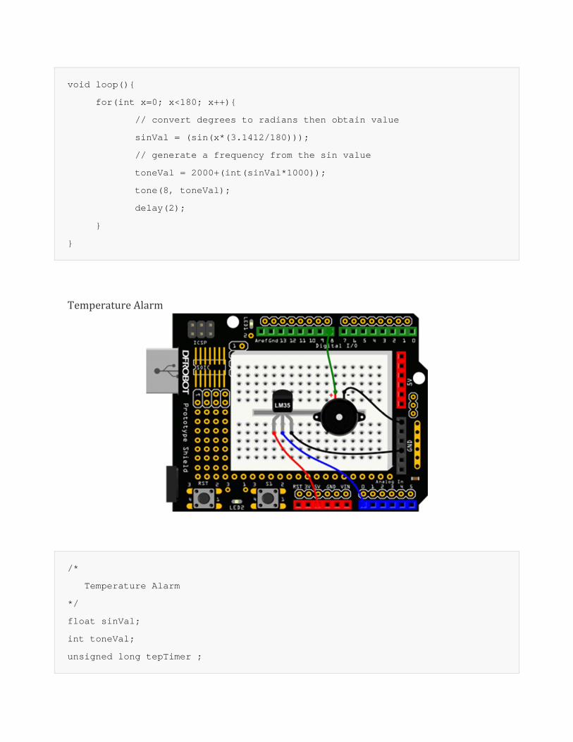
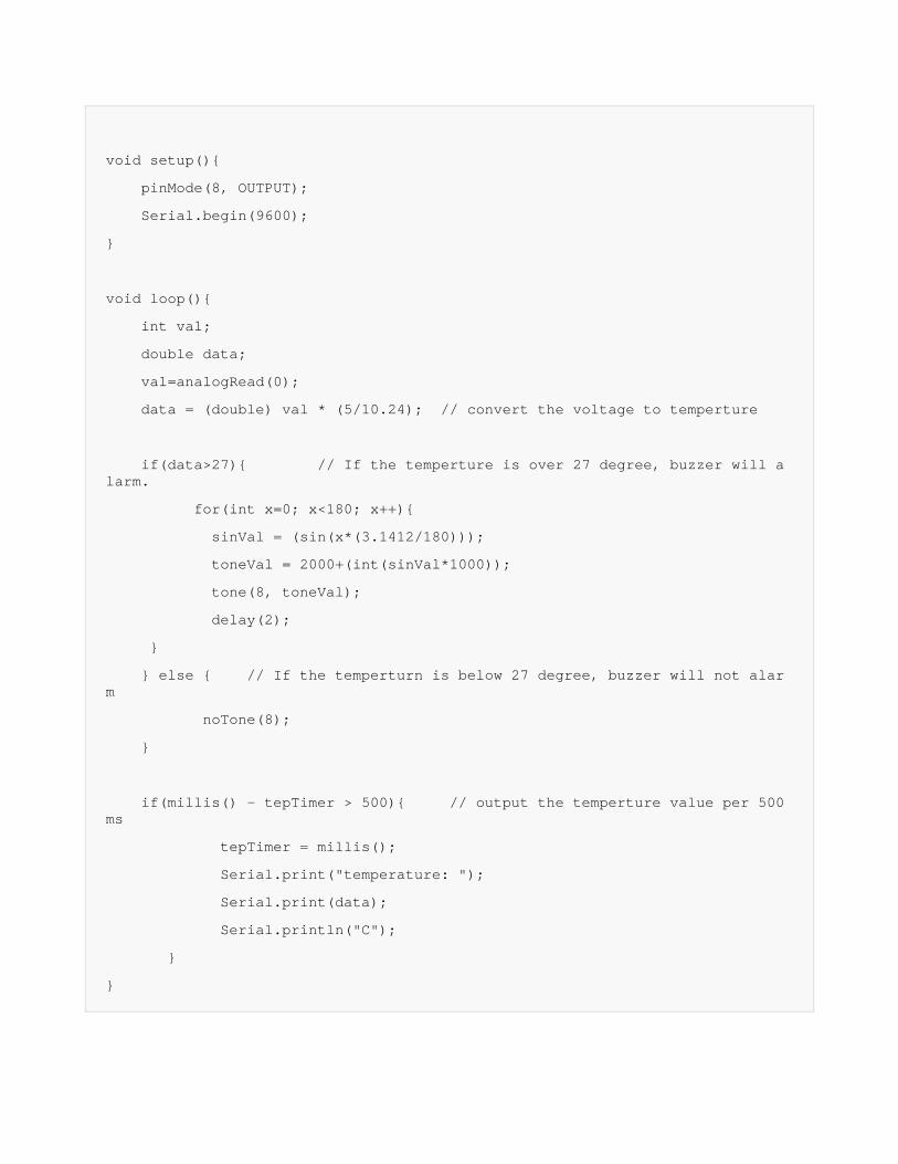
TemperatureAlarm
/*
Temperature Alarm
*/
float sinVal;
int toneVal;
unsigned long tepTimer ;
void setup(){
pinMode(8, OUTPUT);
Serial.begin(9600);
}
void loop(){
int val;
double data;
val=analogRead(0);
data = (double) val * (5/10.24); // convert the voltage to temperture
if(data>27){ // If the temperture is over 27 degree, buzzer will alarm.
for(int x=0; x<180; x++){
sinVal = (sin(x*(3.1412/180)));
toneVal = 2000+(int(sinVal*1000));
tone(8, toneVal);
delay(2);
}
} else { // If the temperturn is below 27 degree, buzzer will not alarm
noTone(8);
}
if(millis() - tepTimer > 500){ // output the temperture value per 500ms
tepTimer = millis();
Serial.print("temperature: ");
Serial.print(data);
Serial.println("C");
}
}
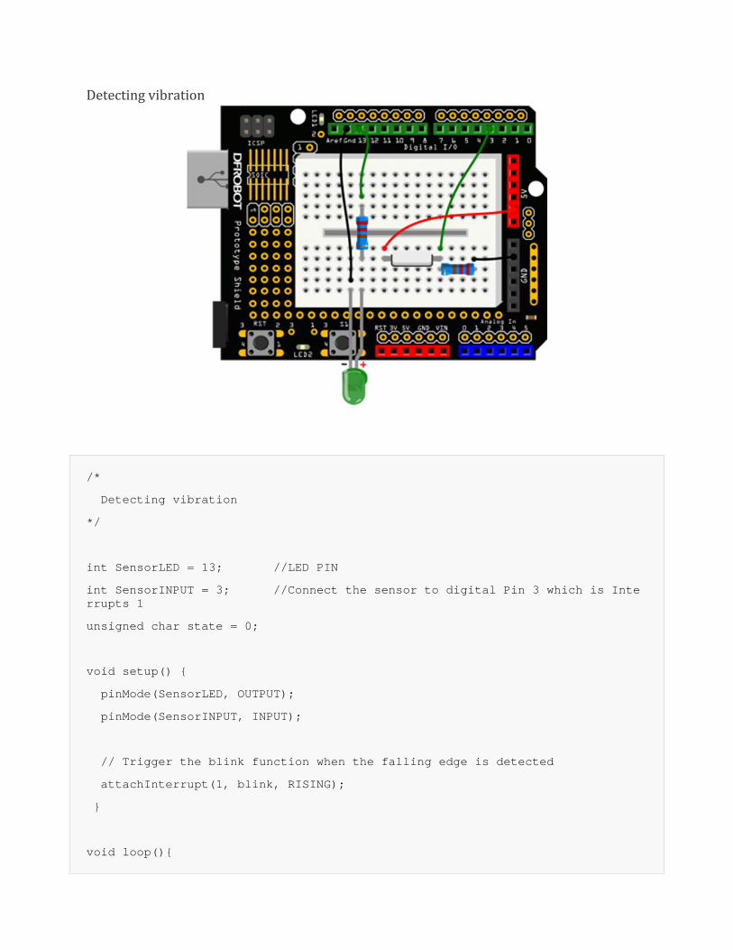
Detectingvibration
/*
Detecting vibration
*/
int SensorLED = 13; //LED PIN
int SensorINPUT = 3; //Connect the sensor to digital Pin 3 which is Interrupts 1
unsigned char state = 0;
void setup() {
pinMode(SensorLED, OUTPUT);
pinMode(SensorINPUT, INPUT);
// Trigger the blink function when the falling edge is detected
attachInterrupt(1, blink, RISING);
}
void loop(){
if(state!=0){
state = 0;
digitalWrite(SensorLED,HIGH);
delay(500);
}
else
digitalWrite(SensorLED,LOW);
}
void blink(){ //Interrupts function
state++;
}
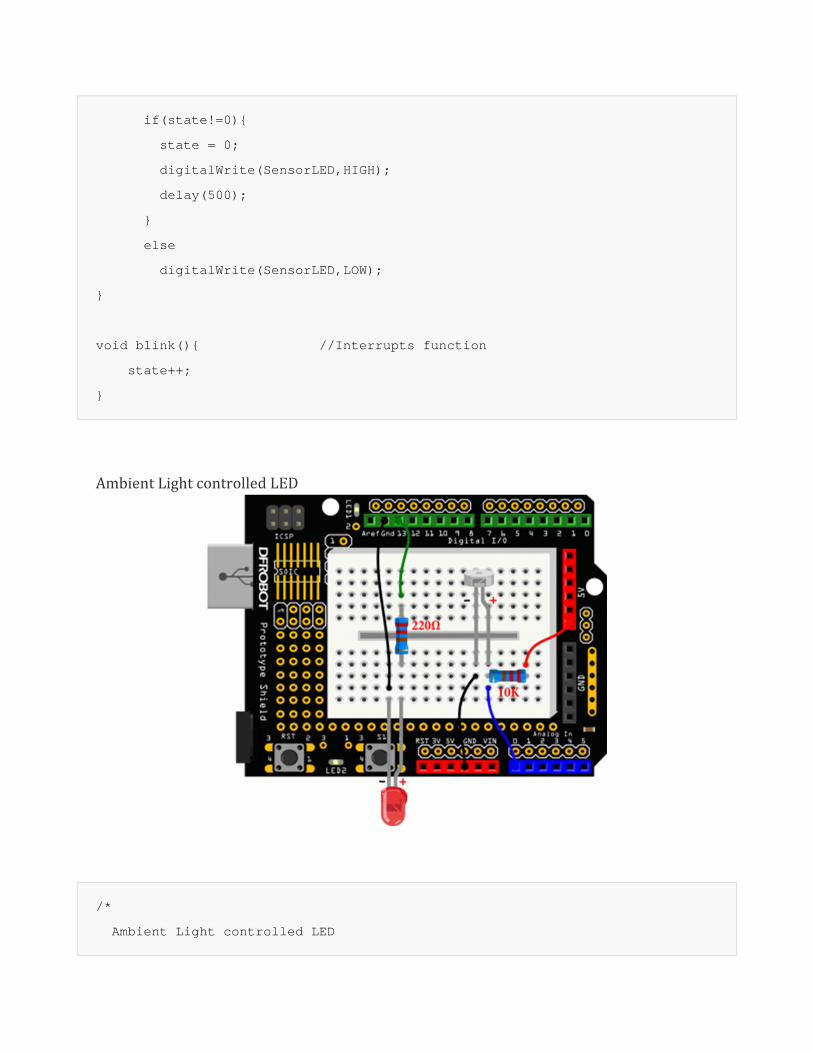
AmbientLightcontrolledLED
/*
Ambient Light controlled LED
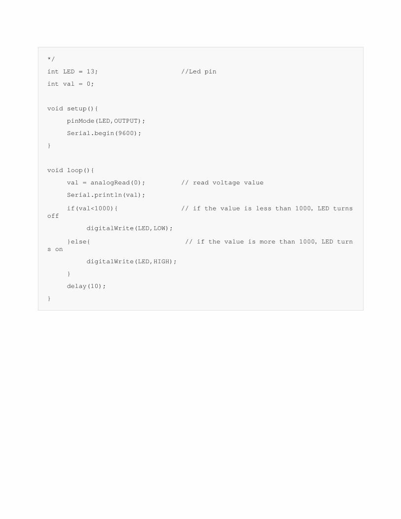
*/
int LED = 13; //Led pin
int val = 0;
void setup(){
pinMode(LED,OUTPUT);
Serial.begin(9600);
}
void loop(){
val = analogRead(0); // read voltage value
Serial.println(val);
if(val<1000){ // if the value is less than 1000,LED turns off
digitalWrite(LED,LOW);
}else{ // if the value is more than 1000,LED turns on
digitalWrite(LED,HIGH);
}
delay(10);
}
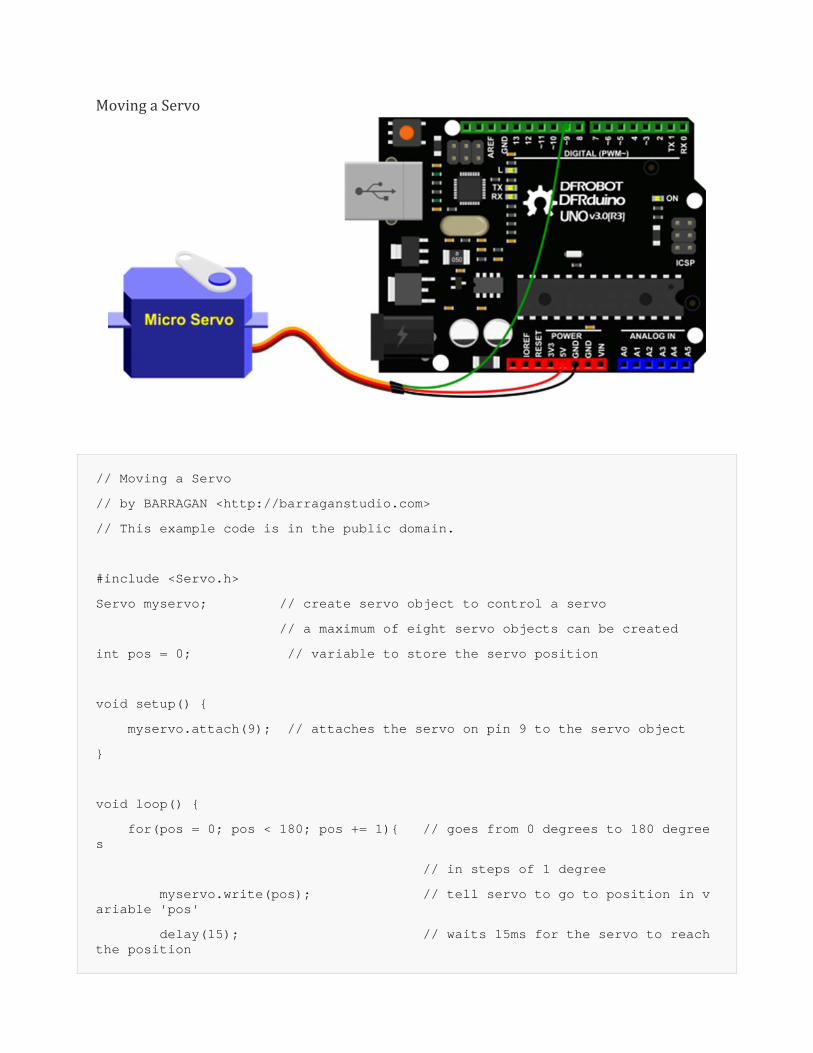
MovingaServo
// Moving a Servo
// by BARRAGAN <http://barraganstudio.com>
// This example code is in the public domain.
#include <Servo.h>
Servo myservo; // create servo object to control a servo
// a maximum of eight servo objects can be created
int pos = 0; // variable to store the servo position
void setup() {
myservo.attach(9); // attaches the servo on pin 9 to the servo object
}
void loop() {
for(pos = 0; pos < 180; pos += 1){ // goes from 0 degrees to 180 degrees
// in steps of 1 degree
myservo.write(pos); // tell servo to go to position in variable 'pos'
delay(15); // waits 15ms for the servo to reach the position
}
for(pos = 180; pos>=1; pos-=1) { // goes from 180 degrees to 0 degrees
myservo.write(pos); // tell servo to go to position in variable 'pos'
delay(15); // waits 15ms for the servo to reach the position
}
}
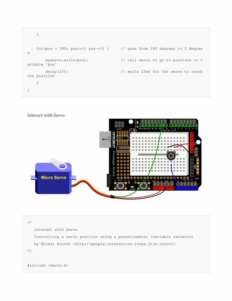
InteractwithServo
/*
Interact with Servo
Controlling a servo position using a potentiometer (variable resistor)
by Michal Rinott <http://people.interaction-ivrea.it/m.rinott>
*/
#include <Servo.h>
Servo myservo; // create servo object to control a servo
int potpin = 0; // analog pin used to connect the potentiometer
int val; // variable to read the value from the analog pin
void setup() {
myservo.attach(9); // attaches the servo on pin 9 to the servo object
}
void loop() {
val = analogRead(potpin); // reads the value of the potentiometer (value between 0 and 1023)
val = map(val, 0, 1023, 0, 179); // scale it to use it with the servo (value between 0 and 180)
myservo.write(val); // sets the servo position according to the scaled value
delay(15); // waits for the servo to get there
}
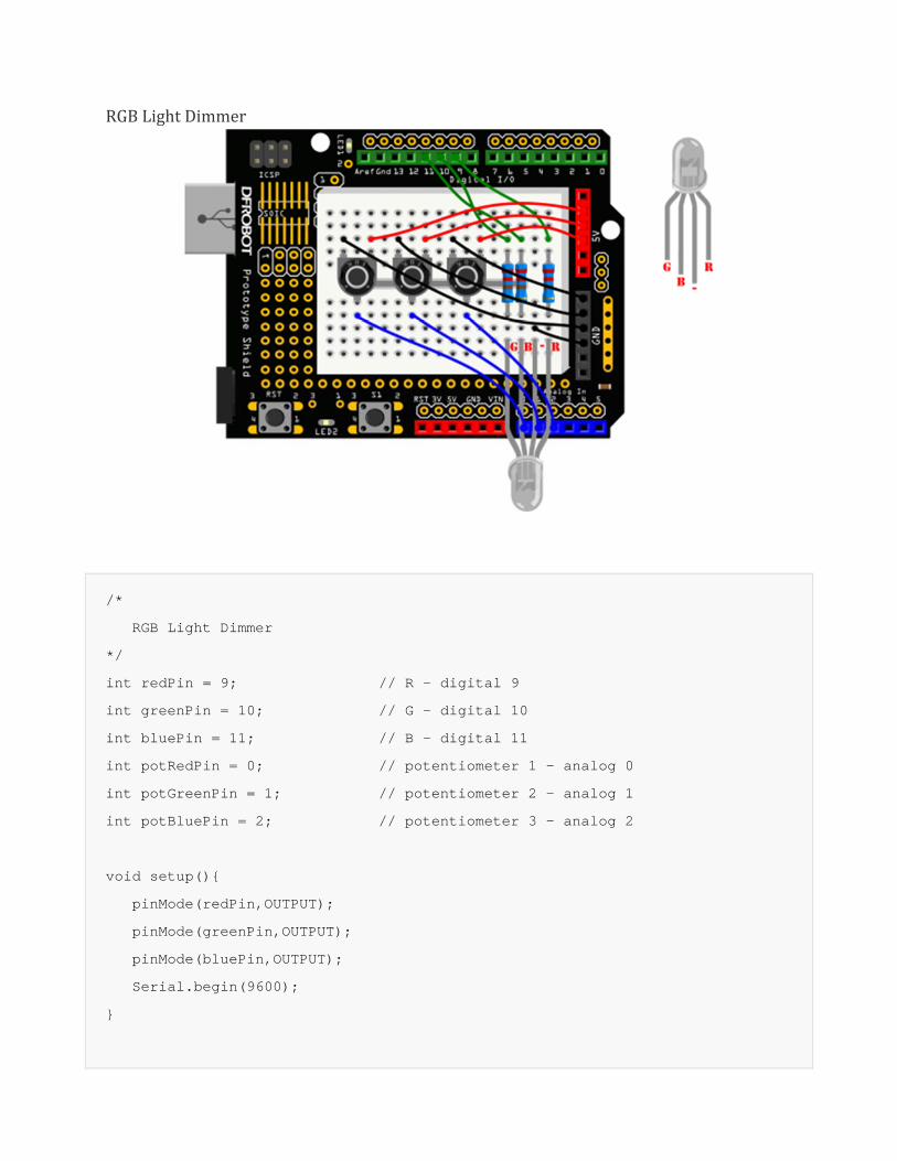
RGBLightDimmer
/*
RGB Light Dimmer
*/
int redPin = 9; // R – digital 9
int greenPin = 10; // G – digital 10
int bluePin = 11; // B – digital 11
int potRedPin = 0; // potentiometer 1 – analog 0
int potGreenPin = 1; // potentiometer 2 – analog 1
int potBluePin = 2; // potentiometer 3 – analog 2
void setup(){
pinMode(redPin,OUTPUT);
pinMode(greenPin,OUTPUT);
pinMode(bluePin,OUTPUT);
Serial.begin(9600);
}
void loop(){
int potRed = analogRead(potRedPin);
int potGreen = analogRead(potGreenPin);
int potBlue = analogRead(potBluePin);
int val1 = map(potRed,0,1023,0,255);
int val2 = map(potGreen,0,1023,0,255);
int val3 = map(potBlue,0,1023,0,255);
Serial.print("Red:");
Serial.print(val1);
Serial.print("Green:");
Serial.print(val2);
Serial.print("Blue:");
Serial.println(val3);
colorRGB(val1,val2,val3);
}
void colorRGB(int red, int green, int blue){
analogWrite(redPin,constrain(red,0,255));
analogWrite(greenPin,constrain(green,0,255));
analogWrite(bluePin,constrain(blue,0,255));
}
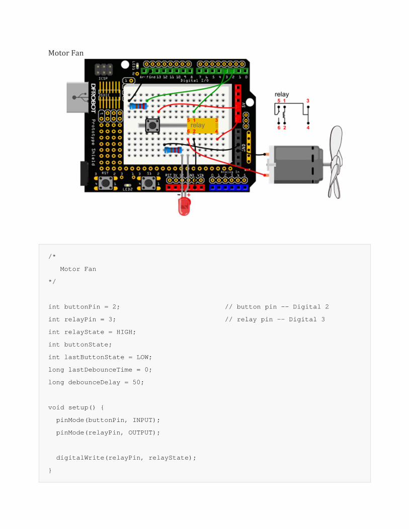
MotorFan
/*
Motor Fan
*/
int buttonPin = 2; // button pin -- Digital 2
int relayPin = 3; // relay pin -- Digital 3
int relayState = HIGH;
int buttonState;
int lastButtonState = LOW;
long lastDebounceTime = 0;
long debounceDelay = 50;
void setup() {
pinMode(buttonPin, INPUT);
pinMode(relayPin, OUTPUT);
digitalWrite(relayPin, relayState);
}
void loop() {
// read the state of the switch into a local variable:
int reading = digitalRead(buttonPin);
// check to see if you just pressed the button
// (i.e. the input went from LOW to HIGH), and you've waited
// long enough since the last press to ignore any noise:
// If the switch changed, due to noise or pressing:
if (reading != lastButtonState) {
lastDebounceTime = millis();
}
if ((millis() - lastDebounceTime) > debounceDelay) {
// whatever the reading is at, it's been there for longer
// than the debounce delay, so take it as the actual current state:
// if the button state has changed:
if (reading != buttonState) {
buttonState = reading;
// only toggle the Relay if the new button state is HIGH
if (buttonState == HIGH) {
relayState = !relayState;
}
}
}
// set the relay:
digitalWrite(relayPin, relayState);
// save the reading. Next time through the loop,
// it'll be the lastButtonState:
lastButtonState = reading;
}
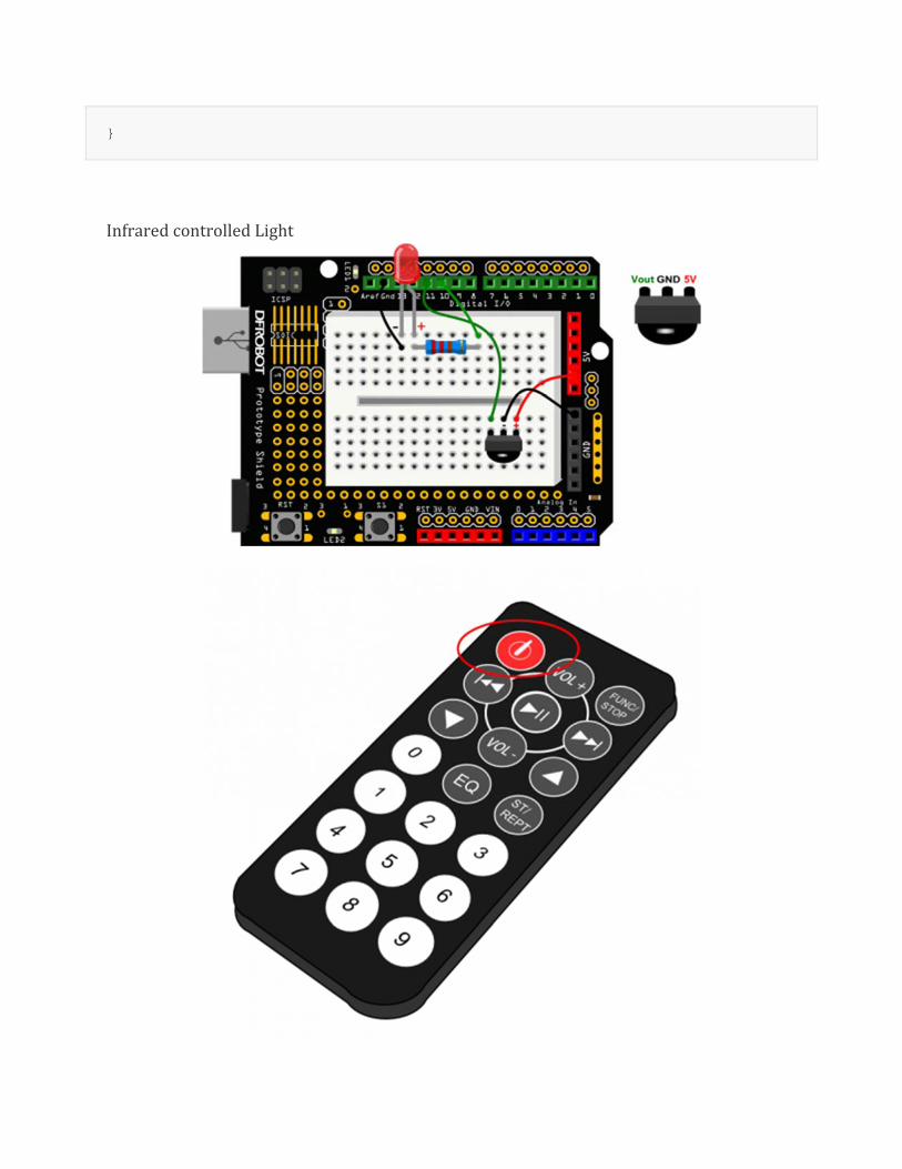
InfraredcontrolledLight
/*
Infrared controlled Light
*/
#include <IRremote.h>
int RECV_PIN = 11;
int ledPin = 10;
boolean ledState = LOW;
IRrecv irrecv(RECV_PIN);
decode_results results;
void setup(){
Serial.begin(9600);
irrecv.enableIRIn();
pinMode(ledPin,OUTPUT);
}
void loop() {
if (irrecv.decode(&results)) {
Serial.println(results.value, HEX);
if(results.value == 0xFD00FF){
ledState = !ledState;
digitalWrite(ledPin,ledState);
}
irrecv.resume();
}
}
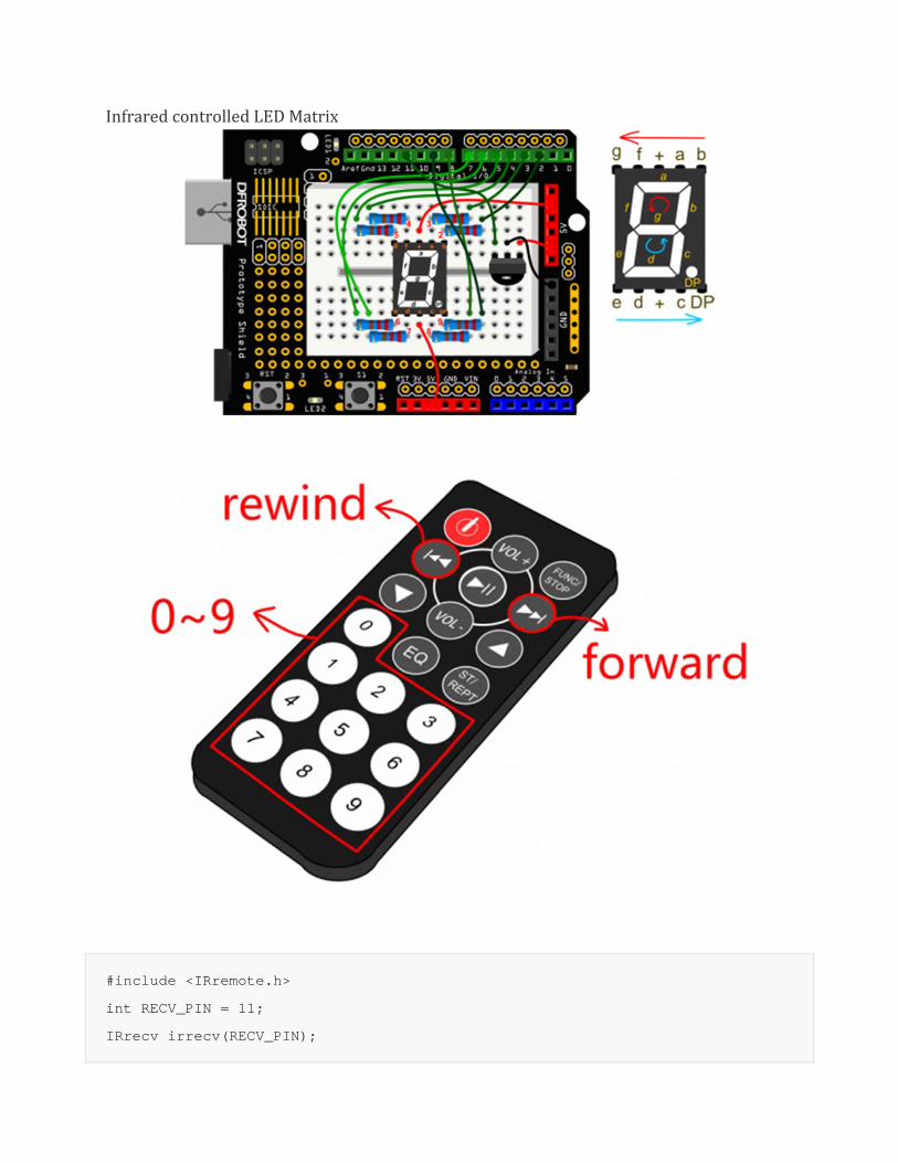
InfraredcontrolledLEDMatrix
#include <IRremote.h>
int RECV_PIN = 11;
IRrecv irrecv(RECV_PIN);
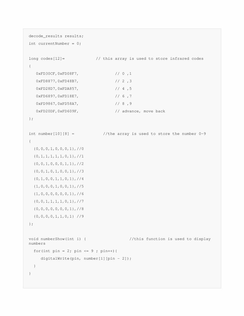
decode_results results;
int currentNumber = 0;
long codes[12]= // this array is used to store infrared codes
{
0xFD30CF,0xFD08F7, // 0 ,1
0xFD8877,0xFD48B7, // 2 ,3
0xFD28D7,0xFDA857, // 4 ,5
0xFD6897,0xFD18E7, // 6 ,7
0xFD9867,0xFD58A7, // 8 ,9
0xFD20DF,0xFD609F, // advance, move back
};
int number[10][8] = //the array is used to store the number 0~9
{
{0,0,0,1,0,0,0,1},//0
{0,1,1,1,1,1,0,1},//1
{0,0,1,0,0,0,1,1},//2
{0,0,1,0,1,0,0,1},//3
{0,1,0,0,1,1,0,1},//4
{1,0,0,0,1,0,0,1},//5
{1,0,0,0,0,0,0,1},//6
{0,0,1,1,1,1,0,1},//7
{0,0,0,0,0,0,0,1},//8
{0,0,0,0,1,1,0,1} //9
};
void numberShow(int i) { //this function is used to display numbers
for(int pin = 2; pin <= 9 ; pin++){
digitalWrite(pin, number[i][pin - 2]);
}
}
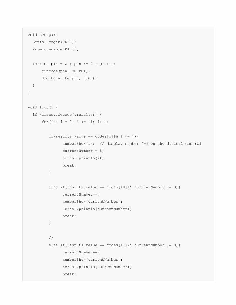
void setup(){
Serial.begin(9600);
irrecv.enableIRIn();
for(int pin = 2 ; pin <= 9 ; pin++){
pinMode(pin, OUTPUT);
digitalWrite(pin, HIGH);
}
}
void loop() {
if (irrecv.decode(&results)) {
for(int i = 0; i <= 11; i++){
if(results.value == codes[i]&& i <= 9){
numberShow(i); // display number 0~9 on the digital control
currentNumber = i;
Serial.println(i);
break;
}
else if(results.value == codes[10]&& currentNumber != 0){
currentNumber--;
numberShow(currentNumber);
Serial.println(currentNumber);
break;
}
//
else if(results.value == codes[11]&& currentNumber != 9){
currentNumber++;
numberShow(currentNumber);
Serial.println(currentNumber);
break;
}
}
Serial.println(results.value, HEX);
irrecv.resume();
}
}
FAQ Q. I have to say that I am loving the kit. I just wanted to let you know of an issue that I have encountered. In projects 11 and 12 of the kit, it requires the use of the 3 potentiometers. The problem is that the terminals of the potentiometers do not fit across into the sockets on the Prototyping Shield nor the provided breadboard. They are to wide.
A. Hello, your feedback is very precious to us.
Just as you said, the potentiometer couldn't be
inserted to the hole easily, but with some
strength to push it downward, it could be done.
I've attached a picture about it. Btw, we will
consider to upgrade it.
Powered By DFRobot © 2008-2017


![LDR/IR Beginner Robot Instruction Manual - EG …LDR/IR BEGINNER ROBOT INSTRUCTION MANUAL] EG Robotics Manual –Interested LLC 2012 7 | Page Step Five Put the Arduino on the chassis](https://img.dokumen.tips/doc/110x75/5b0352cf7f8b9a0a548bffa7/ldrir-beginner-robot-instruction-manual-eg-ldrir-beginner-robot-instruction.jpg)