Embed Size (px)
Citation preview
02/07/08 EEC 421/521: Software Engineering 1
EEC 421/521: SoftwareEngineering
Analysis Modeling - 2
02/07/08 EEC 421/521: Software Engineering 2
Data Flow Diagrams
Structured Analysis
• Models data elements
– Attributes
– Relationships
• Models processes that transformdata
Modeling Tools
• Data object diagrams
• ERD diagrams
• Data flow diagram
• Process narrative
modeled using
modeled using
A data flow diagram describes information flow among a set ofprocesses and actors.
A process narrative describes how a single process transformsinput data to output data.
1
*
02/07/08 EEC 421/521: Software Engineering 3
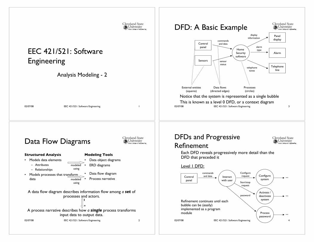
DFD: A Basic Example
Home Securitysoftware
Controlpanel
Sensors
Paneldisplay
Alarm
Telephoneline
commandsand data
sensorstatus
displayinformation
telephonetones
alarmtype
External entities(squares)
Data flows(directed edges)
Processes(circles)
Notice that the system is represented as a single bubble
This is known as a level 0 DFD, or a context diagram
02/07/08 EEC 421/521: Software Engineering 4
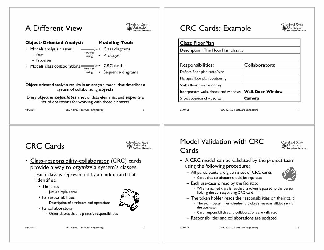
DFDs and ProgressiveRefinement
Each DFD reveals progressively more detail than theDFD that preceded it
Level 1 DFD:
Interactwith user
Controlpanel
commandsand data Configure
system
Configurerequest
Activate /deactivate
system
Start/stoprequest
Processpassword
…
password …
…
Refinement continues until eachbubble can be (easily)implemented as a programmodule

02/07/08 EEC 421/521: Software Engineering 5
Process Narrative
Processpassword
password
…
…
A process specification describes allof the flow processes in the final(most detailed) DFD.
A process specification can be represented as a collection ofprocess narratives.
“The process password transform performs password validation atthe control panel for the SafeHome security function. Process passwordreceives a four-digit password from the interact with user function.The password is first compared to the master password stored withinthe system …”
02/07/08 EEC 421/521: Software Engineering 6
DFD ConstructionGrammatical
parse
Developprocess
narratives
Level 0 DFDScopedocument
Grammaticalparse
Next levelDFD
(nouns = external entities, data/control objects, data stores)
(verbs = processes)
Note that nouns and verbs are associated with one another
02/07/08 EEC 421/521: Software Engineering 7
Some Guidelines
• Level 0 DFD must contain only a single bubble
• All arrows and bubbles should be meaningfullylabeled
• Refinement begins by isolating next levelprocesses, data objects, and data stores
• Refine only one bubble at a time
• Data flow continuity must be maintainedbetween levels
02/07/08 EEC 421/521: Software Engineering 8
Exercise: Data Flow Diagrams
Create a level 0 data flow diagram for abasic automated teller machine (ATM).
You can ignore administrative scenarios.
What would the level 1 data flowdiagram look like?
02/07/08 EEC 421/521: Software Engineering 9
A Different View
Object-Oriented Analysis
• Models analysis classes
– Data
– Processes
• Models class collaborations
Modeling Tools
• Class diagrams
• Packages
• CRC cards
• Sequence diagrams
modeled using
modeled using
Object-oriented analysis results in an analysis model that describes asystem of collaborating objects
Every object encapsulates a set of data elements, and exports aset of operations for working with those elements
02/07/08 EEC 421/521: Software Engineering 10
CRC Cards
• Class-responsibility-collaborator (CRC) cardsprovide a way to organize a system’s classes– Each class is represented by an index card that
identifies:• The class
– Just a simple name
• Its responsibilities– Description of attributes and operations
• Its collaborators– Other classes that help satisfy responsibilities
02/07/08 EEC 421/521: Software Engineering 11
CRC Cards: Example
CameraShows position of video cam
Wall, Door, WindowIncorporates walls, doors, and windows
Scales floor plan for display
Manages floor plan positioning
Defines floor plan name/type
Collaborators:Responsibilities:
Description: The FloorPlan class ...
Class: FloorPlan
02/07/08 EEC 421/521: Software Engineering 12
Model Validation with CRCCards• A CRC model can be validated by the project team
using the following procedure:– All participants are given a set of CRC cards
• Cards that collaborate should be separated
– Each use-case is read by the facilitator• When a named class is reached, a token is passed to the person
holding the corresponding CRC card
– The token holder reads the responsibilities on their card• The team determines whether the class’s responsibilities satisfy
the use-case
• Card responsibilities and collaborations are validated
– Responsibilities and collaborations are updated
02/07/08 EEC 421/521: Software Engineering 13
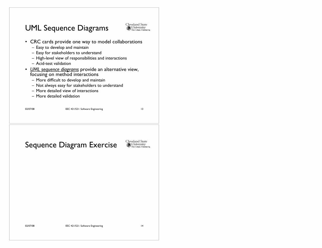
UML Sequence Diagrams
• CRC cards provide one way to model collaborations– Easy to develop and maintain– Easy for stakeholders to understand– High-level view of responsibilities and interactions– Acid-test validation
• UML sequence diagrams provide an alternative view,focusing on method interactions– More difficult to develop and maintain– Not always easy for stakeholders to understand– More detailed view of interactions– More detailed validation
02/07/08 EEC 421/521: Software Engineering 14
Sequence Diagram Exercise