Embed Size (px)
Citation preview

DeZURIK BHP HIGH PERFORMANCE BUTTERFLY VALVES
TECHNICAL SPECIFICATIONS
BULLETIN 45.00-2
NOVEMBER 2017

© 2017 DeZURIK, Inc. 2
Materials of Construction
Disc Pinning14" & larger (350mm & larger)
A3 Disc
A5 Pin

3
Packing Options
StandardPTFE V-Flex Packing (TC)
PTFE V-Flex, Dual Seal,Low Cycle Packing (TCD)
Standard Carbon Graphite (G1) Flexible Carbon Graphite (G2)
PTFE V-Flex, Dual Seal,Live Loaded, Low Cycle Packing (TCDL)
PTFE V-Flex Packing,Live Loaded, Low Cycle (TCL)
Flexible Carbon Graphite, High Cycle Live Loaded (G2L)
Flexible Carbon Graphite, Dual Seal,High Cycle Packing (G2D)
Flexible Carbon Graphite, Dual Seal,Live Loaded, High Cycle Packing (G2DL)

4
Item Description Material
A1 BodyCarbon Steel, ASTM A216, Grade WCB316 Stainless Steel, ASTM A351, Grade CF8M317 Stainless Steel, ASTM A351, Grade CG-3M except with .03% max carbon
A2 Bearing
PTFE Fabric with 317 Stainless Steel Backing, to 500°F (260°C)316 Stainless Steel, Diffusion Hardened, to 700°F (371°C)Nickel Stainless Steel ASTM A494, Grade CY5SnBiM, to 700°F (371°C)316 Stainless Steel Nickel Coated, Heat Treated, to 700°F (371°C)316 Stainless Steel, Diffusion Hardened, to 700°F (371°C)PTFE Fabric with Hastelloy C Backing, to 500°F (260°C)
A3 Disc316 Stainless Steel, ASTM A351, Grade CF8M316 Stainless Steel, ASTM A351, Grade CF8M, Nickel Overlay, Heated Treated to RC70317 Stainless Steel, ASTM A351, Grade CG-3M except with .03% max carbon
A4 Shaft2205 Duplex Stainless Steel, ASTM A276 Type 220517-4 PH Stainless Steel, ASTM A 564, Type 630, Cond H1150 per NACE MR-01-75316 Stainless Steel, ASTM A479, Type 316
A5 PinNitrogren-Strengthened Austenitic Alloy ASTM A479, Type XM-19, Condition A, to NACE MR0175/ISO 15156316 Stainless Steel, ASTM A276, Type 316, Flash Chrome Plate
A9 Pipe PlugCarbon Steel, ASTM A216, Grade WCB, Galvanized316 Stainless Steel, ASTM A351, Grade CF8M317 Stainless Steel, ASTM A240, Type 317
A10 Packing Washer
316 Stainless Steel, ASTM A240, Type 316316 Stainless Steel, ASTM A276, Type 316, Condition A316 Stainless Steel, ASTM A511, Type 316317 Stainless Steel, A167, Type 317
A11 PackingPTFE, V-Flex Carbon Graphite
A12 Packing Gland317 Stainless Steel, ASTM A351, Type 317316 Stainless Steel, ASTM A511, Grade MT316
A14 Stud 316 Stainless SteelA15 Gland Nut 316 Stainless SteelA16 Gasket Carbon Graphite/Stainless SteelA19 Pipe Plug 316 Stainless Steel
A20 Seat RetainerCarbon Steel, ASTM A516, Grade 70 or ASTM A216, Grade WCB316 Stainless Steel, ASTM A240, Type 316 or ASTM A351, Grade CF8M317 Stainless Steel, ASTM A240, Type 317
A21 Resilient SeatPTFE, White VirginRTFE, 10% Carbon Graphite Filled PTFE
A22 Seat Control RingTitanium, ASTM B265, Grade 3Nickel-Chromium Alloy
A23 Screw316 Stainless Steel317 Stainless Steel
A24 Set Screw316 Stainless Steel317 Stainless Steel, ASTM A167, Type 317
A27 Gasket Carbon Graphite, Commercial Grade GTBA28 Metal Seat Ring 316 Stainless Steel, ASTM A240, Type 316, Condition A
A30 SealPTFECarbon Graphite, Commercial Grade GTB
A31 CoverCarbon Steel, ASTM A516, Grade 70316 Stainless Steel, ASTM A240, Type 316, Condition A
A32 Lock Washer410 Stainless Steel316 Stainless Steel
A33 Screw Stainless Steel, ASTM A193, Grade B8M, Class 1 or 2A34 Anti-Extrusion Washer PTFE/317 Stainless Steel (See page 7)A37 Washer Steel, Zinc Plated (See page 7)
A42 Lock Washer410 Stainless Steel316 Stainless Steel
A46 Retaining Ring 303 Series Stainless Steel
Materials of Construction

Valve SelectionApplicable Standards
DeZURIK BHP High Performance Butterfly Valves are designed and/or tested to meet the following standards:
ASME B16.1
Cast Iron Pipe Flanges and Flanged Fittings. Class 150 valves mate with pipeline flanges conforming to the Class 125 requirements and Class 300 valves are designed to mate with Class 250 pipe flanges.
ASME B16.20
Metallic Gaskets for Pipe Flanges Ring-Joint, Spiral-Wound, and Jacketed. End connections compatible (within the limits of API 609) with spiral-wound gaskets in accordance with API 601 gaskets. Optional undrilled seat retainer (UR) construction available to provide full seal area contact with API 601 gaskets.
ASME B16.34 Valves-Threaded and Welded End. All BHP Butterfly Valves comply with requirements of this standard.
ASME B16.47
Pipe Flanges and Flanged Fittings. Class 150, Series A, Table I-29; Class 300, Series A, Table I-30. Sizes 28" (700mm) and larger are designed to mate with pipeline flanges conforming to the Series A requirements, Large Diameter Steel Flanges.
ASME B16.5 Pipe Flanges and Flanged Fittings. 2–24" (80-300mm) valves are designed to mate with Class 150 or 300 flanges.
ANSI/FCI 70-2
Control Valve Seat Leakage. Metal-seated valves conform to the Class IV leak rate requirements. All valves are tested to Class IV. If Class V is required, it must be specified as an option to allow for test differences. PTFE and RTFE seat options meet or exceed Class VI requirements.
API 598 Seat/Shell Test. Resilient and Dual Seated Valves meet the leak rate requirements of this standard.
API 607Fire Test for Soft Seated, Quarter-Tum Valves, 6th Edition. Valves with Fyre-Block (FB) option conform to this requirement.
API 609
Face-to-face dimensions for 3-24" valves conform to Category B Class 150 and Class 300 requirements (Sizes 2", 2.5" and 5" are not named in this standard). Class 150 sizes 28" and larger conform to the requirements of Category A.
AWWA C207 Class 150, Class D (175-150 psi), Table 3 and Class E (275 psi) Table 4.
BS 4504 Conforms to flange bolt guide and pressure ratings.
BS 5146
Inspection and Test of Steel Valves for the Petroleum, Petrochemical and Allied Industries. Dual Seated valves with Fyre-Block (FB) option meet with fire portion of standard.
DIN 2632 Conforms to flange bolt guides and pressure 2635 ratings.
DIN 3230 Leak Rate 1 Requirement. Resilient and Dual Seated Valves meet the leak rate requirements of this standard.
EN 29001 DeZURIK manufacturing processes comply with this quality standard.
ISA D79.01 Level 2 Leak Rates Cryogenic Tests ISA A75.02 Standard Control Valve Capacity Test Procedure.
ISO 5208 Conforms to pressure testing requirements of this standard.
ISO 5211 Conforms to flange bolt guide and pressure ratings.
ISO 5752 All valves designed to comply with face-to-face dimensions.
ISO 7005 Conforms to flange bolt guide and pressure ratings.
ISO 9001 DeZURIK manufacturing processes certified to this quality standard.
JIS B2212 Conforms to flange bolt guide and pressure ratings.
MSS SP-25Standard Marking System for Valves, Fittings, Flanges, and Unions. All valves comply with requirements of this standard.
MSS SP-44 Steel Pipeline Flanges, Class 150, Annex C, Table C3; Class 300, 740 psi, Annex C, Table C4.
MSS SP-61 Pressure Testing of Steel Valves.
MSS SP-68 High Pressure Offset Seat Butterfly Valves. All valves comply with the requirements of this standard.
NACE MR0175
Sulfide Stress Cracking Resistant Metallic Material for Oil Field Equipment. NACE trim is standard on all valves except metal seated. This construction available as an option with metal seated valves.
NSF/ANSI-61 Certified to NSF/ANSI-61 Drinking Water System Components.
NSF/ANSI-372Certified to NSF/ANSI-372 with requirements for Lead-free as defined by CA, VT, MD, LA state laws and the US Safe Drinking Water Act.
PED Pressure Equipment Directive
Quality System for the design, manufacture, final inspection and testing meet provisions of the directive.
Shut-Off Capabilities
Seat Type Shutoff Capability
PTFE & RTFE Seated Bubble-Tight Shutoff with pressure on either side of the disc
Dual Seated Class VI - DIN 1 Bubble-Tight Shutoff
Metal SeatedStandard, Class IV unidirectional on seat side. With optional C5, Class V unidirectional on seat side.
5

6
Pressure Ratings (Ambient Temperature)
Body Material/Class Pressure RatingCarbon Steel, Class 150 285 psi (1960 kPa)
Carbon Steel, Class 300 740 psi (5100 kPa)
Stainless Steel, Class 150 275 psi (1890 kPa)
Stainless Steel, Class 300 720 psi (4960 kPa)
Pressure/Temperature Curves
Metal Seat
Metal Seat Lower Temp. Limit
Metal Seat Upper Temp. Limit
ANSI Class 150
ANSI Class 300
Stainless SteelCarbon Steel
0
8005510
7004820
6004130
5003450
4002760
3002070
2001380
100690
Pres
sure
, psi
/kPa
Temperature, ºF/ºC
-100-73
-20-29
032
10038
20093
300149
400204
500260
600316
700371
25 psi 170 kPa
74051007204960
2751890
2851960
Temperature, ºF/ºC
Pres
sure
, psi
/kPa
ANSI Class 150
ANSI Class 300
(TT, TI, TTS2, TIS2)(RT, RI, RTS2, RIS2)
(TT, TI, TTS2, TIS2)(RT, RI, RTS2, RIS2)
0
8005510
7004820
6004130
5003450
4002760
3002070
2001380
100690
-100-73
-20-29
032
10038
20093
300149
400204
500260
600316
700371
25 psi 170 kPa
74051007204960
2751890
2851960
Resilient and Dual Seats

7
Valve Selection
Valve Size
Class 150 Class 300
Cv*/Kv*100% Open
K Factor**Cv*/Kv*
100% Open
K Factor**
2"50mm
8574 2.25 85
74 1.74
2.5"65mm
180156 1.02 160
138 1.01
3"80mm
275238 1.04 260
225 0.93
4"100mm
520450 0.87 475
411 0.85
5"125mm
860744 0.78 770
666 0.81
6"150mm
13601176 0.65 1130
977 0.77
8"200mm
22601955 0.71 2110
1825 0.68
10"250mm
35503071 0.71 3350
2898 0.66
12"300mm
50004325 0.72 4800
4152 0.65
14"350mm
68005882 0.57 6390
5527 0.53
16"400mm
90007785 0.56 8460
7318 0.52
18"450mm
1180010207 0.52 11100
13500 0.49
20"500mm
1440012456 0.54 13500
11678 0.51
24"600mm
2000017300 0.58 17700
15311 0.61
28"700mm
2700023355 0.67 Contact DeZURIK
30"750mm
3330028805 0.53 26300
22750 0.74
36"900mm
5650048873 0.40 47000
40655 0.51
42"1050mm
6700057955 0.53
Contact DeZURIK48"
1200mm10300089095 0.39
54-60"1400-1500mm Contact DeZURIK
Flow Parameters Flow Characteristics
*Cv = Flow in GPM of water at 1 psi pressure drop. Kv = Flow in m3/hr. of water at 100 kPa pressure drop.** K = The resistance coefficient of the valve. The constant (K)
can be used to determine the equivalent length of pipe.
L= KxD Where L = Equivalent length of pipe in feet f K = Resistance coefficient D = Pipe diameter in feet f = Friction factor, related to type of pipe
100%
90%
80%
70%
60%
50%
40%
30%
20%
10%
0%0% 10% 20% 30% 40% 50% 60% 70% 80% 90% 100%
Per
cen
t o
f M
axim
um
Flo
w
Valve Percent Open

8
Valve Size
Wafer Body
Lugged Body
2"50mm
32
74
2.5"65mm
42
95
3"80mm
105
115
4"100mm
115
199
5"125mm
189
2612
6"150mm
2210
4521
8"200mm
3617
4621
10"250mm
6128
6731
12"300mm
10046
14566
14"350mm
14265
18886
16"400mm
19288
243111
18"450mm
314143
363165
20"500mm
411187
335152
24"600mm
665302
800363
28"700mm Contact DeZURIK
30"750mm
975443
1175534
36"900mm
1560708
1900863
42"1050mm
Contact DeZURIK
45072045
48"1200mm
40151822
45452063
54-60"1400-1500mm Contact DeZURIK
Valve Size
Wafer Body
Lugged Body
2"50mm
42
115
2.5"65mm
63
189
3"80mm
84
2110
4"100mm
147
3516
5"125mm
2512
4923
6"150mm
2813
6430
8"200mm
4923
11050
10"250mm
7936
17580
12"300mm
12457
230105
14"350mm
18283
232106
16"400mm
246112
312142
18"450mm
402183
465211
20"500mm
525239
613279
24"600mm
736334
1025466
30"750mm Contact
DeZURIK
30001362
36"900mm
43501974
WeightsBasic Valve, Class 150 Basic Valve, Class 300
Note: Weights are approximate and do not include crating.PoundsKilograms

9
Valve StyleGive valve style code as follows: BHP = High Performance Butterfly Valve
Valve SizeGive valve size code as follows: 2 = 2" (50mm) 18 = 18" (450mm) 2.5 = 2.5" (65mm) 20 = 20" (500mm) 3 = 3" (80mm) 24 = 24" (600mm) 4 = 4" (100mm) 28 = 28" (700mm) 5 = 5" (125mm) 30 = 30" (750mm) 6 = 6" (150mm) 36 = 36" (900mm) 8 = 8" (200mm) 42 = 42" (1050mm) 10 = 10" (250mm) 48 = 48" (1200mm) 12 = 12" (300mm) 54 = 54" (1400mm) 14 = 14" (350mm) 60 = 60" (1500mm) 16 = 16" (400mm)
End ConnectionGive end connection code as follows:
Class 150 Wafer W1 = ASME W110 = DIN 10 or BS4504/10 Drilling W116 = DIN 16 or BS4504/16 Drilling W1D = B.S. Table D Drilling W1E = B.S. Table E Drilling W1J1 = JIS 10 Drilling
Class 150 Lugged L1 = ASME L110 = DIN 10 or BS4504/10 Drilling L116 = DIN 16 or BS4504/16 Drilling L1D = B.S. Table D Drilling L1E = B.S. Table E Drilling L1J1 = JIS 10 Drilling
Class 300 Wafer W2 = ASME W225 = DIN 25 or BS4504/25 Drilling W240 = DIN 40 or BS4504/40 Drilling W2F = B.S. Table F Drilling W2H = B.S. Table H Drilling W2J = B.S. Table J Drilling W2J2 = JIS 20 Drilling
Class 300 Lugged L2 = ASME L225 = DIN 25 or BS4504/25 Drilling L240 = DIN 40 or BS4504/40 Drilling L2F = B.S. Table F Drilling L2H = B.S. Table H Drilling L2J = B.S. Table J Drilling L2J2 = JIS 20 Drilling
Body MaterialGive body material code as follows: CS = Carbon Steel S2 = 316 Stainless Steel S3 = 317 Stainless Steel (3-12" except 5" Class 150 Lugged only)
On Application AA = Alloy 20 HC = Hastelloy C ML = Monel T3 = Titanium Grade 3
Packing MaterialGive packing material code as follows: TC = PTFE V-Flex, to 500°F (260°C) G1 = Carbon Graphite to 700°F (371°C)
Special Packing G2 = Flexible Graphite to 1000°F (538°C) TCD = PTFE V-Flex, Dual Seal, Low Cycle to 500°F (260°C) TCDL = PTFE V-Flex, Dual Seal, Live Loaded, Low Cycle to 500°F (260°C) TCL = PTFE V-Flex, Live Loaded, Low Cycle to 500°F (260°C) G2D = Flexible Graphite, Dual Seal, High Cycle to 1000°F (538°C) G2L = Flexible Graphite, Live Loaded, High Cycle to 1000°F (538°C) G2DL = Flexible Graphite, Dual Seal, Live Loaded, High Cycle to 1000°F (538°C)
Trim CombinationDisc Material Give disc material code as follows: S2 = 316 Stainless Steel S2NH = 316 Stainless Steel Nickel Plated Heat Treated
(must use 17-4 PH Shaft material) S3 = 317 Stainless Steel
(used with S10 Shaft, FT bearings and TT, TI, RT or RI seat)
On Application AA = Alloy 20 CSN = Carbon Steel Nickel Coated (24" and larger only) CSNH = Carbon Steel Nickel Coated Heat Treated (24" and larger only)
(must use 17-4 PH Shaft material) HC = Hastelloy C ML = Monel TN3 = Titanium Grade 3 (anodized)
Shaft Material (2-20") Give shaft material code as follows: S10 = 2205 Duplex S10B = 2205 Duplex (used only with L1 end connection, CS or S2
body material & TT, TI, RT or RI seat) S5A = 17-4 PH Stainless Steel
Shaft Material (24-60") S2 = 316 Stainless Steel S5 = 17-4 PH Stainless Steel
On Application (all sizes) AA = Alloy 20 HC = Hastelloy C ML = Monel T5C = Titanium Grade 5 (ceramic coated)
Bearing Material Give bearing material code as follows: FT = PTFE Fabric with 317 Stainless Steel Backing, to 500°F (260°C)NS = 316 Stainless Steel, Diffusion Hardened, to 700°F (371°C) Sizes 2-20" NS = Nickel Stainless Steel ASTM A494, Grade CY5SnBiM, to 700°F (371°C)
Sizes 24" and LargerNS = 316 Stainless Steel Nickel Coated, Heat Treated, to 700°F (371°C)
Used with NT optionS2 = 316 Stainless Steel, Diffusion Hardened, to 700°F (371°C) 24" and
Larger with NSF option
On Application FH = PTFE Fabric with Hastelloy C Backing, to 500°F (260°C)
Seat Seal/Seat Control Ring Material Give seat material code as follows: Standard Seats TT = PTFE/Titanium to 450°F (232°C) TTS2 = PTFE/Titanium and 316 Stainless Steel to 450°F (232°C) S2 = 316 Stainless Steel, to 700°F (371°C), must use Graphite packing and NS
bearings or to 450°F (232°C), recommended with TC packing and FT bearing. Not available on 5" valve.
Special Seats TI = PTFE/Nickel-Chromium Alloy, to 450°F (232°C). For oxygen service. TIS2 = PTFE/Nickel-Chromium Alloy and 316 Stainless Steel, to 450°F (230°C).
For oxygen service. RT = Reinforced PTFE/Titanium, to 500°F (260°C) RTS2 = Reinforced PTFE/Titanium and 316 Stainless Steel, to 500°F (260°C) RI = Reinforced PTFE/Nickel-Chromium Alloy, to 500°F (260°C) RIS2 = Reinforced PTFE/Nickel-Chromium Alloy and 316 Stainless Steel,
to 500°F (260°C)Note: Any seat seal/seat control ring combination with S2 seat is not available in
5" (125mm) or 54" (1400mm) sizes.
OrderingTo order, simply complete the valve order code from information shown. An ordering example is shown for your reference.

10
Ordering (Continued)
Options Give options code as follows: NSF = Certified to NSF/ASME Standard 61 Drinking Water System Components FB = Conforms to ASME/API 607 Sixth Edition Fire Test for Soft-Seated
Quarter Turn Valves. API 607 Sixth Edition does not cover the testing requirements for valve actuators other than manually operated gear boxes or levers.
BAA = Buy American Act CRT = Certified Material Physical & Chemical Test Report CMC = Certificate of Material Conformance DTR = DeZURIK Standard Certified Production Hydrostatic Shell
and Seat Test Report UR = Undrilled Seat Retainer - Available on 2-10" lugged valves only.
Not rated for dead end service. C5 = Class 5 Seat Test for (S2) metal seated valves per ASME B16.104/FCI70.2 15 = 150 psi Disc - 36" & Larger (Not available with Dual Seat, Fyre Block
or Metal Seats) NT = ANSI/NACE MR0175/ISO 15156, Petroleum and natural gas industries,
Materials for use in H2S-containing environments in oil and gas production. Specify (NT) NACE Trim when NS bearings are ordered. All other combinations are NACE Certified as standard.
API = Conforms to API-609 Butterfly Valves: Double Flanged, Lug- and Wafer-Type and API-598 Valve Inspection and Testing. Conformance to these API standards do not apply to valves with the (S2) metal seat because of allowable seat leak rate or valve sizes 2", 2.5" or 5".
On Application — = Pressure Equipment Directive (CE Mark)
Ordering ExampleBHP,6,W1,CS,TC,S2-S10-FT-TT*Actuator NOTE: For High Temperature Service, the limiting factor in valve
selection is the lowest temperature rating of the packing, bearing or seat seal material.

Valve Size
Order Code
Maximum Shutoff Pressure Differential psi/kPa
TT/TIRT/RI
TTS2/TIS2RTS2/RIS2
S2/TTS2 & FBRTS2 & FB
2-6"50-150mm LT 285
19602851960
2851960
8"200mm LT 285
19602851960
50340
Note: Stainless Steel valves are rated to 275 psi (1890 kPa).
Note: Stainless Steel valves are rated to 720 psi (4960 kPa).
Ordering Example:BHP,3,L1,S2,TC,S2-S10B-FT-TT*LT
Lever Actuator SizingClass 150
Valve Size
Order Code
Maximum Shutoff Pressure Differential psi/kPa
TT/TIRT/RI
TTS2/TIS2RTS2/RIS2
S2/TTS2 & FBRTS2 & FB
2 & 4"50 &
100mmLT 740
51007405100
7405100
6"150mm LT 740
51006504480
3002070
8"200mm LT 740
51004503100
50340
Class 300
11
Manual Actuators10-Position LeversA 10-position dial provides positive latching in open, closed and eight intermediate positions. A pointer indicates position of disc plus a notch in the handle allows use of a padlock to prevent unauthorized valve operation.
MountingLever actuators can be mounted at standard and 180° clockwise from standard. Specify mounting positions other than standard below the valve and actuator identification.
OrderingTo order, add lever code LT to basic valve identifica-tion. Lever actuators available on 2–8" (50–200mm) Class 150 and Class 300 valve sizes only. Handwheel actuators are recommended for valve sizes over 6" (150mm) and where water hammer may occur due to a sudden valve closure. Maximum pipeline velocity for lever operated valve is 20 feet (6 meters) per second.
Memory StopAn adjustable memory stop is available which allows return of the valve to preset open position after shutoff. Order the memory stop as part of a complete valve, by adding “ST” after the actuator code.
Ordering Example:BHP,3,L1,S2,TC,S2-S10B-FT-TT*LT,ST
Standard Mounting
180° Clockwise

MG Manual Gear ActuatorsManual gear actuator housings are constructed of high strength metal and feature sintered bronze bearings on each end of the input shaft for durability and performance. The high strength gear provides strength for robust appli-cations and a long service life without maintenance. All manual gear actuators feature external position indication and are available with safety lockout devices. Actuators for buried service are available as an option.
G-Series Manual and Cylinder ActuatorsRotary manual actuators feature a cast iron housing with bearings on each end of the input shaft for durability and performance. The ductile iron gear provides strength for robust applications and a long service life without maintenance. Rotary manual actuators are available with handwheel, chainwheel, or a 2" (50mm) square nut input option. Actuators feature external position indication and are available with safety lockout devices.
Compak Cylinder ActuatorsCompak actuators are a versatile rack-and-pinion design and are available as double-acting or spring-return units. The compact, modular design allows the actuator to be mounted for a low profile assembly. Compak actuators are matched to each valve’s torque requirements to ensure that the most economical valve and actuator package is specified.
12
ActuatorsPowerRac® Cylinder ActuatorsPowerRac double-acting and spring-return actuators feature a proven rack-and-pinion design. PowerRac® provides high torque output throughout the full stroke for accurate control.
Spring-Diaphragm ActuatorsDeZURIK spring-diaphragm actuators feature all steel, cast iron and stainless steel construction with no aluminum parts to corrode in caustic environments. The output shaft is supported at the top and bottom with bronze bearings that absorb side thrust and ensure smooth, efficient throttling control. Diaphragm actuators provide on-off or modulating control with either spring-to-spring or spring-to-close operation. All diaphragm actuators feature external position indication and are available with safety lockout devices.

13
Valve Size
Dimensions
A B C D R (Dia.)
Class 150
Class300
Class 150 Class 300 Class 150
Class 300
Class 150
Class 300
Class 150
Class 300Wafer Lugged Wafer Lugged
2"50mm
1.7544
1.7544
4.31110
6.06154
4.31110
6.44164
3.3184
3.5089
5.50140
5.50140
0.3719
0.3719
2.5"65mm
1.8848
1.8848
5.00127
7.00178
5.00127
7.44189
3.4487
4.00102
5.75146
6.00152
0.3719
0.43411
3"80mm
1.8848
1.8848
5.66144
7.62194
5.66144
8.19208
3.97101
4.38102
6.00152
6.38162
0.43411
0.49613
4"100mm
2.1254
2.1254
6.78172
9.00229
6.78172
9.75248
4.75121
5.06129
6.75171
7.75197
0.49613
0.62116
5"125mm
2.3159
2.3159
7.69195
10.00254
7.75197
10.94278
5.50140
5.94151
7.75197
8.25210
0.62116
0.74619
6"150mm
2.3159
2.4462
8.88226
11.00279
9.00229
12.44316
6.50165
7.16182
8.25210
9.00229
0.74619
0.99525
8"200mm
2.5064
2.8873
11.00279
13.50343
11.12282
14.88378
7.59193
8.47215
9.50241
10.75273
0.99525
1.24532
10"250mm
2.9374
3.3685
13.75349
16.12409
13.25337
17.50445
8.78223
10.06256
11.19284
12.62321
1.24532
1.49538
12"300mm
3.2883
3.7295
15.50394
19.12486
15.50394
20.38518
10.19259
11.38289
12.75324
13.75349
1.49538
1.74544
14"350mm
3.6192
4.64118
16.50419
21.00533
16.62422
22.25565
11.81300
12.84326
14.00356
16.88429
1.49538
1.87048
16"400mm
3.99101
5.26134
18.75476
23.50597
18.69475
24.50622
12.94329
13.81351
15.75400
14.25362
1.62041
1.99551
18"450mm
4.43113
5.89150
21.25540
25.00635
21.38543
27.00686
14.31329
16.00406
18.62473
15.50394
1.87048
2.24557
20"500mm
4.92125
6.26159
23.25591
27.75705
23.50597
29.25743
15.81402
16.81427
20.56522
16.75425
2.24557
2.44963
24"600mm
6.12155
7.22183
27.25692
32.00813
27.50699
34.50876
17.31440
20.06510
17.75451
19.69500
2.49963
3.62492
28"700mm
6.50165 — — 36.50
927 — — 19.88505 — 20.00
508 — 2.99876 —
30"750mm
6.50165
9.88251
33.75857
38.75984
34.12867
43.001092
21.06535
25.84656
21.12536
25.00635
2.99976
4.499114
36"900mm
7.8883
10.88276
40.251022
46.001168
40.881038
50.001270
25.38645
28.75730
25.00635
28.50724
3.62492
5.000127
42"1050mm
9.88251 — 53.00
134647.251200 — — 28.94
735 — 30.00762 — 4.499
114 —
48"1200mm
10.88276 — 59.50
151153.811367 — — 32.50
826 — 31.68805 — 5.000
127 —
54-60"1400-1500mm Contact DeZURIK
DimensionsBasic Valve
NOTE: All dimensions are subject to change without notice. For piping layouts, request certified drawings.
InchesMillimeters
A
C
D
R
B

14
DimensionsLever
Valve Size
Dimensions
H
J K L
Class 150
Class300
Class 150
Class 300
Resilient Seats(RT, RI, TT & TI)
Dual Seat(TTS2, TIS2, RTS2
& RIS2)
Metal Seat(S2)
Class 150
Class 300
Class 150
Class 300
Class 150
Class 300
2"50mm
2.0051
2.0051
2.0051
2.4462
2.4462
10.00254
10.00254
10.00254
10.00254
10.00254
10.00254
2.5"65mm
2.0051
2.0051
2.0051
2.4462
2.4462
10.00254
10.00254
10.00254
10.00254
10.00254
10.00254
3"80mm
2.0051
2.0051
2.0051
2.4462
2.4462
10.00254
10.00254
10.00254
10.00254
10.00254
10.00254
4"100mm
2.0051
2.0051
3.0072
2.4462
3.5690
10.00254
10.00254
10.00254
10.00254
10.00254
10.00254
5"125mm
2.0051
2.0051
3.0072
2.4462
3.5690
10.00254
14.00356 — — — —
6"150mm
2.2557
3.0072
3.0072
3.5690
3.5690
14.00356
22.00559
14.00356
22.00559
22.00559
22.00559
8"200mm
2.2557
3.0072
3.0072
3.5690
3.5690
22.00559
22.00559
22.00559
22.00559
22.00559
22.00559
L
J
K
J K
2" (50mm) Square Nut, G-Series Actuator
Note: H dimension on 14" (350mm) valve with GS-12-N is 11.25 286
Note: All dimensions are subject to change without notice. For piping layouts, request certified drawings.
2.00 51
Square
H
ActuatorCode
DimensionsH J K L M
GS-12-N 10.37263
16.38416
7.88200
9.25235
9.50241
InchesMillimeters
InchesMillimeters
H
15
InchesMillimeters
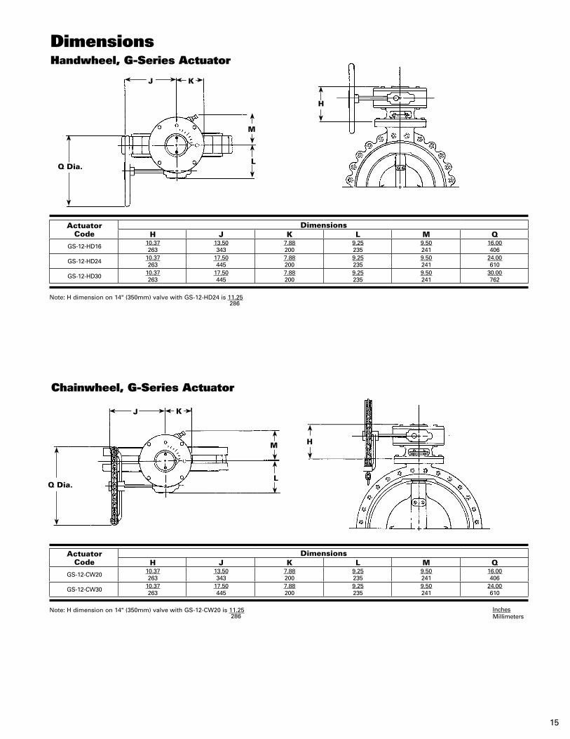
DimensionsHandwheel, G-Series Actuator
Chainwheel, G-Series Actuator
Note: H dimension on 14" (350mm) valve with GS-12-CW20 is 11.25 286
Note: H dimension on 14" (350mm) valve with GS-12-HD24 is 11.25 286
H
H
Q Dia.
J K
M
L
Q Dia.
J K
M
L
ActuatorCode
DimensionsH J K L M Q
GS-12-HD16 10.37263
13.50343
7.88200
9.25235
9.50241
16.00406
GS-12-HD24 10.37263
17.50445
7.88200
9.25235
9.50241
24.00610
GS-12-HD30 10.37263
17.50445
7.88200
9.25235
9.50241
30.00762
ActuatorCode
DimensionsH J K L M Q
GS-12-CW20 10.37263
13.50343
7.88200
9.25235
9.50241
16.00406
GS-12-CW30 10.37263
17.50445
7.88200
9.25235
9.50241
24.00610

DeZURIK, Inc. reserves the right to incorporate our latest design and material changes without notice or obligation. Design features, materials of construction and dimensional data, as described in this bulletin, are provided for your information only
and should not be relied upon unless confirmed in writing by DeZURIK, Inc. Certified drawings are available upon request.
Printed in the U.S.A.
250 Riverside Ave. N. Sartell, Minnesota 56377 • Phone: 320-259-2000 • Fax: 320-259-2227
For information about our worldwide locations, approvals, certifications and local representative:Web Site: www.dezurik.com E-Mail: [email protected]
Sales and Service