Embed Size (px)
Citation preview

DEVICENET OPTION CARD
SOPCG11SDEV
FOR GP10 & VG10
INSTRUCTION MANUAL
Saftronics, Inc.
5580 Enterprise Pkwy., Ft. Myers, Fl 33905
Telephone: (239) 693-7200
Fax: (239) 693-2431 PART NUMBER 027-2150
www.saftronics.com REV June 2002
efesotomasyon.com - Control Techniques,emerson,saftronics -ac drive-servo motor

DeviceNet Option Cardfor GP10 and VG10
2 JUNE 2002
Revision Notes
Date: Document: Notes:99.12.1300.03.30----01.01.2401.03.0601.03.1901.03.3001.04.2601.07.1801.09.1301.09.1802.02.01
02.03.18
Revision 1.00Revision 1.01Revision 1.02Revision 1.03Revision 1.04Revision 1.05Revision 1.06Revision 1.07Revision 1.08Revision 1.09Revision 1.10Revision 1.11Revision 1.12
Revision 1.13
Created.Corrections.Corrections.Corrections.Corrections, Chapter 4.Corrections, Chapters 4.4 and 4.8.Corrections, Chapter 4.5.New Software (1.20), Corrections Chapter 4.4.Added Instance in Chapter 4.9.Modification of the scaleparameters in 4.8.Notetext added in 4.8.Correction in 4.5.Changed Produced/Consumed connection paths inConnection Object.Update according to comments
Related documents
Document AuthorDeviceNet Specification Vol 1 & Vol Rev 2.02 ODVAGP10 Instruction Manual P/N 027-GP1001VG10 Instruction Manual P/N 027-VG1001
Saftronics
PrefaceThe data and illustrations found in this document are not binding. We reserve the right to modify our products in line with ourpolicy of continuous product development. The information in this appendix is subject to change without notice and should notbe considered as a commitment by SAFTRONICS, INC.HMS INDUSTRIAL NETWORKS AB assumes no responsibility for any errors that may appear in this document.
The product and technology described in this document is patent pending in the following countries:USA, Canada, Japan, Belgium, Denmark, Finland, France, Greece, Ireland, Italy, Luxemburg, Monaco, Netherlands, Portugal,Switzerland, Lichtenstein, Spain, United Kingdom, Sweden, Germany and Austria.
ANYBUS is a registered trademark of HMS INDUSTRIAL NETWORKS AB.All other trademarks are the property of their respective holders.
efesotomasyon.com - Control Techniques,emerson,saftronics -ac drive-servo motor
DeviceNet Option Cardfor GP10 and VG10
JUNE 2002 3
Table of Contents
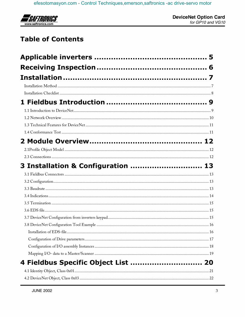
Applicable inverters ............................................... 5
Receiving Inspection.............................................. 6
Installation............................................................ 7Installation Method ......................................................................................................................................................... 7
Installation Checklist ....................................................................................................................................................... 8
1 Fieldbus Introduction .......................................... 91.1 Introduction to DeviceNet......................................................................................................................................... 9
1.2 Network Overview................................................................................................................................................... 10
1.3 Technical Features for DeviceNet ........................................................................................................................... 11
1.4 Conformance Test ................................................................................................................................................... 11
2 Module Overview............................................... 122.1Profile Object Model ................................................................................................................................................ 12
2.3 Connections ............................................................................................................................................................. 12
3 Installation & Configuration .............................. 133.1 Fieldbus Connectors ................................................................................................................................................ 13
3.2 Configuration........................................................................................................................................................... 13
3.3 Baudrate ................................................................................................................................................................... 13
3.4 Indications................................................................................................................................................................ 14
3.5 Termination ............................................................................................................................................................. 15
3.6 EDS file.................................................................................................................................................................... 15
3.7 DeviceNet Configuration from inverters keypad..................................................................................................... 15
3.8 DeviceNet Configuration Tool Example ................................................................................................................ 16
Installation of EDS-file.............................................................................................................................................. 16
Configuration of Drive parameters............................................................................................................................ 17
Configuration of I/O assembly Instances .................................................................................................................. 18
Mapping I/O- data to a Master/Scanner .................................................................................................................. 19
4 Fieldbus Specific Object List .............................. 204.1 Identity Object, Class 0x01...................................................................................................................................... 21
4.2 DeviceNet Object, Class 0x03 ................................................................................................................................. 22
efesotomasyon.com - Control Techniques,emerson,saftronics -ac drive-servo motor

DeviceNet Option Cardfor GP10 and VG10
4 JUNE 2002
4.3 Assembly Object, Class 0x04................................................................................................................................... 23
4.4 DeviceNet Connection Object (0x05) ..................................................................................................................... 27
4.5 Acknowledge Handler Object (0x2B) ..................................................................................................................... 30
4.6 Motor Data Object (0x28)....................................................................................................................................... 31
4.7 Control Supervisor Object (0x29)............................................................................................................................ 32
Run/Stop Event Matrix ............................................................................................................................................. 33
State transition diagram............................................................................................................................................. 33
4.8 AC/DC-Drive Object (0x2A) ................................................................................................................................. 34
4.9 Saftronics VendorSpecific Object (0x64)................................................................................................................. 35
Command data............................................................................................................................................................... 36
Operation command data .............................................................................................................................................. 36
Function data ................................................................................................................................................................. 38
Parameter data format.................................................................................................................................................... 41
Data format specification ............................................................................................................................................... 47
Action at communication error...................................................................................................................................... 51
efesotomasyon.com - Control Techniques,emerson,saftronics -ac drive-servo motor

DeviceNet Option Cardfor GP10 and VG10
JUNE 2002 5
Applicable inverters
Item Description
Inverter type GP10 and VG10Compatible InverterModel number
The last two digits of the model number should be B1 or laterExample: 6KG1123X1B1
Minimum inverterROM version number
up to 22 kW(30HP) EN, Japanese standard, JE,CN, UX and Saftronicsversion
S08000 and after(It is impossible to use version priorto S08000 inverter.)
30 kW(40HP) andabove
EN, Japanese standard,JN, JE, AN, CN, UXand Saftronics version
H08004 and after(It is impossible to use versions ofH00000 to H08003.)
NOTE:This product can only be used for Inverters with ROM version numbers greater than or equal to the versionsshown above.And in the case of installing this option in the GP10 / VG10 inverter that is a Japanese standard, JN, JE or CNversion, please contact Saftronics or its distributors.
Check the ROM number of your Inverter as follows using the inverter keypad.a. Check that the Inverter Operation monitor (Operation mode) screen is displayed.b. Press the [PRG] key of the Inverter once.c. Select the "5. MAINTENANC" with the cursor and press the [FUNC/DATA] key.d. Press the down cursor key to increment the display at the MAINTENANC screen.
Finally, the ROM number is shown in the maintenance information, as indicated by the display"INV=Hxxxxx or Sxxxxx".
The maintenance and inspection items are similar to the Inverter unit, for detail refer to the Inverter InstructionManual.
efesotomasyon.com - Control Techniques,emerson,saftronics -ac drive-servo motor

DeviceNet Option Cardfor GP10 and VG10
6 JUNE 2002
Receiving Inspection
Confirm the following items upon a receipt.
1) The model number matches your purchase order? Check the model number printed on the circuit board.
Model : SOPC - G11S - DEV
OPTION TYPEDEV -> DeviceNet INTERFACE OPTION
INVERTER TYPEG11S -P11S ->
> Saftronics VG10 Saftronics GP10
2) Inspection for damage during transportation. Report damage to transportation carrier.
efesotomasyon.com - Control Techniques,emerson,saftronics -ac drive-servo motor

DeviceNet Option Cardfor GP10 and VG10
JUNE 2002 7
Installation
Installation Method
Please follow the installation procedure described as follows. Please install or detach the option after turning off the inputpower supply of the inverter and confirming the charge lamp (CHARGE or CRG) is gone out.The shape, the dimensions and the position of the charge lamp of the inverter are different by each capacity.
Inverter unit
Secure the keypad panel to the option unit with two screws at b.
Step4
Step1
Step2
Step3
Loosen two screws(M4) at a and remove the top cover. Loosen two screws(M3) at b and detach thekeypad panel. (For the 30kW[40HP] and above inverters, the keypad panel can be detached if the frontcover is removed and the screws loosened at b.)
Connect the ground cable to the PE terminal of the option unit.
Reassemble the top cover, push-in the option unit and secure it with two screws(M3) at c.
PE Line
Option unitkeypad
Step2 to 4Step1
Inverter unit
Top cover
keypad
Charge lamp
efesotomasyon.com - Control Techniques,emerson,saftronics -ac drive-servo motor

DeviceNet Option Cardfor GP10 and VG10
8 JUNE 2002
Installation ChecklistInstallation Checklist
After installation and wiring, check the following items.
[1] The wiring is correct.[2] No loose wires or screws remain inside the Inverter.[3] The screws and terminals are all tight.[4] There are no loose threads of wires at terminals that may contact other terminals.[5] The switch positions on the Anybus-S module, JP6 on the conversion-board are suitable for the use purpose.
(Do not change the JP4 on the conversion-board!)[6] Inverter parameters such as H30, o27, o28, o31 to o40, are set correctly. (H30: Link Active/Inactive, o27
and o28: for RAS, o31 to o40: for I/O assembly instances)
efesotomasyon.com - Control Techniques,emerson,saftronics -ac drive-servo motor

DeviceNet Option Cardfor GP10 and VG10
JUNE 2002 9
1 Fieldbus IntroductionThis section provides information about the DeviceNet organisation and network.
1.1 Introduction to DeviceNetDeviceNet is used for industrial automation, normally for the control of valves, sensors and I/O units and otherautomation equipment. The DeviceNet communication link is based on a broadcast-oriented, communicationsprotocol, the Controller Area Network (CAN). This protocol has I/O response and high reliability even fordemanding applications,e.g., control of brakes.
DeviceNet has an user organisation, the Open DeviceNet Vendor Association (ODVA), that assists members ofmatters concerning DeviceNet. HMS is a member of ODVA and also represented as a member of theDeviceNet System Architecture SIG.
For further information, please contact ODVA on e-mail: [email protected] or at address:ODVA - William H. (Bill) Moss, Executive Director20423 State Road 7 - Suite 499 - Boca Raton, FL 33498 USA(1) 954 340-5412 or (1) 561 477-7966 Phone(1) 954 340-5413 or (1) 561 477-6621 Fax
efesotomasyon.com - Control Techniques,emerson,saftronics -ac drive-servo motor

DeviceNet Option Cardfor GP10 and VG10
10 JUNE 2002
1.2 Network OverviewThe media for the fieldbus is a shielded copper cable composed of one twisted pair and two cables for theexternal power supply. The baudrate can be changed between 125k, 250k and 500kbit/s, this can be done inthree different ways. First is simply by the DIP switch, second via the fieldbus and third is autobaudrate setting.
Several different DeviceNet Scanners are available on the market, both for PLC-systems and PC computers.
Picture 1: DeviceNet overwiew
SMC
Allen-Bradley
Drive
Sensor
Bar Code ScannerDevice Configuration
Other Devices
Motor Controller
Controller
DeviceNet
Pushbutton Cluster Motor
Starter
Input/OutputDevices
efesotomasyon.com - Control Techniques,emerson,saftronics -ac drive-servo motor
DeviceNet Option Cardfor GP10 and VG10
JUNE 2002 11
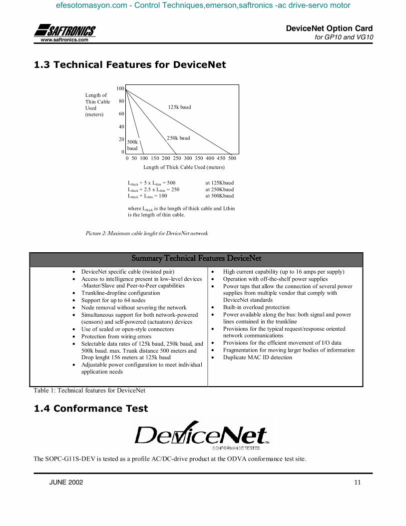
1.3 Technical Features for DeviceNet
Length ofThin CableUsed(meters)
100
80
60
40
20
00 50 100 150 200 250 300 350 400 450 500
125k baud
250k baud500kbaud
Length of Thick Cable Used (meters)
Lthick + 5 x Lthin = 500 at 125KbaudLthick + 2.5 x Lthin = 250 at 250KbaudLthick + Lthin = 100 at 500Kbaud
where Lthick is the length of thick cable and Lthinis the length of thin cable.
Picture 2: Maximum cable lenght for DeviceNet network
Summary Technical Features DeviceNetSummary Technical Features DeviceNetSummary Technical Features DeviceNetSummary Technical Features DeviceNet
• DeviceNet specific cable (twisted pair)• Access to intelligence present in low-level devices
-Master/Slave and Peer-to-Peer capabilities• Trunkline-dropline configuration• Support for up to 64 nodes• Node removal without severing the network• Simultaneous support for both network-powered
(sensors) and self-powered (actuators) devices• Use of sealed or open-style connectors• Protection from wiring errors• Selectable data rates of 125k baud, 250k baud, and
500k baud. max. Trunk distance 500 meters andDrop lenght 156 meters at 125k baud
• Adjustable power configuration to meet individualapplication needs
• High current capability (up to 16 amps per supply)• Operation with off-the-shelf power supplies• Power taps that allow the connection of several power
supplies from multiple vendor that comply withDeviceNet standards
• Built-in overload protection• Power available along the bus: both signal and power
lines contained in the trunkline• Provisions for the typical request/response oriented
network communications• Provisions for the efficient movement of I/O data• Fragmentation for moving larger bodies of information• Duplicate MAC ID detection
Table 1: Technical features for DeviceNet
1.4 Conformance Test
The SOPC-G11S-DEV is tested as a profile AC/DC-drive product at the ODVA conformance test site.
efesotomasyon.com - Control Techniques,emerson,saftronics -ac drive-servo motor

DeviceNet Option Cardfor GP10 and VG10
12 JUNE 2002
2 Module OverviewThis section provides an overview over the AnyBus-S DeviceNet module.The SOPC-G11S-DEV is implemented according to the ODVA specification for a AC/DC-Drive Profile (profile no 2). It isacting as a ”group two server” on the DeviceNet network.
2.1Profile Object Model
The interface from the fieldbus against the SOPC-G11S-DEV is based on the standard DeviceNet objects, three profile objectsand one vendor specific object. Object Model
2.3 ConnectionsConnections supported:
5 UCMM Explicit Server1 Master/Slave Explicit Server1 Master/Slave Polled I/O Server1 Master/Slave Change of state I/O
Explicit
Message Router
Identity
Assembly
Connection
Application Fuji vendorspecific
Acknowledge Handler
Assembly I/O
DeviceNet
OutputInput
ControlSupervisor
Motor Data
AC/DC Drive
efesotomasyon.com - Control Techniques,emerson,saftronics -ac drive-servo motor

DeviceNet Option Cardfor GP10 and VG10
JUNE 2002 13
3 Installation & Configuration
3.1 Fieldbus ConnectorsThe table below shows the pin function of the fieldbus connectors.
BUS connectorPluggableconnector
ScrewTerminal
Description
1 1 V-2 2 CAN_L3 3 SHIELD4 4 CAN_H5 5 V+
Description of fieldbus connectors
3.2 ConfigurationMacId (= Node address) and BaudRate are configured by a DipSwitch at the front of the module. The range for MacID isbetween 0-63 and BaudRate is between 0 and 2 (0=125kb, 1=250kb, 2=500kb).
3.3 BaudrateThere are three different baudrates for DeviceNet; 125k, 250k, 500kbit/s. Choose one of them by setting the DIP switch beforeconfiguring.
1 2 3 87654
OFF
ON
Baud Rate MAC ID
BD0 = 2BD1 = 1
AD0 = 8AD1 = 7AD2 = 6AD3 = 5AD4 = 4AD5 = 3
Address DIP 3-8
0 000000
... ...
2 000010
1 000001
62 111110
3 000011
63 111111
Baudratebit/sec DIP 1-2
Reserved 11
250k 01
125k 00
500k 10
efesotomasyon.com - Control Techniques,emerson,saftronics -ac drive-servo motor
DeviceNet Option Cardfor GP10 and VG10
14 JUNE 2002
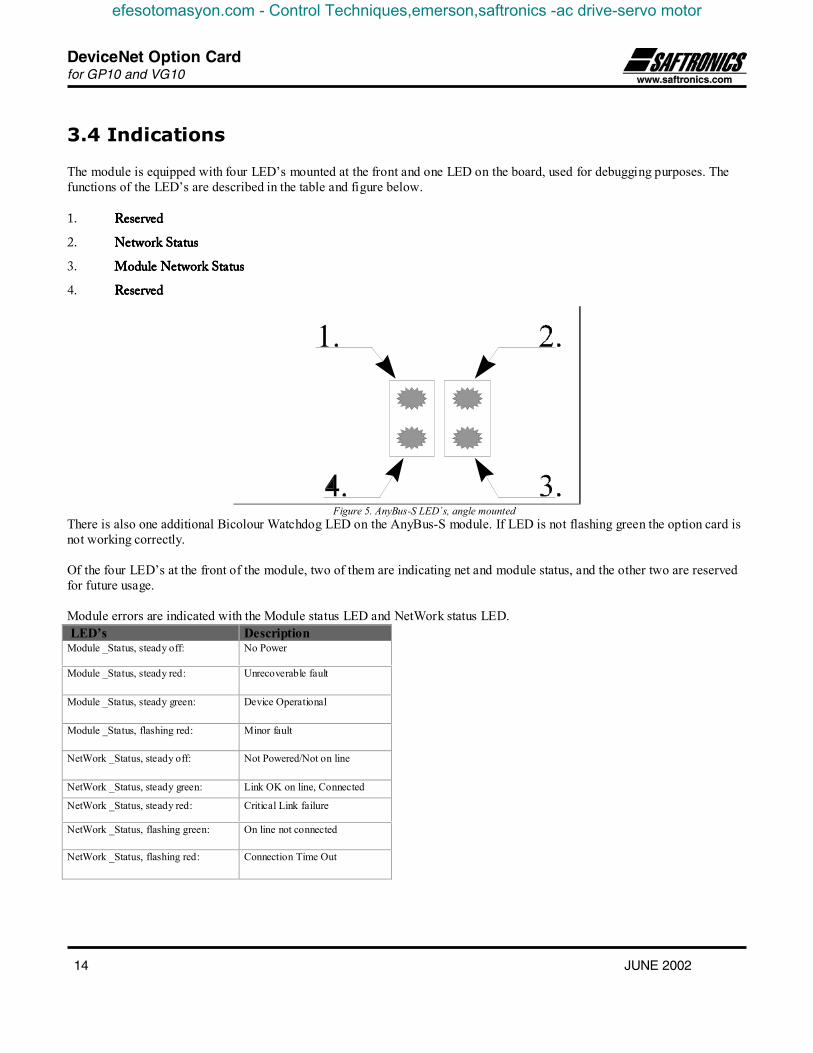
3.4 Indications
The module is equipped with four LED’s mounted at the front and one LED on the board, used for debugging purposes. Thefunctions of the LED’s are described in the table and figure below.
1. ReservedReservedReservedReserved
2. Network StatusNetwork StatusNetwork StatusNetwork Status
3. Module Network StatusModule Network StatusModule Network StatusModule Network Status
4. ReservedReservedReservedReserved
Figure 5. AnyBus-S LED´s, angle mountedThere is also one additional Bicolour Watchdog LED on the AnyBus-S module. If LED is not flashing green the option card isnot working correctly.
Of the four LED’s at the front of the module, two of them are indicating net and module status, and the other two are reservedfor future usage.
Module errors are indicated with the Module status LED and NetWork status LED. LED’s DescriptionModule _Status, steady off: No Power
Module _Status, steady red: Unrecoverable fault
Module _Status, steady green: Device Operational
Module _Status, flashing red: Minor fault
NetWork _Status, steady off: Not Powered/Not on line
NetWork _Status, steady green: Link OK on line, Connected
NetWork _Status, steady red: Critical Link failure
NetWork _Status, flashing green: On line not connected
NetWork _Status, flashing red: Connection Time Out
efesotomasyon.com - Control Techniques,emerson,saftronics -ac drive-servo motor

DeviceNet Option Cardfor GP10 and VG10
JUNE 2002 15
3.5 TerminationTermination of the fieldbus requires a terminating resistor at each end of the fieldbus. These resistors should have a value of121 Ω.
3.6 EDS fileEach device in a DeviceNet network is associated with an EDS file, containing all necessary information about the device. Thenetwork configuration tool uses this file during configuration of the network.
3.7 DeviceNet Configuration from inverters keypadThe SOPC-G11S-DEV provides a simple configuration interface through the keypad. The bus configuration parameters useparameters designated for the Analog/Digital I/O option. Since the I/O option cannot be used with the fieldbus option, theseparameters can be shared. The keypad supports the most important parameters can be configured this way. For more complexconfgurations a configuration tool is needed.
Bus ConfigurationParameter
Description Default Value Possible values
o27 DN faultmode, defines action when thenetwork is malfunctioning. For furtherinformation see Control Supervisor Object.
0 0,1,2,3
o31 Output Assembly Instance, defines what datathat will be used for the I/O connection
0 (=21) 20,21,100,102
o32 Input Assembly Instance defines what datathat will be used for the I/O connection
0 (=71) 70,71, 101,103
o33 User Defined Output I/O Parameter 1see assembly object.
0 0-255
o34 User Defined Output I/O Parameter 2see assembly object.
0 0-255
o35 User Defined Output I/O Parameter 3see assembly object.
0 0-255
o36 User Defined Output I/O Parameter 4see assembly object.
0 0-255
o37 User Defined Input I/O Parameter 1see assembly object.
0 0-255
o38 User Defined Input I/O Parameter 2see assembly object.
0 0-255
o39 User Defined Input I/O Parameter 3see assembly object. 0
0-255
o40 User Defined Input I/O Parameter 4see assembly object.
0 0-255
efesotomasyon.com - Control Techniques,emerson,saftronics -ac drive-servo motor

DeviceNet Option Cardfor GP10 and VG10
16 JUNE 2002
3.8 DeviceNet Configuration Tool ExampleThe SOPC-G11S-DEV can be configured with all configuration tools on the market that are DeviceNet compliant. The mostcommon tool is the RSNetworx from Rockwell; this is the one that is used in this example.
Installation of EDS-fileThe first time you start up the configuration tool you must install an EDS file for the SOPC-G11S-DEV. This file containsinformation about the internal structure and I/O configuration of the device. By choosing Tools ->EDS Wizard in the menu ofRSNetWorx the dialog shown below will appear, You must enter the location of the EDS file here. After this RSNetWorx willinstall all the information from the EDS file into its database.
efesotomasyon.com - Control Techniques,emerson,saftronics -ac drive-servo motor

DeviceNet Option Cardfor GP10 and VG10
JUNE 2002 17
Configuration of Drive parametersIf you make a Network Brose a picture of a motor will appear on the screen. Double-click on the picture and the dialog belowwill be shown. In this window you can edit and monitor all the drive specific parameters present in the drive. The deviceparameters appear in the list arranged in numerical order by parameter number. When the lock icon precedes the number, theparameter is read only.
efesotomasyon.com - Control Techniques,emerson,saftronics -ac drive-servo motor

DeviceNet Option Cardfor GP10 and VG10
18 JUNE 2002
Configuration of I/O assembly InstancesThere are two different ways of configuring the I/O assembly instances, one is by the keypad and the other one is explainedhere. Parameters 233 and 234 in the EDS file are used to choose the actual I/O assemblies. The default value is 21 for theoutput data and 71 for the input data. If those values are not valid the default values will be used instead. For more informationabout the I/O assemblies please see the Assembly object section.
efesotomasyon.com - Control Techniques,emerson,saftronics -ac drive-servo motor

DeviceNet Option Cardfor GP10 and VG10
JUNE 2002 19
Mapping I/O- data to a Master/ScannerAfter the configuration of the SOPC-G11S-DEV itself you will have to configure a connection to a master. This exampleshows how to configure one specific master. All scanners are configured in different ways but this configuration can be usedfor all Rockwell scanners and for the AnybBus scanner.Double-click on the scanners Icon and select “scanlist” and the dialog shown below will appear. Drag the icon from availabledevices to the scanlist.
Click on the button “Edit I/O Parameters ” and the following dialog will be shown.Depending on what configuration you have of the I/O assemblies you have to enter the input and output sizes.Also you must select what type of I/O connection you want the Master to use. The default setting is 4 bytes in/out polled data
After this is done you must configure Offsets and data mapping into the scanners scan list, this is very different for differentscanners. Please see the scanners documentation.
efesotomasyon.com - Control Techniques,emerson,saftronics -ac drive-servo motor

DeviceNet Option Cardfor GP10 and VG10
20 JUNE 2002
4 Fieldbus Specific Object ListThe following objects are included in the module:
DeviceNet objects
• Identity object Class 0x01
• Message router Class 0x02
• DeviceNet object Class 0x03
• Assembly object Class 0x04
• Connection object Class 0x05
• Acknowledge Handler object Class 0x2B
Profile specific objects
• AC/DC object Class 0x2A
• Control Super visor object Class 0x29
• Motor data object Class 0x28
Vendor specific objects
• Saftronics parameter Object Class 0x64
efesotomasyon.com - Control Techniques,emerson,saftronics -ac drive-servo motor

DeviceNet Option Cardfor GP10 and VG10
JUNE 2002 21
4.1 Identity Object, Class 0x01
Class Attributes (0)# Attribute
NameServices Description Data
Type1 Revis ion Get_Attr ibute_Single Revis ion of the Identity Object Class Definition
upon which the implementation is basedUINT
Instance Attributes (1)# Attribute
NameServices Description Default,
Minimum,Maximum
DataType
1 Vendor Id Get Identification of each vender by number 90,90,90
UINT
2 Device Type Get Indication of the general type of product 2,2,2
UINT
3 Product Code Get This is a code assigned by the vendor todescribe the device
G11-> 18,E11-> 19,VG7-> 20
UINT
4 Revis ion Get Revis ion of the item the Identity Objectrepresents
1,38,1,38,1,38
Array of :USINTUSINT
5 Status Get Summary Status of the Device 0,0,255
WORD
6 Serial Number Get Serial Number of the device N/A,N/A,N/A
UDINT
7 Product Name Get Human readable identification " OPC-G11S-DEV ",N/A,N/A.
SHORT_STRING
9 Config.Consist.Value
Get Contents identify configuration of device N/A,N/A,N/A
UINT
efesotomasyon.com - Control Techniques,emerson,saftronics -ac drive-servo motor

DeviceNet Option Cardfor GP10 and VG10
22 JUNE 2002
4.2 Message Router Object, Class 0x02
Class Attributes (0)# Attribute
NameServices Description Data
Type1 Revis ion Get_Attr ibute_Single Revis ion of the Message Router Object Class
Definition upon which the implementation is basedUINT
4.2 DeviceNet Object, Class 0x03
Class Attributes(0)# Attribute
NameServices Description Data
Type1 Revis ion Get_Attr ibute_Single Revis ion of the DeviceNet Object Class Definition
upon which the implementation is basedUINT
Instance Attributes (1)# Attribute
NameServices Description Default,
Minimum,Maximum
DataType
1 MAC ID Get_Attr ibute_Single Node Address. DIPSWITCH,0,63
USINT
2 Baud Rate Get_Attr ibute_Single The baud rate of thedevice
DIPSWITCH,0,2
USINT
5 AllocationInformation
Get_Attr ibute_Single Allocation ChoiceMaster's Mac ID
N/A,N/A,N/A
Struct of:BYTEUSINT
efesotomasyon.com - Control Techniques,emerson,saftronics -ac drive-servo motor

DeviceNet Option Cardfor GP10 and VG10
JUNE 2002 23
4.3 Assembly Object, Class 0x04Instance Type Name
20 Required Output Basic Speed Control Output
21 Optional Output Extended Speed Control Output
100 Optional Output Saftronics Drive Assembly Output
102 Optional Output User Defined Assembly
70 Required Input Basic Speed Control Input
71 Optional Input Extended Speed Control Input
101 Optional Input Saftronics Drive Assembly Input
103 Optional Input User Defined Assembly
Instance Byte Bit7 Bit6 Bit5 Bit4 Bit3 Bit2 Bit1 Bit00 Fault Reset Run Forward
1
2 Speed Reference (Low Byte)
20
3 Speed Reference (High Byte)
Instance Byte Bit7 Bit6 Bit5 Bit4 Bit3 Bit2 Bit1 Bit00 NetRef NetCtrl Fault Reset Run Reverse Run Forward
1
2 Speed Reference (Low Byte)
21
3 Speed Reference (High Byte)
Explanation of 20 and 21 I/O Assembly Data Attribute ComponentsName Class Instance Attribute
Name Number Type G11 equivalentOutput Data
RunFwd ControlSuperv
1 Run1 3 BOOL S06 bit 0 = 1
RunRev ControlSuperv
1 Run2 4 BOOL S06 bit 1 = 1
Reset ControlSuperv
1 FaultRst 12 BOOL
NetCtrl ControlSuperv
1 NetCtrl 5 BOOL
NetRef AC/DC Drive 1 NetRef 4 BOOL
If NetCtrl = 0 and Net Ref =0 then H30 = 0If NetCtrl = 0 and Net Ref = 1 then H30 = 1If NetCtrl = 1 and Net Ref =0 then H30 = 2If NetCtrl = 1 and Net Ref = 1 then H30 = 3
Speed Ref AC/DC Drive 1 SpeedRef 8 INT Units RPM /2SpeedScale
efesotomasyon.com - Control Techniques,emerson,saftronics -ac drive-servo motor

DeviceNet Option Cardfor GP10 and VG10
24 JUNE 2002
Instance Byte Bit7 Bit6 Bit5 Bit4 Bit3 Bit2 Bit1 Bit0
0 RunningForward
Faulted
12 Speed Actual (Low Byte)
70
3 Speed Actual (High Byte)
Instance Byte Bit7 Bit6 Bit5 Bit4 Bit3 Bit2 Bit1 Bit0
0 AtReference
Ref FromNet
Ctrl FromNet
Ready RunningReverse
RunningForward
Warning Faulted
1 Drive State2 Speed Actual (Low Byte)
71
3 Speed Actual (High Byte)
Explanation of 70 and 71 I/O Assembly Data Attribute ComponentsName Class Instance Attribute
Name Number Type G11 equivalentFaulted Control
Superv1 Faulted 10 BOOL M14 bit 11 = 1
Warning ControlSuperv
1 Warning 11 BOOL
RunningForward
ControlSuperv
1 Running1 7 BOOL M14 bit 0 = 1
RunningReverse
ControlSuperv
1 Running2 8 BOOL M14 bit 1 =1
Ready ControlSuperv
1 Ready 9 BOOL M14 bit 11 = 0, 5 = 1 and 3 =0
CtlFromNet ControlSuperv
1 CtlFromNet 15 BOOL H30 = 2 or 3 and M14 bit12 = 1
DriveState ControlSuperv
1 DriveState 6 USINT 1=Start/up 2=Not_ready 3=Ready4=Enabled 5=Stopping 6= FaultStop7=Faulted
RefFromNet AC/DCDrive
1 RefFromNet 29 BOOL H30 = 1 or 3 M14 bit 12 = 1
At Ref AC/DCDrive
1 At Ref 3 BOOL Frequency arrival
Speed Act AC/DCDrive
1 Speed Act 7 INT Units RPM/2SpeedScale M01.
efesotomasyon.com - Control Techniques,emerson,saftronics -ac drive-servo motor

DeviceNet Option Cardfor GP10 and VG10
JUNE 2002 25
Instance Byte Bit7 Bit6 Bit5 Bit4 Bit3 Bit2 Bit1 Bit0
0 X6 X5 X4 X3 X2 X1 REV FWD
1 RST - - - - X9 X8 X7
3 Frequency Command (Low Byte) Same as S01
100
4 Frequency Command (High Byte) Same as S01
Explanation of 100 I/O Assembly Data Attribute Components:
FWD: Forward rotation commandREV: Reverse rotation commandX1..X9 : Multi-function commandRST: Alarm reset command
From 0 to 1 and 1 to 0, minimuminterval = 20 mS
Instance Byte Bit7 Bit6 Bit5 Bit4 Bit3 Bit2 Bit1 Bit0
0 VL TL NUV BRK INT EXT REV FWD
1 BUSY ERR WR RL ALM DEC ACC IL
3 Frequency Output (Low Byte) Same as M06
101
4 Frequency Output (High Byte) Same as M06
Explanation of 101 I/O Assembly Data Attribute Components:
FWD: In forward operation DEC: In decelerationREV: In reverse operation ALM: AlarmEXT: In DC braking (or in pre-excitation) RL: Run command or Frequency command
is valid from DeviceNet.INT: Inverter Base Off WR: Parameter writing rightBRK: In braking 0: Keypad panel or RS485NUV: DC link voltage is establishment
(Undervoltage condition at 0) 1: Link (option)
TL: In torque limiting ERR Parameter Access errorVL: In voltage limiting BUSY In writing parameterIL: In current limitingACC: In acceleration
efesotomasyon.com - Control Techniques,emerson,saftronics -ac drive-servo motor
DeviceNet Option Cardfor GP10 and VG10
26 JUNE 2002
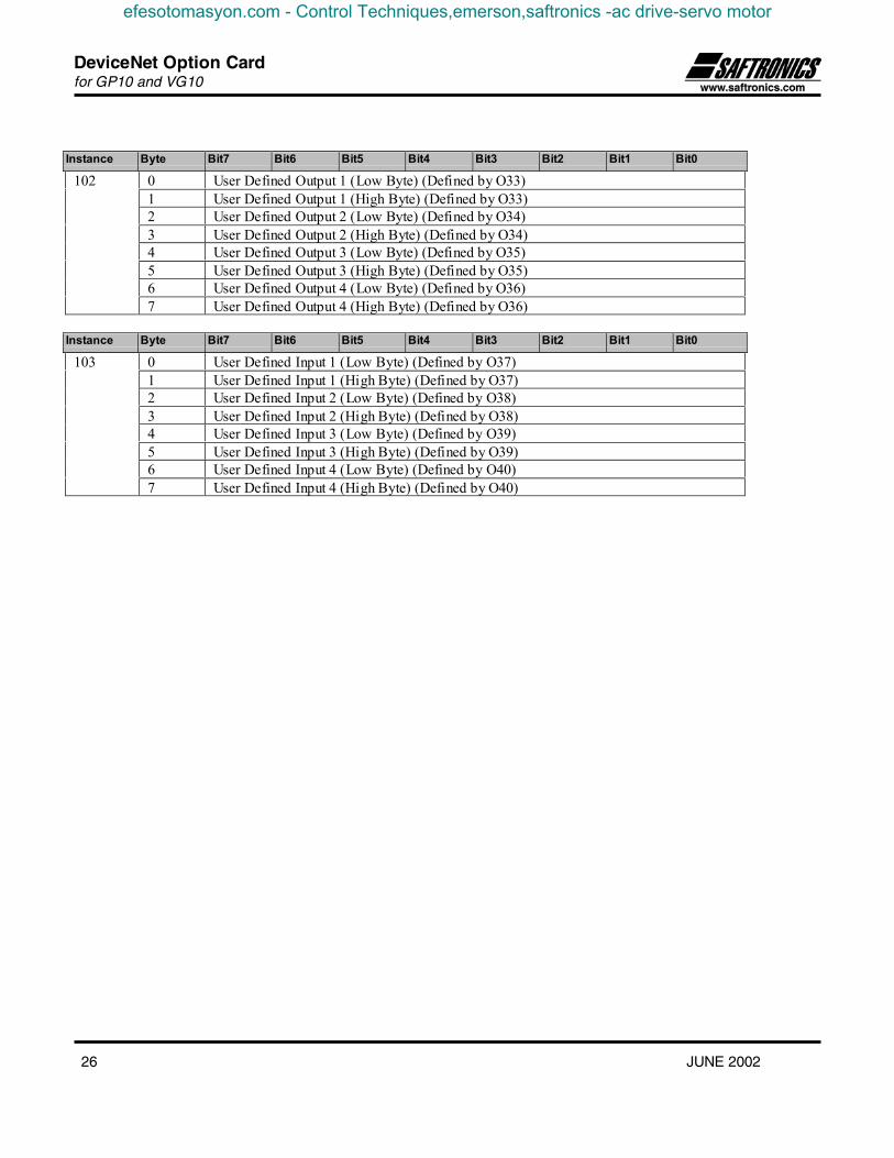
Instance Byte Bit7 Bit6 Bit5 Bit4 Bit3 Bit2 Bit1 Bit0
0 User Defined Output 1 (Low Byte) (Defined by O33)1 User Defined Output 1 (High Byte) (Defined by O33)2 User Defined Output 2 (Low Byte) (Defined by O34)3 User Defined Output 2 (High Byte) (Defined by O34)4 User Defined Output 3 (Low Byte) (Defined by O35)5 User Defined Output 3 (High Byte) (Defined by O35)6 User Defined Output 4 (Low Byte) (Defined by O36)
102
7 User Defined Output 4 (High Byte) (Defined by O36)
Instance Byte Bit7 Bit6 Bit5 Bit4 Bit3 Bit2 Bit1 Bit0
0 User Defined Input 1 (Low Byte) (Defined by O37)1 User Defined Input 1 (High Byte) (Defined by O37)2 User Defined Input 2 (Low Byte) (Defined by O38)3 User Defined Input 2 (High Byte) (Defined by O38)4 User Defined Input 3 (Low Byte) (Defined by O39)5 User Defined Input 3 (High Byte) (Defined by O39)6 User Defined Input 4 (Low Byte) (Defined by O40)
103
7 User Defined Input 4 (High Byte) (Defined by O40)
efesotomasyon.com - Control Techniques,emerson,saftronics -ac drive-servo motor

DeviceNet Option Cardfor GP10 and VG10
JUNE 2002 27
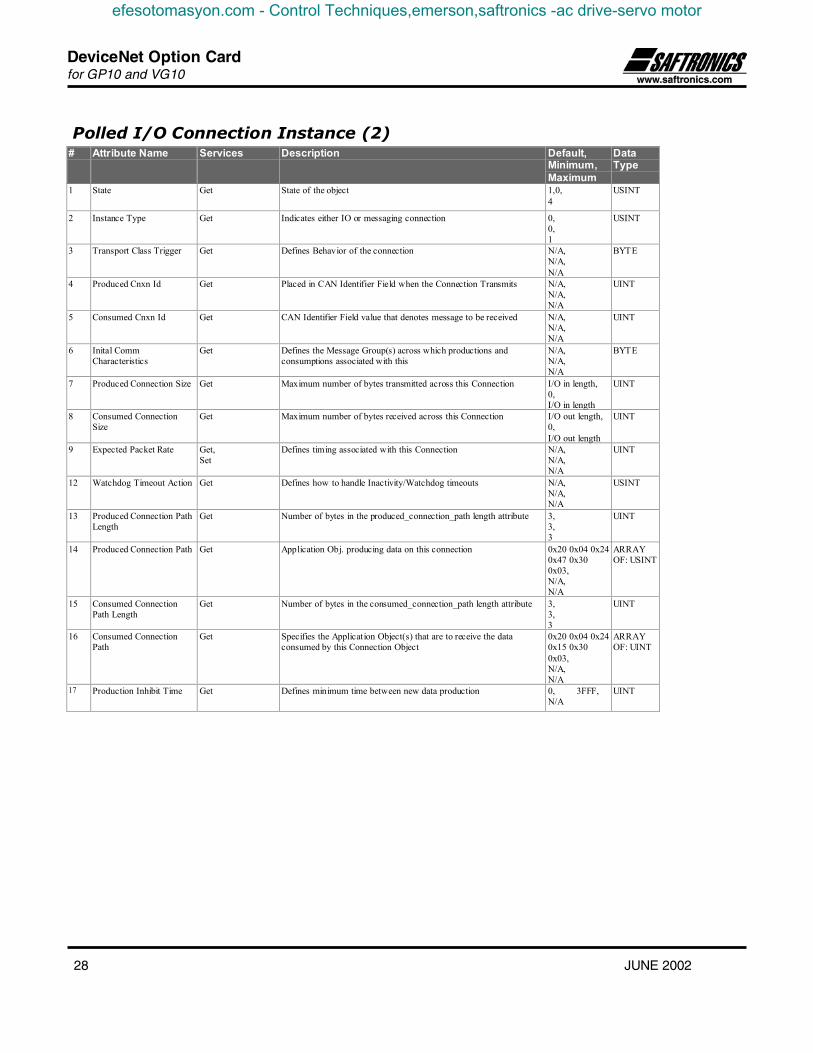
4.4 DeviceNet Connection Object (0x05)
Class Attributes (0)# Attribute
NameServices Description Data
Type1 Revis ion Get_Attr ibute_Single Revis ion of the Connection Object Class Definition
upon which the implementation is basedUINT
Explicit Connection Instance (1)# Attribute Name Services Description Default,
Minimum,Maximum
DataType
1 State Get State of the object 1,0,5
USINT
2 Instance Type Get Indicates either IO or messaging connection 0,0,0
USINT
3 Transport Class Trigger Get Defines Behavior of the connection 0x83,0x83,0x83
BYTE
4 Produced Cnxn Id Get Placed in CAN Identifier Field when the Connection Transmits N/A,N/A,N/A
UINT
5 Consumed Cnxn Id Get CAN Identifier Field value that denotes message to be received N/A,N/A,N/A
UINT
6 Inital CommCharacteristics
Get Defines the Message Group(s) across which productions andconsumptions associated with this
N/A,N/A,N/A
BYTE
7 Produced Connection Size Get Maximum number of bytes transmitted across this Connection 256,256,256
UINT
8 Consumed ConnectionSize
Get Maximum number of bytes received across this Connection 256,256,256
UINT
9 Expected Packet Rate Get, Set Defines timing associated with this Connection N/A,N/A,N/A
UINT
12 Watchdog Timeout Action Get, Set Defines how to handle Inactivity/Watchdog timeouts N/A,N/A,N/A
USINT
13 Produced Connection PathLength
Get Number of bytes in the produced_connection_path length attribute 256,256,256
UINT
14 Produced Connection Path Get Application Obj. producing data on this connection NULL,NULL,NULL
ARRAYOF:USINT
15 Consumed ConnectionPath Length
Get Number of bytes in the consumed_connection_path length attribute 256,256,256.
UINT
16 Consumed ConnectionPath
Get Specifies the Application Object(s) that are to receive the dataconsumed by this Connection Object
NULL,NULL,NULL
ARRAYOF: 01UINT
17 Production Inhibit Time Get Defines minimum time between new data production 0,0,0 UINT
efesotomasyon.com - Control Techniques,emerson,saftronics -ac drive-servo motor
DeviceNet Option Cardfor GP10 and VG10
28 JUNE 2002
Polled I/O Connection Instance (2)# Attribute Name Services Description Default,
Minimum,Maximum
DataType
1 State Get State of the object 1,0,4
USINT
2 Instance Type Get Indicates either IO or messaging connection 0,0,1
USINT
3 Transport Class Trigger Get Defines Behavior of the connection N/A,N/A,N/A
BYTE
4 Produced Cnxn Id Get Placed in CAN Identifier Field when the Connection Transmits N/A,N/A,N/A
UINT
5 Consumed Cnxn Id Get CAN Identifier Field value that denotes message to be received N/A,N/A,N/A
UINT
6 Inital CommCharacteristics
Get Defines the Message Group(s) across which productions andconsumptions associated with this
N/A,N/A,N/A
BYTE
7 Produced Connection Size Get Maximum number of bytes transmitted across this Connection I/O in length,0,I/O in length
UINT
8 Consumed ConnectionSize
Get Maximum number of bytes received across this Connection I/O out length,0,I/O out length
UINT
9 Expected Packet Rate Get,Set
Defines timing associated with this Connection N/A,N/A,N/A
UINT
12 Watchdog Timeout Action Get Defines how to handle Inactivity/Watchdog timeouts N/A,N/A,N/A
USINT
13 Produced Connection PathLength
Get Number of bytes in the produced_connection_path length attribute 3,3,3
UINT
14 Produced Connection Path Get Application Obj. producing data on this connection 0x20 0x04 0x240x47 0x300x03,N/A,N/A
ARRAYOF: USINT
15 Consumed ConnectionPath Length
Get Number of bytes in the consumed_connection_path length attribute 3,3,3
UINT
16 Consumed ConnectionPath
Get Specifies the Application Object(s) that are to receive the dataconsumed by this Connection Object
0x20 0x04 0x240x15 0x300x03,N/A,N/A
ARRAYOF: UINT
17 Production Inhibit Time Get Defines minimum time between new data production 0, 3FFF,N/A
UINT
efesotomasyon.com - Control Techniques,emerson,saftronics -ac drive-servo motor

DeviceNet Option Cardfor GP10 and VG10
JUNE 2002 29
Change of state/Cyclic (4) (Acknowledged)# Attribute Name Services Description Default,
Minimum,Maximum
DataType
1 State Get State of the object 1,N/A,N/A
USINT
2 Instance Type Get Indicates either IO or messaging connection 1,0,1
USINT
3 Transport Class Trigger Get Defines Behavior of the connection N/A,N/A,N/A
BYTE
4 Produced Cnxn Id Get Placed in CAN Identifier Field when the Connection Transmits N/A,N/A,N/A
UINT
5 Consumed Cnxn Id Get CAN Identifier Field value that denotes message to be received N/A,N/A,N/A
UINT
6 Inital CommCharacteristics
Get Defines the Message Group(s) across which productions andconsumptions associated with this
N/A,N/A,N/A
BYTE
7 Produced Connection Size Get Maximum number of bytes transmitted across this Connection 0,0,N/A
UINT
8 Consumed ConnectionSize
Get Maximum number of bytes received across this Connection 0,0,N/A
UINT
9 Expected Packet Rate Get,Set
Defines timing associated with this Connection 0,0,0xffff
UINT
12 Watchdog Timeout Action Get Defines how to handle Inactivity/Watchdog timeouts N/A,N/A,N/A
USINT
13 Produced Connection PathLength
Get Number of bytes in the produced_connection_path length attribute 3,0,3
UINT
14 Produced Connection Path Get Application Obj. producing data on this connection 0x20 0x04 0x240x47 0x300x03,N/A,N/A
ARRAYOF: USINT
15 Consumed ConnectionPath Length
Get Number of bytes in the consumed_connection_path length attribute 5,0,5
UINT
16 Consumed ConnectionPath
Get Specifies the Application Object(s) that are to receive the dataconsumed by this Connection Object
0x20 0x2B 0x250x01 0x00,N/A,N/A
ARRAYOF: UINT
17 Production Inhibit Time Get, Set Defines minimum time between new data production 0, 3FFF,N/A
UINT
efesotomasyon.com - Control Techniques,emerson,saftronics -ac drive-servo motor

DeviceNet Option Cardfor GP10 and VG10
30 JUNE 2002
4.5 Acknowledge Handler Object (0x2B)
Class Attributes (0)# Attribute
NameServices Description Data
Type1 Revis ion Get_Attr ibute_Single Revis ion of the Acknowledge Handler Object Class
Definition upon which the implementation is basedUINT
Instance Attributes (1)# Attribute
NameServices Description Semantics Default,
Minimum,Maximum
DataType
1 AcknowledgeTimer
Get, Set Time to wait foracknowledge beforeresending
Range 4-65535 ms(0 invalid) default=16In steps of 4 ms.
16,4,65535 UINT
2 Retry Limit Get, Set Number of AckTimeouts to waitbefore informing theproducingapplication of aRetry-Limit_Reachedevent.
Range 0-255 default. 1,0,255 USINT
3 COS ProducingConnectionInstance
Get Connection Instancewhich contains thepath of the producingI/O application objecta which will benotified of AckHandlere events.
Connection instance Id N/A UINT
efesotomasyon.com - Control Techniques,emerson,saftronics -ac drive-servo motor
DeviceNet Option Cardfor GP10 and VG10
JUNE 2002 31
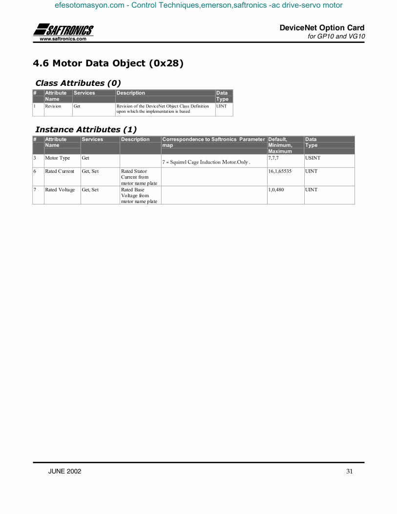
4.6 Motor Data Object (0x28)
Class Attributes (0)# Attribute
NameServices Description Data
Type1 Revis ion Get Revis ion of the DeviceNet Object Class Definition
upon which the implementation is basedUINT
Instance Attributes (1)# Attribute
NameServices Description Correspondence to Saftronics Parameter
mapDefault,Minimum,Maximum
DataType
3 Motor Type Get7 = Squirrel Cage Induction Motor.Only .
7,7,7 USINT
6 Rated Current Get, Set Rated StatorCurrent frommotor name plate
16,1,65535 UINT
7 Rated Voltage Get, Set Rated BaseVoltage frommotor name plate
1,0,480 UINT
efesotomasyon.com - Control Techniques,emerson,saftronics -ac drive-servo motor

DeviceNet Option Cardfor GP10 and VG10
32 JUNE 2002
4.7 Control Supervisor Object (0x29)
Class Attributes (0)AttributeName
Services Description DataType
1 Revis ion Get Revis ion of the DeviceNet Object Class Definitionupon which the implementation is based
UINT
Instance Attributes (1)# Attribute Name Services Correspondence to Saftronics Parameter
mapDataType
3 Run 1 Get, Set Bit 0 = 1 of S06 BOOL
4 Run 2 Get, Set Bit 1 = 1 of S06 BOOL
5 Net Control Get, Set NetCtrl = 1 If NetRef = 1 ThenH30 = 3If Net Ref = 0 ThenH30 = 2
BOOL
NetCtrl =0 If NetRef = 1 ThenH30 = 1If Net Ref = 0 ThenH30 =0
6 State Get 1=Start/up 2=Not_ready 3=Ready4=Enabled 5=Stopping 6= FaultStop7=Faulted
UINT
7 Running 1 Get Bit0=1 of M14 BOOL
8 Running2 Get Bit1=1 of M14 BOOL
9 Ready Get 1=Ready or Enabled or Stopping0=Other State
BOOL
10 Faulted Get Bit11 =1 of M14 BOOL
11 Warning Get BOOL
12 FaultRst Get, Set Bit 15 = 0 to 1 and 1 to 0 of S06 BOOL
15 CtlFromNet Get When H30 = 2 or 3, and bit 12 of M14 ,CtlFromNet=1.Otherwise CtlFromNet=0.
BOOL
16 DNFaultMode Get, Set 0 is equivalent to o27 = 0, 1 is equivalentto o27 = 3, 2 is equivalent to o27 = 2
USINT
efesotomasyon.com - Control Techniques,emerson,saftronics -ac drive-servo motor

DeviceNet Option Cardfor GP10 and VG10
JUNE 2002 33
Run/Stop Event MatrixRunFwd RunRev Trigger
EventRun Type
0 0 Stop N/A
0->1 0 Run RunFwd0 0->1 Run RunRev0->1 0->1 No Action N/A1 1 No Action N/A1->0 1 Run RunRev1 1->0 Run RunFwd
State transition diagram
Non Existent
Startup
Power On
Ready
Power-on AND RDY Power-on AND not RDY
Power Off
Enabled
FWD OR REV Stopping
Fault_Stop
Faulted
Not Ready
Power On
FWD OR REV
ALM=1
ALM=1
FaultRst
ALM=1
DEC=0
DEC=0
DEC=1
ALM=1
efesotomasyon.com - Control Techniques,emerson,saftronics -ac drive-servo motor

DeviceNet Option Cardfor GP10 and VG10
34 JUNE 2002
4.8 AC/DC-Drive Object (0x2A)
Class Attributes (0)# Attribute
NameServices Description Data
Type1 Revis ion Get Revis ion of the DeviceNet Object Class Definition
upon which the implementation is basedUINT
Instance Attributes (1)# Attribute Name Services Correspondence to Saftronics
Parameter mapDataType
3 At Reference Get Frequency arrival BOOL
When H30= 1 or 3,and bit 12 ofM14=1
NetRef=1Get
Otherwise NetRef=0NetRef = 1 If NetCtrl = 1 Then H30 = 3
If NetCtrl = 0 Then H30 = 1
4 NetRef
Set
NetRef = 0 If NetCtrl = 1 Then H30 = 2If NetCtrl = 0 Then H30 = 0
BOOL
6 Drive mode Get 0= Vendorspecific mode; USINT
7 Speed Actual Get M06 Units RPM/2SpeedScale UINT
8 SpeedRef Get, Set S01 Units RPM/2SpeedScale UINT
17 Output Volatage Get M12 Units V/2VoltageScale UINT
18 AccelTime Get, Set S08 Units msec/2TimeScale UINT
19 DecelTime Get, Set S09 Units msec/2TimeScale UINT
20 LowSpdLimit Get, Set F16 Units RPM/2SpeedScale UINT
21 HighSpeedLimit Get, Set Maximum output frequency UnitsRPM/2SpeedScale
UINT
22 Speed Scale (Note2) Get, Set Internal in AnyBus USINT
23 Current Scale (Note2) Get, Set Internal in AnyBus USINT
27 Volatge Scale (Note2) Get, Set Internal in AnyBus USINT
28 Time Scale (Note2) Get, Set Internal in AnyBus USINT
29 RefFromNet Get Reflects NetRef BOOL
Note1: Since the resolution of AcelTime and DecelTime are 1mS and the data type is 16bit unsigned. Please use the Timescale for other resolutions if necessary.Note2: If the devicenetmodule returns a NACK (Invalid parameter) when trying to write to the scaleparameters (Attributes22,23,27 and 28), a powercycle of the module must be done (Turn the power off and on), to be able to store thescaleparametervalues again.
efesotomasyon.com - Control Techniques,emerson,saftronics -ac drive-servo motor

DeviceNet Option Cardfor GP10 and VG10
JUNE 2002 35
4.9 Saftronics VendorSpecific Object (0x64)
Class Attributes (0)# Attribute
NameServices Description Data
Type1 Revis ion Get_Attr ibute_Single Revis ion of the VendorSpecific Object Class
Definition upon which the implementation is basedUINT
Instance Attributes (1)# Services Attribute
NameCorrespondence to SaftronicsParameter map
DataType
0 Get_Attribute_Single
Attribute 1 Revision of the class
First revision is 1.1
Size: 1 word.
USINT,USINT
Attribute 1 Parameter 1 in the Saftronics parameterlist
Size: 1 word
UINT
Attribute 2 Parameter 2 in the VG10/GP10parameter list
Size: 1 word
UINT
Attribute n Parameter n in the VG10/GP10parameter list
Size: 1 word
UINT
1 Get, Set
Attribute255
Parameter 255 in the VG10/GP10parameter list
Size: 1 word
UINT
Note:This table is only providing the method of reading and writing the parameters, the format and meaning is explained in detail inthe next section.
efesotomasyon.com - Control Techniques,emerson,saftronics -ac drive-servo motor
DeviceNet Option Cardfor GP10 and VG10
36 JUNE 2002
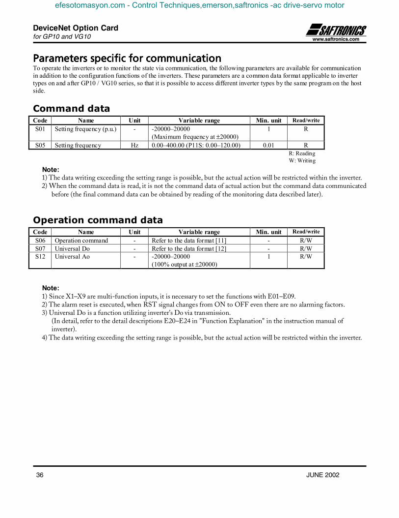
Parameters specific for communicationParameters specific for communicationParameters specific for communicationParameters specific for communicationTo operate the inverters or to monitor the state via communication, the following parameters are available for communicationin addition to the configuration functions of the inverters. These parameters are a common data format applicable to invertertypes on and after GP10 / VG10 series, so that it is possible to access different inverter types by the same program on the hostside.
Command dataCode Name Unit Variable range Min. unit Read/writeS01 Setting frequency (p.u.) - -20000–20000
(Maximum frequency at ±20000)1 R
S05 Setting frequency Hz 0.00–400.00 (P11S: 0.00–120.00) 0.01 R
Note:1) The data writing exceeding the setting range is possible, but the actual action will be restricted within the inverter.2) When the command data is read, it is not the command data of actual action but the command data communicated
before (the final command data can be obtained by reading of the monitoring data described later).
Operation command dataCode Name Unit Variable range Min. unit Read/writeS06 Operation command - Refer to the data format [11] - R/WS07 Universal Do - Refer to the data format [12] - R/WS12 Universal Ao - -20000–20000
(100% output at ±20000)1 R/W
Note:1) Since X1–X9 are multi-function inputs, it is necessary to set the functions with E01–E09.2) The alarm reset is executed, when RST signal changes from ON to OFF even there are no alarming factors.3) Universal Do is a function utilizing inverter’s Do via transmission.
(In detail, refer to the detail descriptions E20–E24 in "Function Explanation" in the instruction manual ofinverter).
4) The data writing exceeding the setting range is possible, but the actual action will be restricted within the inverter.
R: ReadingW: Writing
efesotomasyon.com - Control Techniques,emerson,saftronics -ac drive-servo motor
DeviceNet Option Cardfor GP10 and VG10
JUNE 2002 37
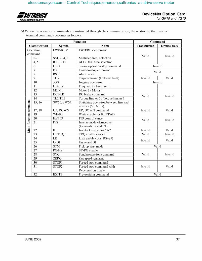
5) When the operation commands are instructed through the communication, the relation to the inverterterminal commands becomes as follows.
Function CommandClassification Symbol Name Transmission Terminal block
Operationcommand
FWD/REV FWD/REV command
0–3 SS1, 2, 4, 8 Multistep freq. selection4, 5 RT1, RT2 ACC/DEC time selection
Valid Invalid
6 HLD 3-wire operation stop command Invalid7 BX Coast-to-stop command8 RST Alarm reset Valid
9 THR Trip command (External fault) Invalid Valid10 JOG Jogging operation Invalid11 Hz2/Hz1 Freq. set. 2 / Freq. set. 112 M2/M1 Motor 2 / Motor 113 DCBRK DC brake command14 TL2/TL1 Torque limiter 2 / Torque limiter 115, 16 SW50, SW60 Switching operation between line and
inverter (50, 60Hz)
Valid Invalid
17, 18 UP, DOWN UP, DOWN command Invalid Valid19 WE-KP Write enable for KEYPAD20 Hz/PID PID control cancel21 IVS Inverse mode changeover
(terminals 12 and C1)
Valid Invalid
22 IL Interlock signal for 52-2 Invalid Valid23 Hz/TRQ TRQ control cancel Valid Invalid24 LE Link enable (Bus, RS485)25 U-DI Universal DI Invalid Valid
26 STM Pick up start mode Valid27 PG/Hz SY-PG enable28 SYC Synchronization command29 ZERO Zero speed command
Valid Invalid
30 STOP1 Forced stop command31 STOP2 Forced stop command with
Deceleration time 4Invalid Valid
Mul
ti-fu
nctio
n co
mm
and
32 EXITE Pre-exciting command Valid
efesotomasyon.com - Control Techniques,emerson,saftronics -ac drive-servo motor
DeviceNet Option Cardfor GP10 and VG10
38 JUNE 2002
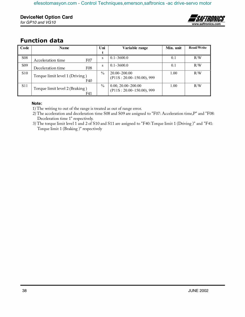
Function dataCode Name Uni
tVariable range Min. unit Read/Write
S08 Acceleration time F07 s 0.1–3600.0 0.1 R/W
S09Deceleration time F08
s 0.1–3600.0 0.1 R/W
S10Torque limit level 1 (Driving )
F40
% 20.00–200.00(P11S : 20.00–150.00), 999
1.00 R/W
S11Torque limit level 2 (Braking )
F41
% 0.00, 20.00–200.00(P11S : 20.00–150.00), 999
1.00 R/W
Note:1) The writing to out of the range is treated as out of range error.2) The acceleration and deceleration time S08 and S09 are assigned to "F07: Acceleration time‚P" and "F08:
Deceleration time 1" respectively.3) The torque limit level 1 and 2 of S10 and S11 are assigned to "F40: Torque limit 1 (Driving )" and "F41:
Torque limit 1 (Braking )" respectively
efesotomasyon.com - Control Techniques,emerson,saftronics -ac drive-servo motor

DeviceNet Option Cardfor GP10 and VG10
JUNE 2002 39
Monitoring dataCode Description Unit Range Min. unit Read/Write
M01 Setting frequency(Final data)
- -20000–20000(Maximum frequency at ±20000)
1 R
M05 Setting frequency(Final data)
Hz 0–400.00 (P11S: 0.00–120.00) 0.01 R
M06 Output frequency 1 - -20000–20000(Maximum frequency at ±20000)
1 R
M07 Torque calculation value % -200.00–200.00 0.01 R
M08 Torque current % -200.00–200.00 0.01 R
M09 Output frequency 1 Hz 0.00–400.00 (P11S0.00–120.00 ) 0.01 R
M10 Input power % 0.00–200.00 0.01 R
M11 Output current % 0.00–200.00 (Inverter rating at 100.00) 0.01 R
M12 Output voltage V 0.0–600.0 1.0 R
M13 Operation command(Final data)
- Refer to the data format [11] - R
M14 Operating state - Refer to the data format [13] - R
M15 Y1-Y5 output terminal data - Refer to the data format [12] - R
M16 Fault memory 0 -
M17 Fault memory (1st prior) -
M18 Fault memory (2nd prior) -
M19 Fault memory (3rd prior) -
Refer to the Alarm code table below - R
M20 Operating time h 0–65535 1 R
M21 DC link circuit voltage V 0–1000 1 R
M23 Type code - Refer to the data format [14] - R
M24 Capacity code - Refer to the data format [9] - R
M25 ROM version - 0–64999 1 R
M26 Transmission error code (RS 485) - Refer to the Alarm code table below - R
M27 Setting frequency at alarming(Final data)
- -20000–20000(Maximum frequency at 20000)
1 R
M31 Setting Frequency at alarming(Final data)
Hz 0–400.00 (P11S: 0.00–120.00) 0.01 R
M32 Output frequency at alarming - -20000–20000(Maximum frequency at ±20000)
1 R
M33 Torque calculation value at alarming % -200.00–200.00 0.01 R
M34 Torque current at alarming % -200.00–200.00 0.01 R
M35 Output frequency 1 at alarming Hz -400.00–400.00(P11S: -120.00–120.00)
0.01 R
M36 Input power at alarming % 0.00–200.00 0.01 R
M37 Output current at alarming % 0.00–200.00 (Inverter rating at 100.00) 0.01 R
efesotomasyon.com - Control Techniques,emerson,saftronics -ac drive-servo motor

DeviceNet Option Cardfor GP10 and VG10
40 JUNE 2002
M38 Output voltage at alarming V 0.0–600.0 1.0 R
M39 Operation command at alarming - Refer to the data format [11] - R
M40 Operating state at alarming - Refer to the data format [13] - R
M41 Y1-Y5 output terminal data at alarming - Refer to the data format [12] - R
M42 Operation time at alarming H 0–65535 1 R
M43 DC link circuit voltage at alarming V 0–1000 1 R
M44 Inverter internal air temp. at alarming °C 0–120 1 R
M45 Cooling fin temp. at alarming °C 0–120 1 R
M46 Life of main circuit capacitor % 0.0–100.0 0.1 R
M47 Life of printed circuit board capacitor H 0–65535 1 R
M48 Life of cooling fan H 0–65535 1 R
Note :1) The output frequency 1 is before slip compensation.2) The output frequency 1 with speed regulator (using option OPC-G11S-PG) is treated as the synchronous frequency.3) Alarm code
Code Description Code Description
0 No alarm --- 28 PG error Pg
1 Overcurrent (During acceleration) OC1 31 Memory error Er1
2 Overcurrent (During deceleration) OC2 32 KEYPAD panel communication error Er2
3 Overcurrent (While running a t constant speed) OC3 33 CPU error Er3
5 Ground fault EF 34 Option communication error Er4
6 Overvoltage (During acceleration) OU1 35 Option error Er5
7 Overvoltage (During deceleration) OU2 36 Operating proc. error Er6
8 Overvoltage (While running a t constant speed) OU3 37 Output phase loss error Er7
10 Undervoltage LU 38 RS485 communication error Er8
11 Input phase lose Lin 71 Check sum error
14 Fuse blown FUS 72 Parity error
16 Output wiring error Er7 73 Other errors
17 Overheat of heat sink in inverter OH1 74 Format error
18 External alarm input OH2 75 Command error
19 Overheat of unit internal temp. OH3 76 Priority of link
22 Overheat of DB resistance dbH 77 No writing right for error
23 Electronic thermal overload relay (Motor 1) OL1 78 Function code error
24 Electronic thermal overload relay (Motor 2) OL2 79 Forbidden writing error
25 Electronic thermal overload relay (Inverter) OLU 80 Data error
27 Overspeed OS 81 Error during writing
efesotomasyon.com - Control Techniques,emerson,saftronics -ac drive-servo motor

DeviceNet Option Cardfor GP10 and VG10
JUNE 2002 41
Parameter data formatThe data formats for various parameter data of the inverters are defined here. The data shall be prepared according to thefollowing data format specifications. The instruction manual of inverter shall be referred to for the range and unit of data. Thecommunication number is used to access inverter parameters through the fieldbus option and to configure process dataexchange.
List of parameter data formatCode Commu-
nicationNo.decimal(Hex.)
Name DataFormat
Code Commu-nicationNo. decimal(Hex.)
Name DataFormat
- 0 - - M31 45(2D) Setting frequency at alarming [5]
S01 1(1) Setting frequency (p.u.) [2] (Final data)
- 2(2) - - M32 46(2E) Output frequency at alarming [2]
- 3(3) - - M33 47(2F) Torque calculation value at alarming [6]
- 4(4) - - M34 48(30) Torque current at alarming [6]
S05 5(5) Setting frequency [5] M35 49(31) Output frequency 1 at alarming [5]
S06 6(6) Operation command [11] M36 50(32) Input power at alarming [5]
S07 7(7) Universal Do [12] M37 51(33) Output current at alarming [5]
S08 8(8) Acceleration time [3] M38 52(34) Output voltage at alarming [3]
S09 9(9) Deceleration time [3] M39 53(35) Operation command at alarming [11]
S10 10(A) Torque limit level 1 [5] *1 M40 54(36) Operating state at alarming [13]
S11 11(B) Torque limit level 1 [5] *1 M41 55(37) Y1-Y5 output terminal data at [12]
S12 12(C) Universal Ao [2] alarming
- 13(D) - - M42 56(38) Operating time at alarming [1]
- 14(E) - - M43 57(39) DC link circuit voltage at alarming [1]
M01 15(F) Setting frequency (Final data) [2] M44 58(3A) Inverter internal air temp. at [1]
- 16(10) - - alarming
- 17(11) - - M45 59(3B) Cooling fin temp. at alarming [1]
- 18(12) - - M46 60(3C) Life of main circuit capacitor [3]
M05 19(13) Setting frequency (Final data) [5] M47 61(3D) Life of printed circuit board capacitor [1]
M06 20(14) Output frequency 1 [2] M48 62(3E) Life of cooling fan [1]
M07 21(15) Torque calculation value [6] - 63(3F) - -
M08 22(16) Torque current [6] - 64(40) - -
M09 23(17) Output frequency 1 [5] - 65(41) - -
M10 24(18) Input power [5] - 66(42) - -
M11 25(19) Output current [5] - 67(43) - -
M12 26(1A) Output voltage [3] - 68(44) - -
efesotomasyon.com - Control Techniques,emerson,saftronics -ac drive-servo motor

DeviceNet Option Cardfor GP10 and VG10
42 JUNE 2002
M13 27(1B) Operation command (Final data) [11] - 69(45) - -
M14 28(1C) Operating state [13] F00 70(46) Data protection [1]
M15 29(1D) Y1-Y5 output terminal data [12] F01 71(47) Frequency command 1 [1]
M16 30(1E) Fault memory 0 [1] F02 72(48) Operation method [1]
M17 31(1F) Fault memory (1st prior) [1] F03 73(49) Maximum output frequency 1 [1]
M18 32(20) Fault memory (2nd prior) [1] F04 74(4A) Base frequency 1 [1]
M19 33(21) Fault memory (3rd prior) [1] F05 75(4B) Rated voltage 1 [1]
M20 34(22) Operating time [1] F06 76(4C) Maximum output voltage 1 [1]
M21 35(23) DC link circuit voltage [1] F07 77(4D) Acceleration time 1 [10]
- 36(24) - - F08 78(4E) Deceleration time 1 [10]
M23 37(25) Type code [14] F09 79(4F) Torque boost 1 [3]
M24 38(26) Capacity code [9] F10 80(50) Electronics thermal overload relay 1 [1]
M25 39(27) ROM version [1] (Selection)
M26 40(28) Transmission error processing [1] F11 81(51) Electronics thermal overload relay 1 [10]
Code (Level)
M27 41(29) Setting frequency at alarming [2] F12 82(52) Electronics thermal overload relay 1 [3]
(Final data) F13 83(53) Electronics thermal overload relay [1]
- 42(2A) - - (Braking resistor)
- 43(2B) - - F14 84(54) Restart after momentary power failure [1]
- 44(2C) - - (Selection)
*1) 999 is treated as 7FFFH.
efesotomasyon.com - Control Techniques,emerson,saftronics -ac drive-servo motor

DeviceNet Option Cardfor GP10 and VG10
JUNE 2002 43
Code Commu-nicationNo.decimal(Hex.)
Name DataFormat
Code Commu-nicationNo.decimal(Hex.)
Name DataFormat
F15 85(55) Frequency limiter (High) [1] E37 135(87) Overload early warning 2 (level) [10]
F16 86(56) Frequency limiter (Low) [1] E40 136(88) Display coefficient A [10]
F17 87(57) Gain (for frequency setting signal) [3] E41 137(89) Display coefficient B [10]
F18 88(58) Bias frequency [4] E43 138(8A) LED monitor (Display selection) [1]
F20 89(59) DC brake (Starting frequency) [3] E44 139(8B) LED monitor (Display at STP mode) [1]
F21 90(5A) DC brake (Braking level) [1] E45 140(8C) LCD monitor (Display selection) [1]
F22 91(5B) DC brake (Braking time) [3] C01 141(8D) Jump frequency 1 [1]
F23 92(5C) Starting frequency [3] C02 142(8E) Jump frequency 2 [1]
F24 93(5D) Starting frequency (Holding time) [3] C03 143(8F) Jump frequency 3 [1]
F25 94(5E) Stop frequency [3] C04 144(90) Jump frequency (Width) [1]
F26 95(5F) Motor sound (Carrier frequency) [1] *1 C05 145(91) Multi-step frequency 1 [5]
F27 96(60) Motor sound (Sound tone) [1] C06 146(92) Multi-step frequency 2 [5]
F30 97(61) FMA terminal (Voltage adjust) [1] C07 147(93) Multi-step frequency 3 [5]
F31 98(62) FMA terminal (Function selection) [1] C08 148(94) Multi-step frequency 4 [5]
F33 99(63) FMP terminal (Pulse rate multiplier) [1] C09 149(95) Multi-step frequency 5 [5]
F34 100(64) FMP terminal (Voltage adjust) [1] C10 150(96) Multi-step frequency 6 [5]
F35 101(65) FMP terminal (Function selection) [1] C11 151(97) Multi-step frequency 7 [5]
F36 102(66) 30Ry operation mode [1] C20 152(98) Jogging frequency [5]
C30 153(99) Frequency setting 2 [1]
F40 103(67) Torque limit 1 (Driving) [1] C31 154(9A) Analog input offset (terminal 12) / [4]
F41 104(68) Torque limit 1 (Braking) [1] Analog input bias (terminal 12)
F42 105(69) Torque vector control 1 [1] C32 155(9B) Analog input offset (terminal C1) / [4]
E01 106(6A) X1 terminal function [1] Analog input gain (terminal 12)
E02 107(6B) X2 terminal function [1] C33 156(9C) Analog filter [5]
E03 108(6C) X3 terminal function [1] P01 157(9D) Motor 1 (Number of poles) [1]
E04 109(6D) X4 terminal function [1] P02 158(9E) Motor 1 (Capacity) [5]
E05 110(6E) X5 terminal function [1] P03 159(9F) Motor 1 (Rated current) [10]
E06 111(6F) X6 terminal function [1]
E07 112(70) X7 terminal function [1] P05 161(A1) Motor 1 (On-line tuning) [1]
E08 113(71) X8 terminal function [1] P06 162(A2) Motor 1 (No-load current) [10]
E09 114(72) X9 terminal function [1] P07 163(A3) Motor 1 (%R1) [5]
E10 115(73) Acceleration time 2 [10] P08 164(A4) Motor 1 (%X) [5]
E11 116(74) Deceleration time 2 [10] P09 165(A5) Motor 1 (Slip compensation control ) [5]
efesotomasyon.com - Control Techniques,emerson,saftronics -ac drive-servo motor
DeviceNet Option Cardfor GP10 and VG10
44 JUNE 2002
E12 117(75) Acceleration time 3 [10] H03 166(A6) Data initializing [1] *2
E13 118(76) Deceleration time 3 [10] H04 167(A7) Auto-reset (Times) [1]
E14 119(77) Acceleration time 4 [10] H05 168(A8) Auto-reset(Reset interval) [1]
E15 120(78) Deceleration time 4 [10] H06 169(A9) Fan stop operation [1]
E16 121(79) Torque limiter 1 (Driving) [1] H07 170(AA) ACC/DCC pattern (Mode selection) [1]
E17 122(7A) Torque limiter 1 (Braking) [1] H08 171(AB) Reverse phase sequence lock [1]
E20 123(7B) Y1 terminal function [1] H09 172(AC) Start mode (Pick-up mode) [1]
E21 124(7C) Y2 terminal function [1] H10 173(AD) Energy-saving operation [1]
E22 125(7D) Y3 terminal function [1] H11 174(AE) Deceleration mode [1]
E23 126(7E) Y4 terminal function [1] H12 175(AF) Instantaneous overcurrent limiting [1]
E24 127(7F) Y5A, Y5C terminal functions [1] H13 176(B0) Auto-restart (Restart time) [3]
H14 177(B1) Auto-restart (Frequency fall rate) [5]
E30 128(80) Frequency arrival (FAR) [3] H15 178(B2) Auto-restart (Holding DC voltage) [1]
(Detecting width) H16 179(B3) Auto-restart [3] *3
E31 129(81) Frequency detection 1 (FDT) [1] (OPR command selfhold time)
(level) H18 180(B4) Torque control (Mode selection) [1]
E32 130(82) Frequency detection (FDT) [3] H19 181(B5) Active drive [1]
(Hysteresis width) H20 182(B6) PID control (Mode selection) [1]
E33 131(83) Overload early warning [1] H21 183(B7) PID control (Feed back signal) [1]
(Mode selection) H22 184(B8) PID control (P-Gain) [5]
E34 132(84) Overload early warning 1 (level) [10] H23 185(B9) PID control (I-time) [3]
E35 133(85) Overload early warning (Timer time) [3] H24 186(BA) PID control (D-time) [5]
E36 134(86) Frequency detection 2 (FDT) (level) [1] H25 187(BB) PID control (Feedback filter) [3]
*1) 0.75 kHz is treated as 0000H*2) The communication might not be able to be continued by writing (data 1).*3) 999 is treated as 03E7H (99.9).
efesotomasyon.com - Control Techniques,emerson,saftronics -ac drive-servo motor

DeviceNet Option Cardfor GP10 and VG10
JUNE 2002 45
Code Commu-nicationNo.decimal(Hex.)
Name DataFormat
Code Commu-nicationNo.decimal(Hex.)
Name DataFormat
H26 188(BC) PTC thermistor (Mode selection) [1] o36 235(EB) Bus Configuration Parameter 07 [1]
H27 189(BD) PTC thermistor (Level) [5] o37 236(EC) Bus Configuration Parameter 08 [1]
H28 190(BE) Droop operation [4] o38 237(ED) Bus Configuration Parameter 09 [1]
H30 191(BF) Serial link (Function selection) [1] o39 238(EE) Bus Configuration Parameter 10 [1]
H31 192(C0) RS485 (Address) [1] *1 o40 239(EF) Bus Configuration Parameter 11 [1]
H32 193(C1) RS485 (Mode selection on error) [1] *1 o41/ 240(F0) Bus Configuration Parameter 12/ [1] /
H33 194(C2) RS485 (Timer time) [3] *1 (o09) Base side number of encoder pulses [1]
H34 195(C3) RS485 (Baud rate) [1] *1 o42/ 241(F1) Bus Configuration Parameter 13/ [1] /
H35 196(C4) RS485 (Data length) [1] *1 (o10) Time constant of pulse train inputfilter
[7]
H36 197(C5) RS485 (Parity check) [1] *1 o43/ 242(F2) Bus Configuration Parameter 14/ [1] /
H37 198(C6) RS485 (Stop bits) [1] *1 (o11) Command pulse compensationcoefficient 1
[1]
H38 199(C7) RS485 (No response detection time) [1] *1 o44/ 243(F3) Bus Configuration Parameter 15/ [1] /
H39 200(C8) RS485 (Response interval) [5] *1 (o12) Command pulse compensationcoefficient 2
[1]
A01 201(C9) Maximum frequency 2 [1] o45/ 244(F4) Bus Configuration Parameter 16/ [1] /
A02 202(CA) Base frequency 2 [1] (o13) Main speed regulator gain [3]
A03 203(CB) Rated voltage 2 (at base speed) [1] o46/ 245(F5) Bus Configuration Parameter 17/ [1] /
A04 204(CC) Maximum output voltage 2 [1] (o14) APR P gain [5]
A05 205(CD) Torque boost 2 [3] o47/ 246(F6) Bus Configuration Parameter 18/ [1] /
A06 206(CE) Electronics thermal 2 (Selection) [1] (o15) Z phase matching gain [3]
A07 207(CF) Electronics thermal 2 (Level) [10] o48/ 247(F7) Bus Configuration Parameter 19/ [1] /
A08 208(D0) Electronics thermal 2 [3] (o16) Offset angle [1]
(Thermal time constant) o49/ 248(F8) Bus Configuration Parameter 20/ [1] /
A09 209(D1) Torque vector control 2 [1] (o17) Detecting angle width for completion [1]
A10 210(D2) Motor 2 (Number of motor-2 poles) [1] of synchronizing
A11 211(D3) Motor 2 (Capacity) [5] o50/ 249(F9) Bus Configuration Parameter 21/ [1] /
A12 212(D4) Motor 2 (Rated current) [10] (o18) Too mach deviation [1]
A14 214(D6) Motor 2 (On-line tuning) [1]
A15 215(D7) Motor 2 (No load current [10]
A16 216(D8) Motor 2 (%R1 setting) [5]
A17 217(D9) Motor 2 (%X setting) [5]
A18 218(DA) Motor 2 (Slip compensation control 2) [5]
o01 219(DB) Speed command system / [15]
efesotomasyon.com - Control Techniques,emerson,saftronics -ac drive-servo motor

DeviceNet Option Cardfor GP10 and VG10
46 JUNE 2002
automatic speed control system
o02 220(DC) Time constant of PG vector and [7]
speed command filter
o03 221(DD) Number of feedback PG pulses [1]
o04 222(DE) Constant P of feedback speed [5]
Controller
o05 223(DF) Constant I of feedback speed [7]
Controller
o06 224(E0) Time constant of feedback [7]
speed detection filter
o07 225(E1) Feedback pulse correction [1]
coefficient 1
o08 226(E2) Feedback pulse correction [1]
coefficient 2
o27 227(E3) Mode selection on error [1]
o28 228(E4) Timer time setting [3]
o30 229(E5) Bus Configuration Parameter 01 [1]
o31 230(E6) Bus Configuration Parameter 02 [1]
o32 231(E7) Bus Configuration Parameter 03 [1]
o33 232(E8) Bus Configuration Parameter 04 [1]
o34 233(E9) Bus Configuration Parameter 05 [1]
o35 234(EA) Bus Configuration Parameter 06 [1]
*1) Read-only from communication.
efesotomasyon.com - Control Techniques,emerson,saftronics -ac drive-servo motor
DeviceNet Option Cardfor GP10 and VG10
JUNE 2002 47
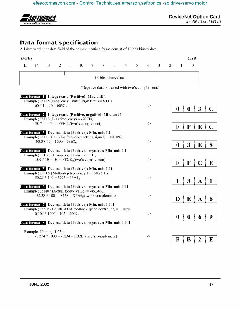
Data format specificationAll data within the data field of the communication frame consist of 16 bits binary data.
(MSB) (LSB)
15 14 13 12 11 10 9 8 7 6 5 4 3 2 1 0
16-bits binary data
(Negative data is treated with two’s complement.)
Data format [1] Integer data (Positive): Min. unit 1Example) If F15 (Frequency limiter, high limit) = 60 Hz,
60 * 1 = 60 = 003CH ->
Data format [2] Integer data (Positive, negative): Min. unit 1Example) If F18 (Bias frequency) = -20 Hz,
-20 * 1 = -20 = FFECH(two’s complement) ->
Data format [3] Decimal data (Positive): Min. unit 0.1Example) If F17 Gain (for frequency setting signal) = 100.0%,
100.0 * 10 = 1000 = 03E8H ->
Data format [4] Decimal data (Positive, negative): Min. unit 0.1Example) If H28 (Droop operation) = -5.0Hz,
-5.0 * 10 = -50 = FFCEH(two’s complement) ->
Data format [5] Decimal data (Positive): Min. unit 0.01Example) If C05 (Multi-step frequency 1) = 50.25 Hz,
50.25 * 100 = 5025 = 13A1H ->
Data format [6] Decimal data (Positive, negative): Min. unit 0.01Example) If M07 (Actual torque value) = -85.38%,
-85.38 * 100 = -8538 = DEA6H(two’s complement) ->
Data format [7] Decimal data (Positive): Min. unit 0.001Example) If o05 (Constant I of feedback speed controller) = 0.105s,
0.105 * 1000 = 105 = 0069H ->
Data format [8] Decimal data (Positive, negative): Min. unit 0.001
Example) If being -1.234, -1.234 * 1000 = -1234 = FB2EH(two’s complement) ->
0 0 3 C
F F E C
0 3 E 8
F F C E
1 3 A 1
D E A 6
0 0 6 9
F B 2 E
efesotomasyon.com - Control Techniques,emerson,saftronics -ac drive-servo motor

DeviceNet Option Cardfor GP10 and VG10
48 JUNE 2002
Data format [9] Capacity code
Code Capacity (kW) Code Capacity (kW) Code Capacity (kW)
5 0.05 1100 11 11000 110
10 0.1 1500 15 13200 132
20 0.2 1850 18.5 16000 160
40 0.4 2200 22 20000 200
75 0.75 3000 30 22000 220
150 1.5 3700 37 25000 250
220 2.2 4500 45 28000 280
370 3.7 5500 55 31500 315
550 5.5 7500 75 35500 355
750 7.5 9000 90 40000 400
Example) If 30kWSince 30 * 100 = 3000 = 0BB8H ->
Data format [10] Exponential data (ACC/DEC time, current value, display coefficient)
(MSB) (LSB)
15 14 13 12 11 10 9 8 7 6 5 4 3 2 1 0
Polarity 0 0 0 Indexpotion
Data portion
0: 0.01 * 001–999 (0.00 – 9.99) 1: 0.1 * 100–999 (10.0 – 99.9) 2: 1 * 100–999 (100 – 999) 3: 10 * 100–999 (1000 – 3600)
0: Positive (+), 1:Negative (-)
Example) F07 (Acceleration time 1) = 20.0 s,20.0 = 0.1 * 200 ->
0 B B 8
0 4 C 8
Not used
efesotomasyon.com - Control Techniques,emerson,saftronics -ac drive-servo motor

DeviceNet Option Cardfor GP10 and VG10
JUNE 2002 49
Data format [11] Operation command
15 14 13 12 11 10 9 8 7 6 5 4 3 2 1 0(R
ST)
0 0 0 0 X9 X8 X7 X6 X5 X4 X3 X2 X1
REV
FWD
Alarm reset Not used Multi-function command FWD: Forward rotation command command
REV: Reverse rotation command
(All bits are ON by 1)Example) If M13 (Operation command, Final command) = FWD, X1, X5 = ON,
0000 0000 0100 0101b = 0045H ->
Data format [12] Universal output terminal
15 14 13 12 11 10 9 8 7 6 5 4 3 2 1 0
0 0 0 0 0 0 0 0 0 0 0 Y5 Y4 Y3 Y2 Y1
Not used Universal command
(All bits are ON by 1)
Example) If M15 (Universal output terminal) = Y1, Y5 = ON,0000 0000 0001 0001b.= 0011H ->
0 0 4 5
0 0 1 1
efesotomasyon.com - Control Techniques,emerson,saftronics -ac drive-servo motor

DeviceNet Option Cardfor GP10 and VG10
50 JUNE 2002
Data format [13] Operating status
15 14 13 12 11 10 9 8 7 6 5 4 3 2 1 0
- WR RL ALM DEC ACC IL VL TL NUV BRK INT EXT REV FWD
(All bit are ON or active by 1)
FWD: In forward operation IL: In current limitingREV: In reverse operation ACC: In accelerationEXT: In DC braking (or in pre-excitation) DEC: In deceleration
ALM: AlarmINT: Inverter Base Of RL: Transmission validBRK: In braking WR: Function writing rightNUV: DC link voltage is establishment
(Undervoltage condition at 0) 0: Keypad panel
1: RS485TL: In torque limiting 2: Link (option)VL: In voltage limiting
Example) Omitted (Monitoring method is similar as in the formats [11] and [12].)
Data format [14] Type code
15 14 13 12 11 10 9 8 7 6 5 4 3 2 1 0
Unit type Generation Series Voltage series
Code Type Generation Series Voltage series
1 VG 11th series For Japan 100V single phase
2 G - For Asia 200V single phase
3 P - For China 200V three phase
4 E - For Europe 400V three phase
5 C - For USA 575V three phase
6 S - - -
efesotomasyon.com - Control Techniques,emerson,saftronics -ac drive-servo motor

DeviceNet Option Cardfor GP10 and VG10
JUNE 2002 51
Data format [15] Code setting (1 – 4 figures)
15 14 13 12 11 10 9 8 7 6 5 4 3 2 1 0
Data 4 Data 3 Data 2 Data 1
Example) If "o22:Ai function selection" = 123,Since 123 = 0123H ⇒
Action at communication errorIn case of occurring transmission errors (communication cutoff with the master), the following actions can be selected.
1) Select action when error is detected. (o27)o27 Action at error detection Remarks
0 Immediate forced stop Er5
1 Continue operation within o28 time and stop Er5
2 Continue operation according to the last commandreceived until restoration of the communication. Ifthe communication is not restored before the o28time expires, then immediate forced stop
Er5
Continue operation using thecommand just before the errorwithin o28 time, but whenrestoring, operate following tothe designation ofcommunication.
3 Continue operation till restoration of thecommunication, and after the restoration, followto designation of communication.
Automatic restorationafter restoringcommunication
0 1 2 3
efesotomasyon.com - Control Techniques,emerson,saftronics -ac drive-servo motor

DeviceNet Option Cardfor GP10 and VG10
52 JUNE 2002
2) Setting time of timer at error (o28)0.0 – 60.0s
In a case of o27=0 (Mode of immediate forced stop at communication error detection)
Communication state
Display
Internal operation of inverter
Command from Master
Operation command
FWD
Output frequency
Setting frequency
Setting frequency
Normal Error
Normal
Normal Er 5
Alarm reset
Coast-to-stop
Stop Operation
ON
Operation
ON
Communication failure
efesotomasyon.com - Control Techniques,emerson,saftronics -ac drive-servo motor

DeviceNet Option Cardfor GP10 and VG10
JUNE 2002 53
In a case of o27=1, o28=5.0 s (Mode of immediate forced stop after 5 s at occurring communication error)
Normal
Error
Normal
Normal Er 5
Alarm reset
In acceleration, even if occurring transmission error,accelerated to the setting frequency.
Coast-to-stop
Stop Operation
ON
Operation
ON
5.0s *1
OFF Command from Master
Internal operation of inverter
Communication state
Display
Operation command
FWD
Output frequency
Setting frequency
Setting frequency
*1) In a period until restoring the communication, the last commands (command data and operation data) received before theerror are kept.
efesotomasyon.com - Control Techniques,emerson,saftronics -ac drive-servo motor

DeviceNet Option Cardfor GP10 and VG10
54 JUNE 2002
In a case of o27=2, o28=5.0 s (The communication is not restored for 5.0 sec after error detection, and inverter trips Er5.)
Normal
Error
Normal
Normal Er 5
Alarm reset
Coast-to-stop
Stop Operation
ON
Operation
*1 5.0s
ON
Internal operation of inverter
Command from Master
Communication state
Display
Operation command
FWD
Output frequency
Setting frequency
Setting frequency
In acceleration, even if occurring transmission error, accelerated to the setting frequency.
efesotomasyon.com - Control Techniques,emerson,saftronics -ac drive-servo motor

DeviceNet Option Cardfor GP10 and VG10
JUNE 2002 55
In a case of o27=2, o28=5.0 s (A communication error occurs, but restored within 5 s.)
Normal
Error
Normal
Normal
Stop Operation
ON
*1 5.0s
OFF
Internal operation of inverter
Command from Master
Communication state
Display
Operation command
FWD
Output frequency
Setting frequency
Setting frequency
In acceleration, even if occurring transmission error, accelerated to the setting frequency.
*1) In a period until restoring the communication, the commands (command data and operation data) just before the error arekept.
efesotomasyon.com - Control Techniques,emerson,saftronics -ac drive-servo motor
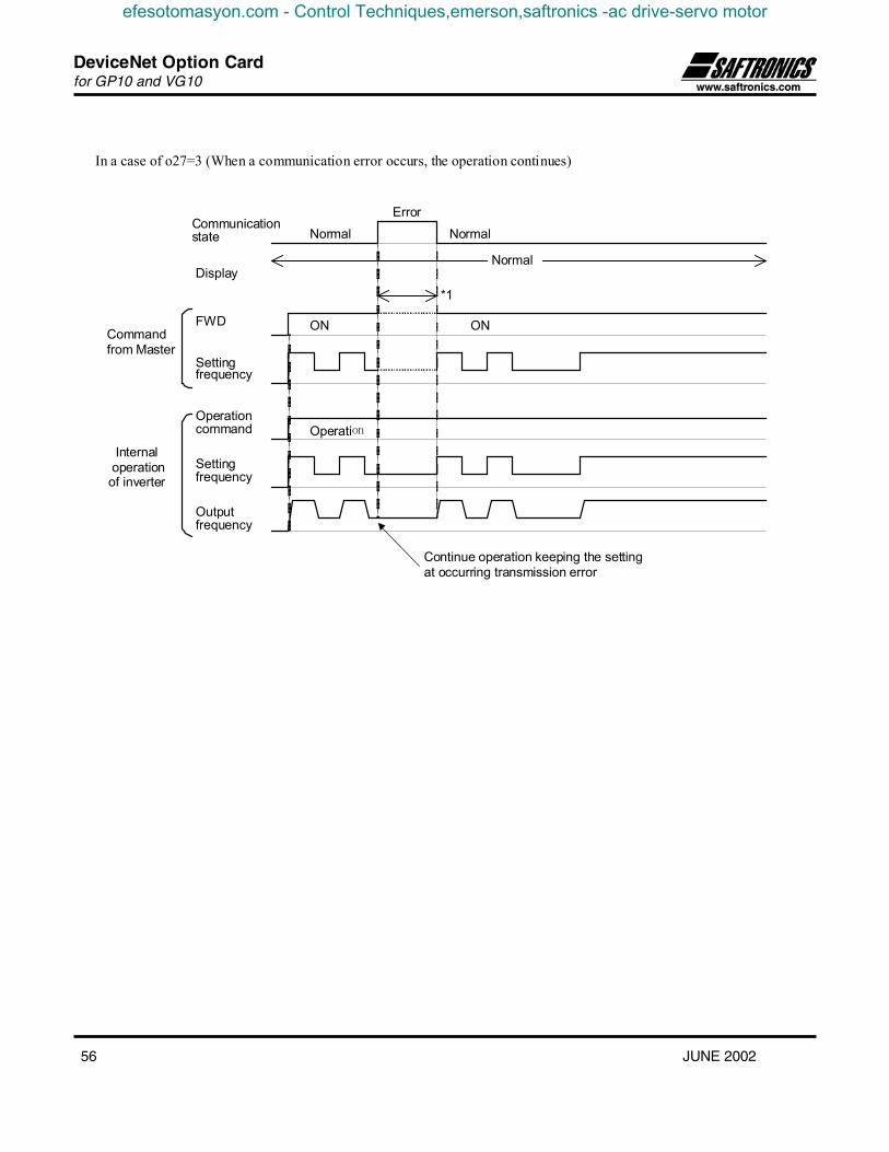
DeviceNet Option Cardfor GP10 and VG10
56 JUNE 2002
In a case of o27=3 (When a communication error occurs, the operation continues)
Normal
Error
Normal
Normal
Operation
ON
*1
ON
Internal operation of inverter
Command from Master
Communication state
Display
Operation command
FWD
Output frequency
Setting frequency
Setting frequency
Continue operation keeping the setting at occurring transmission error
efesotomasyon.com - Control Techniques,emerson,saftronics -ac drive-servo motor

![Analytická geometriestudent21.gjwprostejov.cz/uploads/VG10 Analyticka...počátek kartézské soustavy souřadnic, přímky x, y se nazývají souřadnicové osy. [ ] dvojice je uspořádaná](https://img.dokumen.tips/doc/110x75/5e395fdc603ee72cef702454/analytick-analyticka-potek-kartzsk-soustavy-souadnic-pmky-x.jpg)