Embed Size (px)
Citation preview

DeviceNet™
Fieldbus Interface for S300 / S600 / S700
Edition 07/2014
Translation of the original manual
Keep the manual as a product component
during the life span of the product.
Pass the manual to future users / owners
of the product.
Datei srdnet_e.***

Previous edit ions
Edition Comments
12 / 2002 First edition
07 / 2003New Layout, Object description altered, minor corrections, valid from firmware version S600 5.55,
Declaration of Conformity with DeviceNet™ Specification
03 / 2004 several corrections, valid also for S300 from firmware version 1.0
01 / 2006 chapter 1 restructured, several changes, wording updated
09 / 2006 new design
08 / 2007 Branding, S700 new, standards
12 / 2009 Branding, minor corrections, symbold acc. to ANSI Z535
12 / 2010 Company name
07 / 2014 Design cover page, warning notes updated
SERVOSTAR is a registered trademark of Kollmorgen Corporation
Technical changes to improve the performance of the equipment may be made without prior notice !
Printed in the Federal Republic of Germany
All rights reserved. No part of this work may be reproduced in any form (by photocopying microfilm or any other method)
or processed, copied or distributed by electronic means, without the written permission of Kollmorgen Europe GmbH.

1 General1.1 About this manual . . . . . . . . . . . . . . . . . . . . . . . . . . . . . . . . . . . . . . . . . . . . . . . . . . . . . . . . . . . . . . . . . . . . . . . 7
1.2 Target group . . . . . . . . . . . . . . . . . . . . . . . . . . . . . . . . . . . . . . . . . . . . . . . . . . . . . . . . . . . . . . . . . . . . . . . . . . . 7
1.3 Hints for the online edition (PDF format) . . . . . . . . . . . . . . . . . . . . . . . . . . . . . . . . . . . . . . . . . . . . . . . . . . . . . . 7
1.4 Use as directed . . . . . . . . . . . . . . . . . . . . . . . . . . . . . . . . . . . . . . . . . . . . . . . . . . . . . . . . . . . . . . . . . . . . . . . . . 8
1.5 System requirements . . . . . . . . . . . . . . . . . . . . . . . . . . . . . . . . . . . . . . . . . . . . . . . . . . . . . . . . . . . . . . . . . . . . . 8
1.6 Symbols used. . . . . . . . . . . . . . . . . . . . . . . . . . . . . . . . . . . . . . . . . . . . . . . . . . . . . . . . . . . . . . . . . . . . . . . . . . . 8
1.7 Abbreviations used. . . . . . . . . . . . . . . . . . . . . . . . . . . . . . . . . . . . . . . . . . . . . . . . . . . . . . . . . . . . . . . . . . . . . . . 8
1.8 Application of this manual . . . . . . . . . . . . . . . . . . . . . . . . . . . . . . . . . . . . . . . . . . . . . . . . . . . . . . . . . . . . . . . . . 9
1.9 Basic features implemented through DeviceNet . . . . . . . . . . . . . . . . . . . . . . . . . . . . . . . . . . . . . . . . . . . . . . . . 9
2 Installation / Setup2.1 Installation . . . . . . . . . . . . . . . . . . . . . . . . . . . . . . . . . . . . . . . . . . . . . . . . . . . . . . . . . . . . . . . . . . . . . . . . . . . . 11
2.1.1 Install the expansion card . . . . . . . . . . . . . . . . . . . . . . . . . . . . . . . . . . . . . . . . . . . . . . . . . . . . . . . . . . . 12
2.1.1.1 Combined Module / Network Status LED . . . . . . . . . . . . . . . . . . . . . . . . . . . . . . . . . . . . . . . . . . . . 12
2.1.1.2 Front view . . . . . . . . . . . . . . . . . . . . . . . . . . . . . . . . . . . . . . . . . . . . . . . . . . . . . . . . . . . . . . . . . . . . 12
2.1.1.3 Connection technology . . . . . . . . . . . . . . . . . . . . . . . . . . . . . . . . . . . . . . . . . . . . . . . . . . . . . . . . . . 12
2.1.1.4 Bus cable . . . . . . . . . . . . . . . . . . . . . . . . . . . . . . . . . . . . . . . . . . . . . . . . . . . . . . . . . . . . . . . . . . . . 13
2.1.1.5 Connection diagram . . . . . . . . . . . . . . . . . . . . . . . . . . . . . . . . . . . . . . . . . . . . . . . . . . . . . . . . . . . . 15
2.1.1.6 Setup of station address . . . . . . . . . . . . . . . . . . . . . . . . . . . . . . . . . . . . . . . . . . . . . . . . . . . . . . . . . 15
2.1.1.7 Setup of transmission rate. . . . . . . . . . . . . . . . . . . . . . . . . . . . . . . . . . . . . . . . . . . . . . . . . . . . . . . . 15
2.1.1.8 Controller setup. . . . . . . . . . . . . . . . . . . . . . . . . . . . . . . . . . . . . . . . . . . . . . . . . . . . . . . . . . . . . . . . 15
2.2 Setup . . . . . . . . . . . . . . . . . . . . . . . . . . . . . . . . . . . . . . . . . . . . . . . . . . . . . . . . . . . . . . . . . . . . . . . . . . . . . . . . 16
2.2.1 Guide to Setup . . . . . . . . . . . . . . . . . . . . . . . . . . . . . . . . . . . . . . . . . . . . . . . . . . . . . . . . . . . . . . . . . . . . 16
2.2.2 Error handling . . . . . . . . . . . . . . . . . . . . . . . . . . . . . . . . . . . . . . . . . . . . . . . . . . . . . . . . . . . . . . . . . . . . 16
2.2.3 Response to BUSOFF communication faults. . . . . . . . . . . . . . . . . . . . . . . . . . . . . . . . . . . . . . . . . . . . . 16
3 DeviceNet Overview3.1 Functionality Chart . . . . . . . . . . . . . . . . . . . . . . . . . . . . . . . . . . . . . . . . . . . . . . . . . . . . . . . . . . . . . . . . . . . . . . 17
3.2 Overview of Explicit and Polled I/O (assembly) messages. . . . . . . . . . . . . . . . . . . . . . . . . . . . . . . . . . . . . . . . 17
3.3 Motion Objects with Explicit Messaging . . . . . . . . . . . . . . . . . . . . . . . . . . . . . . . . . . . . . . . . . . . . . . . . . . . . . . 18
3.3.1 Object: Parameter . . . . . . . . . . . . . . . . . . . . . . . . . . . . . . . . . . . . . . . . . . . . . . . . . . . . . . . . . . . . . . . . . 18
3.3.2 Object: Position Controller Supervisor . . . . . . . . . . . . . . . . . . . . . . . . . . . . . . . . . . . . . . . . . . . . . . . . . . 18
3.3.3 Object: Position Controller . . . . . . . . . . . . . . . . . . . . . . . . . . . . . . . . . . . . . . . . . . . . . . . . . . . . . . . . . . . 18
3.3.4 Object: Block Sequencer . . . . . . . . . . . . . . . . . . . . . . . . . . . . . . . . . . . . . . . . . . . . . . . . . . . . . . . . . . . . 18
3.3.5 Object: Command Block . . . . . . . . . . . . . . . . . . . . . . . . . . . . . . . . . . . . . . . . . . . . . . . . . . . . . . . . . . . . 18
3.4 I/O Objects . . . . . . . . . . . . . . . . . . . . . . . . . . . . . . . . . . . . . . . . . . . . . . . . . . . . . . . . . . . . . . . . . . . . . . . . . . . . 19
3.4.1 Object: Discrete Input Point . . . . . . . . . . . . . . . . . . . . . . . . . . . . . . . . . . . . . . . . . . . . . . . . . . . . . . . . . . 19
3.4.2 Object: Discrete Output Point. . . . . . . . . . . . . . . . . . . . . . . . . . . . . . . . . . . . . . . . . . . . . . . . . . . . . . . . . 19
3.4.3 Object: Analog Input Point . . . . . . . . . . . . . . . . . . . . . . . . . . . . . . . . . . . . . . . . . . . . . . . . . . . . . . . . . . . 19
3.4.4 Object: Analog Output Point. . . . . . . . . . . . . . . . . . . . . . . . . . . . . . . . . . . . . . . . . . . . . . . . . . . . . . . . . . 19
3.5 Communication Objects . . . . . . . . . . . . . . . . . . . . . . . . . . . . . . . . . . . . . . . . . . . . . . . . . . . . . . . . . . . . . . . . . . 20
3.5.1 Object: Identity . . . . . . . . . . . . . . . . . . . . . . . . . . . . . . . . . . . . . . . . . . . . . . . . . . . . . . . . . . . . . . . . . . . . 20
3.5.2 Object: Message Router . . . . . . . . . . . . . . . . . . . . . . . . . . . . . . . . . . . . . . . . . . . . . . . . . . . . . . . . . . . . 20
3.5.3 Object: DeviceNet . . . . . . . . . . . . . . . . . . . . . . . . . . . . . . . . . . . . . . . . . . . . . . . . . . . . . . . . . . . . . . . . . 20
3.5.4 Object: Assembly . . . . . . . . . . . . . . . . . . . . . . . . . . . . . . . . . . . . . . . . . . . . . . . . . . . . . . . . . . . . . . . . . . 20
3.5.5 Object: Explicit Connection . . . . . . . . . . . . . . . . . . . . . . . . . . . . . . . . . . . . . . . . . . . . . . . . . . . . . . . . . . 20
3.5.6 Object: Polled I/O Connection . . . . . . . . . . . . . . . . . . . . . . . . . . . . . . . . . . . . . . . . . . . . . . . . . . . . . . . . 20
3.6 Firmware Version. . . . . . . . . . . . . . . . . . . . . . . . . . . . . . . . . . . . . . . . . . . . . . . . . . . . . . . . . . . . . . . . . . . . . . . 21
3.7 Supported Services . . . . . . . . . . . . . . . . . . . . . . . . . . . . . . . . . . . . . . . . . . . . . . . . . . . . . . . . . . . . . . . . . . . . . 21
3.8 Data Types. . . . . . . . . . . . . . . . . . . . . . . . . . . . . . . . . . . . . . . . . . . . . . . . . . . . . . . . . . . . . . . . . . . . . . . . . . . . 21
3.9 Saving to Non-volatile Memory . . . . . . . . . . . . . . . . . . . . . . . . . . . . . . . . . . . . . . . . . . . . . . . . . . . . . . . . . . . . 21
4 Explicit messages4.1 Position Controller Supervisor Object (class 0x24) . . . . . . . . . . . . . . . . . . . . . . . . . . . . . . . . . . . . . . . . . . . . . 23
4.1.1 Error Codes . . . . . . . . . . . . . . . . . . . . . . . . . . . . . . . . . . . . . . . . . . . . . . . . . . . . . . . . . . . . . . . . . . . . . . 23
4.1.1.1 Object State Conflicts – 0x0C . . . . . . . . . . . . . . . . . . . . . . . . . . . . . . . . . . . . . . . . . . . . . . . . . . . . . 23
4.1.2 Supervisor Attributes . . . . . . . . . . . . . . . . . . . . . . . . . . . . . . . . . . . . . . . . . . . . . . . . . . . . . . . . . . . . . . . 23
4.1.2.1 Attribute 0x05: General Fault . . . . . . . . . . . . . . . . . . . . . . . . . . . . . . . . . . . . . . . . . . . . . . . . . . . . . 23
4.1.2.2 Attribute 0x0E: Index Active Level. . . . . . . . . . . . . . . . . . . . . . . . . . . . . . . . . . . . . . . . . . . . . . . . . . 24
4.1.2.3 Attribute 0x15: Registration Arm . . . . . . . . . . . . . . . . . . . . . . . . . . . . . . . . . . . . . . . . . . . . . . . . . . . 24
4.1.2.4 Attribute 0x16: Registration Input Level. . . . . . . . . . . . . . . . . . . . . . . . . . . . . . . . . . . . . . . . . . . . . . 24
4.1.2.5 Attribute 0x64: Fault Code. . . . . . . . . . . . . . . . . . . . . . . . . . . . . . . . . . . . . . . . . . . . . . . . . . . . . . . . 24
4.1.2.6 Attribute 0x65: Clear Faults. . . . . . . . . . . . . . . . . . . . . . . . . . . . . . . . . . . . . . . . . . . . . . . . . . . . . . . 24
DeviceNet for S300/S600/S700 3
Kollmorgen 07/2014 Contents
Page
4.2 Position Controller Object (class 0x25) . . . . . . . . . . . . . . . . . . . . . . . . . . . . . . . . . . . . . . . . . . . . . . . . . . . . . . 25
4.2.1 Error Codes . . . . . . . . . . . . . . . . . . . . . . . . . . . . . . . . . . . . . . . . . . . . . . . . . . . . . . . . . . . . . . . . . . . . . . 25
4.2.1.1 Object State Conflicts – 0x0C . . . . . . . . . . . . . . . . . . . . . . . . . . . . . . . . . . . . . . . . . . . . . . . . . . . . . 25
4.2.2 Position controller attributes. . . . . . . . . . . . . . . . . . . . . . . . . . . . . . . . . . . . . . . . . . . . . . . . . . . . . . . . . . 25
4.2.2.1 Attribute 0x01: Number of Attributes . . . . . . . . . . . . . . . . . . . . . . . . . . . . . . . . . . . . . . . . . . . . . . . . 25
4.2.2.2 Attribute 0x02: Attribute List . . . . . . . . . . . . . . . . . . . . . . . . . . . . . . . . . . . . . . . . . . . . . . . . . . . . . . 25
4.2.2.3 Attribute 0x03: opmode . . . . . . . . . . . . . . . . . . . . . . . . . . . . . . . . . . . . . . . . . . . . . . . . . . . . . . . . . . 26
4.2.2.4 Attribute 0x06: Target Position . . . . . . . . . . . . . . . . . . . . . . . . . . . . . . . . . . . . . . . . . . . . . . . . . . . . 26
4.2.2.5 Attribute 0x07: Target Velocity . . . . . . . . . . . . . . . . . . . . . . . . . . . . . . . . . . . . . . . . . . . . . . . . . . . . 26
4.2.2.6 Attribute 0x08: Acceleration . . . . . . . . . . . . . . . . . . . . . . . . . . . . . . . . . . . . . . . . . . . . . . . . . . . . . . 26
4.2.2.7 Attribute 0x09: Deceleration . . . . . . . . . . . . . . . . . . . . . . . . . . . . . . . . . . . . . . . . . . . . . . . . . . . . . . 26
4.2.2.8 Attribute 0x0A: Move Type . . . . . . . . . . . . . . . . . . . . . . . . . . . . . . . . . . . . . . . . . . . . . . . . . . . . . . . 27
4.2.2.9 Attribute 0x0B: Trajectory Start/Complete . . . . . . . . . . . . . . . . . . . . . . . . . . . . . . . . . . . . . . . . . . . . 27
4.2.2.10 Attribute 0x0C: In Position. . . . . . . . . . . . . . . . . . . . . . . . . . . . . . . . . . . . . . . . . . . . . . . . . . . . . . . . 27
4.2.2.11 Attribute 0x0D: Actual Position . . . . . . . . . . . . . . . . . . . . . . . . . . . . . . . . . . . . . . . . . . . . . . . . . . . . 27
4.2.2.12 Attribute 0x0E: Actual Velocity . . . . . . . . . . . . . . . . . . . . . . . . . . . . . . . . . . . . . . . . . . . . . . . . . . . . 27
4.2.2.13 Attribute 0x11: Enable. . . . . . . . . . . . . . . . . . . . . . . . . . . . . . . . . . . . . . . . . . . . . . . . . . . . . . . . . . . 27
4.2.2.14 Attribute 0x14: Smooth Stop . . . . . . . . . . . . . . . . . . . . . . . . . . . . . . . . . . . . . . . . . . . . . . . . . . . . . . 28
4.2.2.15 Attribute 0x15: Hard Stop . . . . . . . . . . . . . . . . . . . . . . . . . . . . . . . . . . . . . . . . . . . . . . . . . . . . . . . . 28
4.2.2.16 Attribute 0x16: Jog Velocity. . . . . . . . . . . . . . . . . . . . . . . . . . . . . . . . . . . . . . . . . . . . . . . . . . . . . . . 28
4.2.2.17 Attribute 0x17: Direction . . . . . . . . . . . . . . . . . . . . . . . . . . . . . . . . . . . . . . . . . . . . . . . . . . . . . . . . . 28
4.2.2.18 Attribute 0x18: Reference direction . . . . . . . . . . . . . . . . . . . . . . . . . . . . . . . . . . . . . . . . . . . . . . . . . 28
4.2.2.19 Attribute 0x19: Torque. . . . . . . . . . . . . . . . . . . . . . . . . . . . . . . . . . . . . . . . . . . . . . . . . . . . . . . . . . . 29
4.2.2.20 Attribute 0x28: Feedback resolution . . . . . . . . . . . . . . . . . . . . . . . . . . . . . . . . . . . . . . . . . . . . . . . . 29
4.2.2.21 Attribute 0x29: Motor resolution. . . . . . . . . . . . . . . . . . . . . . . . . . . . . . . . . . . . . . . . . . . . . . . . . . . . 29
4.2.2.22 Attribute 0x65: Save Parameters. . . . . . . . . . . . . . . . . . . . . . . . . . . . . . . . . . . . . . . . . . . . . . . . . . . 29
4.2.2.23 Attribute 0x66: Amplifier Status . . . . . . . . . . . . . . . . . . . . . . . . . . . . . . . . . . . . . . . . . . . . . . . . . . . . 30
4.2.2.24 Attribute 0x67: Trajectory Status . . . . . . . . . . . . . . . . . . . . . . . . . . . . . . . . . . . . . . . . . . . . . . . . . . . 30
4.3 Parameter Object (class 0x0F). . . . . . . . . . . . . . . . . . . . . . . . . . . . . . . . . . . . . . . . . . . . . . . . . . . . . . . . . . . . . 31
4.3.1 Error Codes . . . . . . . . . . . . . . . . . . . . . . . . . . . . . . . . . . . . . . . . . . . . . . . . . . . . . . . . . . . . . . . . . . . . . . 31
4.3.2 Parameter Attributes . . . . . . . . . . . . . . . . . . . . . . . . . . . . . . . . . . . . . . . . . . . . . . . . . . . . . . . . . . . . . . . 31
4.3.2.1 Attribute 0x01: Parameter Value . . . . . . . . . . . . . . . . . . . . . . . . . . . . . . . . . . . . . . . . . . . . . . . . . . . 31
4.3.2.2 Attribute 0x04: Descriptor . . . . . . . . . . . . . . . . . . . . . . . . . . . . . . . . . . . . . . . . . . . . . . . . . . . . . . . . 31
4.3.2.3 Attribute 0x06: Data Length. . . . . . . . . . . . . . . . . . . . . . . . . . . . . . . . . . . . . . . . . . . . . . . . . . . . . . . 32
4.3.2.4 Attribute 0x64: Parameter Number . . . . . . . . . . . . . . . . . . . . . . . . . . . . . . . . . . . . . . . . . . . . . . . . . 32
4.4 Block Sequencer Object (class 0x26) . . . . . . . . . . . . . . . . . . . . . . . . . . . . . . . . . . . . . . . . . . . . . . . . . . . . . . . 33
4.4.1 Attribute 0x01: Block . . . . . . . . . . . . . . . . . . . . . . . . . . . . . . . . . . . . . . . . . . . . . . . . . . . . . . . . . . . . . . . 33
4.4.2 Attribute 0x02: Block Execute . . . . . . . . . . . . . . . . . . . . . . . . . . . . . . . . . . . . . . . . . . . . . . . . . . . . . . . . 33
4.4.3 Attribute 0x03: Current Block . . . . . . . . . . . . . . . . . . . . . . . . . . . . . . . . . . . . . . . . . . . . . . . . . . . . . . . . . 33
4.4.4 Attribute 0x04: Block Fault . . . . . . . . . . . . . . . . . . . . . . . . . . . . . . . . . . . . . . . . . . . . . . . . . . . . . . . . . . . 33
4.4.5 Attribute 0x05: Block Fault Code . . . . . . . . . . . . . . . . . . . . . . . . . . . . . . . . . . . . . . . . . . . . . . . . . . . . . . 34
4.4.6 Attribute 0x06: Counter . . . . . . . . . . . . . . . . . . . . . . . . . . . . . . . . . . . . . . . . . . . . . . . . . . . . . . . . . . . . . 34
4.5 Command Block Object (class 0x27) . . . . . . . . . . . . . . . . . . . . . . . . . . . . . . . . . . . . . . . . . . . . . . . . . . . . . . . . 35
4.5.1 Block Types . . . . . . . . . . . . . . . . . . . . . . . . . . . . . . . . . . . . . . . . . . . . . . . . . . . . . . . . . . . . . . . . . . . . . . 35
4.5.2 Command 0x01 – Modify Attribute. . . . . . . . . . . . . . . . . . . . . . . . . . . . . . . . . . . . . . . . . . . . . . . . . . . . . 36
4.5.2.1 Attribute 0x01: Block Type . . . . . . . . . . . . . . . . . . . . . . . . . . . . . . . . . . . . . . . . . . . . . . . . . . . . . . . 36
4.5.2.2 Attribute 0x02: Block Link #. . . . . . . . . . . . . . . . . . . . . . . . . . . . . . . . . . . . . . . . . . . . . . . . . . . . . . . 36
4.5.2.3 Attribute 0x03: Target Class . . . . . . . . . . . . . . . . . . . . . . . . . . . . . . . . . . . . . . . . . . . . . . . . . . . . . . 36
4.5.2.4 Attribute 0x04: Target Instance . . . . . . . . . . . . . . . . . . . . . . . . . . . . . . . . . . . . . . . . . . . . . . . . . . . . 36
4.5.2.5 Attribute 0x05: Attribute # . . . . . . . . . . . . . . . . . . . . . . . . . . . . . . . . . . . . . . . . . . . . . . . . . . . . . . . . 37
4.5.2.6 Attribute 0x06: Attribute Data . . . . . . . . . . . . . . . . . . . . . . . . . . . . . . . . . . . . . . . . . . . . . . . . . . . . . 37
4.5.3 Command 0x02 – Wait Until Equals. . . . . . . . . . . . . . . . . . . . . . . . . . . . . . . . . . . . . . . . . . . . . . . . . . . . 37
4.5.3.1 Attribute 0x01: Block Type . . . . . . . . . . . . . . . . . . . . . . . . . . . . . . . . . . . . . . . . . . . . . . . . . . . . . . . 37
4.5.3.2 Attribute 0x02: Block Link #. . . . . . . . . . . . . . . . . . . . . . . . . . . . . . . . . . . . . . . . . . . . . . . . . . . . . . . 37
4.5.3.3 Attribute 0x03: Target Class . . . . . . . . . . . . . . . . . . . . . . . . . . . . . . . . . . . . . . . . . . . . . . . . . . . . . . 38
4.5.3.4 Attribute 0x04: Target Instance . . . . . . . . . . . . . . . . . . . . . . . . . . . . . . . . . . . . . . . . . . . . . . . . . . . . 38
4.5.3.5 Attribute 0x05: Attribute # . . . . . . . . . . . . . . . . . . . . . . . . . . . . . . . . . . . . . . . . . . . . . . . . . . . . . . . . 38
4.5.3.6 Attribute 0x06: Timeout . . . . . . . . . . . . . . . . . . . . . . . . . . . . . . . . . . . . . . . . . . . . . . . . . . . . . . . . . . 38
4.5.3.7 Attribute 0x07: Compare Data. . . . . . . . . . . . . . . . . . . . . . . . . . . . . . . . . . . . . . . . . . . . . . . . . . . . . 38
4 DeviceNet for S300/S600/S700
Contents 07/2014 Kollmorgen
Page

4.5.4 Command 0x03 – Greater Than Test . . . . . . . . . . . . . . . . . . . . . . . . . . . . . . . . . . . . . . . . . . . . . . . . . . 39
4.5.4.1 Attribute 0x01: Block Type . . . . . . . . . . . . . . . . . . . . . . . . . . . . . . . . . . . . . . . . . . . . . . . . . . . . . . . 39
4.5.4.2 Attribute 0x02: Block Link #. . . . . . . . . . . . . . . . . . . . . . . . . . . . . . . . . . . . . . . . . . . . . . . . . . . . . . . 39
4.5.4.3 Attribute 0x03: Target Class . . . . . . . . . . . . . . . . . . . . . . . . . . . . . . . . . . . . . . . . . . . . . . . . . . . . . . 39
4.5.4.4 Attribute 0x04: Target Instance . . . . . . . . . . . . . . . . . . . . . . . . . . . . . . . . . . . . . . . . . . . . . . . . . . . . 39
4.5.4.5 Attribute 0x05: Attribute # . . . . . . . . . . . . . . . . . . . . . . . . . . . . . . . . . . . . . . . . . . . . . . . . . . . . . . . . 40
4.5.4.6 Attribute 0x06: Compare Link #. . . . . . . . . . . . . . . . . . . . . . . . . . . . . . . . . . . . . . . . . . . . . . . . . . . . 40
4.5.4.7 Attribute 0x07: Compare Data. . . . . . . . . . . . . . . . . . . . . . . . . . . . . . . . . . . . . . . . . . . . . . . . . . . . . 40
4.5.5 Command 0x04 – Less Than Test . . . . . . . . . . . . . . . . . . . . . . . . . . . . . . . . . . . . . . . . . . . . . . . . . . . . . 41
4.5.5.1 Attribute 0x01: Block Type . . . . . . . . . . . . . . . . . . . . . . . . . . . . . . . . . . . . . . . . . . . . . . . . . . . . . . . 41
4.5.5.2 Attribute 0x02: Block Link #. . . . . . . . . . . . . . . . . . . . . . . . . . . . . . . . . . . . . . . . . . . . . . . . . . . . . . . 41
4.5.5.3 Attribute 0x03: Target Class . . . . . . . . . . . . . . . . . . . . . . . . . . . . . . . . . . . . . . . . . . . . . . . . . . . . . . 41
4.5.5.4 Attribute 0x04: Target Instance . . . . . . . . . . . . . . . . . . . . . . . . . . . . . . . . . . . . . . . . . . . . . . . . . . . . 41
4.5.5.5 Attribute 0x05: Attribute # . . . . . . . . . . . . . . . . . . . . . . . . . . . . . . . . . . . . . . . . . . . . . . . . . . . . . . . . 42
4.5.5.6 Attribute 0x06: Compare Link #. . . . . . . . . . . . . . . . . . . . . . . . . . . . . . . . . . . . . . . . . . . . . . . . . . . . 42
4.5.5.7 Attribute 0x07: Compare Data. . . . . . . . . . . . . . . . . . . . . . . . . . . . . . . . . . . . . . . . . . . . . . . . . . . . . 42
4.5.6 Command 0x05 – Decrement Counter. . . . . . . . . . . . . . . . . . . . . . . . . . . . . . . . . . . . . . . . . . . . . . . . . . 43
4.5.6.1 Attribute 0x01: Block Type . . . . . . . . . . . . . . . . . . . . . . . . . . . . . . . . . . . . . . . . . . . . . . . . . . . . . . . 43
4.5.6.2 Attribute 0x02: Block Link #. . . . . . . . . . . . . . . . . . . . . . . . . . . . . . . . . . . . . . . . . . . . . . . . . . . . . . . 43
4.5.7 Command 0x06 – Delay. . . . . . . . . . . . . . . . . . . . . . . . . . . . . . . . . . . . . . . . . . . . . . . . . . . . . . . . . . . . . 44
4.5.7.1 Attribute 0x01: Block Type . . . . . . . . . . . . . . . . . . . . . . . . . . . . . . . . . . . . . . . . . . . . . . . . . . . . . . . 44
4.5.7.2 Attribute 0x02: Block Link #. . . . . . . . . . . . . . . . . . . . . . . . . . . . . . . . . . . . . . . . . . . . . . . . . . . . . . . 44
4.5.7.3 Attribute 0x03: Delay. . . . . . . . . . . . . . . . . . . . . . . . . . . . . . . . . . . . . . . . . . . . . . . . . . . . . . . . . . . . 44
4.5.8 Command 0x08 – Motion task . . . . . . . . . . . . . . . . . . . . . . . . . . . . . . . . . . . . . . . . . . . . . . . . . . . . . . . . 45
4.5.8.1 Attribute 0x01: Block Type . . . . . . . . . . . . . . . . . . . . . . . . . . . . . . . . . . . . . . . . . . . . . . . . . . . . . . . 45
4.5.8.2 Attribute 0x02: Block Link #. . . . . . . . . . . . . . . . . . . . . . . . . . . . . . . . . . . . . . . . . . . . . . . . . . . . . . . 45
4.5.8.3 Attribute 0x03: Target Position . . . . . . . . . . . . . . . . . . . . . . . . . . . . . . . . . . . . . . . . . . . . . . . . . . . . 45
4.5.8.4 Attribute 0x04: Target Velocity . . . . . . . . . . . . . . . . . . . . . . . . . . . . . . . . . . . . . . . . . . . . . . . . . . . . 45
4.5.8.5 Attribute 0x05: Incremental . . . . . . . . . . . . . . . . . . . . . . . . . . . . . . . . . . . . . . . . . . . . . . . . . . . . . . . 45
4.5.8.6 Attribute 0x64: O_C. . . . . . . . . . . . . . . . . . . . . . . . . . . . . . . . . . . . . . . . . . . . . . . . . . . . . . . . . . . . . 46
4.5.8.7 Attribute 0x65: O_ACC . . . . . . . . . . . . . . . . . . . . . . . . . . . . . . . . . . . . . . . . . . . . . . . . . . . . . . . . . . 46
4.5.8.8 Attribute 0x66: O_DEC . . . . . . . . . . . . . . . . . . . . . . . . . . . . . . . . . . . . . . . . . . . . . . . . . . . . . . . . . . 46
4.5.8.9 Attribute 0x67: O_TAB . . . . . . . . . . . . . . . . . . . . . . . . . . . . . . . . . . . . . . . . . . . . . . . . . . . . . . . . . . 46
4.5.8.10 Attribute 0x68: O_FT. . . . . . . . . . . . . . . . . . . . . . . . . . . . . . . . . . . . . . . . . . . . . . . . . . . . . . . . . . . . 46
4.5.9 Command 0x09 – Jog . . . . . . . . . . . . . . . . . . . . . . . . . . . . . . . . . . . . . . . . . . . . . . . . . . . . . . . . . . . . . . 47
4.5.9.1 Attribute 0x01: Block Type . . . . . . . . . . . . . . . . . . . . . . . . . . . . . . . . . . . . . . . . . . . . . . . . . . . . . . . 47
4.5.9.2 Attribute 0x02: Block Link #. . . . . . . . . . . . . . . . . . . . . . . . . . . . . . . . . . . . . . . . . . . . . . . . . . . . . . . 47
4.5.9.3 Attribute 0x03: Target Velocity . . . . . . . . . . . . . . . . . . . . . . . . . . . . . . . . . . . . . . . . . . . . . . . . . . . . 47
4.6 Digital Input Object (class 0x08). . . . . . . . . . . . . . . . . . . . . . . . . . . . . . . . . . . . . . . . . . . . . . . . . . . . . . . . . . . . 48
4.6.1 Attribute 0x03: Value . . . . . . . . . . . . . . . . . . . . . . . . . . . . . . . . . . . . . . . . . . . . . . . . . . . . . . . . . . . . . . . 48
4.7 Digital Output Object (class 0x09) . . . . . . . . . . . . . . . . . . . . . . . . . . . . . . . . . . . . . . . . . . . . . . . . . . . . . . . . . . 48
4.7.1 Attribute 0x03: Value . . . . . . . . . . . . . . . . . . . . . . . . . . . . . . . . . . . . . . . . . . . . . . . . . . . . . . . . . . . . . . . 48
4.8 Analog Input Object (class 0x0A). . . . . . . . . . . . . . . . . . . . . . . . . . . . . . . . . . . . . . . . . . . . . . . . . . . . . . . . . . . 48
4.8.1 Attribute 0x03: Value . . . . . . . . . . . . . . . . . . . . . . . . . . . . . . . . . . . . . . . . . . . . . . . . . . . . . . . . . . . . . . . 48
4.9 Analog Output Object (class 0x0B) . . . . . . . . . . . . . . . . . . . . . . . . . . . . . . . . . . . . . . . . . . . . . . . . . . . . . . . . . 49
4.9.1 Attribute 0x03: Value . . . . . . . . . . . . . . . . . . . . . . . . . . . . . . . . . . . . . . . . . . . . . . . . . . . . . . . . . . . . . . . 49
4.10 Identity Object (class 0x01) . . . . . . . . . . . . . . . . . . . . . . . . . . . . . . . . . . . . . . . . . . . . . . . . . . . . . . . . . . . . . . . 49
4.11 Message Router Object (class 0x02) . . . . . . . . . . . . . . . . . . . . . . . . . . . . . . . . . . . . . . . . . . . . . . . . . . . . . . . . 50
4.12 DeviceNet Object (class 0x03). . . . . . . . . . . . . . . . . . . . . . . . . . . . . . . . . . . . . . . . . . . . . . . . . . . . . . . . . . . . . 50
4.13 Connection Object (class 0x05) - Explicit. . . . . . . . . . . . . . . . . . . . . . . . . . . . . . . . . . . . . . . . . . . . . . . . . . . . . 51
4.14 Connection Object (class 0x05) - Polled I/O. . . . . . . . . . . . . . . . . . . . . . . . . . . . . . . . . . . . . . . . . . . . . . . . . . . 52
DeviceNet for S300/S600/S700 5
Kollmorgen 07/2014 Contents
Page

5 Polled I/O messages5.1 I/O Command Assemblies . . . . . . . . . . . . . . . . . . . . . . . . . . . . . . . . . . . . . . . . . . . . . . . . . . . . . . . . . . . . . . . . 53
5.1.1 Control Bits and Data Fields . . . . . . . . . . . . . . . . . . . . . . . . . . . . . . . . . . . . . . . . . . . . . . . . . . . . . . . . . 54
5.1.2 Running a Stored Sequence through DeviceNet . . . . . . . . . . . . . . . . . . . . . . . . . . . . . . . . . . . . . . . . . . 55
5.1.3 Data Handshaking . . . . . . . . . . . . . . . . . . . . . . . . . . . . . . . . . . . . . . . . . . . . . . . . . . . . . . . . . . . . . . . . . 56
5.1.4 Command Assembly 0x01 – Target Position . . . . . . . . . . . . . . . . . . . . . . . . . . . . . . . . . . . . . . . . . . . . . 57
5.1.5 Command Assembly 0x02 – Target Velocity . . . . . . . . . . . . . . . . . . . . . . . . . . . . . . . . . . . . . . . . . . . . . 58
5.1.6 Command Assembly 0x03 – Acceleration . . . . . . . . . . . . . . . . . . . . . . . . . . . . . . . . . . . . . . . . . . . . . . . 59
5.1.7 Command Assembly 0x04 – Deceleration . . . . . . . . . . . . . . . . . . . . . . . . . . . . . . . . . . . . . . . . . . . . . . . 60
5.1.8 Command Assembly 0x05 – Torque . . . . . . . . . . . . . . . . . . . . . . . . . . . . . . . . . . . . . . . . . . . . . . . . . . . 61
5.2 I/O Response Assemblies . . . . . . . . . . . . . . . . . . . . . . . . . . . . . . . . . . . . . . . . . . . . . . . . . . . . . . . . . . . . . . . . 62
5.2.1 Status Bits and Data Fields . . . . . . . . . . . . . . . . . . . . . . . . . . . . . . . . . . . . . . . . . . . . . . . . . . . . . . . . . . 62
5.2.2 Response Assembly 0x01 – Actual Position . . . . . . . . . . . . . . . . . . . . . . . . . . . . . . . . . . . . . . . . . . . . . 64
5.2.3 Response Assembly 0x02 – Commanded Position . . . . . . . . . . . . . . . . . . . . . . . . . . . . . . . . . . . . . . . . 65
5.2.4 Response Assembly 0x03 – Actual Velocity . . . . . . . . . . . . . . . . . . . . . . . . . . . . . . . . . . . . . . . . . . . . . 66
5.2.5 Response Assembly 0x05 – Torque . . . . . . . . . . . . . . . . . . . . . . . . . . . . . . . . . . . . . . . . . . . . . . . . . . . 67
5.2.6 Response Assembly 0x14 – Command/Response Error . . . . . . . . . . . . . . . . . . . . . . . . . . . . . . . . . . . . 68
6 Appendix6.1 DeviceNet PLC Examples . . . . . . . . . . . . . . . . . . . . . . . . . . . . . . . . . . . . . . . . . . . . . . . . . . . . . . . . . . . . . . . . 69
6.1.1 Overview . . . . . . . . . . . . . . . . . . . . . . . . . . . . . . . . . . . . . . . . . . . . . . . . . . . . . . . . . . . . . . . . . . . . . . . . 69
6.1.2 Amplifier Setup for the Examples. . . . . . . . . . . . . . . . . . . . . . . . . . . . . . . . . . . . . . . . . . . . . . . . . . . . . . 70
6.1.3 Polled I/O Assemblies . . . . . . . . . . . . . . . . . . . . . . . . . . . . . . . . . . . . . . . . . . . . . . . . . . . . . . . . . . . . . . 70
6.1.3.1 Sending Command Assemblies - ControlLogix . . . . . . . . . . . . . . . . . . . . . . . . . . . . . . . . . . . . . . . . 71
6.1.3.2 Reading Response Assemblies - ControlLogix . . . . . . . . . . . . . . . . . . . . . . . . . . . . . . . . . . . . . . . . 72
6.1.3.3 Data Handshaking - ControlLogix . . . . . . . . . . . . . . . . . . . . . . . . . . . . . . . . . . . . . . . . . . . . . . . . . . 73
6.1.3.4 Sending Command Assemblies - SLC500 . . . . . . . . . . . . . . . . . . . . . . . . . . . . . . . . . . . . . . . . . . . 74
6.1.3.5 Reading Response Assemblies - SLC500. . . . . . . . . . . . . . . . . . . . . . . . . . . . . . . . . . . . . . . . . . . . 77
6.1.3.6 Data Handshaking - SLC500. . . . . . . . . . . . . . . . . . . . . . . . . . . . . . . . . . . . . . . . . . . . . . . . . . . . . . 79
6.1.4 Explicit Messages . . . . . . . . . . . . . . . . . . . . . . . . . . . . . . . . . . . . . . . . . . . . . . . . . . . . . . . . . . . . . . . . . 80
6.1.4.1 Explicit Messages and ControlLogix . . . . . . . . . . . . . . . . . . . . . . . . . . . . . . . . . . . . . . . . . . . . . . . . 81
6.1.4.2 Explicit Messages and SLC500. . . . . . . . . . . . . . . . . . . . . . . . . . . . . . . . . . . . . . . . . . . . . . . . . . . . 82
6.1.4.2.1 SLC500 Explicit Message Request Structure. . . . . . . . . . . . . . . . . . . . . . . . . . . . . . . . . . . . . 82
6.1.4.2.2 SLC500 Explicit Message Response Structure . . . . . . . . . . . . . . . . . . . . . . . . . . . . . . . . . . . 83
6.1.4.2.3 SLC500 Explicit Messaging Sequence. . . . . . . . . . . . . . . . . . . . . . . . . . . . . . . . . . . . . . . . . . 83
6.1.4.2.4 SLC500 Explicit Messaging Example Code . . . . . . . . . . . . . . . . . . . . . . . . . . . . . . . . . . . . . . 84
6.1.5 Example 1: Simple Move . . . . . . . . . . . . . . . . . . . . . . . . . . . . . . . . . . . . . . . . . . . . . . . . . . . . . . . . . . . . 85
6.1.5.1 Serial Command Sequence . . . . . . . . . . . . . . . . . . . . . . . . . . . . . . . . . . . . . . . . . . . . . . . . . . . . . . 86
6.1.5.2 DeviceNet Command Sequence . . . . . . . . . . . . . . . . . . . . . . . . . . . . . . . . . . . . . . . . . . . . . . . . . . . 87
6.1.5.3 ControlLogix program . . . . . . . . . . . . . . . . . . . . . . . . . . . . . . . . . . . . . . . . . . . . . . . . . . . . . . . . . . . 88
6.1.5.4 SLC500 program. . . . . . . . . . . . . . . . . . . . . . . . . . . . . . . . . . . . . . . . . . . . . . . . . . . . . . . . . . . . . . . 88
6.2 Baud Rate Switch Settings. . . . . . . . . . . . . . . . . . . . . . . . . . . . . . . . . . . . . . . . . . . . . . . . . . . . . . . . . . . . . . . . 88
6.3 MAC ID Switch Configuration. . . . . . . . . . . . . . . . . . . . . . . . . . . . . . . . . . . . . . . . . . . . . . . . . . . . . . . . . . . . . . 88
6.4 Network LED . . . . . . . . . . . . . . . . . . . . . . . . . . . . . . . . . . . . . . . . . . . . . . . . . . . . . . . . . . . . . . . . . . . . . . . . . . 88
6.5 Listing of DeviceNet Commands . . . . . . . . . . . . . . . . . . . . . . . . . . . . . . . . . . . . . . . . . . . . . . . . . . . . . .886.5.1 Data Types. . . . . . . . . . . . . . . . . . . . . . . . . . . . . . . . . . . . . . . . . . . . . . . . . . . . . . . . . . . . . . . . . . . . . . . 89
6.5.2 Explicit Messages . . . . . . . . . . . . . . . . . . . . . . . . . . . . . . . . . . . . . . . . . . . . . . . . . . . . . . . . . . . . . . . . . 89
6.5.3 Polled I/O Messages . . . . . . . . . . . . . . . . . . . . . . . . . . . . . . . . . . . . . . . . . . . . . . . . . . . . . . . . . . . . . . . 92
6.6 Default Input/Output Configuration. . . . . . . . . . . . . . . . . . . . . . . . . . . . . . . . . . . . . . . . . . . . . . . . . . . . . . . . . . 93
6.7 Error Messages . . . . . . . . . . . . . . . . . . . . . . . . . . . . . . . . . . . . . . . . . . . . . . . . . . . . . . . . . . . . . . . . . . . . . . . . 94
6.8 Index . . . . . . . . . . . . . . . . . . . . . . . . . . . . . . . . . . . . . . . . . . . . . . . . . . . . . . . . . . . . . . . . . . . . . . . . . . . . . . . . 95
6 DeviceNet for S300/S600/S700
Contents 07/2014 Kollmorgen
Page

1 General
1.1 About this manual
This manual describes the setup, range of functions and software protocol of the
SERVOSTAR®
300, SERVOSTAR®
600 and S700 servo amplifiers with the DeviceNet™
communication profile. It forms part of the complete documentation for these servo amplifiers.
The installation and setup of the servo amplifier, as well as all standard functions, are described in
the corresponding instructions manuals.
Other parts of the complete documentation for the digital servo amplifier series:
Title Publisher
Online-Help for Setup Software Kollmorgen
instructions manual for the servo amplifier Kollmorgen
Additional documentation:
Title Publisher
DeviceNet Specification, Volumes I, II, Release 2.0 ODVA
CAN Specification Version 2.0 CiA e.V.
ISO 11898 ... Controller Area Network (CAN) for high-speed communication ISO
1.2 Target group
This manual addresses personnel with the following qualifications:
Transport : only by personnel with knowledge of handling electrostatically sensitive
components.
Unpacking: only by electrically qualified personnel.
Installation : only by electrically qualified personnel.
Setup : only by qualified personnel with extensive knowledge of electrical
engineering and drive technology
Programming: Software developers, DeviceNet project-planners
The qualified personnel must know and observe the following standards:
IEC 60364 and IEC 60664
accident prevention regulations
WARNING
During operation there are deadly hazards, with the possibility of death,severe injury or material damage. The operator must ensure that thesafety instructions in this manual are followed. The operator must ensurethat all personnel responsible for working with the servo amplifier haveread and understood the instructions manual.
Training courses are available on request.
1.3 Hints for the online edition (PDF format)
Bookmarks:
Table of contents and index are active bookmarks.
Table of contents and index in the text:
The lines are active cross references. Click on the desired line and the appropriate page is indi-
cated.
Page/chapter numbers in the text:
Page/chapter numbers with cross references are active. Click at the page/chapter number to reach
the indicated target.
DeviceNet for S300/S600/S700 7
Kollmorgen 07/2014 General
1.4 Use as directed
Please observe the chapter “Use as directed” in the instructions manual for the servo amplifier.
The DeviceNet interface serves only for the connection of the servo amplifier to a master via
the DeviceNet bus.
The servo amplifiers are components that are built into electrical apparatus or machinery, and can
only be setup and operated as integral components of such apparatus or machinery.
We can only guarantee the conformity of the servo amplifier with the following standards for
industrial areas when the components that we specify are used, and the installation regulations are
followed:
EC EMC Directive 2004/108/EG
EC Low Voltage Directive 2006/95/EG
1.5 System requirements
— Servo amplifier SERVOSTAR 600, serial No. 730266001 or higher
or a SERVOSTAR 300 or a S700
— DeviceNet expansion card for the servo amplifier
— Master station with a DeviceNet interface (e.g. PC with DeviceNet card)
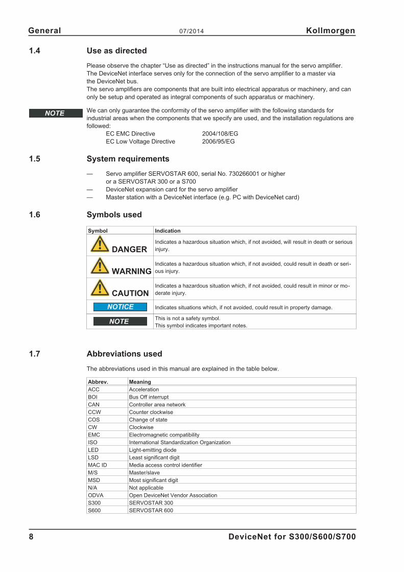
1.6 Symbols used
Symbol Indication
DANGERIndicates a hazardous situation which, if not avoided, will result in death or serious
injury.
WARNINGIndicates a hazardous situation which, if not avoided, could result in death or seri-
ous injury.
CAUTIONIndicates a hazardous situation which, if not avoided, could result in minor or mo-
derate injury.
Indicates situations which, if not avoided, could result in property damage.
This is not a safety symbol.
This symbol indicates important notes.
1.7 Abbreviations used
The abbreviations used in this manual are explained in the table below.
Abbrev. Meaning
ACC Acceleration
BOI Bus Off interrupt
CAN Controller area network
CCW Counter clockwise
COS Change of state
CW Clockwise
EMC Electromagnetic compatibility
ISO International Standardization Organization
LED Light-emitting diode
LSD Least significant digit
MAC ID Media access control identifier
M/S Master/slave
MSD Most significant digit
N/A Not applicable
ODVA Open DeviceNet Vendor Association
S300 SERVOSTAR 300
S600 SERVOSTAR 600
8 DeviceNet for S300/S600/S700
General 07/2014 Kollmorgen

1.8 Application of this manual
Specific examples for individual chapters can be found in the appendix of this manual.
1.9 Basic features implemented through DeviceNet
When working with the position controller that is integrated in the digital servo amplifiers, the follow-
ing functions are available:
Setup and general functions:
— homing, set reference point
— jogging, with a variable speed
— provision of a digital setpoint for speed and torque control
Positioning functions:
— execution of a motion task from the motion block memory of the servo amplifier
— execution of a direct motion task
— absolute trajectory
Data transfer functions:
— transmit a motion task to the motion block memory of the servo amplifier
A motion task consists of the following elements:
» position setpoint (absolute task) or path setpoint (relative task)
» speed setpoint
» acceleration time, braking time, rate-of-change/jolt limiting (in preparation)
» type of motion task (absolute/relative)
» number of a following task (with or without pause)
— Transmit a non-motion task to the motion block memory of the servo amplifier
In addition to motion tasks, the following task types can be modified through DeviceNet:
— modify attribute
— wait until parameter = value
— branch if greater than/less than
— decrement counter
— delay
— read a motion task from the motion block memory of the servo amplifier
— read actual values
— read the error register
— read the status register
— read/write configuration and control parameters
— read actual values from analog and digital inputs
— write control values to analog and digital outputs
Transmission rate and procedure
— bus connection and bus medium: CAN-standard ISO 11898 (CAN high-speed)
— transmission rate: 125, 250, 500 kbit/s
DeviceNet for S300/S600/S700 9
Kollmorgen 07/2014 General

This page has been deliberately left blank.
10 DeviceNet for S300/S600/S700
General 07/2014 Kollmorgen

2 Installation / Setup
2.1 Installation
WARNING
Install and wire up the equipment only while it is not electricallyconnected. Make sure that the machine control cabinet is safely isolated(lock-out, warning signs etc.).Never break any of the electrical connections to the servo amplifier whileit is live. This could result in destruction of the electronics.The individual supply voltages will not be switched on until setup iscarried out.Residual charges in the capacitors can still have dangerous levels severalminutes after switching off the supply voltage. Measure the voltage in theintermediate (DC bus link) circuit and wait until it has fallen below 60V.Power and control connections can still be live, even though the motor isnot rotating.
CAUTION
Electronic equipment is basically not failure-proof. The user isresponsible for ensuring that, in the event of a failure of the servoamplifier, the drive is set to a state that is safe for both machinery andpersonnel, for instance with the aid of a mechanical brake.Drives with servo amplifiers and DeviceNet expansion cards areremote-controlled machines. They can start to move at any time withoutprevious warning. Take appropriate measures to ensure that theoperating and service personnel is aware of this danger.Implement appropriate protective measures to ensure that anyunintended start-up of the machines cannot result in dangerous situationsfor personnel or machinery. Software limit-switches are not a substitutefor the hardware limit-switches in the machine.
Install the servo amplifier as described in the S300/S700 or S600 instructions manual. The wiring
for the analog setpoint input and the positioning interface, as shown in the wiring diagram in the
instructions manual, is not required.
Because of the internal representation of the position-control parameters, the position controller can
only be operated if the final limit speed of the drive at sinusoidal² commutation is not more than
7500 rpm. At trapezoidal commutation, the permitted maximum speed is 12000 rpm. All the data on
resolution, step size, positioning accuracy etc. refer to calculatory values. Non-linearities in the
mechanism (backlash, flexing, etc.) are not taken into account.
If the final limit speed of the motor has to be altered, then all the parameters that were previously
entered for position control and motion blocks must be adapted.
DeviceNet for S300/S600/S700 11
Kollmorgen 07/2014 Installation / Setup

2.1.1 Install the expansion card
To fit the DeviceNet expansion card into a servo amplifier, proceed as follows:
� Remove the cover of the option slot (refer to the instructions manual of the servo amplifier).
� Take care that no small items (such as screws) fall into the open option slot.
� Push the expansion card carefully into the guide rails that are provided, without twisting it.
� Press the expansion card firmly into the slot, until the front cover touches the fixing lugs. This
ensures that the connectors make good contact.
� Screw the screws on the front cover into the threads in the fixing lugs.
2.1.1.1 Combined Module / Network Status LED
State LED is To indicate:
Not powered / not online off
Device is not online.
- The device has not completed the Dup_MAC_ID test yet.
- The device may not be powered.
Operational AND
online, connectedgreen
The device is operating in a normal condition and the device is online
with connections in the established state.
- The device is allocated to a Master
Operational AND
online, not connected
or
Online AND
needs configuration
flashing
green
The device is operating in a normal condition and the device is online
with no connections in the established state.
- The device has passed the Dup_MAC_ID test, is online, but has
no established connections to other nodes.
- This device is not allocated to a master.
- Configuration missing, incomplete or incorrect.
Minor fault and/or
connection time outflashing red
Recoverable fault and/or one or more I/O Connections are in the
Timed–Out state.
Critical fault or
critical link failurered
- The device has an unrecoverable fault; may need replacing.
- Failed communication device. The device has detected an Error
that has rendered it incapable of communicating on the network
(e.g. Duplicate MAC ID, or Bus–off).
2.1.1.2 Front view
2.1.1.3 Connection technology
Cable selection, cable routing, shielding, bus connector, bus termination and transmission times are
all described in the “DeviceNet specification, volumes I, II", published by ODVA
12 DeviceNet for S300/S600/S700
Installation / Setup 07/2014 Kollmorgen

2.1.1.4 Bus cable
To meet ISO 898, a bus cable with a characteristic impedance of 120 � should be used. The maxi-
mum usable cable length for reliable communication decreases with increasing transmission speed.
As a guide, you can use the following values which we have measured, but they are not to be taken
as assured limits.
General characteristic Specification
Bit rates 125 kbit, 250 kbit, 500 kbit
Distance with larger
bus connections
500 meters at 125 kBaud
250 meters at 250 kBaud
100 meters at 500 kBaud
Number of nodes 64
Signal environment CAN
Modulation Basic bandwidth
Coupling medium DC-coupled differential transmit/receive operation
Isolation 500 V (option: optocoupler on the transceiver's node side)
Typical differential input imped-
ance (recessive state)
Shunt C = 5pF
Shunt R = 25K� (power on)
Min. differential input imped-
ance (recessive state)
Shunt C = 24pF + 36 pF/m of the permanently attached stub cable
Shunt R = 20K�
Absolute max.
voltage range
-25 V to +18 V (CAN_H, CAN_L)
The voltages for CAN_H and CAN_L refer to the ground pin of the trans-
ceiver. The voltage is higher than that on the V-terminal by the amount of the
forward voltage drop of the Schottky diode. This voltage drop must be < 0.6
V.
Grounding:
The DeviceNet network must only be grounded at one point, to avoid ground loops. The circuitry for
the physical layer in all devices are referenced to the V-bus signal. The ground connection is made
via the power supply for the bus system. The current flowing between V- and ground must not flow
through any device other than the power supply.
Bus topology:
The DeviceNet medium utilizes a linear bus topology. Termination resistors are required at each
end of the connecting cable. Stub cables are permitted up to a length of 6 meters, so that at least
one node can be connected.
Termination resistors:
DeviceNet requires a termination at each end of the connecting cable.
These resistors must meet the following requirements: 120 �, 1% metal-film, 1/4 W
Important: don't install the termination resistors at the end of stub cables, but on both ends of the
connectiing cable.
DeviceNet for S300/S600/S700 13
Kollmorgen 07/2014 Installation / Setup

Network Power:
Power taps for DeviceNet should have the following characteristics:
� Specified ratings for power supply and network currents (24V)
� Fuses or circuit breakers to limit current on the bus if current limiting in the power supply is in-
sufficient.
� 10 ft. maximum cable length from power supply to power tap
14 DeviceNet for S300/S600/S700
Installation / Setup 07/2014 Kollmorgen
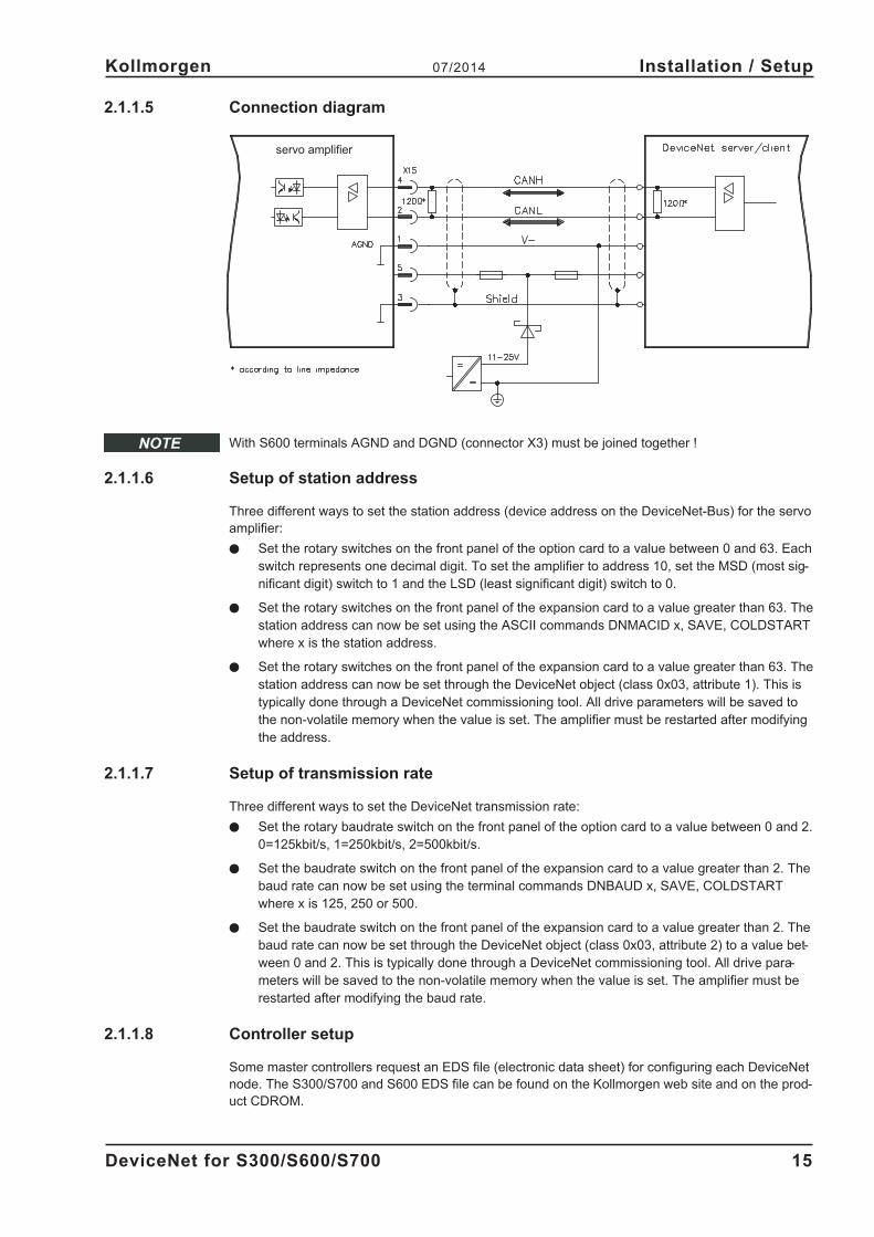
2.1.1.5 Connection diagram
With S600 terminals AGND and DGND (connector X3) must be joined together !
2.1.1.6 Setup of station address
Three different ways to set the station address (device address on the DeviceNet-Bus) for the servo
amplifier:
� Set the rotary switches on the front panel of the option card to a value between 0 and 63. Each
switch represents one decimal digit. To set the amplifier to address 10, set the MSD (most sig-
nificant digit) switch to 1 and the LSD (least significant digit) switch to 0.
� Set the rotary switches on the front panel of the expansion card to a value greater than 63. The
station address can now be set using the ASCII commands DNMACID x, SAVE, COLDSTART
where x is the station address.
� Set the rotary switches on the front panel of the expansion card to a value greater than 63. The
station address can now be set through the DeviceNet object (class 0x03, attribute 1). This is
typically done through a DeviceNet commissioning tool. All drive parameters will be saved to
the non-volatile memory when the value is set. The amplifier must be restarted after modifying
the address.
2.1.1.7 Setup of transmission rate
Three different ways to set the DeviceNet transmission rate:
� Set the rotary baudrate switch on the front panel of the option card to a value between 0 and 2.
0=125kbit/s, 1=250kbit/s, 2=500kbit/s.
� Set the baudrate switch on the front panel of the expansion card to a value greater than 2. The
baud rate can now be set using the terminal commands DNBAUD x, SAVE, COLDSTART
where x is 125, 250 or 500.
� Set the baudrate switch on the front panel of the expansion card to a value greater than 2. The
baud rate can now be set through the DeviceNet object (class 0x03, attribute 2) to a value bet-
ween 0 and 2. This is typically done through a DeviceNet commissioning tool. All drive para-
meters will be saved to the non-volatile memory when the value is set. The amplifier must be
restarted after modifying the baud rate.
2.1.1.8 Controller setup
Some master controllers request an EDS file (electronic data sheet) for configuring each DeviceNet
node. The S300/S700 and S600 EDS file can be found on the Kollmorgen web site and on the prod-
uct CDROM.
DeviceNet for S300/S600/S700 15
Kollmorgen 07/2014 Installation / Setup
servo amplifier
2.2 Setup
2.2.1 Guide to Setup
Only professional personnel with extensive knowledge of control and drive technology are allowed
to setup the servo amplifier.
Check assembly /
installation
Check that all the safety instructions in the instructions manual for the servo am-
plifier and this manual have been observed and implemented. Check the setting
for the station address (see p.15) and baud rate (see p.15).
Connect PC, start
setup softwareUse the amplifier's setup software to set the parameters.
Setup
the basic functions
Start up the basic functions of the servo amplifier and optimize the current, speed
and position controllers. This section is described in the online help of the setup
softwarel.
Save parameters When the parameters have been optimized, save them to the servo amplifier.
Start bus communica-
tion
Requirement: the software protocol must be implemented in the master.
Adjust the station address and the transmission rate of the servo amplifier to
match the master (see p.15).
Test communication
Connect to the servo amplifier with a master device.
Try viewing/modifying a parameter with explicit messaging
(Position Controller Object class 0x25, inst ance 0x01,
Target position attribute 0x06� terminal parameter O_P).
WARNING! Make sure that any unintended movement of the drive cannot
endanger machinery or personnel.
2.2.2 Error handling
Several parameters may be used to control DeviceNet error handling.
Bus off events are detected by the amplifier when there is a problem with the DeviceNet network.
Default behavior is to automatically reset communications whenever possible. To hold the amplifier
in a disconnected state when bus off errors are detected, set the BOI attribute of the DeviceNet
object to 0 (class 0x03, instance 1, attribute 3).
By default, the amplifier sets a node-guarding warning n04 when a communication timeout occurs
(the timeout behavior is typically controlled automatically by the PLC). To disable the node-guard-
ing warning, set the terminal parameter EXTWD=0.
This service is not supported in the S300/S700.
To view DeviceNet status information for debugging purposes, type DNDUMP in the setup software
terminal window.
2.2.3 Response to BUSOFF communication faults
The communication fault BUSOFF is directly monitored and signaled by Level 2 (CAN controller).
This message may have various causes.
Some examples:
— telegrams are transmitted, although there is no other CAN node connected
— CAN nodes have different transmission rates
— the bus cable is faulty
— faulty cable termination causes reflections on the cable.
The DeviceNet Object (class 0x03, attributes 3 and 4) determines the response to a BUSOFF con-
dition.
16 DeviceNet for S300/S600/S700
Installation / Setup 07/2014 Kollmorgen

3 DeviceNet Overview
The DeviceNet communication profile follows the ODVA standard Position Controller Device profile.
3.1 Functionality Chart
DeviceNet™ ODVA Requirements
Device Type Position Controller
Explicit Peer-to-Peer Messaging N
I/O Peer-to-Peer Messaging N
Baud Rates: 125, 250 and 500 kB
Polled Response Time <10ms
Explicit Response Time <50ms (except parameter object, <500ms)
Master/Scanner N
Configuration Consistency Value N
Faulted Node Recovery Y
I/O Slave Messaging
Bit Strobe N
Polling Y
Cyclic N
Change-of-State (COS) N
3.2 Overview of Explicit and Polled I/O (assembly) messages
The servo amplifiers with DeviceNet expansion card support two main types of DeviceNet commu-
nication: Explicit Messaging and Polled I/O Messaging.
Typically, Explicit Messaging is used to configure the amplifier and Polled I/O is used to control
movement. Most PLC’s will support both types of messaging simultaneously. The objects described
in sections 3.3 to 3.5 are all accessed though Explicit Messaging. Section 5.1 describes the use of
Polled I/O.
Explicit Messages allow you to access a single parameter value at a time. The desired parameter is
selected by specifying the class object number, instance number and attribute number in an explicit
message. Polled I/O messages combine many control and status bits into 8-byte command and
response messages. They are less versatile than explicit messages (only certain parameters are
accessible), but several control values may be changes within one message. For this reason,
Explicit Messaging is better for configuration and Polled I/O is better for motion control.
Most amplifier configuration is done within the Position Controller Object (class 0x25), which
encompasses most parameters necessary for motion control. Modify parameters in this object to
set the operational mode (torque, velocity, position) and configure motion. View parameters to read
the amplifier status words. Additional amplifier configuration may be done through the Parameter
Object (class 0x0F). This is a vendor-defined object which exposes vendor configuration parame-
ters. Any drive parameter with a DPR number (see the ascii.chm reference) less than 256 may be
accessed through the Parameter Object.
Motion sequences may be pre-programmed into the amplifier through the Command Block Object
(class 0x25). These blocks correspond to the SERVOSTAR motion tasking feature. Positioning
moves, time delays, and parameter modification blocks may be linked together to create a motion
block program that is stored in the amplifier. Once the stored block program has been configured, it
may be executed through either the Block Sequencer Object or with the Polled I/O Command Mes-
sage block number field and start block bit.
Polled I/O is used for most motion control. Control bits in a command message are used to enable
the amplifier, do a controlled stop of the motor, initiate motion, and initiate stored motion block pro-
grams. Command messages can also set the target position, target velocity, acceleration, decelera-
tion and torque parameters. Status bits in a response message display error states and the general
state of the amplifier. Response messages can also display the actual position, commanded posi-
tion, actual velocity and torque.
See the appendix for examples of actual use.
DeviceNet for S300/S600/S700 17
Kollmorgen 07/2014 DeviceNet Overview

3.3 Motion Objects with Explicit Messaging
The following DeviceNet objects are used to configure an amplifier and control motion.
3.3.1 Object: Parameter
Class Code 0x0F
Instance # 1 to 255
Description The parameter object gives direct access to amplifier configuration parameters
3.3.2 Object: Position Controller Supervisor
Class Code 0x24
Instance # 1
Description The position controller supervisor handles errors for the position controller.
3.3.3 Object: Position Controller
Class Code 0x25
Instance # 1
DescriptionThe position controller object is used to set the operating mode (torque, velocity, position),
configure motion profiles, and initiate movement.
3.3.4 Object: Block Sequencer
Class Code 0x26
Instance # 1
Description This object handles the execution of motion blocks or motion block chains
3.3.5 Object: Command Block
Class Code 0x27
Instance # 1 to 255
DescriptionEach instance of the command block object defines a specific motion block. These blocks can
be linked to other blocks to form a motion block chain.
18 DeviceNet for S300/S600/S700
DeviceNet Overview 07/2014 Kollmorgen
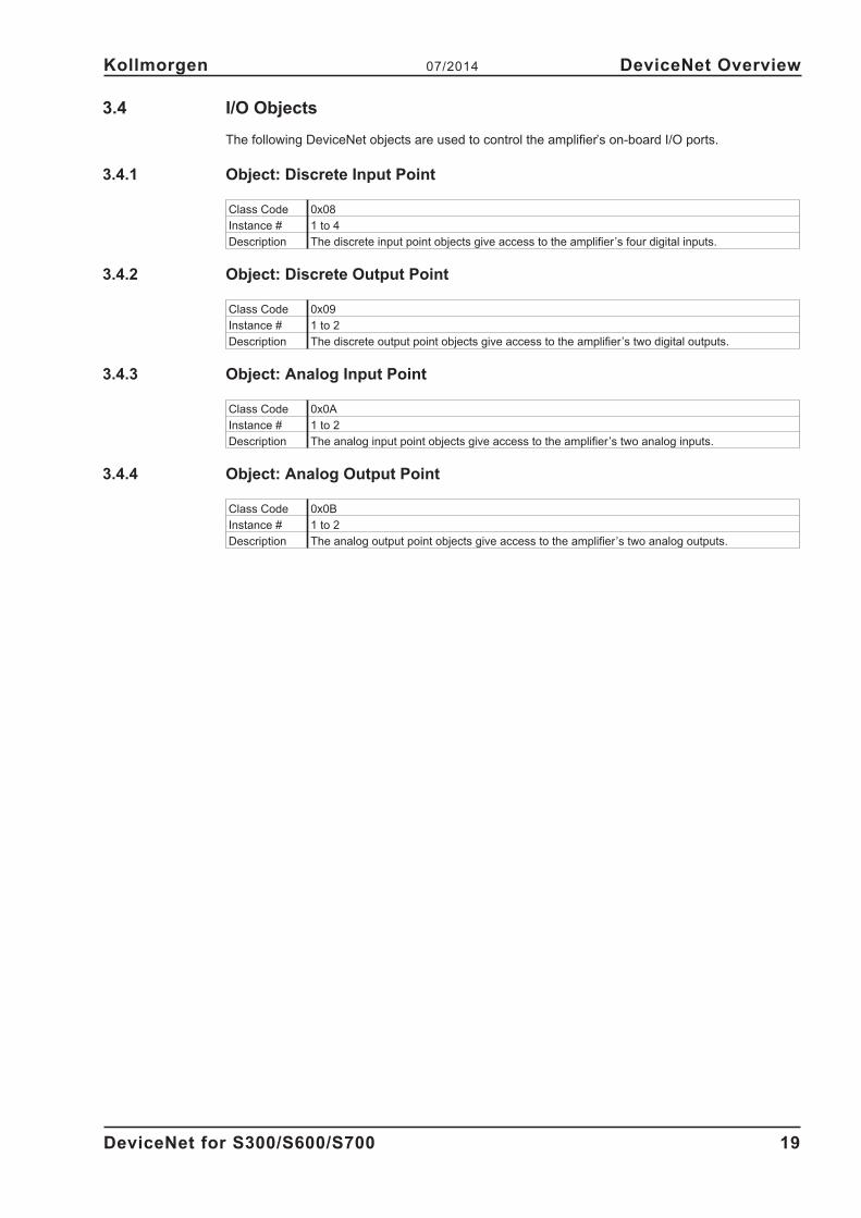
3.4 I/O Objects
The following DeviceNet objects are used to control the amplifier’s on-board I/O ports.
3.4.1 Object: Discrete Input Point
Class Code 0x08
Instance # 1 to 4
Description The discrete input point objects give access to the amplifier’s four digital inputs.
3.4.2 Object: Discrete Output Point
Class Code 0x09
Instance # 1 to 2
Description The discrete output point objects give access to the amplifier’s two digital outputs.
3.4.3 Object: Analog Input Point
Class Code 0x0A
Instance # 1 to 2
Description The analog input point objects give access to the amplifier’s two analog inputs.
3.4.4 Object: Analog Output Point
Class Code 0x0B
Instance # 1 to 2
Description The analog output point objects give access to the amplifier’s two analog outputs.
DeviceNet for S300/S600/S700 19
Kollmorgen 07/2014 DeviceNet Overview

3.5 Communication Objects
The following DeviceNet objects handle communication between the amplifier and a controller.
These are typically not accessed directly by a user’s PLC program.
3.5.1 Object: Identity
Class Code 0x01
Instance # 1
DescriptionThis object provides identification of any general information about the device. The Identity Ob-
ject is present in all DeviceNet products
3.5.2 Object: Message Router
Class Code 0x02
Instance # 1
DescriptionThis object provides a messaging connection point through which a client may address a servi-
ce to any object class or instance residing in the physical device.
3.5.3 Object: DeviceNet
Class Code 0x03
Instance # 1
Description
This object provides the configuration and status of a DeviceNet port. Each DeviceNet product
supports only one DeviceNet object per physical connection to the DeviceNet communication
link.
3.5.4 Object: Assembly
Class Code 0x04
Instance # 1
Description
This object binds attributes of multiple objects, which allows data to or from each object to be
sent or received over a single connection. Assembly objects can be used to bind input or out-
put data. An input produces data on the network and an output consumes data from the net-
work.
3.5.5 Object: Explicit Connection
Class Code 0x05
Instance # 1
Description This object manages the explicit messages.
3.5.6 Object: Polled I/O Connection
Class Code 0x07
Instance # 2
Description This object manages the I/O messages.
20 DeviceNet for S300/S600/S700
DeviceNet Overview 07/2014 Kollmorgen

3.6 Firmware Version
3.7 Supported Services
The DeviceNet objects support the following services:
Get_Single_Attribute (service code 0x0E)
Set_Single_Attribute (service code 0x10)
Reset (service code 0x05, class 0x01, instance 1, attribute 0 or 1, data length = 0)
Save (service code 0x16, class 0x0F, instance 1, attribute 0, data length = 0)
For additional information, we recommend that you review this entire document.
3.8 Data Types
The table below describes the data type, number of bits, minimum and maximum Range.
Data Type Number of Bits Minimum Value Maximum Value
Boolean 1 0 (False) 1 (True)
Short Integer 8 -128 127
Unsigned Short Integer 8 0 255
Integer 16 -32768 32767
Unsigned Integer 16 0 65535
Double Integer 32 -231 231 - 1
Unsigned Double Integer 32 0 232 - 1
3.9 Saving to Non-volatile Memory
Amplifier parameters are typically stored in RAM and only stored to non-volatile memory when a
SAVE is commanded through Explicit Messaging. A save operation can be initiated over DeviceNet
with either of two methods:
1) Save service of the Parameter Object. Transmit the following explicit message:
Service: 0x16
Class: 0x0F
Instance: 0x00
Attribute: 0x00
Data Length: 0
2) Save attribute of the Position Controller Object. Transmit the following explicit message:
Service: 0x10
Class: 0x25
Instance: 0x01
Attribute: 0x65
Data Length: 1
Data Value: 1
DeviceNet for S300/S600/S700 21
Kollmorgen 07/2014 DeviceNet Overview

This page has been deliberately left blank.
22 DeviceNet for S300/S600/S700
DeviceNet Overview 07/2014 Kollmorgen

4 Explicit messages
Typically, Explicit Messages are used to configure the amplifier and setup drive parameters. See
section 3.2 for more information.
4.1 Position Controller Supervisor Object (class 0x24)
The position controller supervisor handles errors for the position controller.
4.1.1 Error Codes
The amplifier returns one of the following codes when an error is generated while communicating
via Explicit Messaging.
Action Error Error Code
Set Attribute Not Settable 0x0E
Set or Get Attribute Not Supported 0x14
Set or Get Service Not Supported 0x08
Set or Get Class Not Supported 0x16
Set Value is Out of Range 0x09
4.1.1.1 Object State Conflicts – 0x0C
Three conditions could cause the amplifiers to return this error code. To proceed, check and clear
the condition.
Condition Solution
On hard or soft limit and then issuing a command to move in
the direction of the limitMove in opposite direction of the limit
Issuing a command not support in the current mode (i.e., trying
to do registration in velocity mode)
Change the mode to fit the application or is-
sue the proper command
Trying to enable a faulted amplifier Correct the fault before enabling the amplifier.
4.1.2 Supervisor Attributes
The following attributes are supported in the Position Controller Supervisor class. The instance
number always equals 1 in the class/instance/attribute mappings for the Position Controller Supervi-
sor.
4.1.2.1 Attribute 0x05: General Fault
Description
When active, this indicates that an amplifier-related failure has occurred, (Short Circuit,
Over-Voltage, etc.). It is not related to the FAULT input. It is reset when the fault condition is
removed.
Access Rule Get Default None
Data Type Boolean Non-Volatile N/A
Range1 = Fault condition exists
0 = No fault existsSee also Fault Code, ERRCODE (ASCII)
DeviceNet for S300/S600/S700 23
Kollmorgen 07/2014 Explicit messages
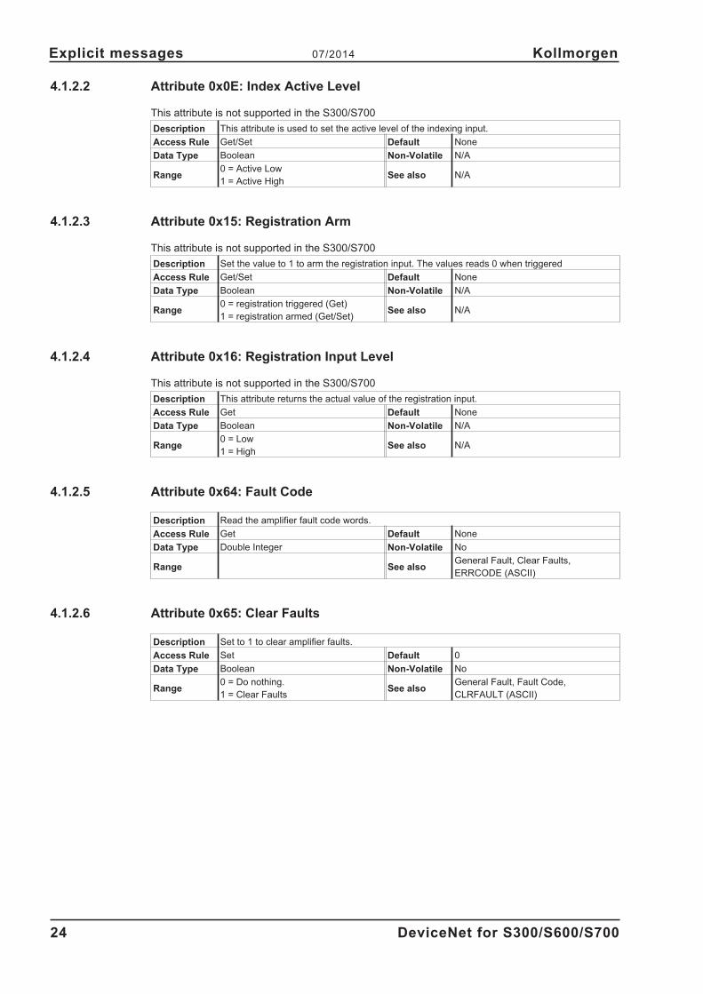
4.1.2.2 Attribute 0x0E: Index Active Level
This attribute is not supported in the S300/S700
Description This attribute is used to set the active level of the indexing input.
Access Rule Get/Set Default None
Data Type Boolean Non-Volatile N/A
Range0 = Active Low
1 = Active HighSee also N/A
4.1.2.3 Attribute 0x15: Registration Arm
This attribute is not supported in the S300/S700
Description Set the value to 1 to arm the registration input. The values reads 0 when triggered
Access Rule Get/Set Default None
Data Type Boolean Non-Volatile N/A
Range0 = registration triggered (Get)
1 = registration armed (Get/Set)See also N/A
4.1.2.4 Attribute 0x16: Registration Input Level
This attribute is not supported in the S300/S700
Description This attribute returns the actual value of the registration input.
Access Rule Get Default None
Data Type Boolean Non-Volatile N/A
Range0 = Low
1 = HighSee also N/A
4.1.2.5 Attribute 0x64: Fault Code
Description Read the amplifier fault code words.
Access Rule Get Default None
Data Type Double Integer Non-Volatile No
Range See alsoGeneral Fault, Clear Faults,
ERRCODE (ASCII)
4.1.2.6 Attribute 0x65: Clear Faults
Description Set to 1 to clear amplifier faults.
Access Rule Set Default 0
Data Type Boolean Non-Volatile No
Range0 = Do nothing.
1 = Clear FaultsSee also
General Fault, Fault Code,
CLRFAULT (ASCII)
24 DeviceNet for S300/S600/S700
Explicit messages 07/2014 Kollmorgen

4.2 Position Controller Object (class 0x25)
The position controller object is used to set the operating mode (torque, velocity, position), config-
ure a direct motion block or jog, and initiate movement.
4.2.1 Error Codes
The amplifier returns one of the following error codes when an error is generated while communicat-
ing via Explicit Messaging.
Action Error Error Code
Set Attribute Not Settable 0x0E
Set or Get Attribute Not Supported 0x14
Set or Get Service Not Supported 0x08
Set or Get Class Not Supported 0x16
Set Value is Out of Range 0x09
4.2.1.1 Object State Conflicts – 0x0C
Three conditions could cause the amplifiers to return this error code. To proceed, check and clear
the condition.
Conditin Solution
On hard or soft limit and then issuing a command to move in
the direction of the limitMove in opposite direction of the limit
Issuing a command not support in the current mode (i.e. trying
to do registration in velocity mode)
Change the mode to fit the application or is-
sue the proper command
Trying to enable a faulted amplifier Correct the fault before enabling the amplifier.
4.2.2 Position controller attributes
The following attributes are supported in the Position Controller class. The instance number always
equals 1 in the class/instance/attribute mappings for the Position Controller.
4.2.2.1 Attribute 0x01: Number of Attributes
Description The total number of attributes supported by the unit in the Position Controller Class.
Access Rule Get Default
Data Type Unsigned Short Integer Non-Volatile N/A
Range N/A See also Attribute List
4.2.2.2 Attribute 0x02: Attribute List
DescriptionReturns an array with a list of the attributes supported by this unit in the Position Controller
Class. The length of this list is specified in Number of Attributes.
Access Rule Get Default
Data Type Array of Unsigned Short Integer Non-Volatile N/A
Range Array size is defined by Attribute 1. See also Number of Attributes
DeviceNet for S300/S600/S700 25
Kollmorgen 07/2014 Explicit messages
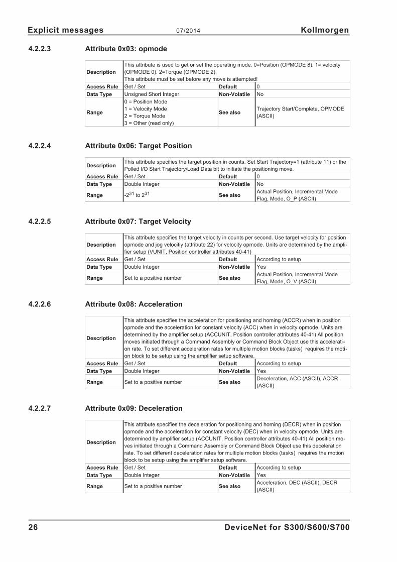
4.2.2.3 Attribute 0x03: opmode
Description
This attribute is used to get or set the operating mode. 0=Position (OPMODE 8). 1= velocity
(OPMODE 0). 2=Torque (OPMODE 2).
This attribute must be set before any move is attempted!
Access Rule Get / Set Default 0
Data Type Unsigned Short Integer Non-Volatile No
Range
0 = Position Mode
1 = Velocity Mode
2 = Torque Mode
3 = Other (read only)
See alsoTrajectory Start/Complete, OPMODE
(ASCII)
4.2.2.4 Attribute 0x06: Target Position
DescriptionThis attribute specifies the target position in counts. Set Start Trajectory=1 (attribute 11) or the
Polled I/O Start Trajectory/Load Data bit to initiate the positioning move.
Access Rule Get / Set Default 0
Data Type Double Integer Non-Volatile No
Range -231 to 231 See alsoActual Position, Incremental Mode
Flag, Mode, O_P (ASCII)
4.2.2.5 Attribute 0x07: Target Velocity
Description
This attribute specifies the target velocity in counts per second. Use target velocity for position
opmode and jog velocitiy (attribute 22) for velocity opmode. Units are determined by the ampli-
fier setup (VUNIT, Position controller attributes 40-41)
Access Rule Get / Set Default According to setup
Data Type Double Integer Non-Volatile Yes
Range Set to a positive number See alsoActual Position, Incremental Mode
Flag, Mode, O_V (ASCII)
4.2.2.6 Attribute 0x08: Acceleration
Description
This attribute specifies the acceleration for positioning and homing (ACCR) when in position
opmode and the acceleration for constant velocity (ACC) when in velocity opmode. Units are
determined by the amplifier setup (ACCUNIT, Position controller attributes 40-41) All position
moves initiated through a Command Assembly or Command Block Object use this accelerati-
on rate. To set different acceleration rates for multiple motion blocks (tasks) requires the moti-
on block to be setup using the amplifier setup software.
Access Rule Get / Set Default According to setup
Data Type Double Integer Non-Volatile Yes
Range Set to a positive number See alsoDeceleration, ACC (ASCII), ACCR
(ASCII)
4.2.2.7 Attribute 0x09: Deceleration
Description
This attribute specifies the deceleration for positioning and homing (DECR) when in position
opmode and the acceleration for constant velocity (DEC) when in velocity opmode. Units are
determined by amplifier setup (ACCUNIT, Position controller attributes 40-41) All position mo-
ves initiated through a Command Assembly or Command Block Object use this deceleration
rate. To set different deceleration rates for multiple motion blocks (tasks) requires the motion
block to be setup using the amplifier setup software.
Access Rule Get / Set Default According to setup
Data Type Double Integer Non-Volatile Yes
Range Set to a positive number See alsoAcceleration, DEC (ASCII), DECR
(ASCII)
26 DeviceNet for S300/S600/S700
Explicit messages 07/2014 Kollmorgen

4.2.2.8 Attribute 0x0A: Move Type
Description This bit is used to define the position value as either absolute or incremental in OpMode 8
Access Rule Get / Set Default 1
Data Type Boolean Non-Volatile No
Range0 = Absolute Position
1 = Incremental PositionSee also
Target Position, Trajectory Start/Com-
plete, O_C bit 0 (ASCII)
4.2.2.9 Attribute 0x0B: Trajectory Start/Complete
DescriptionSet high (1) to start a trajectory move. Reads high (1) while in motion and low (0) when motion
is complete
Access Rule Get / Set Default 0
Data Type Boolean Non-Volatile No
Range0 = Move Complete
1 = Start Trajectory (In Motion)See also Hard Stop, Smooth Stop
4.2.2.10 Attribute 0x0C: In Position
Description This flag, when set, indicates that the motor is within the deadband distance to the target
Access Rule Get Default 1
Data Type Boolean Non-Volatile N/A
Range0 = Not in position
1 = In positionSee also Trajectory Start/Complete, INPOS (ASCII)
4.2.2.11 Attribute 0x0D: Actual Position
DescriptionThe absolute position value equals the real position in counts. This is set to re-define the actu-
al position.
Access Rule Get / Set Default 0
Data Type Double Integer Non-Volatile No
Range -231 to 231 See alsoIncremental Mode Flag, Target Positi-
on, PFB (ASCII)
4.2.2.12 Attribute 0x0E: Actual Velocity
DescriptionThis attribute specifies the actual velocity. Units are determined by the amplifier setup (VUNIT,
position controller attriute 40-41)
Access Rule Get Default 0
Data Type Double Integer Non-Volatile No
Range Positive read value See also Target Velocity, PV (ASCII)
4.2.2.13 Attribute 0x11: Enable
DescriptionThis flag is used to control the enable output. Clearing this bit sets the enable output inactive
and the currently executing motion profile is aborted.
Access Rule Get / Set Default 0
Data Type Boolean Non-Volatile N/A
Range0 = Disable
1 = EnableSee also Actual Position, EN (ASCII)
DeviceNet for S300/S600/S700 27
Kollmorgen 07/2014 Explicit messages

4.2.2.14 Attribute 0x14: Smooth Stop
DescriptionThis bit is used to bring the motor to a controlled stop at the currently implemented decelerati-
on rate.
Access Rule Get / Set Default 0
Data Type Boolean Non-Volatile No
Range0 = No Action
1 = Perform Smooth StopSee also
Acceleration, Deceleration, Hard Stop,
Trajectory Start/Complete, STOP (ASCII)
4.2.2.15 Attribute 0x15: Hard Stop
Description This bit is used to bring the motor to an immediate stop
Access Rule Get / Set Default 0
Data Type Boolean Non-Volatile No
Range0 = No Action
1 = Perform Hard StopSee also
Smooth Stop, Trajectory Start/Com-
plete, DECSTOP (ASCII)
4.2.2.16 Attribute 0x16: Jog Velocity
Description
This attribute is used to set the target velocity in velocity mode. The Direction attribute is used
to select the direction of the velocity move. The Trajectory Start attribute is used to begin moti-
on. Units are determined by the amplifier setup (VUNIT, position controller attributes 40-41)
Access Rule Get / Set Default 0
Data Type Double Integer Non-Volatile Yes
Range Positive See alsoMode (velocity), Direction, Trajectory
Start/Complete, J (ASCII)
4.2.2.17 Attribute 0x17: Direction
DescriptionSet this bit to control the direction of the motor in velocity mode. Read this bit to get the actual
direction of motion.
Access Rule Get / Set Default 1
Data Type Boolean Non-Volatile No
Range0 = Negative Direction
1 = Positive DirectionSee also
Mode (velocity), Reference Direction,
J (ASCII)
4.2.2.18 Attribute 0x18: Reference direction
This attribute is not supported in the S300/S700
Description Defines positive direction (when viewed from the motor shaft side)
Access Rule Get / Set Default 0
Data Type Boolean Non-Volatile Yes
Range0 = Positive Clockwise Motion
1 = Positive Counter-Clockwise MotionSee also Direction, DIR (ASCII)
28 DeviceNet for S300/S600/S700
Explicit messages 07/2014 Kollmorgen
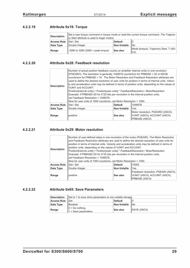
4.2.2.19 Attribute 0x19: Torque
DescriptionSet a new torque command in torque mode or read the current torque command. The Trajecto-
ry Start attribute is used to begin motion
Access Rule Get / Set Default 0
Data Type Double Integer Non-Volatile No
Range -3280 to 3280 (3280 = peak torque) See alsoMode (torque), Trajectory Start, T (AS-
CII)
4.2.2.20 Attribute 0x28: Feedback resolution
Description
Number of actual position feedback counts (or amplifier internal units) in one revolution
(PGEARO). The resolution is generally 1048576 counts/turn for PRBASE = 20 or 65536
counts/turn for PRBASE = 16. The Motor Resolution and Feedback Resolution attributes are
used to define the desired resolution of user units for position in terms of internal units. Veloci-
ty and acceleration units may be defined in terms of position units, depending on the values of
VUNIT and ACCUNIT.
Position[internal units] = Position[user units] * FeedbackResolution / MotorResolution
Example: if PRBASE=20 for 2^20 bits per revolution in the internal position units,
set Feedback Resolution = 1048576.
Now for user units of 1000 counts/rev, set Motor Resolution = 1000.
Access Rule Get / Set Default 1048576
Data Type Double Integer Non-Volatile Yes
Range positive See also
Motor resolution, PGEARO (ASCII),
VUNIT (ASCII), ACCUNIT (ASCII),
PRBASE (ASCII)
4.2.2.21 Attribute 0x29: Motor resolution
Description
Number of user-defined steps in one revolution of the motor (PGEARI). The Motor Resolution
and Feedback Resolution attributes are used to define the desired resolution of user units for
position in terms of internal units. Velocity and acceleration units may be defined in terms of
position units, depending on the values of VUNIT and ACCUNIT.
Position[internal units] = Position[user units] * FeedbackResolution / MotorResolution
Example: if PRBASE=20 for 2^20 bits per revolution in the internal position units,
set Feedback Resolution = 1048576.
Now for user units of 1000 counts/rev, set Motor Resolution = 1000.
Access Rule Get / Set Default 10000
Data Type Double Integer Non-Volatile Yes
Range positive See also
Feedback resolution, PGEARI (ASCII),
VUNIT (ASCII), ACCUNIT (ASCII),
PRBASE (ASCII)
4.2.2.22 Attribute 0x65: Save Parameters
Description Set to 1 to save drive parameters to non-volatile storage.
Access Rule Set Default 0
Data Type Boolean Non-Volatile No
Range0 = Do nothing.
1 = Save parameters.See also SAVE (ASCII)
DeviceNet for S300/S600/S700 29
Kollmorgen 07/2014 Explicit messages

4.2.2.23 Attribute 0x66: Amplifier Status
This attribute is not supported in the S300/S700. Read DRVSTAT using the Parameter Object
(class 0x0F) Non-Volatile 0x2D, Attribute 0x01.
DescriptionRead the amplifier status words. See the ASCII reference for a description of the status bits
(DRVSTAT).
Access Rule Get Default
Data Type Double Integer Non-Volatile No
Range See also DRVSTAT (ASCII)
4.2.2.24 Attribute 0x67: Trajectory Status
DescriptionRead the amplifier trajectory status words. See the ASCII reference for a description of the sta-
tus bits (TRJSTAT).
Access Rule Get Default
Data Type Double Integer Non-Volatile No
Range See also TRJSTAT (ASCII)
30 DeviceNet for S300/S600/S700
Explicit messages 07/2014 Kollmorgen

4.3 Parameter Object (class 0x0F)
Most drive parameters can be read and or written through the Parameter Object. This includes
many drive parameters also available through the Position Controller (class 0x25), Block Sequencer
(class 0x26), and Command Block Object (class 0x27). The Parameter Object, which gives direct
access to amplifier configuration parameters is a vendor-defined object.
In an explicit message to the parameter object, the instance number corresponds to the DPR num-
ber for the desired parameter. This DPR number may be found in the ascii.chm command refer-
ence. Only parameters 1-254 can be directly accessed with the instance number, since the instance
field is only 1 byte. Instance 255 is a special instance which means ‘use the Parameter Number
attribute’. See section 4.3.2.4 for documentation for accessing parameters 255 and higher.
The data length for Set Value commands can be determined from the ‘Data Type Bus/DPR’ field of
ascii.chm. Float types are scaled by 1000 to get an integer value.
Amplifier commands such as Jog, Home, and Save are executed by sending a Set Value command
with a data length of 1 and a value of 1. Reading the value or setting the value to 0 will not execute
the process.
For example, send the following explicit message to initiate homing (Move Home = MH,
DPR/instance = 141):
[class=0x0F, instance=141, attribute=0x01, data length=1, data value=0x01].
4.3.1 Error Codes
The amplifier returns one of the following error codes when an error is generated while communicat-
ing via Explicit Messaging.
Action Error Error Code
Set Attribute Not Settable 0x0E
Set or Get Attribute Not Supported 0x14
Set or Get Service Not Supported 0x08
Set or Get Class Not Supported 0x16
Set Value is Out of Range 0x09
4.3.2 Parameter Attributes
These are attributes supported by the unit in the Parameter Object Class.
4.3.2.1 Attribute 0x01: Parameter Value
Description
Directly access the parameter value. Check the command reference for the data type and
read/write access rule. Float types are multiplied by 1000 to get an integer value. Set the value
to 1 to execute an amplifier process (eg Move Home).
Access Ruledepends on the parameter and is given in
ascii.chm in the Type field.Default
Data Type
depends on the parameter and is given in
ascii.chm in the Format field. The byte
length is given by Data Length parameter.
Non-Volatile
Range See also Descriptor, Data Length, ascii.chm
4.3.2.2 Attribute 0x04: Descriptor
Description The descriptor will be 0x00 for read/write parameters and 0x10 for read-only parameters
Access Rule Get Default
Data Type Unsigned Short Integer Non-Volatile
Range See also
DeviceNet for S300/S600/S700 31
Kollmorgen 07/2014 Explicit messages
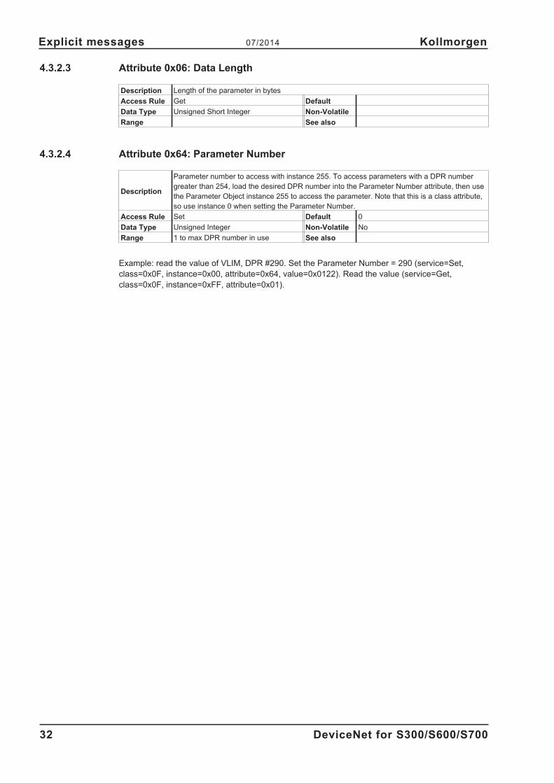
4.3.2.3 Attribute 0x06: Data Length
Description Length of the parameter in bytes
Access Rule Get Default
Data Type Unsigned Short Integer Non-Volatile
Range See also
4.3.2.4 Attribute 0x64: Parameter Number
Description
Parameter number to access with instance 255. To access parameters with a DPR number
greater than 254, load the desired DPR number into the Parameter Number attribute, then use
the Parameter Object instance 255 to access the parameter. Note that this is a class attribute,
so use instance 0 when setting the Parameter Number.
Access Rule Set Default 0
Data Type Unsigned Integer Non-Volatile No
Range 1 to max DPR number in use See also
Example: read the value of VLIM, DPR #290. Set the Parameter Number = 290 (service=Set,
class=0x0F, instance=0x00, attribute=0x64, value=0x0122). Read the value (service=Get,
class=0x0F, instance=0xFF, attribute=0x01).
32 DeviceNet for S300/S600/S700
Explicit messages 07/2014 Kollmorgen

4.4 Block Sequencer Object (class 0x26)
This object handles the execution of Motion Blocks or Motion Block chains. Motion sequences may
be pre-programmed into the amplifier through the Command Block Object (class 0x27). These
blocks correspond to the servo amplifier motion tasking feature. Positioning moves, time delays,
and parameter modification blocks may be linked together to create a motion block program that is
stored in the amplifier. Once the stored block program has been configured, it may be executed
through either the Block Sequencer Object or with the Polled I/O Command Message block number
field and start block bit.
4.4.1 Attribute 0x01: Block
DescriptionThis value defines the starting Command Block instance number to execute. The block num-
ber corresponds to the number in a MOVE [block number] command
Access Rule Get / Set Default N/A
Data Type Unsigned Short Integer Non-Volatile N/A
Range 1 to 255 See also Block Execute, MOVE (ASCII)
4.4.2 Attribute 0x02: Block Execute
DescriptionExecutes the starting command block defined by Attribute 1. This corresponds to a MOVE
command
Access Rule Get / Set Default 0
Data Type Boolean Non-Volatile N/A
Range
0 = Clear or Complete
1 = Execute Block (set) / Block Execu-
ting (get)
See also Block, Block Fault, MOVE (ASCII)
4.4.3 Attribute 0x03: Current Block
DescriptionThis attribute returns the command block instance number of the currently-executing block.
Reads 0 while homing.
Access Rule Get Default N/A
Data Type Unsigned Short Integer Non-Volatile N/A
Range 1 to 255 See alsoBlock, Block Execute, TASKNUM (AS-
CII)
4.4.4 Attribute 0x04: Block Fault
DescriptionSet when a block error occurs. When a block fault error occurs, block execution stops. This bit
is reset when the block fault code (5) is read.
Access Rule Get Default 0
Data Type Boolean Non-Volatile
Range0 = No Block Faults
1 = Block Fault OccurredSee also Block Execute, Block Fault Code
DeviceNet for S300/S600/S700 33
Kollmorgen 07/2014 Explicit messages
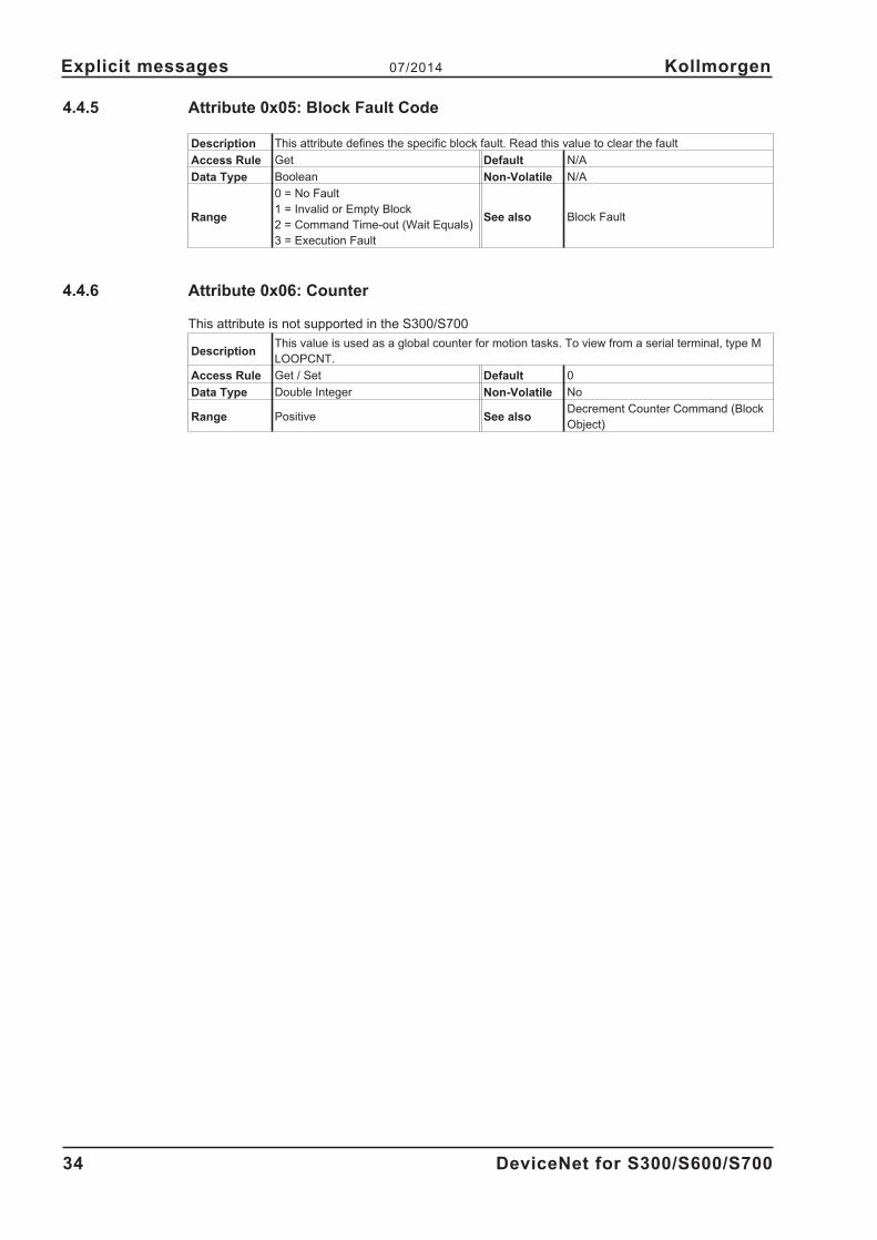
4.4.5 Attribute 0x05: Block Fault Code
Description This attribute defines the specific block fault. Read this value to clear the fault
Access Rule Get Default N/A
Data Type Boolean Non-Volatile N/A
Range
0 = No Fault
1 = Invalid or Empty Block
2 = Command Time-out (Wait Equals)
3 = Execution Fault
See also Block Fault
4.4.6 Attribute 0x06: Counter
This attribute is not supported in the S300/S700
DescriptionThis value is used as a global counter for motion tasks. To view from a serial terminal, type M
LOOPCNT.
Access Rule Get / Set Default 0
Data Type Double Integer Non-Volatile No
Range Positive See alsoDecrement Counter Command (Block
Object)
34 DeviceNet for S300/S600/S700
Explicit messages 07/2014 Kollmorgen
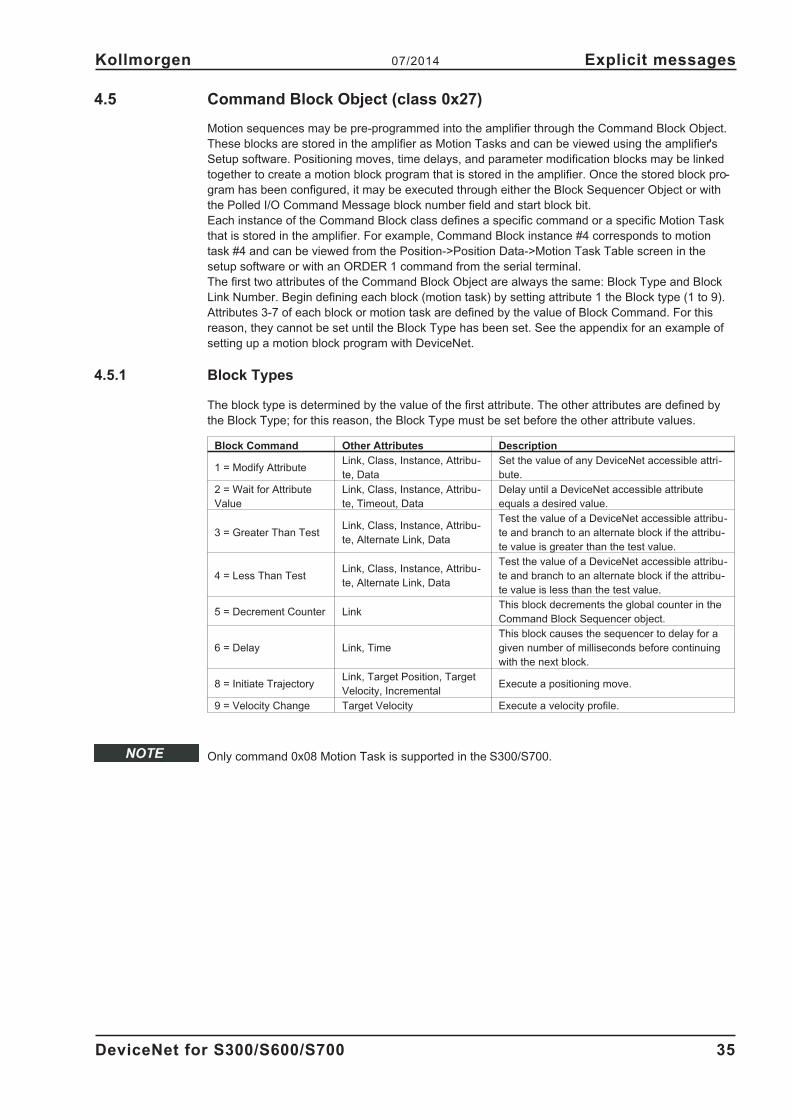
4.5 Command Block Object (class 0x27)
Motion sequences may be pre-programmed into the amplifier through the Command Block Object.
These blocks are stored in the amplifier as Motion Tasks and can be viewed using the amplifier's
Setup software. Positioning moves, time delays, and parameter modification blocks may be linked
together to create a motion block program that is stored in the amplifier. Once the stored block pro-
gram has been configured, it may be executed through either the Block Sequencer Object or with
the Polled I/O Command Message block number field and start block bit.
Each instance of the Command Block class defines a specific command or a specific Motion Task
that is stored in the amplifier. For example, Command Block instance #4 corresponds to motion
task #4 and can be viewed from the Position->Position Data->Motion Task Table screen in the
setup software or with an ORDER 1 command from the serial terminal.
The first two attributes of the Command Block Object are always the same: Block Type and Block
Link Number. Begin defining each block (motion task) by setting attribute 1 the Block type (1 to 9).
Attributes 3-7 of each block or motion task are defined by the value of Block Command. For this
reason, they cannot be set until the Block Type has been set. See the appendix for an example of
setting up a motion block program with DeviceNet.
4.5.1 Block Types
The block type is determined by the value of the first attribute. The other attributes are defined by
the Block Type; for this reason, the Block Type must be set before the other attribute values.
Block Command Other Attributes Description
1 = Modify AttributeLink, Class, Instance, Attribu-
te, Data
Set the value of any DeviceNet accessible attri-
bute.
2 = Wait for Attribute
Value
Link, Class, Instance, Attribu-
te, Timeout, Data
Delay until a DeviceNet accessible attribute
equals a desired value.
3 = Greater Than TestLink, Class, Instance, Attribu-
te, Alternate Link, Data
Test the value of a DeviceNet accessible attribu-
te and branch to an alternate block if the attribu-
te value is greater than the test value.
4 = Less Than TestLink, Class, Instance, Attribu-
te, Alternate Link, Data
Test the value of a DeviceNet accessible attribu-
te and branch to an alternate block if the attribu-
te value is less than the test value.
5 = Decrement Counter LinkThis block decrements the global counter in the
Command Block Sequencer object.
6 = Delay Link, Time
This block causes the sequencer to delay for a
given number of milliseconds before continuing
with the next block.
8 = Initiate TrajectoryLink, Target Position, Target
Velocity, IncrementalExecute a positioning move.
9 = Velocity Change Target Velocity Execute a velocity profile.
Only command 0x08 Motion Task is supported in the S300/S700.
DeviceNet for S300/S600/S700 35
Kollmorgen 07/2014 Explicit messages
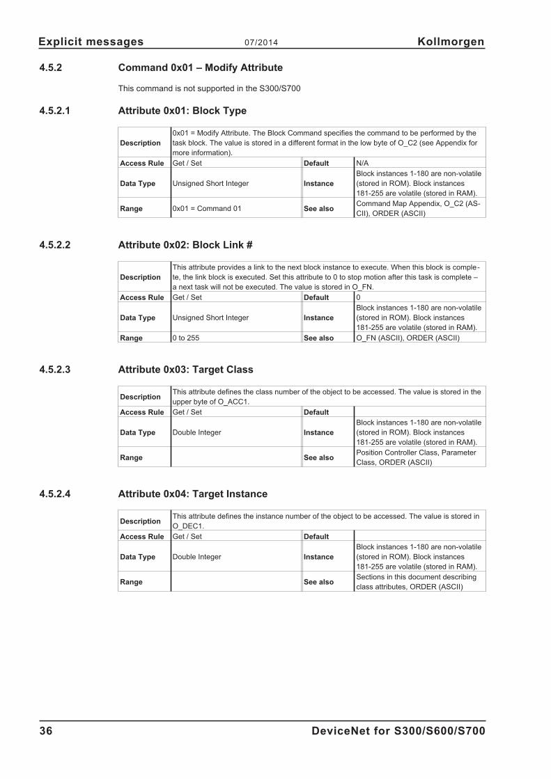
4.5.2 Command 0x01 – Modify Attribute
This command is not supported in the S300/S700
4.5.2.1 Attribute 0x01: Block Type
Description
0x01 = Modify Attribute. The Block Command specifies the command to be performed by the
task block. The value is stored in a different format in the low byte of O_C2 (see Appendix for
more information).
Access Rule Get / Set Default N/A
Data Type Unsigned Short Integer Instance
Block instances 1-180 are non-volatile
(stored in ROM). Block instances
181-255 are volatile (stored in RAM).
Range 0x01 = Command 01 See alsoCommand Map Appendix, O_C2 (AS-
CII), ORDER (ASCII)
4.5.2.2 Attribute 0x02: Block Link #
Description
This attribute provides a link to the next block instance to execute. When this block is comple-
te, the link block is executed. Set this attribute to 0 to stop motion after this task is complete –
a next task will not be executed. The value is stored in O_FN.
Access Rule Get / Set Default 0
Data Type Unsigned Short Integer Instance
Block instances 1-180 are non-volatile
(stored in ROM). Block instances
181-255 are volatile (stored in RAM).
Range 0 to 255 See also O_FN (ASCII), ORDER (ASCII)
4.5.2.3 Attribute 0x03: Target Class
DescriptionThis attribute defines the class number of the object to be accessed. The value is stored in the
upper byte of O_ACC1.
Access Rule Get / Set Default
Data Type Double Integer Instance
Block instances 1-180 are non-volatile
(stored in ROM). Block instances
181-255 are volatile (stored in RAM).
Range See alsoPosition Controller Class, Parameter
Class, ORDER (ASCII)
4.5.2.4 Attribute 0x04: Target Instance
DescriptionThis attribute defines the instance number of the object to be accessed. The value is stored in
O_DEC1.
Access Rule Get / Set Default
Data Type Double Integer Instance
Block instances 1-180 are non-volatile
(stored in ROM). Block instances
181-255 are volatile (stored in RAM).
Range See alsoSections in this document describing
class attributes, ORDER (ASCII)
36 DeviceNet for S300/S600/S700
Explicit messages 07/2014 Kollmorgen

4.5.2.5 Attribute 0x05: Attribute #
Description
This attribute defines the attribute number of the object to be accessed. The value is stored in
the lower byte of O_ACC1. The attribute referenced by the class, instance and attribute num-
bers in the command must be settable for this command to execute.
Access Rule Get / Set Default
Data Type Double Integer Instance
Block instances 1-180 are non-volatile
(stored in ROM). Block instances
181-255 are volatile (stored in RAM).
Range See alsoSections in this document describing
class attributes, ORDER (ASCII)
4.5.2.6 Attribute 0x06: Attribute Data
Description This is the new attribute data. The value is stored in O_P.
Access Rule Get / Set Default
Data Type Double Integer Instance
Block instances 1-180 are non-volatile
(stored in ROM). Block instances
181-255 are volatile (stored in RAM).
Range See also ORDER (ASCII)
4.5.3 Command 0x02 – Wait Until Equals
This command is not supported in the S300/S700
This command is used to wait until an attribute equals a desired value.
4.5.3.1 Attribute 0x01: Block Type
Description
0x02 = Wait Until Equals. The Block Command specifies the command to be performed by the
task block. The value is stored in a different format in the low byte of O_C2 (see the Command
Map Appendix for more information).
Access Rule Get / Set Default N/A
Data Type Unsigned Short Integer Instance
Block instances 1-180 are non-volatile
(stored in ROM). Block instances
181-255 are volatile (stored in RAM).
Range 0x02 = Command 02 See alsoCommand Map Appendix, O_C2 (AS-
CII), ORDER (ASCII)
4.5.3.2 Attribute 0x02: Block Link #
Description
This attribute provides a link to the next block instance to execute. When this block is comple-
te, the link block is executed. Set this attribute to 0 to stop motion after this task is complete –
a next task will not be executed. The value is stored in O_FN.
Access Rule Get / Set Default 0
Data Type Unsigned Short Integer Instance
Block instances 1-180 are non-volatile
(stored in ROM). Block instances
181-255 are volatile (stored in RAM).
Range 0 to 255 See also O_FN (ASCII), ORDER (ASCII)
DeviceNet for S300/S600/S700 37
Kollmorgen 07/2014 Explicit messages

4.5.3.3 Attribute 0x03: Target Class
DescriptionThis attribute defines the class number of the object to be accessed. The value is stored in the
upper byte of O_ACC1.
Access Rule Get / Set Default
Data Type Double Integer Instance
Block instances 1-180 are non-volatile
(stored in ROM). Block instances
181-255 are volatile (stored in RAM).
Range See alsoPosition Controller Class, Parameter
Class, ORDER (ASCII)
4.5.3.4 Attribute 0x04: Target Instance
DescriptionThis attribute defines the instance number of the object to be accessed. The value is stored in
O_DEC1.
Access Rule Get / Set Default
Data Type Double Integer Instance
Block instances 1-180 are non-volatile
(stored in ROM). Block instances
181-255 are volatile (stored in RAM).
Range See also ORDER (ASCII)
4.5.3.5 Attribute 0x05: Attribute #
Description
This attribute defines the attribute number of the object to be accessed. The value is stored in
the lower byte of O_ACC1. The attribute referenced by the class, instance and attribute num-
bers in the command must be settable for this command to execute.
Access Rule Get / Set Default
Data Type Double Integer Instance
Block instances 1-180 are non-volatile
(stored in ROM). Block instances
181-255 are volatile (stored in RAM).
Range See alsoSections in this document describing
class attributes, ORDER (ASCII)
4.5.3.6 Attribute 0x06: Timeout
DescriptionMaximum time in ms to wait for the parameter to equal the desired value. A fault is issued if
the timer expires. If set to 0, motion tasking will wait without faulting. Stored in O_FT
Access Rule Get / Set Default
Data Type Double Integer Instance
Block instances 1-180 are non-volatile
(stored in ROM). Block instances
181-255 are volatile (stored in RAM).
Range See also O_FT (ASCII), ORDER (ASCII)
4.5.3.7 Attribute 0x07: Compare Data
DescriptionThe attribute is compared to this value. If they are equal, motion will continue; otherwise, the
amplifier will wait. The value is stored in O_P.
Access Rule Get / Set Default
Data Type Dependent on Attribute # Instance
Block instances 1-180 are non-volatile
(stored in ROM). Block instances
181-255 are volatile (stored in RAM).
Range See also ORDER (ASCII)
38 DeviceNet for S300/S600/S700
Explicit messages 07/2014 Kollmorgen

4.5.4 Command 0x03 – Greater Than Test
This command is not supported in the S300/S700
This command is used for conditional linking or branching in a linked chain of commands. When the
block is executed, it will test the value of a DeviceNet accessible attribute and branch to an alter-
nate block if the attribute value is greater than the test value.
4.5.4.1 Attribute 0x01: Block Type
Description
0x03 = Greater Than Test. The Block Command specifies the command to be performed by
the task block. The value is stored in a different format in the low byte of O_C2 (see the Com-
mand Map Appendix for more information).
Access Rule Get / Set Default N/A
Data Type Unsigned Short Integer Instance
Block instances 1-180 are non-volatile
(stored in ROM). Block instances
181-255 are volatile (stored in RAM)
Range 0x03= Command 03 See alsoCommand Map Appendix, O_C2 (AS-
CII), ORDER (ASCII)
4.5.4.2 Attribute 0x02: Block Link #
Description
Description This attribute provides a link to the next block instance to execute. When this block
is complete, the link block is executed. Set this attribute to 0 to stop motion after this task is
complete – a next task will not be executed. The value is stored in O_FN.
Access Rule Get / Set Default 0
Data Type Unsigned Short Integer Instance
Block instances 1-180 are non-volatile
(stored in ROM). Block instances
181-255 are volatile (stored in RAM)
Range 0 to 255 See also O_FN (ASCII), ORDER (ASCII)
4.5.4.3 Attribute 0x03: Target Class
DescriptionThis attribute defines the class number of the object to be accessed. The value is stored in the
upper byte of O_ACC1.
Access Rule Get / Set Default
Data Type Double Integer Instance
Block instances 1-180 are non-volatile
(stored in ROM). Block instances
181-255 are volatile (stored in RAM)
Range See alsoPosition Controller Class, Parameter
Class, ORDER (ASCII)
4.5.4.4 Attribute 0x04: Target Instance
DescriptionThis attribute defines the instance number of the object to be accessed. The value is stored in
O_DEC1.
Access Rule Get / Set Default
Data Type Double Integer Instance
Block instances 1-180 are non-volatile
(stored in ROM). Block instances
181-255 are volatile (stored in RAM)
Range See also ORDER (ASCII)
DeviceNet for S300/S600/S700 39
Kollmorgen 07/2014 Explicit messages

4.5.4.5 Attribute 0x05: Attribute #
Description
This attribute defines the attribute number of the object to be accessed. The value is stored in
the lower byte of O_ACC1. The attribute referenced by the class, instance and attribute num-
bers in the command must be settable for this command to execute.
Access Rule Get / Set Default
Data Type Double Integer Instance
Block instances 1-180 are non-volatile
(stored in ROM). Block instances
181-255 are volatile (stored in RAM)
Range See alsoSections in this document describing
class attributes, ORDER (ASCII)
4.5.4.6 Attribute 0x06: Compare Link #
DescriptionIf the attribute value is greater than the test value, branch to the block specified in this attribute
instead of the block specified in attribute 2. The value is stored in O_DEC2.
Access Rule Get / Set Default
Data Type Double Integer Instance
Block instances 1-180 are non-volatile
(stored in ROM). Block instances
181-255 are volatile (stored in RAM)
Range 1 to 255 See also ORDER (ASCII)
4.5.4.7 Attribute 0x07: Compare Data
Description
This attribute is the comparison data for the conditional test. If the test attribute’s value is grea-
ter than the compare data, the normal link (Attribute 2) is ignored and the next block executed
is the compare link block (Attribute 6).
Access Rule Get / Set Default
Data Type Dependent on Attribute # Instance
Block instances 1-180 are non-volatile
(stored in ROM). Block instances
181-255 are volatile (stored in RAM)
Range See also ORDER (ASCII)
40 DeviceNet for S300/S600/S700
Explicit messages 07/2014 Kollmorgen

4.5.5 Command 0x04 – Less Than Test
This command is not supported in the S300/S700
This command is used for conditional linking or branching in a linked chain of commands. When the
block is executed, it will test the value of a DeviceNet accessible attribute and branch to an alter-
nate block if the attribute value is less than the test value.
4.5.5.1 Attribute 0x01: Block Type
Description
0x04 = Less Than Test. The Block Command specifies the command to be performed by the
task block. The value is stored in a different format in the low byte of O_C2 (see the Command
Map Appendix for more information).
Access Rule Get / Set Default N/A
Data Type Unsigned Short Integer Instance
Block instances 1-180 are non-volatile
(stored in ROM). Block instances
181-255 are volatile (stored in RAM)
Range 0x04 = Command 04 See alsoCommand Map Appendix, O_C2 (AS-
CII), ORDER (ASCII)
4.5.5.2 Attribute 0x02: Block Link #
Description
This attribute provides a link to the next block instance to execute. When this block is comple-
te, the link block is executed. This value must be non-zero for the delay command. The value
is stored in O_FN
Access Rule Get / Set Default
Data Type Unsigned Short Integer Instance
Block instances 1-180 are non-volatile
(stored in ROM). Block instances
181-255 are volatile (stored in RAM)
Range 1 to 255 See also O_FN (ASCII), ORDER (ASCII)
4.5.5.3 Attribute 0x03: Target Class
DescriptionThis attribute defines the class number of the object to be accessed. The value is stored in the
upper byte of O_ACC1.
Access Rule Get / Set Default
Data Type Double Integer Instance
Block instances 1-180 are non-volatile
(stored in ROM). Block instances
181-255 are volatile (stored in RAM)
Range See alsoPosition Controller Class, Parameter
Class, ORDER (ASCII)
4.5.5.4 Attribute 0x04: Target Instance
DescriptionThis attribute defines the instance number of the object to be accessed. The value is stored in
O_DEC1.
Access Rule Get / Set Default
Data Type Double Integer Instance
Block instances 1-180 are non-volatile
(stored in ROM). Block instances
181-255 are volatile (stored in RAM)
Range See also ORDER (ASCII)
DeviceNet for S300/S600/S700 41
Kollmorgen 07/2014 Explicit messages

4.5.5.5 Attribute 0x05: Attribute #
Description
This attribute defines the attribute number of the object to be accessed. The value is stored in
the lower byte of O_ACC1. The attribute referenced by the class, instance and attribute num-
bers in the command must be settable for this command to execute.
Access Rule Get / Set Default
Data Type Double Integer Instance
Block instances 1-180 are non-volatile
(stored in ROM). Block instances
181-255 are volatile (stored in RAM)
Range See alsoSections in this document describing
class attributes, ORDER (ASCII)
4.5.5.6 Attribute 0x06: Compare Link #
DescriptionIf the attribute value is less than the test value, branch to the block specified in this attribute
instead of the block specified in attribute 2. The value is stored in O_DEC2.
Access Rule Get / Set Default
Data Type Double Integer Instance
Block instances 1-180 are non-volatile
(stored in ROM). Block instances
181-255 are volatile (stored in RAM)
Range 1 to 255 See also ORDER (ASCII)
4.5.5.7 Attribute 0x07: Compare Data
Description
This attribute is the comparison data for the conditional test. If the test attribute’s value is less
than the compare data, the normal link (Attribute 2) is ignored and the next block executed is
the compare link block (Attribute 6).
Access Rule Get / Set Default
Data Type Dependent on Attribute # Instance
Block instances 1-180 are non-volatile
(stored in ROM). Block instances
181-255 are volatile (stored in RAM)
Range See also ORDER (ASCII)
42 DeviceNet for S300/S600/S700
Explicit messages 07/2014 Kollmorgen
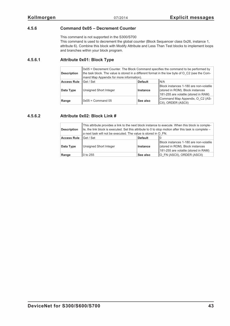
4.5.6 Command 0x05 – Decrement Counter
This command is not supported in the S300/S700
This command is used to decrement the global counter (Block Sequencer class 0x26, instance 1,
attribute 6). Combine this block with Modify Attribute and Less Than Test blocks to implement loops
and branches within your block program.
4.5.6.1 Attribute 0x01: Block Type
Description
0x05 = Decrement Counter. The Block Command specifies the command to be performed by
the task block. The value is stored in a different format in the low byte of O_C2 (see the Com-
mand Map Appendix for more information).
Access Rule Get / Set Default N/A
Data Type Unsigned Short Integer Instance
Block instances 1-180 are non-volatile
(stored in ROM). Block instances
181-255 are volatile (stored in RAM)
Range 0x05 = Command 05 See alsoCommand Map Appendix, O_C2 (AS-
CII), ORDER (ASCII)
4.5.6.2 Attribute 0x02: Block Link #
Description
This attribute provides a link to the next block instance to execute. When this block is comple-
te, the link block is executed. Set this attribute to 0 to stop motion after this task is complete –
a next task will not be executed. The value is stored in O_FN.
Access Rule Get / Set Default 0
Data Type Unsigned Short Integer Instance
Block instances 1-180 are non-volatile
(stored in ROM). Block instances
181-255 are volatile (stored in RAM)
Range 0 to 255 See also O_FN (ASCII), ORDER (ASCII)
DeviceNet for S300/S600/S700 43
Kollmorgen 07/2014 Explicit messages

4.5.7 Command 0x06 – Delay
This command is not supported in the S300/S700.
This command is used to delay a linked chain of commands.
4.5.7.1 Attribute 0x01: Block Type
Description
0x06 = Delay. The Block Command specifies the command to be performed by the task block.
The value is stored in the low byte of O_C2 (see the Command Map Appendix for more infor-
mation).
Access Rule Get / Set Default N/A
Data Type Unsigned Short Integer Instance
Block instances 1-180 are non-volatile
(stored in ROM). Block instances
181-255 are volatile (stored in RAM)
Range 0x06 = Command 06 See alsoCommand Map Appendix, O_C2 (AS-
CII), ORDER (ASCII)
4.5.7.2 Attribute 0x02: Block Link #
Description
This attribute provides a link to the next block instance to execute. When this block is comple-
te, the link block is executed. Set this attribute to 0 to stop motion after this task is complete –
a next task will not be executed. The value is stored in O_FN.
Access Rule Get / Set Default 0
Data Type Unsigned Short Integer Instance
Block instances 1-180 are non-volatile
(stored in ROM). Block instances
181-255 are volatile (stored in RAM)
Range 0 to 255 See also O_FN (ASCII), ORDER (ASCII)
4.5.7.3 Attribute 0x03: Delay
Description This attribute sets the delay in milliseconds. The value is stored in O_FT.
Access Rule Get / Set Default
Data Type Double Integer Instance
Block instances 1-180 are non-volatile
(stored in ROM). Block instances
181-255 are volatile (stored in RAM)
Range See also O_FT (ASCII), ORDER (ASCII)
44 DeviceNet for S300/S600/S700
Explicit messages 07/2014 Kollmorgen
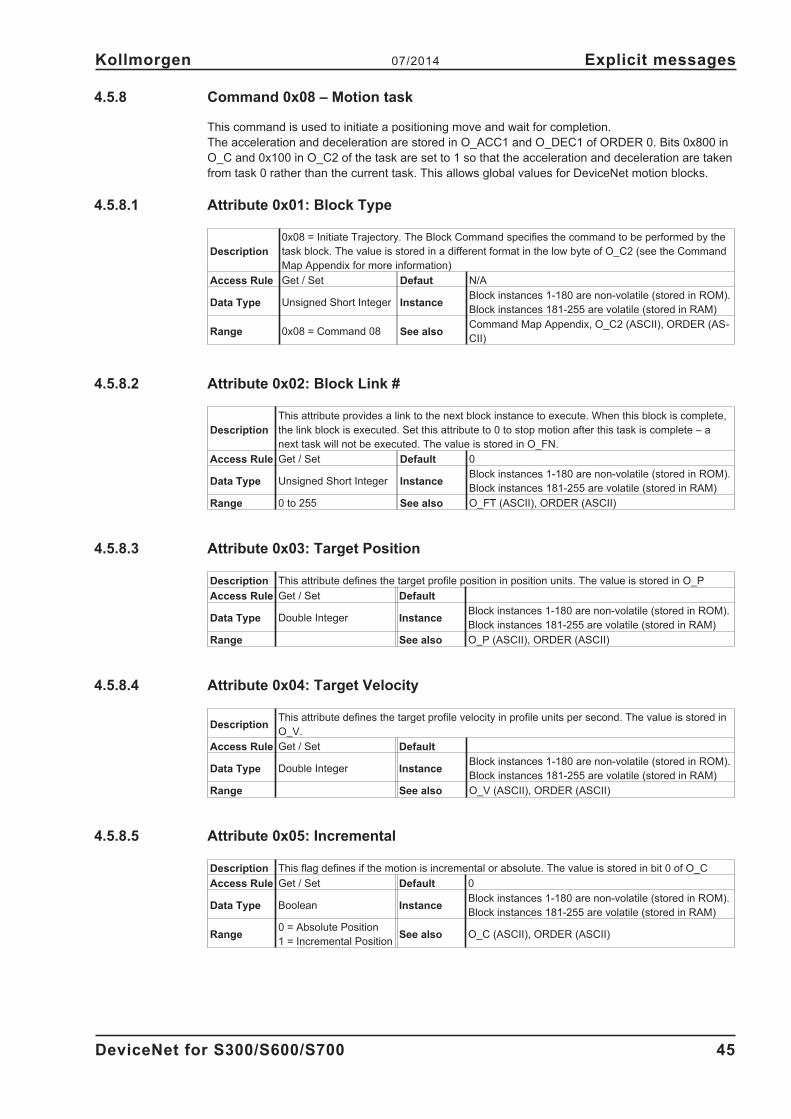
4.5.8 Command 0x08 – Motion task
This command is used to initiate a positioning move and wait for completion.
The acceleration and deceleration are stored in O_ACC1 and O_DEC1 of ORDER 0. Bits 0x800 in
O_C and 0x100 in O_C2 of the task are set to 1 so that the acceleration and deceleration are taken
from task 0 rather than the current task. This allows global values for DeviceNet motion blocks.
4.5.8.1 Attribute 0x01: Block Type
Description
0x08 = Initiate Trajectory. The Block Command specifies the command to be performed by the
task block. The value is stored in a different format in the low byte of O_C2 (see the Command
Map Appendix for more information)
Access Rule Get / Set Defaut N/A
Data Type Unsigned Short Integer InstanceBlock instances 1-180 are non-volatile (stored in ROM).
Block instances 181-255 are volatile (stored in RAM)
Range 0x08 = Command 08 See alsoCommand Map Appendix, O_C2 (ASCII), ORDER (AS-
CII)
4.5.8.2 Attribute 0x02: Block Link #
Description
This attribute provides a link to the next block instance to execute. When this block is complete,
the link block is executed. Set this attribute to 0 to stop motion after this task is complete – a
next task will not be executed. The value is stored in O_FN.
Access Rule Get / Set Default 0
Data Type Unsigned Short Integer InstanceBlock instances 1-180 are non-volatile (stored in ROM).
Block instances 181-255 are volatile (stored in RAM)
Range 0 to 255 See also O_FT (ASCII), ORDER (ASCII)
4.5.8.3 Attribute 0x03: Target Position
Description This attribute defines the target profile position in position units. The value is stored in O_P
Access Rule Get / Set Default
Data Type Double Integer InstanceBlock instances 1-180 are non-volatile (stored in ROM).
Block instances 181-255 are volatile (stored in RAM)
Range See also O_P (ASCII), ORDER (ASCII)
4.5.8.4 Attribute 0x04: Target Velocity
DescriptionThis attribute defines the target profile velocity in profile units per second. The value is stored in
O_V.
Access Rule Get / Set Default
Data Type Double Integer InstanceBlock instances 1-180 are non-volatile (stored in ROM).
Block instances 181-255 are volatile (stored in RAM)
Range See also O_V (ASCII), ORDER (ASCII)
4.5.8.5 Attribute 0x05: Incremental
Description This flag defines if the motion is incremental or absolute. The value is stored in bit 0 of O_C
Access Rule Get / Set Default 0
Data Type Boolean InstanceBlock instances 1-180 are non-volatile (stored in ROM).
Block instances 181-255 are volatile (stored in RAM)
Range0 = Absolute Position
1 = Incremental PositionSee also O_C (ASCII), ORDER (ASCII)
DeviceNet for S300/S600/S700 45
Kollmorgen 07/2014 Explicit messages

4.5.8.6 Attribute 0x64: O_C
This attribute is not supported in the S600.
Description
This attribute provides direct access to the O_C ORDER parameter. O_C is also automatically
modified when the Block Command (Command Block Object, Attribute 0x01) is set to Command
0x08 Motion Task.
Access Rule Get / Set Default N/A
Data Type Unsigned Long Integer InstanceBlock instances 1-180 are non-volatile (stored in ROM).
Block instances 181-255 are volatile (stored in RAM)
Range See also O_C (ASCII), ORDER (ASCII)
4.5.8.7 Attribute 0x65: O_ACC
This attribute is not supported in the S600.
Description
This attribute provides direct access to the O_ACC ORDER parameter. O_ACC is also automa-
tically modified when the Block Command (Command Block Object, Attribute 0x01) is set to
Command 0x08 Motion Task.
Access Rule Get / Set Default N/A
Data Type Unsigned Long Integer InstanceBlock instances 1-180 are non-volatile (stored in ROM).
Block instances 181-255 are volatile (stored in RAM)
Range See also O_ACC (ASCII), ORDER (ASCII)
4.5.8.8 Attribute 0x66: O_DEC
This attribute is not supported in the S600.
Description
This attribute provides direct access to the O_DEC ORDER parameter. O_DEC is also automa-
tically modified when the Block Command (Command Block Object, Attribute 0x01) is set to
Command 0x08 Motion Task.
Access Rule Get / Set Default N/A
Data Type Unsigned Long Integer InstanceBlock instances 1-180 are non-volatile (stored in ROM).
Block instances 181-255 are volatile (stored in RAM)
Range See also O_DEC (ASCII), ORDER (ASCII)
4.5.8.9 Attribute 0x67: O_TAB
This attribute is not supported in the S600.
Description
This attribute provides direct access to the O_TAB ORDER parameter. O_TAB is also automati-
cally modified when the Block Command (Command Block Object, Attribute 0x01) is set to
Command 0x08 Motion Task.
Access Rule Get / Set Default N/A
Data Type Unsigned Long Integer InstanceBlock instances 1-180 are non-volatile (stored in ROM).
Block instances 181-255 are volatile (stored in RAM)
Range See also O_TAB (ASCII), ORDER (ASCII)
4.5.8.10 Attribute 0x68: O_FT
This attribute is not supported in the S600.
Description
This attribute provides direct access to the O_FT ORDER parameter. O_FT is also automatical-
ly modified when the Block Command (Command Block Object, Attribute 0x01) is set to Com-
mand 0x08 Motion Task.
Access Rule Get / Set Default N/A
Data Type Unsigned Long Integer InstanceBlock instances 1-180 are non-volatile (stored in ROM).
Block instances 181-255 are volatile (stored in RAM)
Range See also O_FT (ASCII), ORDER (ASCII)
46 DeviceNet for S300/S600/S700
Explicit messages 07/2014 Kollmorgen
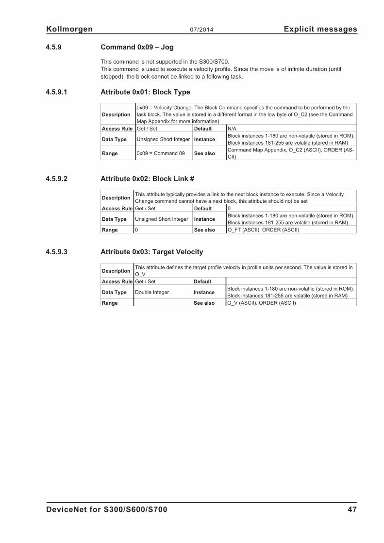
4.5.9 Command 0x09 – Jog
This command is not supported in the S300/S700.
This command is used to execute a velocity profile. Since the move is of infinite duration (until
stopped), the block cannot be linked to a following task.
4.5.9.1 Attribute 0x01: Block Type
Description
0x09 = Velocity Change. The Block Command specifies the command to be performed by the
task block. The value is stored in a different format in the low byte of O_C2 (see the Command
Map Appendix for more information)
Access Rule Get / Set Default N/A
Data Type Unsigned Short Integer InstanceBlock instances 1-180 are non-volatile (stored in ROM).
Block instances 181-255 are volatile (stored in RAM)
Range 0x09 = Command 09 See alsoCommand Map Appendix, O_C2 (ASCII), ORDER (AS-
CII)
4.5.9.2 Attribute 0x02: Block Link #
DescriptionThis attribute typically provides a link to the next block instance to execute. Since a Velocity
Change command cannot have a next block, this attribute should not be set
Access Rule Get / Set Default 0
Data Type Unsigned Short Integer InstanceBlock instances 1-180 are non-volatile (stored in ROM).
Block instances 181-255 are volatile (stored in RAM)
Range 0 See also O_FT (ASCII), ORDER (ASCII)
4.5.9.3 Attribute 0x03: Target Velocity
DescriptionThis attribute defines the target profile velocity in profile units per second. The value is stored in
O_V
Access Rule Get / Set Default
Data Type Double Integer InstanceBlock instances 1-180 are non-volatile (stored in ROM).
Block instances 181-255 are volatile (stored in RAM)
Range See also O_V (ASCII), ORDER (ASCII)
DeviceNet for S300/S600/S700 47
Kollmorgen 07/2014 Explicit messages
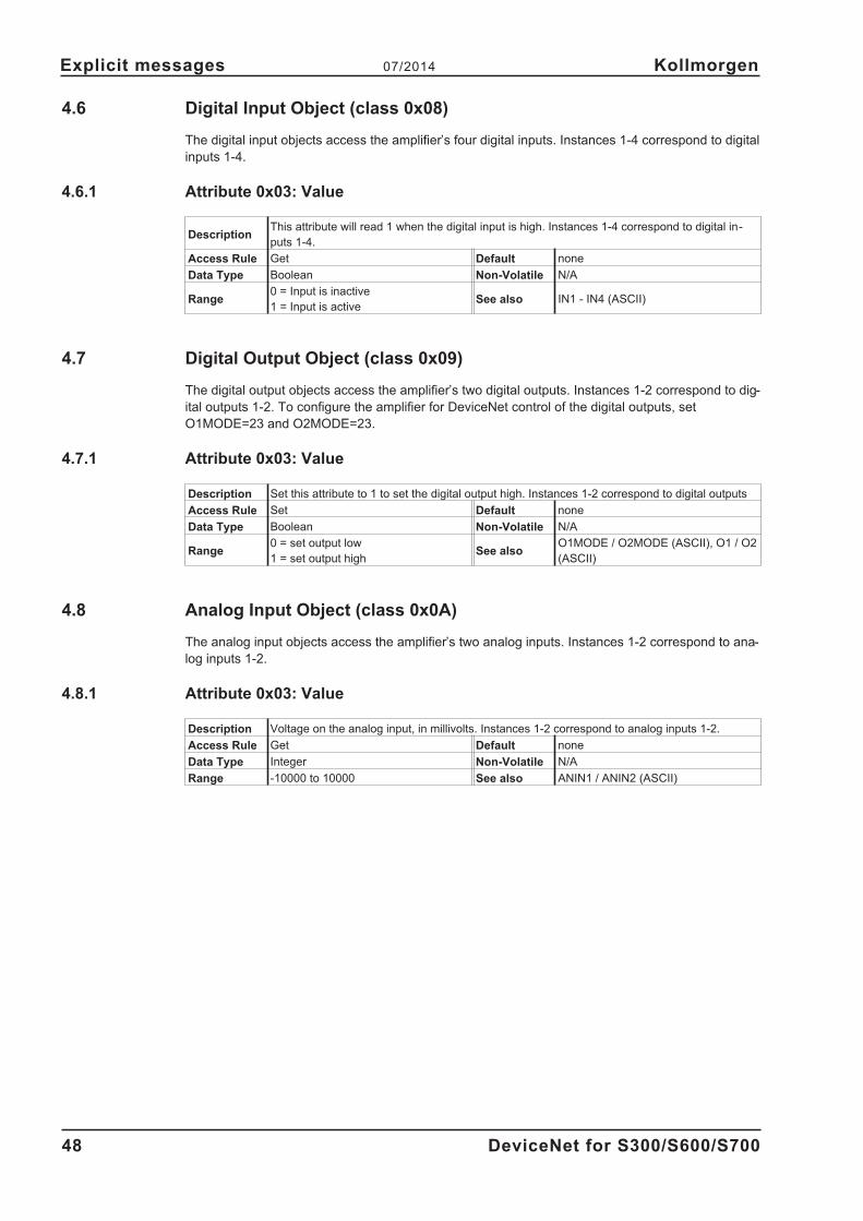
4.6 Digital Input Object (class 0x08)
The digital input objects access the amplifier’s four digital inputs. Instances 1-4 correspond to digital
inputs 1-4.
4.6.1 Attribute 0x03: Value
DescriptionThis attribute will read 1 when the digital input is high. Instances 1-4 correspond to digital in-
puts 1-4.
Access Rule Get Default none
Data Type Boolean Non-Volatile N/A
Range0 = Input is inactive
1 = Input is activeSee also IN1 - IN4 (ASCII)
4.7 Digital Output Object (class 0x09)
The digital output objects access the amplifier’s two digital outputs. Instances 1-2 correspond to dig-
ital outputs 1-2. To configure the amplifier for DeviceNet control of the digital outputs, set
O1MODE=23 and O2MODE=23.
4.7.1 Attribute 0x03: Value
Description Set this attribute to 1 to set the digital output high. Instances 1-2 correspond to digital outputs
Access Rule Set Default none
Data Type Boolean Non-Volatile N/A
Range0 = set output low
1 = set output highSee also
O1MODE / O2MODE (ASCII), O1 / O2
(ASCII)
4.8 Analog Input Object (class 0x0A)
The analog input objects access the amplifier’s two analog inputs. Instances 1-2 correspond to ana-
log inputs 1-2.
4.8.1 Attribute 0x03: Value
Description Voltage on the analog input, in millivolts. Instances 1-2 correspond to analog inputs 1-2.
Access Rule Get Default none
Data Type Integer Non-Volatile N/A
Range -10000 to 10000 See also ANIN1 / ANIN2 (ASCII)
48 DeviceNet for S300/S600/S700
Explicit messages 07/2014 Kollmorgen

4.9 Analog Output Object (class 0x0B)
This object is not supported in the S300/S700.
The analog output objects access the amplifier’s two analog outputs. Instances 1-2 correspond to
analog outputs 1-2. To configure the amplifier for DeviceNet control of the analog outputs, set
ANOUT1=6 and ANOUT2=6.
4.9.1 Attribute 0x03: Value
Description
Set to the desired output voltage in millivolts. To configure the amplifier for DeviceNet control
of the analog outputs, set ANOUT1=6 and ANOUT2=6. The value is stored in AN1TRIG /
AN2TRIG.
Access Rule Set Default none
Data Type Integer Non-Volatile N/A
Range -1000 to 10000 See alsoANOUT1 / ANOUT2 (ASCII),
AN1TRIG / AN2TRIG (ASCII)
4.10 Identity Object (class 0x01)
Identity Object 0x01
Object Class ID Description Get Set Value Limits
Attributes Open 1 Revision
2 Max instance
X None Supported 3 Number of Instances
4 Optional attributes list
5 Optional services list
6 Max Id of class attributes
7 Max Id of instance attributes
DeviceNet Services Parameter Options
Services Get_Attributes_All
Reset
X None Supported Get_Attribute_Single
Find_Next_Object_instance
Object Instance ID Description Get Set Value Limits
Attributes Open 1 Vendor X =(452)
2 Device type X =(16)
3 Product code X =(3)
4 Revision X =(1.1)
5 Status (bits supported) X
6 Serial number X
7 Product name X SERVOSTAR
8 State
9 Config. Consistency Value
10 Heartbeat Interval
DeviceNet Services Parameter Options
Services Get_Attributes_All
X Reset 0,1
X Get_Attribute_Single
Set_Attribute_Single
DeviceNet for S300/S600/S700 49
Kollmorgen 07/2014 Explicit messages

4.11 Message Router Object (class 0x02)
Message Router Object 0x02
Object Class ID Description Get Set Value Limits
Attributes Open 1 Revision
2 Max instance
X None Supported 3 Number of Instances
4 Optional attributes list
5 Optional services list
6 Max Id of class attributes
7 Max Id of instance attributes
DeviceNet Services Parameter Options
Services Get_Attributes_All
X None Supported Get_Attribute_Single
Object Instance ID Description Get Set Value Limits
Attributes Open 1 Object list
2 Maximum connections supported
X None Supported 3 Number of active connections
4 Active connections list
DeviceNet Services Parameter Options
Services Get_Attributes_All
Get_Attribute_Single
X None Supported Set_Attribute_Single
4.12 DeviceNet Object (class 0x03)
DeviceNet Object 0x03
Object Class ID Description Get Set Value Limits
Attributes Open 1 Revision X
2 Max instance
None Supported 3 Number of Instances
4 Optional attributes list
5 Optional services list
6 Max Id of class attributes
7 Max Id of instance attributes
DeviceNet Services Parameter Options
Services X Get_Attribute_Single
None Supported
Object Instance ID Description Get Set Value Limits
Attributes Open 1 MAC ID X
2 Baud rate X
None Supported 3 BOI X X
4 Bus-off counter X X
5 Allocation information X
6 MAC ID switch changed
7 Baud rate switch changed
8 MAC ID switch value X
9 Baud rate switch value X
DeviceNet Services Parameter Options
Services X Get_Attributes_All
X Set_Attribute_Single
None Supported X Allocate M/S connection set
X Release M/S connection set
50 DeviceNet for S300/S600/S700
Explicit messages 07/2014 Kollmorgen
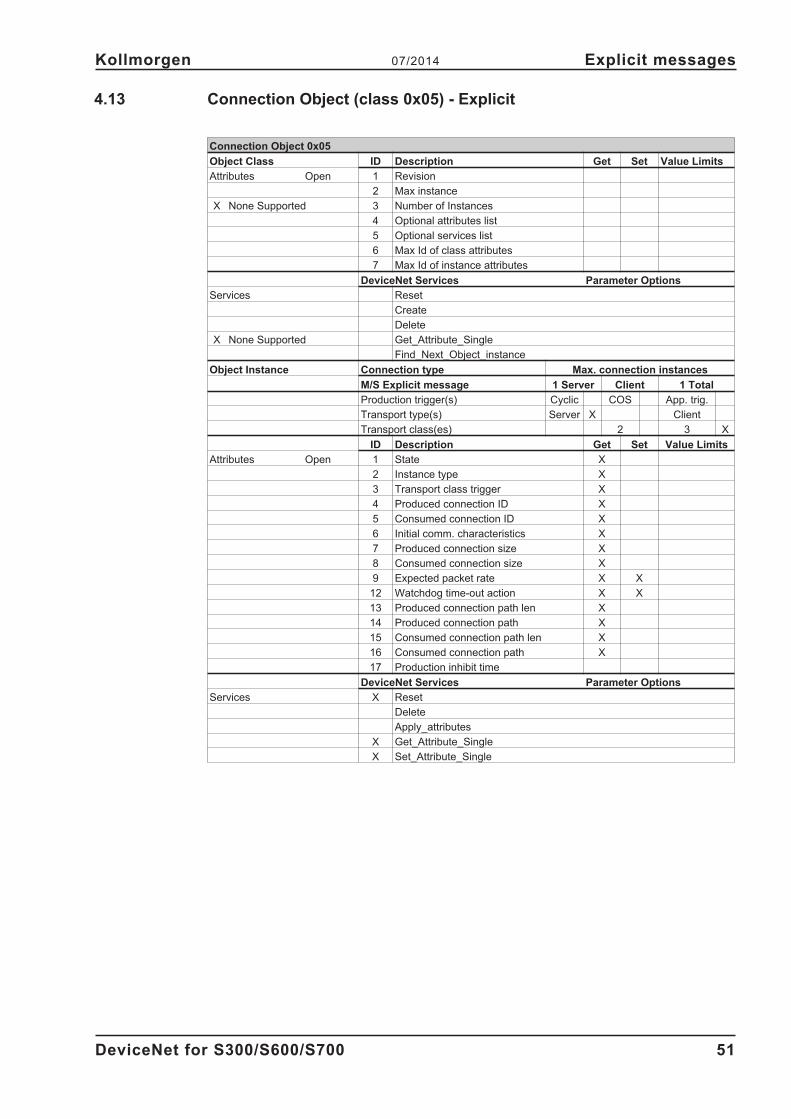
4.13 Connection Object (class 0x05) - Explicit
Connection Object 0x05
Object Class ID Description Get Set Value Limits
Attributes Open 1 Revision
2 Max instance
X None Supported 3 Number of Instances
4 Optional attributes list
5 Optional services list
6 Max Id of class attributes
7 Max Id of instance attributes
DeviceNet Services Parameter Options
Services Reset
Create
Delete
X None Supported Get_Attribute_Single
Find_Next_Object_instance
Object Instance Connection type Max. connection instances
M/S Explicit message 1 Server Client 1 Total
Production trigger(s) Cyclic COS App. trig.
Transport type(s) Server X Client
Transport class(es) 2 3 X
ID Description Get Set Value Limits
Attributes Open 1 State X
2 Instance type X
3 Transport class trigger X
4 Produced connection ID X
5 Consumed connection ID X
6 Initial comm. characteristics X
7 Produced connection size X
8 Consumed connection size X
9 Expected packet rate X X
12 Watchdog time-out action X X
13 Produced connection path len X
14 Produced connection path X
15 Consumed connection path len X
16 Consumed connection path X
17 Production inhibit time
DeviceNet Services Parameter Options
Services X Reset
Delete
Apply_attributes
X Get_Attribute_Single
X Set_Attribute_Single
DeviceNet for S300/S600/S700 51
Kollmorgen 07/2014 Explicit messages

4.14 Connection Object (class 0x05) - Polled I/O
Connection Object 0x05
Object Class ID Description Get Set Value Limits
Attributes Open 1 Revision
2 Max instance
X None Supported 3 Number of Instances
4 Optional attributes list
5 Optional services list
6 Max Id of class attributes
7 Max Id of instance attributes
DeviceNet Services Parameter Options
Services X Reset
Create
Delete
X None Supported Get_Attribute_Single
Find_Next_Object_instance
Object Instance Connection type Max. connection instances
M/S poll 1 Server Client 1 Total
Production trigger(s) Cyclic X COS App. trig.
Transport type(s) Server X Client
Transport class(es) 2 X 3
ID Description Get Set Value Limits
Attributes Open 1 State X
2 Instance type X
3 Transport class trigger X
4 Produced connection ID X
5 Consumed connection ID X
6 Initial comm. characteristics X
7 Produced connection size X
8 Consumed connection size X
9 Expected packet rate X X
12 Watchdog time-out action X X
13 Produced connection path len X
14 Produced connection path X
15 Consumed connection path len X
16 Consumed connection path X
17 Production inhibit time
DeviceNet Services Parameter Options
Services X Reset
Delete
Apply_attributes
X Get_Attribute_Single
X Set_Attribute_Single
52 DeviceNet for S300/S600/S700
Explicit messages 07/2014 Kollmorgen

5 Polled I/O messages
Typically, Polled I/O (Assembly) Messages are used for real-time data and motion control. See sec-
tion 3.2 for more information.
5.1 I/O Command Assemblies
Polled I/O Messaging is a method of transmitting a group of control bits and a data command and
receiving back a group of status bits and a data value response. This method of communication is
preferred, as explicit messaging can transmit only a single value at a time. Polled I/O and Explicit
Messaging may be used simultaneously for communications between the controller and the ampli-
fier. In this section, the format of each Command Assembly is defined and examples of each are
provided.
Command assemblies contain control bits which are defined the same for each type of command.
In addition to the control bits, a command assembly may be used to send one data command at a
time (target position, target velocity, acceleration, deceleration or torque). The command type is
specified in the Command Assembly Type field.
The amplifier will respond to each Command Assembly it receives by transmitting a Response
Assembly. The response assembly has status bits which are defined the same for each type of
response. In addition to status bits, a response assembly can transmit one data value at a time
(actual position, commanded position, actual velocity, actual torque or error code). The response
type is specified in the Response Assembly Type field of the command assembly. A command
assembly may contain both a Command Assembly Type and a Response Assembly Type to trans-
mit a command and request a response in the same assembly.
The command is ignored unless a valid command assembly type is specified in byte 2 (valid
command assembly types are 0 through 5).
Data outside the range of the attribute will result in an Error Response Assembly. This applies to all
Command Assemblies, except Assembly 5 (torque).
The amplifier must be homed before motion is begun in position mode. Failure to home the
amplifier will result in a an amplifier alarm that must be cleared before amplifier operation can
continue.
DeviceNet for S300/S600/S700 53
Kollmorgen 07/2014 Polled I/O messages
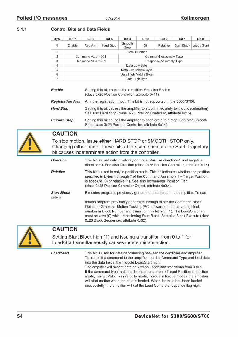
5.1.1 Control Bits and Data Fields
Byte Bit 7 Bit 6 Bit 5 Bit 4 Bit 3 Bit 2 Bit 1 Bit 0
0 Enable Reg Arm Hard StopSmooth
StopDir Relative Start Block Load / Start
1 Block Number
2 Command Axis = 001 Command Assembly Type
3 Response Axis = 001 Response Assembly Type
4 Data Low Byte
5 Data Low Middle Byte
6 Data High Middle Byte
7 Data High Byte
Enable Setting this bit enables the amplifier. See also Enable
(class 0x25 Position Controller, attribute 0x11).
Registration Arm Arm the registration input. This bit is not supported in the S300/S700.
Hard Stop Setting this bit causes the amplifier to stop immediately (without decelerating).
See also Hard Stop (class 0x25 Position Controller, attribute 0x15).
Smooth Stop Setting this bit causes the amplifier to decelerate to a stop. See also Smooth
Stop (class 0x25 Position Controller, attribute 0x14).
CAUTION
To stop motion, issue either HARD STOP or SMOOTH STOP only.Changing either one of these bits at the same time as the Start Trajectorybit causes indeterminate action from the controller.
Direction This bit is used only in velocity opmode. Positive direction=1 and negative
direction=0. See also Direction (class 0x25 Position Controller, attribute 0x17).
Relative This bit is used in only in position mode. This bit indicates whether the position
specified in bytes 4 through 7 of the Command Assembly 1 – Target Position,
is absolute (0) or relative (1). See also Incremental Position Flag
(class 0x25 Position Controller Object, attribute 0x0A).
Start Block Executes programs previously generated and stored in the amplifier. To exe-
cute a
motion program previously generated through either the Command Block
Object or Graphical Motion Tasking (PC software), put the starting block
number in Block Number and transition this bit high (1). The Load/Start flag
must be zero (0) while transitioning Start Block. See also Block Execute (class
0x26 Block Sequencer, attribute 0x02).
CAUTION
Setting Start Block high (1) and issuing a transition from 0 to 1 forLoad/Start simultaneously causes indeterminate action.
Load/Start This bit is used for data handshaking between the controller and amplifier.
To transmit a command to the amplifier, set the Command Type and load data
into the data fields, then toggle Load/Start high.
The amplifier will accept data only when Load/Start transitions from 0 to 1.
If the command type matches the operating mode (Target Position in position
mode, Target Velocity in velocity mode, Torque in torque mode), the amplifier
will start motion when the data is loaded. When the data has been loaded
successfully, the amplifier will set the Load Complete response flag high.
54 DeviceNet for S300/S600/S700
Polled I/O messages 07/2014 Kollmorgen

Block Number Used with Start Block to run a Command Block (motion task) sequence
previously defined in the amplifier.
This field indicates the block instance to begin executing when Start Block
transitions from 0 to 1. The Block Number field is used only to execute
Command Blocks (motion tasks), not to modify them.
To modify Command Blocks, send Explicit Messages to the Command Block
Object. See also Block (class 0x26 Block Sequencer, attribute 0x01).
Command Axis The amplifier supports only one axis, so this value must always be 1.
Any other value will cause a COMMAND_AXIS_INVALID error response.
Response Axis The amplifier supports only one axis, so this value must always be 1.
Any other value will cause a RESPONSE_AXIS_INVALID error response.
Command The target position, velocity, acceleration, deceleration and torque may be
Assembly Type modified with a command assembly. Set the command type to the desired
command number (described in following sections). Set the command type to
zero (0) to give no command in the assembly.
Response Set the response type in the command assembly to determine what data will
Assembly Type be returned in the response assembly. The actual position, target position,
actual velocity, and actual torque are available. See Polled I/O Response
Assembly for more information. Set the response type to zero (0) to not
request a data response (a response assembly with valid status bits will still
be returned).
Data Bytes Load data for the desired command type into the data fields, least significant
byte first.
5.1.2 Running a Stored Sequence through DeviceNet
A motion tasking sequence may be setup in the Amplifier program (Graphical Motion Tasking) or
through DeviceNet (see the Command Block object) and then executed later through DeviceNet.
See the setup software online help for instructions on creating a motion tasking sequence with the
PC software.
To execute a motion block sequence, set Block Number equal to the index of the block to begin
executing and transition the Start Block bit high. Enable must be high and the stop and Load/Start
bits must be low. The Appendix contains examples of creating stored sequences with the Command
Block Object and executing them with Command Assemblies.
Byte Bit 7 Bit 6 Bit 5 Bit 4 Bit 3 Bit 2 Bit 1 Bit 0
0 Enable Reg Arm Hard StopSmooth
Stop
Dir
(Vel Mode)Incremental Start Block
Trajectory
Start
1 Block Number
2 0 0 1 0 Input Command Assembly Type (0000)
3 0 0 1 0 Output Response Assembly Type
4 0
5 0
6 0
7 0
To stop an executing sequence, set the Smooth Stop or Hard Stop bit high.
DeviceNet for S300/S600/S700 55
Kollmorgen 07/2014 Polled I/O messages

5.1.3 Data Handshaking
Data handshaking is used to transmit data commands with Polled I/O Messaging. To transmit a
command to the amplifier, set the Command Type and load data into the data fields, then toggle the
Load/Start bit high. The amplifier will accept data only when Load/Start transitions from 0 to 1. If the
data is loaded successfully, the amplifier will set the Load Complete response flag high. Load Com-
plete will be cleared by the amplifier after Load/Start is cleared by the controller.
If the data does not load successfully due to an error in the command assembly, the amplifier will
load an error response into the response assembly (Response Type = 0x14, byte 4 = Error Code,
byte 5 = Additional Code, bytes 6-7 echo command assembly bytes 2-3). See Polled I/O Response
Assembly 0x14 – Command/Response Error for more information.
Polled I/O Handshaking Sequence Example
1. Controller loads a valid Command Type and data
into the command assembly with Load/Start low (0).
Load a Target Position command of 1000.
C: 0x80 0x00 0x21 0x20 0xE8 0x03 0x00 0x00
Enable=1, Load/Start=0, Command Axis=1, Command
Type=1, Response Axis=1, Response Type=0 (none),
Data=1000
2. Amplifier clears the Load Complete flag in the re-
sponse assembly when Load/Start is low in the com-
mand assembly.
Respond with status flags. No command yet.
R: 0x84 0x00 0x00 0x20 0x00 0x00 0x00 0x00
Enabled=1, In Position=1, Load Complete=0, Respon-
se Axis=1, Response Type=0 (none), Data=0
3. Controller checks that the Load Complete flag in the
response assembly is low to ensure that the amplifier
is ready to receive data. Controller sets the Load Data
flag in the command assembly.
Set the Load Data flag.
C: 0x81 0x00 0x21 0x20 0xE8 0x03 0x00 0x00
Enable=1, Load/Start=1, Command Axis=1, Command
Type=1, Response Axis=1, Data=1000
4. Amplifier sees the Load/Start flag transition high and
attempts to execute the command specified in the
Command Type field on the data in the Data bytes. If
successful, the amplifier sets the Load Complete flag.
If the command fails or the command assembly is in-
valid, the amplifier will set Response Type to Error and
load error information in the response assembly Data
fields. If the command matches the operating mode
(e.g. Target Position in positioning mode), the amplifier
will start motion.
If no error, execute the requested command
R: 0x81 0x00 0x80 0x20 0x00 0x00 0x00 0x00
Enabled=1, In Motion=1, Load Complete=1, Response
Axis=1, Response Type=0 (none), Data=0
If there was an error (e.g. data out of range):
R: 0x80 0x00 0x00 0x34 0x09 0xFF 0x21 0x20
Enabled=1, Load Complete=0, Response Axis=1, Re-
sponse Type=0x14 (Error), Error codes=0x09FF (Inva-
lid Attribute), bytes 6-7 echo command assembly bytes
2-3.
5. Controller waits for either the Load Complete flag to
transition high or for an Error Response Type in the re-
sponse assembly, then clears Load/Start. Ready for
next command
Clear Load/Start
C: 0x80 0x00 0x21 0x20 0xE8 0x03 0x00 0x00
Enable=1, Load/Start=0, Command Axis=1, Command
Type=1, Response Axis=1, Data=1000
56 DeviceNet for S300/S600/S700
Polled I/O messages 07/2014 Kollmorgen
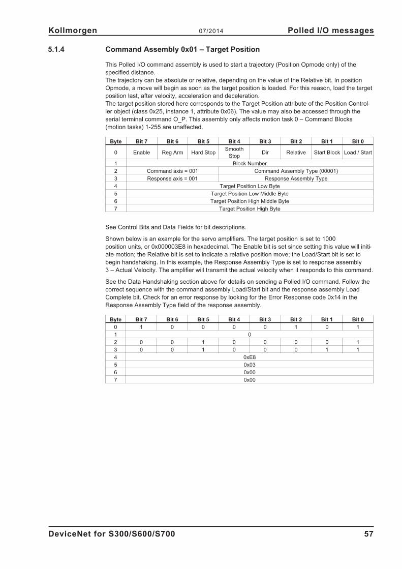
5.1.4 Command Assembly 0x01 – Target Position
This Polled I/O command assembly is used to start a trajectory (Position Opmode only) of the
specified distance.
The trajectory can be absolute or relative, depending on the value of the Relative bit. In position
Opmode, a move will begin as soon as the target position is loaded. For this reason, load the target
position last, after velocity, acceleration and deceleration.
The target position stored here corresponds to the Target Position attribute of the Position Control-
ler object (class 0x25, instance 1, attribute 0x06). The value may also be accessed through the
serial terminal command O_P. This assembly only affects motion task 0 – Command Blocks
(motion tasks) 1-255 are unaffected.
Byte Bit 7 Bit 6 Bit 5 Bit 4 Bit 3 Bit 2 Bit 1 Bit 0
0 Enable Reg Arm Hard StopSmooth
StopDir Relative Start Block Load / Start
1 Block Number
2 Command axis = 001 Command Assembly Type (00001)
3 Response axis = 001 Response Assembly Type
4 Target Position Low Byte
5 Target Position Low Middle Byte
6 Target Position High Middle Byte
7 Target Position High Byte
See Control Bits and Data Fields for bit descriptions.
Shown below is an example for the servo amplifiers. The target position is set to 1000
position units, or 0x000003E8 in hexadecimal. The Enable bit is set since setting this value will initi-
ate motion; the Relative bit is set to indicate a relative position move; the Load/Start bit is set to
begin handshaking. In this example, the Response Assembly Type is set to response assembly
3 – Actual Velocity. The amplifier will transmit the actual velocity when it responds to this command.
See the Data Handshaking section above for details on sending a Polled I/O command. Follow the
correct sequence with the command assembly Load/Start bit and the response assembly Load
Complete bit. Check for an error response by looking for the Error Response code 0x14 in the
Response Assembly Type field of the response assembly.
Byte Bit 7 Bit 6 Bit 5 Bit 4 Bit 3 Bit 2 Bit 1 Bit 0
0 1 0 0 0 0 1 0 1
1 0
2 0 0 1 0 0 0 0 1
3 0 0 1 0 0 0 1 1
4 0xE8
5 0x03
6 0x00
7 0x00
DeviceNet for S300/S600/S700 57
Kollmorgen 07/2014 Polled I/O messages

5.1.5 Command Assembly 0x02 – Target Velocity
This Polled I/O command assembly is used to change the target velocity in position or velocity
opmode. The Dir bit sets the desired direction in Velocity Mode and is ignored in all other modes.
In Velocity Mode, the move will begin as soon as the target velocity is loaded. In Position Mode,
movement will not start when the target velocity is loaded.
In position opmode, the velocity stored here corresponds to the Target Velocity attribute of the Posi-
tion Controller object (class 0x25, instance 1, attribute 0x07). In velocity opmode, the velocity stored
here corresponds to the Jog Velocity attribute of the Position Controller object (class 0x25, instance
1, attribute 0x16). This assembly only affects motion task 0 – Command Blocks (motion tasks)
1-255 are unaffected.
The units are determined by the amplifier setup (VUNIT, Position Controller attributes 40-41).
Byte Bit 7 Bit 6 Bit 5 Bit 4 Bit 3 Bit 2 Bit 1 Bit 0
0 Enable Reg Arm Hard StopSmooth
StopDir Relative Start Block Load / Start
1 Block Number
2 Command axis = 001 Command Assembly Type (00010)
3 Response axis = 001 Response Assembly Type
4 Target Velocity Low Byte
5 Target Velocity Low Middle Byte
6 Target Velocity High Middle Byte
7 Target Velocity High Byte
See Control Bits and Data Fields for bit descriptions.
Shown below is an example for the servo amplifiers. The target velocity is set to 20000 counts/sec,
or 0x00004e20 in hexadecimal. The Enable bit is set to enable the amplifier; the Direction bit is
cleared, so motion will be in the negative direction if the amplifier is in Velocity Mode; the Load/Start
bit is set to begin handshaking. In velocity mode, the amplifier will immediately accelerate or decel-
erate to -20000 counts/sec. In position mode, the target velocity will be loaded for the next trajec-
tory. In this example, the Response Assembly Type is set to response assembly 1 – Actual Posi-
tion. The amplifier will transmit the actual position when it responds to this command (refer to
Response Assembly 0x01 – Actual Position for more information).
See the Data Handshaking section above for details on sending a Polled I/O command. Follow the
correct sequence with the command assembly Load/Start bit and the response assembly Load
Complete bit. Check for an error response by looking for the Error Response code 0x14 in the
Response Assembly Type field of the response assembly.
Byte Bit 7 Bit 6 Bit 5 Bit 4 Bit 3 Bit 2 Bit 1 Bit 0
0 1 0 0 0 0 0 0 1
1 0
2 0 0 1 0 0 0 1 0
3 0 0 1 0 0 0 0 1
4 0x20
5 0x4E
6 0x00
7 0x00
58 DeviceNet for S300/S600/S700
Polled I/O messages 07/2014 Kollmorgen
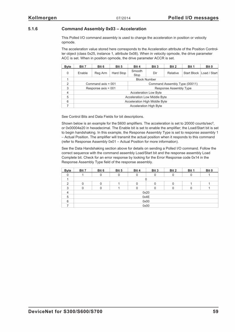
5.1.6 Command Assembly 0x03 – Acceleration
This Polled I/O command assembly is used to change the acceleration in position or velocity
opmode.
The acceleration value stored here corresponds to the Acceleration attribute of the Position Control-
ler object (class 0x25, instance 1, attribute 0x08). When in velocity opmode, the drive parameter
ACC is set. When in position opmode, the drive parameter ACCR is set.
Byte Bit 7 Bit 6 Bit 5 Bit 4 Bit 3 Bit 2 Bit 1 Bit 0
0 Enable Reg Arm Hard StopSmooth
StopDir Relative Start Block Load / Start
1 Block Number
2 Command axis = 001 Command Assembly Type (00011)
3 Response axis = 001 Response Assembly Type
4 Acceleration Low Byte
5 Acceleration Low Middle Byte
6 Acceleration High Middle Byte
7 Acceleration High Byte
See Control Bits and Data Fields for bit descriptions.
Shown below is an example for the S600 amplifiers. The acceleration is set to 20000 counts/sec²,
or 0x00004e20 in hexadecimal. The Enable bit is set to enable the amplifier; the Load/Start bit is set
to begin handshaking. In this example, the Response Assembly Type is set to response assembly 1
– Actual Position. The amplifier will transmit the actual position when it responds to this command
(refer to Response Assembly 0x01 – Actual Position for more information).
See the Data Handshaking section above for details on sending a Polled I/O command. Follow the
correct sequence with the command assembly Load/Start bit and the response assembly Load
Complete bit. Check for an error response by looking for the Error Response code 0x14 in the
Response Assembly Type field of the response assembly.
Byte Bit 7 Bit 6 Bit 5 Bit 4 Bit 3 Bit 2 Bit 1 Bit 0
0 1 0 0 0 0 0 0 1
1 0
2 0 0 1 0 0 0 1 1
3 0 0 1 0 0 0 0 1
4 0x20
5 0x4E
6 0x00
7 0x00
DeviceNet for S300/S600/S700 59
Kollmorgen 07/2014 Polled I/O messages
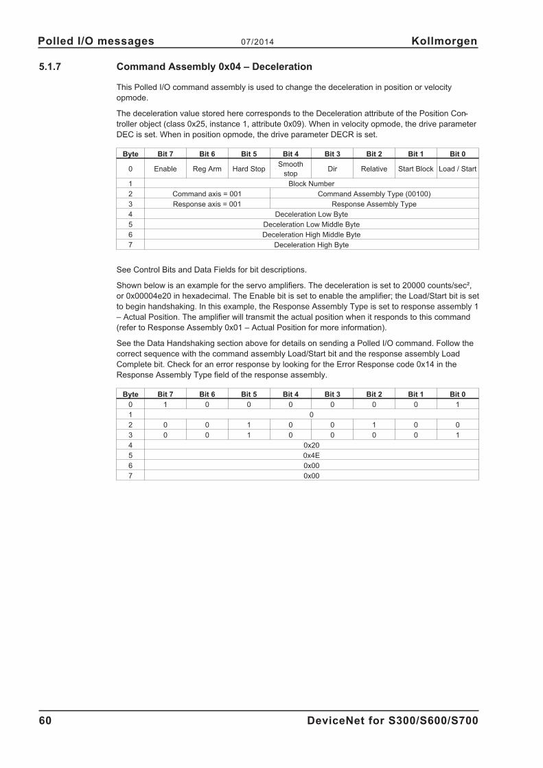
5.1.7 Command Assembly 0x04 – Deceleration
This Polled I/O command assembly is used to change the deceleration in position or velocity
opmode.
The deceleration value stored here corresponds to the Deceleration attribute of the Position Con-
troller object (class 0x25, instance 1, attribute 0x09). When in velocity opmode, the drive parameter
DEC is set. When in position opmode, the drive parameter DECR is set.
Byte Bit 7 Bit 6 Bit 5 Bit 4 Bit 3 Bit 2 Bit 1 Bit 0
0 Enable Reg Arm Hard StopSmooth
stopDir Relative Start Block Load / Start
1 Block Number
2 Command axis = 001 Command Assembly Type (00100)
3 Response axis = 001 Response Assembly Type
4 Deceleration Low Byte
5 Deceleration Low Middle Byte
6 Deceleration High Middle Byte
7 Deceleration High Byte
See Control Bits and Data Fields for bit descriptions.
Shown below is an example for the servo amplifiers. The deceleration is set to 20000 counts/sec²,
or 0x00004e20 in hexadecimal. The Enable bit is set to enable the amplifier; the Load/Start bit is set
to begin handshaking. In this example, the Response Assembly Type is set to response assembly 1
– Actual Position. The amplifier will transmit the actual position when it responds to this command
(refer to Response Assembly 0x01 – Actual Position for more information).
See the Data Handshaking section above for details on sending a Polled I/O command. Follow the
correct sequence with the command assembly Load/Start bit and the response assembly Load
Complete bit. Check for an error response by looking for the Error Response code 0x14 in the
Response Assembly Type field of the response assembly.
Byte Bit 7 Bit 6 Bit 5 Bit 4 Bit 3 Bit 2 Bit 1 Bit 0
0 1 0 0 0 0 0 0 1
1 0
2 0 0 1 0 0 1 0 0
3 0 0 1 0 0 0 0 1
4 0x20
5 0x4E
6 0x00
7 0x00
60 DeviceNet for S300/S600/S700
Polled I/O messages 07/2014 Kollmorgen
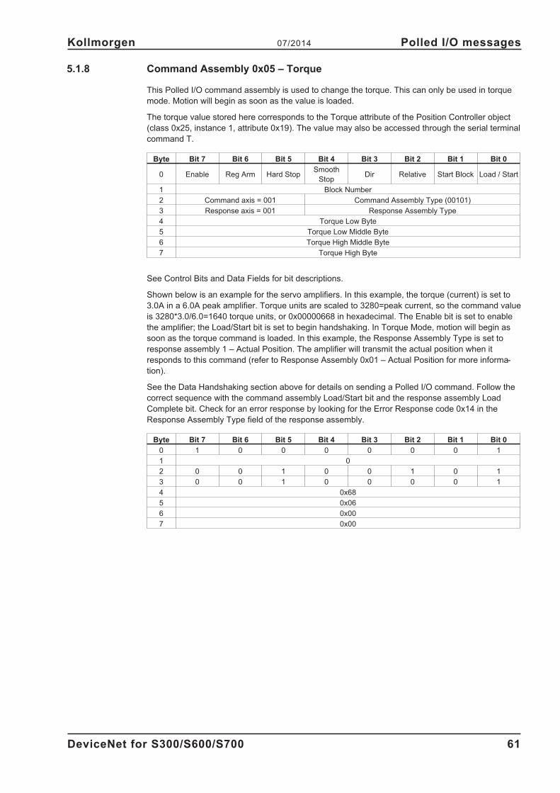
5.1.8 Command Assembly 0x05 – Torque
This Polled I/O command assembly is used to change the torque. This can only be used in torque
mode. Motion will begin as soon as the value is loaded.
The torque value stored here corresponds to the Torque attribute of the Position Controller object
(class 0x25, instance 1, attribute 0x19). The value may also be accessed through the serial terminal
command T.
Byte Bit 7 Bit 6 Bit 5 Bit 4 Bit 3 Bit 2 Bit 1 Bit 0
0 Enable Reg Arm Hard StopSmooth
StopDir Relative Start Block Load / Start
1 Block Number
2 Command axis = 001 Command Assembly Type (00101)
3 Response axis = 001 Response Assembly Type
4 Torque Low Byte
5 Torque Low Middle Byte
6 Torque High Middle Byte
7 Torque High Byte
See Control Bits and Data Fields for bit descriptions.
Shown below is an example for the servo amplifiers. In this example, the torque (current) is set to
3.0A in a 6.0A peak amplifier. Torque units are scaled to 3280=peak current, so the command value
is 3280*3.0/6.0=1640 torque units, or 0x00000668 in hexadecimal. The Enable bit is set to enable
the amplifier; the Load/Start bit is set to begin handshaking. In Torque Mode, motion will begin as
soon as the torque command is loaded. In this example, the Response Assembly Type is set to
response assembly 1 – Actual Position. The amplifier will transmit the actual position when it
responds to this command (refer to Response Assembly 0x01 – Actual Position for more informa-
tion).
See the Data Handshaking section above for details on sending a Polled I/O command. Follow the
correct sequence with the command assembly Load/Start bit and the response assembly Load
Complete bit. Check for an error response by looking for the Error Response code 0x14 in the
Response Assembly Type field of the response assembly.
Byte Bit 7 Bit 6 Bit 5 Bit 4 Bit 3 Bit 2 Bit 1 Bit 0
0 1 0 0 0 0 0 0 1
1 0
2 0 0 1 0 0 1 0 1
3 0 0 1 0 0 0 0 1
4 0x68
5 0x06
6 0x00
7 0x00
DeviceNet for S300/S600/S700 61
Kollmorgen 07/2014 Polled I/O messages

5.2 I/O Response Assemblies
Polled I/O Messaging is a method of transmitting a group of control bits and a data command and
receiving back a group of status bits and a data value response. This method of communication is
preferred, as explicit messaging can transmit only a single value at a time. Polled I/O Messaging is
a method of communicating to devices a group of specific commands. This method of communica-
tion is preferred, as it is faster than explicit messaging. Polled I/O and Explicit Messaging may be
used simultaneously for communications between the controller and the amplifier. In this section,
the format of each Response Assembly is defined and examples of each are provided.
In Polled I/O Messaging, the amplifier transmits a response assembly when it receives a command
assembly from the amplifier. The response assembly has status bits which are defined the same for
each type of response. In addition to status bits, a response assembly can transmit one data value
at a time (actual position, commanded position, actual velocity, actual torque or error values). The
response type is specified in the Response Assembly Type field of the command assembly. A com-
mand assembly may contain both a Command Assembly Type and a Response Assembly Type to
transmit a command and request a data value in the same assembly.
5.2.1 Status Bits and Data Fields
Byte Bit 7 Bit 6 Bit 5 Bit 4 Bit 3 Bit 2 Bit 1 Bit 0
0Enable
stateReg level Home level Current dir
General
faultin position
Block Exe-
cutingin Motion
1 Executing Block Number
2Load com-
pleteBlock fault
Following
error
Negative
SW limit
Positive
SW limit
Negative
HW limit
Positive
HW limit
Fault input
active
3 Response Axis = 001 Response Assembly Type
4 Data Low Byte
5 Data Low Middle Byte
6 Data High Middle Byte
7 Data High Byte
Enable State This bit reflects the enable state of the amplifier. See also Enable
(class 0x25 Position Controller, attribute 0x11).
Registration Level The actual level of the registration input. Digital input 2 must be configured for
registration.
Home Level This bit reflects the level of the Home Input of the amplifier.
Current Direction This bit reflects the actual direction of motion. When the drive is not in motion,
this bit shows the direction of the last commanded move. See also Direction
(class 0x25 Position Controller, attribute 0x17).
General Fault This bit indicates whether or not a fault has occurred. See also General Fault
(class 0x24 Position Controller Supervisor, attribute 0x05).
in position This bit indicates whether or not the motor is on the last targeted position
(1=On Target). See also Incremental Position Flag
(class 0x25 Position Controller, attribute 0x0C).
Block Executing When set, indicates amplifier is running a block command program. See also
Block Execute (class 0x26 Block Sequencer, attribute 0x02).
Executing Block Indicates the number (instance) of the currently executing block when the
Number Block Executing bit is high (1). See also Current Block
(class 0x26 Block Sequencer, attribute 0x03).
In Motion This bit indicates whether a trajectory is in progress (1) or has completed (0).
This bit is set immediately when motion begins and remains set for the entire
motion. See also Start Trajectory
(class 0x25 Position Controller, attribute 0x0B).
62 DeviceNet for S300/S600/S700
Polled I/O messages 07/2014 Kollmorgen
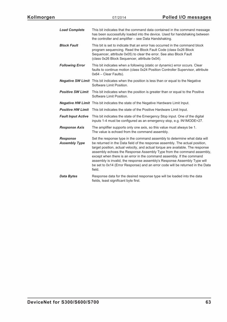
Load Complete This bit indicates that the command data contained in the command message
has been successfully loaded into the device. Used for handshaking between
the controller and amplifier – see Data Handshaking.
Block Fault This bit is set to indicate that an error has occurred in the command block
program sequencing. Read the Block Fault Code (class 0x26 Block
Sequencer, attribute 0x05) to clear the error. See also Block Fault
(class 0x26 Block Sequencer, attribute 0x04).
Following Error This bit indicates when a following (static or dynamic) error occurs. Clear
faults to continue motion (class 0x24 Position Controller Supervisor, attribute
0x64 – Clear Faults).
Negative SW Limit This bit indicates when the position is less than or equal to the Negative
Software Limit Position.
Positive SW Limit This bit indicates when the position is greater than or equal to the Positive
Software Limit Position.
Negative HW Limit This bit indicates the state of the Negative Hardware Limit Input.
Positive HW Limit This bit indicates the state of the Positive Hardware Limit Input.
Fault Input Active This bit indicates the state of the Emergency Stop input. One of the digital
inputs 1-4 must be configured as an emergency stop, e.g. IN1MODE=27.
Response Axis The amplifier supports only one axis, so this value must always be 1.
The value is echoed from the command assembly.
Response Set the response type in the command assembly to determine what data will
Assembly Type be returned in the Data field of the response assembly. The actual position,
target position, actual velocity, and actual torque are available. The response
assembly echoes the Response Assembly Type from the command assembly,
except when there is an error in the command assembly. If the command
assembly is invalid, the response assembly’s Response Assembly Type will
be set to 0x14 (Error Response) and an error code will be returned in the Data
field.
Data Bytes Response data for the desired response type will be loaded into the data
fields, least significant byte first.
DeviceNet for S300/S600/S700 63
Kollmorgen 07/2014 Polled I/O messages
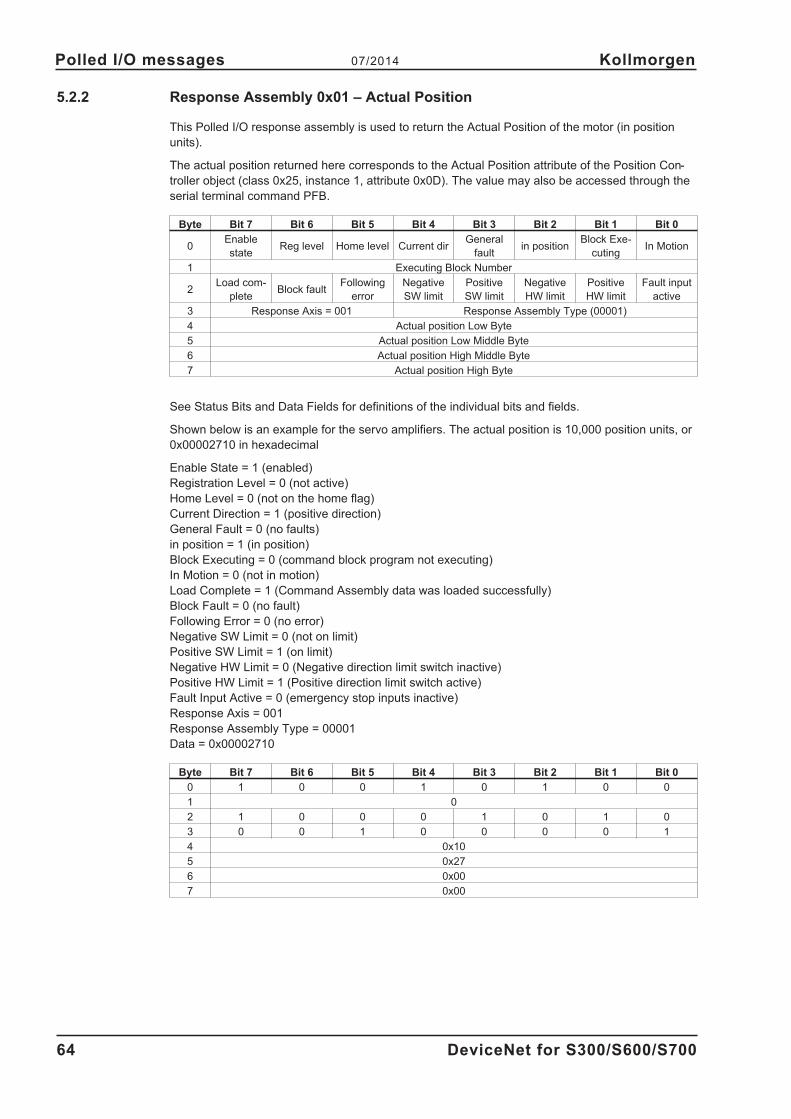
5.2.2 Response Assembly 0x01 – Actual Position
This Polled I/O response assembly is used to return the Actual Position of the motor (in position
units).
The actual position returned here corresponds to the Actual Position attribute of the Position Con-
troller object (class 0x25, instance 1, attribute 0x0D). The value may also be accessed through the
serial terminal command PFB.
Byte Bit 7 Bit 6 Bit 5 Bit 4 Bit 3 Bit 2 Bit 1 Bit 0
0Enable
stateReg level Home level Current dir
General
faultin position
Block Exe-
cutingIn Motion
1 Executing Block Number
2Load com-
pleteBlock fault
Following
error
Negative
SW limit
Positive
SW limit
Negative
HW limit
Positive
HW limit
Fault input
active
3 Response Axis = 001 Response Assembly Type (00001)
4 Actual position Low Byte
5 Actual position Low Middle Byte
6 Actual position High Middle Byte
7 Actual position High Byte
See Status Bits and Data Fields for definitions of the individual bits and fields.
Shown below is an example for the servo amplifiers. The actual position is 10,000 position units, or
0x00002710 in hexadecimal
Enable State = 1 (enabled)
Registration Level = 0 (not active)
Home Level = 0 (not on the home flag)
Current Direction = 1 (positive direction)
General Fault = 0 (no faults)
in position = 1 (in position)
Block Executing = 0 (command block program not executing)
In Motion = 0 (not in motion)
Load Complete = 1 (Command Assembly data was loaded successfully)
Block Fault = 0 (no fault)
Following Error = 0 (no error)
Negative SW Limit = 0 (not on limit)
Positive SW Limit = 1 (on limit)
Negative HW Limit = 0 (Negative direction limit switch inactive)
Positive HW Limit = 1 (Positive direction limit switch active)
Fault Input Active = 0 (emergency stop inputs inactive)
Response Axis = 001
Response Assembly Type = 00001
Data = 0x00002710
Byte Bit 7 Bit 6 Bit 5 Bit 4 Bit 3 Bit 2 Bit 1 Bit 0
0 1 0 0 1 0 1 0 0
1 0
2 1 0 0 0 1 0 1 0
3 0 0 1 0 0 0 0 1
4 0x10
5 0x27
6 0x00
7 0x00
64 DeviceNet for S300/S600/S700
Polled I/O messages 07/2014 Kollmorgen

5.2.3 Response Assembly 0x02 – Commanded Position
This Polled I/O response assembly is used to return the commanded position of the motor (in posi-
tion units).
The value may also be accessed through the serial terminal command PTARGET.
Byte Bit 7 Bit 6 Bit 5 Bit 4 Bit 3 Bit 2 Bit 1 Bit 0
0Enable
stateReg level Home level Current dir
General
faultin position
Block Exe-
cutingIn Motion
1 Executing Block Number
2Load com-
pleteBlock fault
Following
error
Negative
SW limit
Positive
SW limit
Negative
HW limit
Positive
HW limit
Fault input
active
3 Response Axis = 001 Response Assembly Type (00010)
4 Commanded position Low Byte
5 Commanded position Low Middle Byte
6 Commanded position High Middle Byte
7 Commanded position High Byte
See Status Bits and Data Fields for definitions of the individual bits and fields.
Shown below is an example for the servo amplifiers. The commanded position is 10,000 position
units, or 0x00002710 in hexadecimal.
Enable State = 1 (enabled)
Registration Level = 0 (not active)
Home Level = 0 (not on the home flag)
Current Direction = 1 (positive direction)
General Fault = 0 (no faults)
in position = 1 (in position)
Block Executing = 0 (command block program not executing)
In Motion = 0 (not in motion)
Load Complete = 1 (Command Assembly data was loaded successfully)
Block Fault = 0 (no fault)
Following Error = 0 (no error)
Negative SW Limit = 0 (not on limit)
Positive SW Limit = 1 (on limit)
Negative HW Limit = 0 (Negative direction limit switch inactive)
Positive HW Limit = 0 (Positive direction limit switch inactive)
Fault Input Active = 0 (emergency stop inputs inactive)
Response Axis = 001
Response Assembly Type = 00010
Data = 0x00002710
Byte Bit 7 Bit 6 Bit 5 Bit 4 Bit 3 Bit 2 Bit 1 Bit 0
0 1 0 0 1 0 1 0 0
1 0
2 1 0 0 0 1 0 0 0
3 0 0 1 0 0 0 1 0
4 0x10
5 0x27
6 0x00
7 0x00
DeviceNet for S300/S600/S700 65
Kollmorgen 07/2014 Polled I/O messages
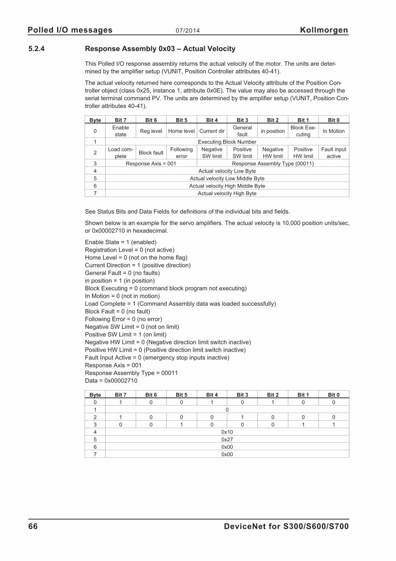
5.2.4 Response Assembly 0x03 – Actual Velocity
This Polled I/O response assembly returns the actual velocity of the motor. The units are deter-
mined by the amplifier setup (VUNIT, Position Controller attributes 40-41).
The actual velocity returned here corresponds to the Actual Velocity attribute of the Position Con-
troller object (class 0x25, instance 1, attribute 0x0E). The value may also be accessed through the
serial terminal command PV. The units are determined by the amplifier setup (VUNIT, Position Con-
troller attributes 40-41).
Byte Bit 7 Bit 6 Bit 5 Bit 4 Bit 3 Bit 2 Bit 1 Bit 0
0Enable
stateReg level Home level Current dir
General
faultin position
Block Exe-
cutingIn Motion
1 Executing Block Number
2Load com-
pleteBlock fault
Following
error
Negative
SW limit
Positive
SW limit
Negative
HW limit
Positive
HW limit
Fault input
active
3 Response Axis = 001 Response Assembly Type (00011)
4 Actual velocity Low Byte
5 Actual velocity Low Middle Byte
6 Actual velocity High Middle Byte
7 Actual velocity High Byte
See Status Bits and Data Fields for definitions of the individual bits and fields.
Shown below is an example for the servo amplifiers. The actual velocity is 10,000 position units/sec,
or 0x00002710 in hexadecimal.
Enable State = 1 (enabled)
Registration Level = 0 (not active)
Home Level = 0 (not on the home flag)
Current Direction = 1 (positive direction)
General Fault = 0 (no faults)
in position = 1 (in position)
Block Executing = 0 (command block program not executing)
In Motion = 0 (not in motion)
Load Complete = 1 (Command Assembly data was loaded successfully)
Block Fault = 0 (no fault)
Following Error = 0 (no error)
Negative SW Limit = 0 (not on limit)
Positive SW Limit = 1 (on limit)
Negative HW Limit = 0 (Negative direction limit switch inactive)
Positive HW Limit = 0 (Positive direction limit switch inactive)
Fault Input Active = 0 (emergency stop inputs inactive)
Response Axis = 001
Response Assembly Type = 00011
Data = 0x00002710
Byte Bit 7 Bit 6 Bit 5 Bit 4 Bit 3 Bit 2 Bit 1 Bit 0
0 1 0 0 1 0 1 0 0
1 0
2 1 0 0 0 1 0 0 0
3 0 0 1 0 0 0 1 1
4 0x10
5 0x27
6 0x00
7 0x00
66 DeviceNet for S300/S600/S700
Polled I/O messages 07/2014 Kollmorgen

5.2.5 Response Assembly 0x05 – Torque
This Polled I/O response assembly returns the actual torque (current) of the motor.
The actual torque returned here corresponds to the Torque attribute of the Position Controller object
(class 0x25, instance 1, attribute 0x19). The value may also be accessed through the serial terminal
command T.
Byte Bit 7 Bit 6 Bit 5 Bit 4 Bit 3 Bit 2 Bit 1 Bit 0
0Enable
stateReg level Home level Current dir
General
faultin position
Block Exe-
cutingIn Motion
1 Executing Block Number
2Load com-
pleteBlock fault
Following
error
Negative
SW limit
Positive
SW limit
Negative
HW limit
Positive
HW limit
Fault input
active
3 Response Axis = 001 Response Assembly Type (00101)
4 Torque Low Byte
5 Torque Low Middle Byte
6 Torque High Middle Byte
7 Torque High Byte
See Status Bits and Data Fields for definitions of the individual bits and fields.
Shown below is an example for the servo amplifiers. The actual torque (current) is 3.0A in a 6.0A
peak amplifier. Torque units are scaled to 3280=peak current, so the actual torque value is
3280*3.0/6.0=1640 torque units, or 0x00000668 in hexadecimal.
Enable State = 1 (enabled)
Registration Level = 0 (not active)
Home Level = 0 (not on the home flag)
Current Direction = 1 (positive direction)
General Fault = 0 (no faults)
in position = 1 (in position)
Block Executing = 0 (command block program not executing)
In Motion = 1 (motion in progress)
Load Complete = 0 (no data loaded from the Command Assembly)
Block Fault = 0 (no fault)
Following Error = 0 (no error)
Negative SW Limit = 0 (not on limit)
Positive SW Limit = 0 (not on limit)
Negative HW Limit = 0 (Negative direction limit switch inactive)
Positive HW Limit = 0 (Positive direction limit switch inactive)
Fault Input Active = 0 (emergency stop inputs inactive)
Response Axis = 001
Response Assembly Type = 00101
Data = 0x00000668
Byte Bit 7 Bit 6 Bit 5 Bit 4 Bit 3 Bit 2 Bit 1 Bit 0
0 1 0 0 1 0 1 0 1
1 0
2 0 0 0 0 0 0 0 0
3 0 0 1 0 0 1 0 1
4 0x68
5 0x06
6 0x00
7 0x00
DeviceNet for S300/S600/S700 67
Kollmorgen 07/2014 Polled I/O messages
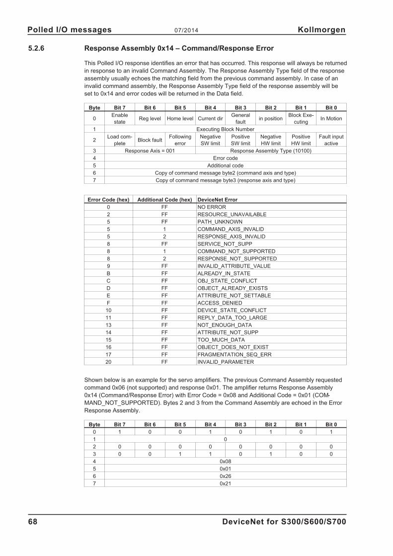
5.2.6 Response Assembly 0x14 – Command/Response Error
This Polled I/O response identifies an error that has occurred. This response will always be returned
in response to an invalid Command Assembly. The Response Assembly Type field of the response
assembly usually echoes the matching field from the previous command assembly. In case of an
invalid command assembly, the Response Assembly Type field of the response assembly will be
set to 0x14 and error codes will be returned in the Data field.
Byte Bit 7 Bit 6 Bit 5 Bit 4 Bit 3 Bit 2 Bit 1 Bit 0
0Enable
stateReg level Home level Current dir
General
faultin position
Block Exe-
cutingIn Motion
1 Executing Block Number
2Load com-
pleteBlock fault
Following
error
Negative
SW limit
Positive
SW limit
Negative
HW limit
Positive
HW limit
Fault input
active
3 Response Axis = 001 Response Assembly Type (10100)
4 Error code
5 Additional code
6 Copy of command message byte2 (command axis and type)
7 Copy of command message byte3 (response axis and type)
Error Code (hex) Additional Code (hex) DeviceNet Error
0 FF NO ERROR
2 FF RESOURCE_UNAVAILABLE
5 FF PATH_UNKNOWN
5 1 COMMAND_AXIS_INVALID
5 2 RESPONSE_AXIS_INVALID
8 FF SERVICE_NOT_SUPP
8 1 COMMAND_NOT_SUPPORTED
8 2 RESPONSE_NOT_SUPPORTED
9 FF INVALID_ATTRIBUTE_VALUE
B FF ALREADY_IN_STATE
C FF OBJ_STATE_CONFLICT
D FF OBJECT_ALREADY_EXISTS
E FF ATTRIBUTE_NOT_SETTABLE
F FF ACCESS_DENIED
10 FF DEVICE_STATE_CONFLICT
11 FF REPLY_DATA_TOO_LARGE
13 FF NOT_ENOUGH_DATA
14 FF ATTRIBUTE_NOT_SUPP
15 FF TOO_MUCH_DATA
16 FF OBJECT_DOES_NOT_EXIST
17 FF FRAGMENTATION_SEQ_ERR
20 FF INVALID_PARAMETER
Shown below is an example for the servo amplifiers. The previous Command Assembly requested
command 0x06 (not supported) and response 0x01. The amplifier returns Response Assembly
0x14 (Command/Response Error) with Error Code = 0x08 and Additional Code = 0x01 (COM-
MAND_NOT_SUPPORTED). Bytes 2 and 3 from the Command Assembly are echoed in the Error
Response Assembly.
Byte Bit 7 Bit 6 Bit 5 Bit 4 Bit 3 Bit 2 Bit 1 Bit 0
0 1 0 0 1 0 1 0 1
1 0
2 0 0 0 0 0 0 0 0
3 0 0 1 1 0 1 0 0
4 0x08
5 0x01
6 0x26
7 0x21
68 DeviceNet for S300/S600/S700
Polled I/O messages 07/2014 Kollmorgen

6 Appendix
6.1 DeviceNet PLC Examples
6.1.1 Overview
DeviceNet provides three methods for controlling motion – Explicit Messages, Assembly Messages,
and Command Block Sequences. Each method provides advantages over the others in certain situ-
ations. Typically, Explicit Messages are used to configure the amplifier, Assemblies are used to
control movement, and Command Blocks are used when stored motion sequences may be exe-
cuted without much PLC involvement.
Most PLC’s will support both Explicit and Polled I/O (Assembly) messaging simultaneously. The
objects described in Section 4 are all accessed though Explicit Messaging. Section 5 describes the
use of Polled I/O command and response assemblies. Command Block Sequences can be setup
through Explicit Messsages and then controlled with either Explicit Messages or Polled I/O.
Explicit Messages allow you to access a single parameter value at a time. The desired parameter is
selected by specifying the class number, instance number and attribute number in an explicit mes-
sage. Assemblies combine many control and status bits into 8-byte command and response mes-
sages. They are less versatile than explicit messages (only certain parameters are accessible), but
several control values may be changes within one message. For this reason, Explicit Messages are
better for configuration and Assemblies are better for motion control.
Most drive configuration is done within the Position Controller Object, which encompasses most
parameters necessary for motion control. Modify parameters in this object to set the operational
mode (torque, velocity, position) and configure motion in the servo amplifier. View parameters in
this object to read the drive parameters and status words. Additional drive configuration may be
done through another supported object, the Parameter Object. This is a vendor-defined object
which exposes vendor configuration parameters. Any drive parameter with a DPR number less than
256 (see the ascii.chm reference) may be accessed through the Parameter Object.
Polled I/O Assemblies are used for most motion control. Polled I/O consists of a Command Assem-
bly from the PLC to the servo amplifier and a Response Assembly from the servo amplifier to the
PLC. Control bits in a command message are used to enable the amplifier, perform a controlled
stop of the motor, initiate motion, or initiate stored motion block programs. Command messages
can also set the target position, target velocity, acceleration, deceleration or torque parameters.
Status bits in a response message display error states and the general state of the amplifier.
Response messages can also display the actual position, commanded position, actual velocity or
torque.
Motion sequences or tasks may be pre-programmed into the amplifier through the Command Block
Object class. These blocks correspond to the servo amplifier motion tasking feature. Positioning
moves, time delays, and parameter modification blocks may be linked together to create a motion
block program that is stored in the amplifier. Once the stored block program has been configured, it
may be executed through either the Block Sequencer Object or with the Polled I/O Command Mes-
sage block number field and start block bit.
DeviceNet for S300/S600/S700 69
Kollmorgen 07/2014 Appendix

6.1.2 Amplifier Setup for the Examples
To test our examples, start by configuring your amplifier to match our example setup.
In the Basic Setup screen, set:
Acceleration units = ms->VLIM
Velocity units = rpm
Position units = counts
In the Position->Position Data screen, set:
Resolution = 1000 counts / revolution
In the Digital IO screen, set:
DIGITAL-OUT 1 = 23: Reserved
(Digital output function 23 puts the digital output under field bus control).
Save parameters and restart the amplifier.
The examples in this section assume these units have been set. The amplifier must also be prop-
erly tuned and configured before continuing.
When the amplifier is properly configured, execute the following command sequence from the serial
terminal to test. The motor shaft should rotate 1 revolution in 1 second when the MOVE 0 command
is entered.
Command Description
OPMODE 8 Put the amplifier in position mode.
EN Enable
MH Move Home
O_C 8193 Incremental move using user units
O_P 1000 Move 1000 counts (1 revolution)
O_V 60 Velocity=60 RPM
O_ACC1 10 Acceleration = 10ms to target velocity
O_DEC1 10 Deceleration = 10ms to target velocity
MOVE 0 Execution motion task 0
6.1.3 Polled I/O Assemblies
Assemblies are described thoroughly in the following sections: Typical Use of Explicit and Assembly
Messages, Command Assemblies, and Response Assemblies. See these sections for information
on the structure and use of command and response assemblies.
For Polled I/O Assembly messaging, the PLC initiates communication with a Command Assembly
and the amplifier responds with a Response Assembly. The PLC sends these messages at a regu-
lar ‘poll rate’. A handshaking protocol is used to ensure that data is transmitted correctly – see the
Data Handshaking section for a description of this protocol.
70 DeviceNet for S300/S600/S700
Appendix 07/2014 Kollmorgen
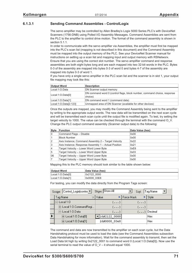
6.1.3.1 Sending Command Assemblies - ControlLogix
The servo amplifier may be controlled by Allen Bradley’s Logix 5000 Series PLC’s with DeviceNet
Scanners (1756-DNB) using Polled I/O Assembly Messages. Command Assemblies are sent from
the PLC to the amplifier to control drive motion. The format of the command assembly is shown in
section 5.1.1.
In order to communicate with the servo amplifier via Assemblies, the amplifier must first be mapped
into the PLC’s scan list (mapping is not described in this document) and the Command Assembly
must be mapped into the output memory of the PLC. See your DeviceNet Scanner manual for
instructions on setting up a scan list and mapping input and output memory with RSNetworx.
Ensure that you are using the correct slot number. The servo amplifier command and response
assemblies are both eight bytes long and are each mapped into two 32-bit words in the PLC. Bytes
0-3 of the assembly are mapped into bytes 0-3 of word 0 and bytes 4-7 of the assembly are
mapped into bytes 0-3 of word 1.
If you have only a single servo amplifier in the PLC scan list and the scanner is in slot 1, your output
file mapping may look like this:
Output Word Description
Local:1:O.Data DN Scanner output memory
Local:1:O.Data[0]DN command word 0 (control flags, block number, command choice, response
choice)
Local:1:O.Data[1] DN command word 1 (command data)
Local:1:O.Data[2-123] Unmapped area of DN Scanner (available for other devices)
Once the outputs are mapped, you may modify the Command Assembly being sent to the amplifier
by writing to the appropriate output words. The new data will be transmitted on the next scan cycle
and will be transmitted each scan cycle until the output file is modified again. To test, try setting the
target velocity to 1000. The value can be checked through the terminal with the command O_V.
Change the PLC output command assembly (Scanner output data) to the following:
Byte Function Data Value (hex)
0 Command Flags – Disable 0x00
1 Block Number 0x00
2 Axis Instance; Command Assembly 2 – Target Velocity 0x22
3 Axis Instance; Response Assembly 1 – Actual Position 0x21
4 Target Velocity – Lower Word Lower Byte 0xE8
5 Target Velocity – Lower Word Upper Byte 0x03
06 Target Velocity – Upper Word Lower Byte 0x00
7 Target Velocity – Upper Word Upper Byte 0x00
Mapping this to the PLC memory should look similar to the table shown below:
Output Word Data Value (hex)
Local:1:O.Data[0] 0x2122_0000
Local:1:O.Data[1] 0x0000_03E8
For testing, you can modify the data directly from the Program Tags screen:
The command and data are now transmitted to the amplifier on each scan cycle, but the Data
Handshaking protocol must be used to load the data (see the Command Assemblies subsection
Data Handshaking for more information). Wait for the command assembly to transmit, then set the
Load Data bit high by writing 0x2122_0001 to command word 0 (Local:1:O.Data[0]). Now use the
serial terminal to read the value of O_V – it should equal 1000.
DeviceNet for S300/S600/S700 71
Kollmorgen 07/2014 Appendix

6.1.3.2 Reading Response Assemblies - ControlLogix
A Response Assembly is a Polled I/O message sent to the PLC from the amplifier in reponse to a
command assembly. The amplifier will send a response assembly each time it receives a command
assembly from the PLC. If the command assembly is valid and the Response Assembly Type field
contains a valid response type, the amplifier will also load the requested data into the response
assembly. The data will be refreshed on each Polled I/O cycle until the command assembly
changes.
The format of this assembly is shown in section 5.2.1.
The response assembly must be mapped into the input memory of the PLC. See your DeviceNet
Scanner manual for instructions on setting up a scan list and mapping the memory with RSNetworx.
Ensure that you are using the correct slot number. See the previous section for a mapping diagram.
If you have only a single servo amplifier in the PLC scan list and the scanner is in slot 1, your input
file mapping may look like this:
Input Word Description
Local:1:I.Data DN Scanner input memory
Local:1:I.Data[0] DN response word 0 (status flags, block number, response choice)
Local:1:I.Data[1] DN response word 1 (response data)
Local:1:I.Data[2-123] Unmapped area of DN scanner (available for other devices)
Once the inputs are mapped, you may read the latest Response Assembly received by the PLC by
reading from the appropriate input file. The input files will be updated by the PLC on each scan
cycle with data transmitted from the amplifier.
To test, use the output command assembly from the previous section. The example command
assembly requests the actual position (Response Assembly Type = 1). After writing this command
assembly to the output file, wait for the scan cycle to complete, then read the input file to get the lat-
est response assembly. The response assembly should look something like the following, with the
motor’s actual position in bytes 4-7:
Byte Function Data value (Hex)
0 Response Flags A – Disabled, In Position 0x04
1 Block Executing - none 0x00
2 Response flags B - Load complete, no errors 0x80
3 Axis instance 1; response assembly 1 - actual position 0x21
4 Actual position - lower word lower byte 0x00
5 Actual position - lower word upper byte 0x00
6 Actual position - upper word lower byte 0x00
7 Actual position - upper word upper byte 0x00
Mapping this to the PLC memory should look similar to the table shown below:
Input Word Data Value (hex)
Local:1:I.Data[0] 0x2180_0004
Local:1:I.Data[1] 0x0000_0000
You can view the data easily in the Program Tags screen.
The value in Local:1:I.Data[1] should change as you rotate the motor shaft by hand.
72 DeviceNet for S300/S600/S700
Appendix 07/2014 Kollmorgen
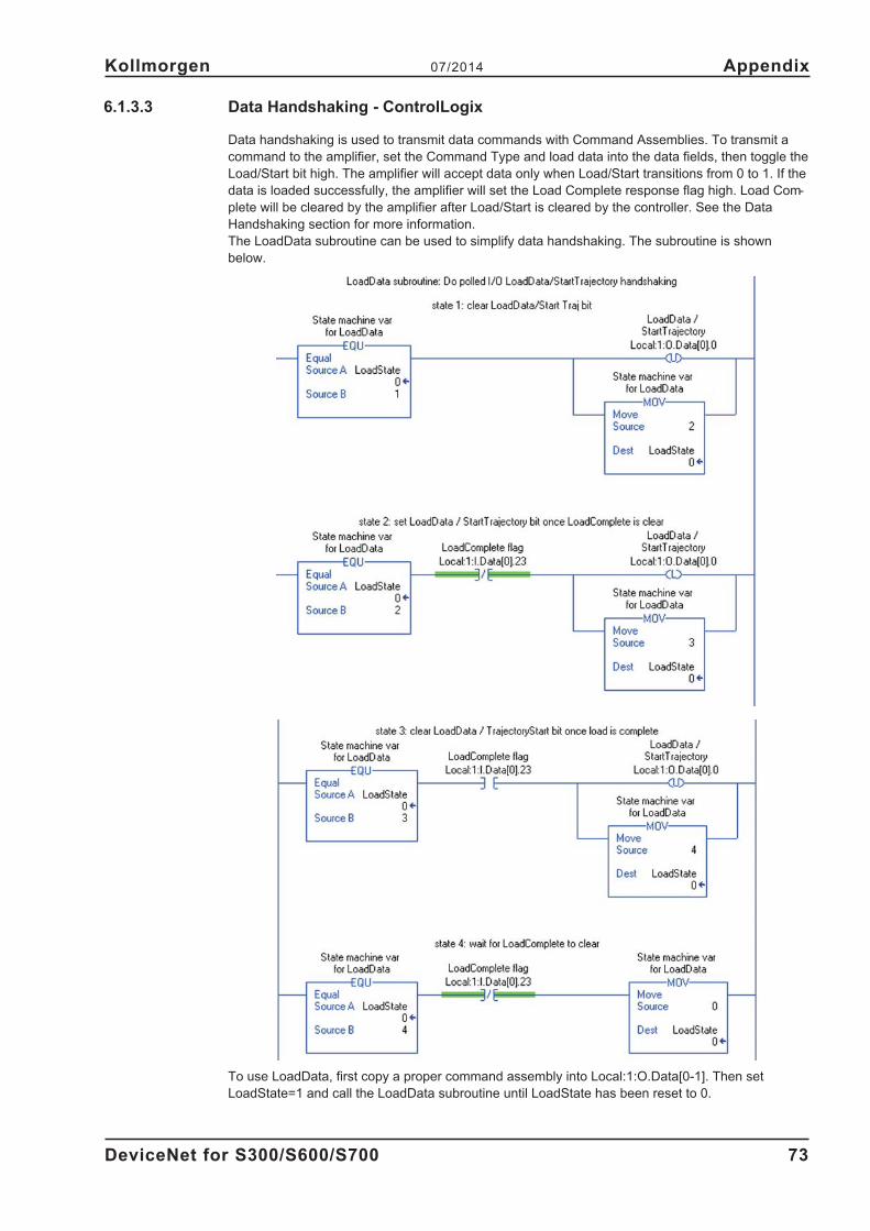
6.1.3.3 Data Handshaking - ControlLogix
Data handshaking is used to transmit data commands with Command Assemblies. To transmit a
command to the amplifier, set the Command Type and load data into the data fields, then toggle the
Load/Start bit high. The amplifier will accept data only when Load/Start transitions from 0 to 1. If the
data is loaded successfully, the amplifier will set the Load Complete response flag high. Load Com-
plete will be cleared by the amplifier after Load/Start is cleared by the controller. See the Data
Handshaking section for more information.
The LoadData subroutine can be used to simplify data handshaking. The subroutine is shown
below.
To use LoadData, first copy a proper command assembly into Local:1:O.Data[0-1]. Then set
LoadState=1 and call the LoadData subroutine until LoadState has been reset to 0.
DeviceNet for S300/S600/S700 73
Kollmorgen 07/2014 Appendix

6.1.3.4 Sending Command Assemblies - SLC500
The servo amplifier may be controlled by Allen Bradley’s SLC-5/0X Series PLC’s DeviceNet Scan-
ners (1747-SDN/B) using Assembly Messages. Command Assemblies are sent from the PLC to the
amplifier to control motion. The format of the command assembly is shown in section 5.1.1.
In order to communicate with the servo amplifiers via Assemblies, the drive must first be mapped
into the PLC’s scan list (mapping is not described in this document) and the Command Assembly
must be mapped into the output memory of the PLC. See your DeviceNet Scanner manual for
instructions on setting up a scan list and mapping input and output memory with RSNetworx.
Ensure that you are using the correct slot number. The amplifier command and response assem-
blies are both eight bytes long and are each mapped into four 32-bit words in the PLC:
If you have only a single servo amplifier in the PLC scan list and the scanner is in slot 1, your output
file mapping may look like this:
Output Word Description
O:1.0 DN Scanner Control Word
O:1.0/0 Enable DN Scanner Outputs
O:1.1 DN command word 0 (control flags, block number)
O:1.2 DN command word 1 (command, response)
O:1.3 DN command word 2 (data LSW)
O:1.4 DN command word 3 (data MSW)
O:1.5-31 Unmapped area of DN scanner (available for other devices)
Once the outputs are mapped, you may modify the Command Assembly being sent to the amplifier
by writing to the appropriate output file. The new data will be transmitted on the next scan cycle and
will be transmitted each scan cycle until the output file is modified again.
74 DeviceNet for S300/S600/S700
Appendix 07/2014 Kollmorgen
Byte 0
Byte 1
Byte 2
Byte 3
Byte 4
Byte 5
Byte 6
Byte 7
Byte 0Byte 1
Byte 2Byte 3
Byte 4Byte 5
Byte 6Byte 7
Word 0
Word 1
Word 2
Word 3

To test, try setting the target velocity to 1000. The value can be checked through the terminal with
the command O_V. Change the PLC output command assembly (Scanner output data) to the fol-
lowing:
Byte Function Data value (hex)
0 Command Flags – Disable 0x00
1 Block Number 0x00
2 Axis instance, command assembly 2 - target velocity 0x22
3 Axis instance, response assembly 1 - actual position 0x21
4 Target velocity - lower word lower byte 0xE8
5 Target velocity - lower word upper byte 0x03
6 Target velocity - lower word lower byte 0x00
7 Target velocity - upper word upper byte 0x00
Mapping this to the PLC memory should look similar to the table shown below:
Output Word Data Value (hex)
O:1.1 0000
O:1.2 2122
O:1.3 03E8
O:1.4 0000
For testing, you can modify the data directly from the Program Tags screen:
DeviceNet for S300/S600/S700 75
Kollmorgen 07/2014 Appendix

Alternately, a ladder program can load the desired values into the output words (note that the data
is displayed here in decimal):
The command and data are now transmitted to the amplifier on each scan cycle, but the Data
Handshaking protocol must be used to load the data. Wait for the command assembly to transmit,
then set the Load Data bit high by writing 0x0001 to command word 0 (Output Word O:1.1). Now
use the serial terminal to read the value of O_V – it should equal 1000.
76 DeviceNet for S300/S600/S700
Appendix 07/2014 Kollmorgen

6.1.3.5 Reading Response Assemblies - SLC500
A Response Assembly is a Polled I/O message sent to the PLC from the amplifier in reponse to a
command assembly. The amplifier will send a response assembly each time it receives a command
assembly from the PLC. If the command assembly is valid and the Response Assembly Type field
contains a valid response type, the amplifier will also load the requested data into the response
assembly. The data will be refreshed on each Polled I/O cycle until the command assembly
changes.
The format of this assembly is shown in section 5.2.1.
The response assembly must be mapped into the input memory of the PLC. See your DeviceNet
Scanner manual for instructions on setting up a scan list and mapping the memory with RSNetworx.
Ensure that you are using the correct slot number. See the previous section for a mapping diagram.
If you have only a single servo amplifier in the PLC scan list and the scanner is in slot 1, your input
file mapping may look like this:
Input Word Description
I:1.0 DN Scanner Status Word
I:1.1 DN response word 0 (control flags, block number)
I:1.2 DN response word 1 (command, response)
I:1.3 DN response word 2 (data LSW)
I:1.4 DN response word 3 (data MSW)
I:1.5-31 Unmapped area of DN scanner (available for other devices)
Once the inputs are mapped, you may read the latest Response Assembly received by the PLC by
reading from the appropriate input file. The input files will be updated by the PLC on each scan
cycle with data transmitted from the amplifier.
To test, use the output command assembly from the previous section. The example command
assembly requests the actual position (Response Assembly Type = 1). After writing this command
assembly to the output file, wait for the scan cycle to complete, then read the input file to get the lat-
est response assembly. The response assembly should look something like the following, with the
motor’s actual position in bytes 4-7:
Byte Function Data value (hex)
0 Response Flags A – Disabled, In Position 0x04
1 Block Executing - none 0x00
2 Response flags B - load complete, no errors 0x80
3 Axis instance 1; Response assembly 1 - actual position 0x21
4 Actual position - lower word lower byte 0x00
5 Actual position - lower word upper byte 0x00
6 Actual position - upper word lower byte 0x00
7 Actual position - upper word upper byte 0x00
DeviceNet for S300/S600/S700 77
Kollmorgen 07/2014 Appendix

Mapping this to the PLC memory should look similar to the table shown below:
Input Word Data Value (hex)
I:1.1 0000
I:1.2 2180
I:1.3 0000
I:1.4 0000
You can view the data easily in the Program Tags screen.
78 DeviceNet for S300/S600/S700
Appendix 07/2014 Kollmorgen

6.1.3.6 Data Handshaking - SLC500
Data handshaking is used to transmit data commands with Command Assemblies. To transmit a
command to the amplifier, set the Command Type and load data into the data fields, then toggle the
Load/Start bit high. The amplifier will accept data only when Load/Start transitions from 0 to 1. If the
data is loaded successfully, the amplifier will set the Load Complete response flag high. Load Com-
plete will be cleared by the amplifier after Load/Start is cleared by the controller. See the Data
Handshaking section for more information.
The LoadData subroutine can be used to simplify data handshaking. The subroutine is shown below
To use LoadData, first copy a proper command assembly into I:1.1-4. Then set N47:0=1 and call
the LoadData subroutine until N47:0 has been reset to 0.
DeviceNet for S300/S600/S700 79
Kollmorgen 07/2014 Appendix
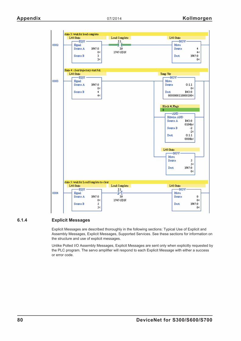
6.1.4 Explicit Messages
Explicit Messages are described thoroughly in the following sections: Typical Use of Explicit and
Assembly Messages, Explicit Messages, Supported Services. See these sections for information on
the structure and use of explicit messages.
Unlike Polled I/O Assembly Messages, Explicit Messages are sent only when explicitly requested by
the PLC program. The servo amplifier will respond to each Explicit Message with either a success
or error code.
80 DeviceNet for S300/S600/S700
Appendix 07/2014 Kollmorgen
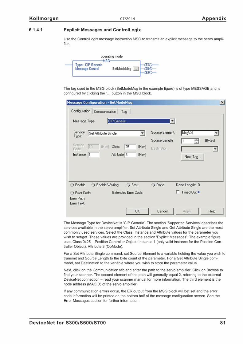
6.1.4.1 Explicit Messages and ControlLogix
Use the ControlLogix message instruction MSG to transmit an explicit message to the servo ampli-
fier.
The tag used in the MSG block (SetModeMsg in the example figure) is of type MESSAGE and is
configured by clicking the ‘...’ button in the MSG block.
The Message Type for DeviceNet is ‘CIP Generic’. The section ‘Supported Services’ describes the
services available in the servo amplifier. Set Attribute Single and Get Attribute Single are the most
commonly used services. Select the Class, Instance and Attribute values for the parameter you
wish to set/get. These values are provided in the section ‘Explicit Messages’. The example figure
uses Class 0x25 – Position Controller Object, Instance 1 (only valid instance for the Position Con-
troller Object), Attribute 3 (OpMode).
For a Set Attribute Single command, set Source Element to a variable holding the value you wish to
transmit and Source Length to the byte count of the parameter. For a Get Attribute Single com-
mand, set Destination to the variable where you wish to store the parameter value.
Next, click on the Communication tab and enter the path to the servo amplifier. Click on Browse to
find your scanner. The second element of the path will generally equal 2, referring to the external
DeviceNet connection – read your scanner manual for more information. The third element is the
node address (MACID) of the servo amplifier.
If any communication errors occur, the ER output from the MSG block will bet set and the error
code information will be printed on the bottom half of the message configuration screen. See the
Error Messages section for further information.
DeviceNet for S300/S600/S700 81
Kollmorgen 07/2014 Appendix

6.1.4.2 Explicit Messages and SLC500
With a SLC500 processor, explicit messages are transmitted by writing to the M0 file and received
by reading from the M1 file. If the scanner is in slot 1, the explicit message request structure is a
32-byte area in M0:1.224-255 and the explicit message response structure is a 32-byte area in
M1:1.224-255. See your scanner manual for more information.
For this example, create a 32-byte output buffer and a 32-byte input buffer. Explicit Message
requests are built in the output buffer, then copied to the M0 file. The response message in M1 is
copied into the input buffer for further processing.
6.1.4.2.1 SLC500 Explicit Message Request Structure
Byte 1 Byte 0 PLC output buffer M0 Memory
TX_ID = 1 TX_CMD = 1,4 WORD 0 WORD 224
PORT= 0 MSG_SIZE (in bytes) WORD 1 WORD 225
SERVICE MAC ID (node address) WORD 2 WORD 226
CLASS WORD 3 WORD 227
INSTANCE WORD 4 WORD 228
ATTRIBUTE WORD 5 WORD 229
LOWER DATA WORD WORD 6 WORD 230
UPPER DATA WORD WORD 7 WORD 231
TX_ID The Transaction ID is an index into the scanner’s explicit message queue.
The scanner can queue messages to multiple devices and send them when it is able.
For our purposes in this example, we always use Transaction ID 1.
TX_CMD The Transaction Command to perform on the transaction block specified by TX_ID.
01 Send Explicit Message.
04 Clear response buffer
(necessary before sending a new message with the same TX_ID).
PORT 0 – Channel A. (typical choice)
1 – Channel B.
MSG_SIZE Size in bytes of all data after the MAC ID (words 3-7). For a message which sets a
boolean (1 byte) parameter, the message size will be 7; 2 bytes each for the class,
instance and attribute plus 1 byte for the data value.
SERVICE The DeviceNet service to perform. See the section Supported Services for more
information.
0x0E – Get.
0x10 – Set.
MAC ID The DeviceNet ID of the servo amplifier as specified by the two MACID switches.
If the switches are set to 25 (the switches read as decimal), then this value is set to 19h.
CLASS DeviceNet class to access. Examples:
Parameter Object – 0x0F
Position Controller Supervisor – 0x24
Position Controller Object – 0x25
INSTANCE DeviceNet instance number. Examples:
Always 0x01 for Position Controller Object.
Parameter number (DPR number in ascii reference) for Parameter Object.
Port number for Analog and Digital I/O.
ATTRIBUTE The attribute number of the attribute being accessed (set or get).
LOWER/UPPER DATA WORD The data value for a Set service.
82 DeviceNet for S300/S600/S700
Appendix 07/2014 Kollmorgen
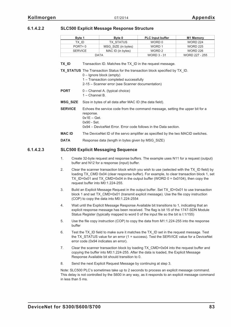
6.1.4.2.2 SLC500 Explicit Message Response Structure
Byte 1 Byte 0 PLC Input buffer M1 Memory
TX_ID TX_STATUS WORD 0 WORD 224
PORT= 0 MSG_SIZE (in bytes) WORD 1 WORD 225
SERVICE MAC ID (in bytes) WORD 2 WORD 226
DATA WORD 3 - 31 WORD 227 - 255
TX_ID Transaction ID. Matches the TX_ID in the request message.
TX_STATUS The Transaction Status for the transaction block specified by TX_ID.
0 – Ignore block (empty)
1 – Transaction completed successfully
2-15 – Scanner error (see Scanner documentation)
PORT 0 – Channel A. (typical choice)
1 – Channel B.
MSG_SIZE Size in bytes of all data after MAC ID (the data field).
SERVICE Echoes the service code from the command message, setting the upper bit for a
response.
0x1E – Get.
0x90 - Set.
0x94 – DeviceNet Error. Error code follows in the Data section.
MAC ID The DeviceNet ID of the servo amplifier as specified by the two MACID switches.
DATA Response data (length in bytes given by MSG_SIZE)
6.1.4.2.3 SLC500 Explicit Messaging Sequence
1. Create 32-byte request and response buffers. The example uses N11 for a request (output)
buffer and N12 for a response (input) buffer.
2. Clear the scanner transaction block which you wish to use (selected with the TX_ID field) by
loading TX_CMD 0x04 (clear response buffer). For example, to clear transaction block 1, set
TX_ID=0x01 and TX_CMD=0x04 in the output buffer (WORD 0 = 0x0104), then copy the
request buffer into M0:1.224-255.
3. Build an Explicit Message Request in the output buffer. Set TX_ID=0x01 to use transaction
block 1 and set TX_CMD=0x01 (transmit explicit message). Use the file copy instruction
(COP) to copy the data into M0:1.224-2554
4. Wait until the Explicit Message Response Available bit transitions to 1, indicating that an
explicit response message has been received. The flag is bit 15 of the 1747-SDN Module
Status Register (typically mapped to word 0 of the input file so the bit is I:1/155)
5. Use the file copy instruction (COP) to copy the data from M1:1.224-255 into the response
buffer
6. Test the TX_ID field to make sure it matches the TX_ID set in the request message. Test
the TX_STATUS value for an error (1 = success). Test the SERVICE value for a DeviceNet
error code (0x94 indicates an error).
7. Clear the scanner transaction block by loading TX_CMD=0x04 into the request buffer and
copying the buffer into M0:1.224-255. After the data is loaded, the Explicit Message
Response Available bit should transition to 0.
8. Send the next Explicit Request Message by continuing at step 3.
Note: SLC500 PLC’s sometimes take up to 2 seconds to process an explicit message command.
This delay is not controlled by the S600 in any way, as it responds to an explicit message command
in less than 5 ms.
DeviceNet for S300/S600/S700 83
Kollmorgen 07/2014 Appendix
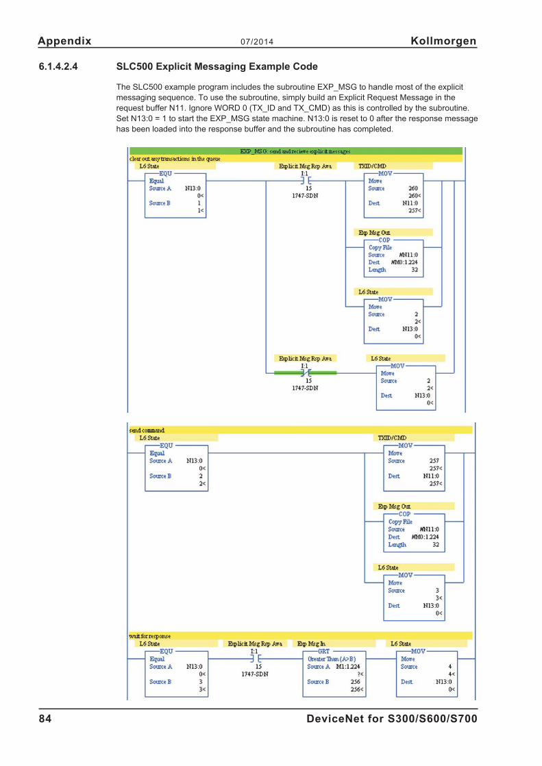
6.1.4.2.4 SLC500 Explicit Messaging Example Code
The SLC500 example program includes the subroutine EXP_MSG to handle most of the explicit
messaging sequence. To use the subroutine, simply build an Explicit Request Message in the
request buffer N11. Ignore WORD 0 (TX_ID and TX_CMD) as this is controlled by the subroutine.
Set N13:0 = 1 to start the EXP_MSG state machine. N13:0 is reset to 0 after the response message
has been loaded into the response buffer and the subroutine has completed.
84 DeviceNet for S300/S600/S700
Appendix 07/2014 Kollmorgen

6.1.5 Example 1: Simple Move
This example performs a simple operation, consisting of the following tasks:
1) Select positioning mode
2) Enable the servo amplifier
3) Home
4) Move one revolution
5) Wait until movement is complete
6) Set digital output 1 on
7) Delay 2 seconds
8) Set digital output 1off
9) Move back ½ revolution
DeviceNet for S300/S600/S700 85
Kollmorgen 07/2014 Appendix

6.1.5.1 Serial Command Sequence
This example may be executed manually from the serial terminal window in the amplifier setup soft-
ware with the following commands:
Command Description
OPMODE 8 Switch to position mode
EN Enable the S600
MH Move home
ACCR 10 acceleration time = 10ms
DECR 10 deceleration time = 10ms
O_V 60 target velocity = 60 RPM
O_P 1000 target position = 1000 counts (1 revolution)
O_C 10240
O_C2 256
command word = 0x2800 - user units for position and velocity; absolute move; interpret O_C2
secondary command word = 0x100 - use ACCR and DECR for this motion task
MOVE 0 Execute motion task 0 (wait for move to complete
O1 1 Set digital output 1 high (wait 2 seconds for desired delay)
O1 0 Set digital output 1 low
O_P 500 Set the target position to 500 counts (½ revolution)
MOVE 0 Execute motion task 0
Test the example manually before continuing to ensure that the servo amplifier is configured prop-
erly.
86 DeviceNet for S300/S600/S700
Appendix 07/2014 Kollmorgen

6.1.5.2 DeviceNet Command Sequence
DeviceNet CommandSerial Terminal
Verification
Set OpMode = Position_Mode
Explicit Msg Request: Service = 0x10, Class = 0x25, Instance=0x01,
Attribute = 0x03, Data = 0x00
OPMODE
8
Enable the amplifier
Polled I/O Command Assembly: set the Enable flag = 1 (byte 0, bit 7)
Word 0 = 0x2020_0080
Word 1 = 0x0000_0000
READY
1
Move Home
Explicit Msg Request: Service = 0x10, Class = 0x0F, Instance = 141
(MH command in the ascii reference), Attribute = 0x01, Data = 0x01
DRVSTAT
bit 0x2000 is set
Wait Until Homed – Read Amplifier Status Word
Explicit Msg Request: Service 0x0E, Class 0x25, Instance = 0x01, Attribute = 0x66
Home has comple-
ted
Set Acceleration Rate = 10
Polled I/O Command Assembly: use command 0x03
Word 0 = 0x2023_0080
Word 1 = 0x0000_000A
Toggle bit 0 high to load (Data Handshaking)
ACCR
10
Set Deceleration Rate = 10
Polled I/O Command Assembly: use command 0x04
Word 0 = 0x2024_0080
Word 1 = 0x0000_000A
Toggle bit 0 high to load (Data Handshaking)
DECR
10
Set Target Velocity = 60
Polled I/O Command Assembly: use command 0x02
Word 0 = 0x2022_0080
Word 1 = 0x0000_003C
Toggle bit 0 high to load (Data Handshaking)
O_V
60
Set Target Position = 1000
Polled I/O Command Assembly: use command 0x01
Word 0 = 0x2021_0080
Word 1 = 0x0000_03E8
Toggle bit 0 high to load and begin motion (Data Handshaking).
O_P
1000
O_C
10240 = 0x2800
(user units,
1 revolution)
Watch the Response Assembly – In Motion flag (byte 0, bit 0).
Wait until this bit transitions low (indicating that the move has completed).
The In Motion flag
should be high
whenever the drive
is in motion.
Set Digital Output 1 On
Explicit Msg Request: Service = 0x10, Class = 0x09, Instance = 0x01 (for output 1),
Attribute = 0x03, Data = 0x01
O1
1
Delay 2 seconds
(Set PLC timer to
delay for 2 se-
conds)
Set Digital Output 1 Off
Explicit Msg Request: Service = 0x10, Class = 0x09, Instance = 0x01 (for output 1),
Attribute = 0x03, Data = 0x00
O1
0
Set Target Position = 500
Polled I/O Command Assembly: use command 0x01
Word 0 = 0x2021_0080
Word 1 = 0x0000_01F4
Toggle bit 0 high to load and begin motion (Data Handshaking).
O_P
500
O_C
10240 = 0x2800
(user units,
- ½ revolution)
DeviceNet for S300/S600/S700 87
Kollmorgen 07/2014 Appendix

6.1.5.3 ControlLogix program
A ControlLogix program called S600_Example_1.ACD which implements this example is available
from the website. The example assumes that a DeviceNet scanner is installed in slot 1 and that an
servo amplifier at address 1 is mapped into the lowest words of the scanner.
To begin the example sequence, configure the amplifier as described in the section ‘Amplifier Setup
for the Examples’, download the program to the processor, enter run mode, and set Ex1State=1.
6.1.5.4 SLC500 program
A SLC500 program called S600_Example_1.RSS which implements this example is available from
the website. The example assumes that a DevieNet scanner is installed in slot 1 and that an servo
amplifier at address 1 is mapped into the lowest words of the scanner.
To begin the example sequence, configure the amplifier as described in the section ‘Amplifier Setup
for the Examples’, download the program to the processor, enter run mode, and set Ex1State
(N16:0) = 1.
6.2 Baud Rate Switch Settings
For servoamplifiers, the baud rate switch may be set to 0 (125 KBaud), 1 (250 KBaud) or 2 (500
KBaud). If the switch is set to a value greater than 2, the baud rate is configurable through the ter-
minal parameter DNBAUD and through DeviceNet. If the switch is set from 0 to 2, the baud rate
cannot be controlled with DNBAUD or DeviceNet.
6.3 MAC ID Switch Configuration
Values 0 to 63 are valid. If the switches are set to a value greater than 63, the MAC ID is
configurable through the terminal parameter DNMACID and through DeviceNet. If the switches are
set from 0 to 63, the MAC ID cannot be controlled with DNMACID or DeviceNet.
6.4 Network LED
The Network LED indicates the status of this device on the DeviceNet network.
Device state LED Details
Not powered / not online offDevice is not on–line. Either network power is off or the device has not
completed the Dup_MAC_ID test
Online, not connectedflashing
green
Device is on–line but has no connections in the established state. The
device has passed the Dup_MAC_ID test, is on–line, but has no establis-
hed connections to other nodes. This device is not allocated to a master.
Online, connected greenThe device is on–line and has connections in the established state. The
device is allocated to a Master.
Connection time-outflashing
redThe Polled I/O connection is in the timed-out state.
Critical link failure redThe device has detected an error that has rendered it incapable of com-
municating on the network (Duplicate MAC ID, or Bus–off).
6.5 Listing of DeviceNet Commands
This appendix cross-references DeviceNet messages (both Explicit Message class/instance/attrib-
ute mappings and Polled I/O Command/Response fields) to serial terminal commands. For informa-
tion of each serial command, look for the matching section in ascii.chm.
88 DeviceNet for S300/S600/S700
Appendix 07/2014 Kollmorgen

6.5.1 Data Types
Type Description Width (bytes) Min Max
BOOL Boolean 1
SINT Short Integer 1 -128 127
BYTE bit string - 8 bits 1
USINT Unsigned Short Integer 1 0 255
INT Integer 2 -32768 32767
UINT Unsigned Integer 2 0 655351
WORD bit string - 16-bits 2
DINT Double Integer 4 -231 231 -1
UDINT Unsigned Double Integer 4 0 232-1
DWORD bit string - 32-bits 4
LINT Long Integer 8 -263 263-1
ULINT Unsigned Long Integer 8 0 264-1
LWORD bit string - 64-bits 8
EPATH DeviceNet path segments variable
6.5.2 Explicit Messages
Services: Reset=0x05, Get=0x0E, Set=0x10
Classes: 0x01=Identity Object, 0x24=Position Controller Supervisor, 0x25=Position Controller
Object, 0x26=Block Sequencer, 0x27=Command Block, 0x0F=Parameter Object
Name Cls Inst Attr Srvc Data Notes
Identity Object
Reset 0x01 0x01 0x00 R none Set value=1 to restart the amplifier. COLDSTART.
Default 0x01 0x01 0x01 R noneSet value=1 to load default parameters and res-
tart. RSTVAR, SAVE, COLDSTART.
Serial Number 0x01 0x01 0x06 G UDINT SERIALNO
Position Controller Supervisor Object
General Fault 0x24 0x01 0x05 G BOOL
=1 if any amplifier faults (ERRCODE). Also set on
warnings for n3 (position error), n8 (bad motion
task), n9 (reference point not set)
Clear Faults 0x24 0x01 0x65 G/S BOOL Set value=1 to clear faults. CLRFAULT.
Error Code 0x24 0x01 0x64 G DINTERRCODE. Returns the hex value of the error
code.
Position Controller Object
Mode 0x25 0x01 0x03 G/S USINT0=Position (OPMODE 8). 1= velocity (OPMODE
0). 2=Torque (OPMODE 2).
Target Position 0x25 0x01 0x06 G/S DINT
O_P. Sets O_C bits 0x2800 and O_C2 bits 0x100,
units are SI and ACCR/DECR override
O_ACC1/O_DEC1.
Target Velocity 0x25 0x01 0x07 G/S DINT O_V. Units determined by amplifier configuration.
Acc 0x25 0x01 0x08 G/S DINTVelocity Mode: ACC. Position Mode: ACCR. Units
set by ACCUNIT,PGEARI.
Dec 0x25 0x01 0x09 G/S DINTVelocity Mode: DEC. Position Mode: DECR. Units
set by ACCUNIT,PGEARI.
Incremental Flag 0x25 0x01 0x0a G/S BOOL O_C bit 0. 0->ABS, 1->INCR.
Load/Profile
Handshake0x25 0x01 0x0b G/S BOOL
Get: 1 if in motion. Set 1 to move (type depends
on Mode - attr 3).
in position 0x25 0x01 0x0c G BOOL INPOS
Actual Position 0x25 0x01 0x0d G/S DINTGet: read current position (PFB). Set: redefine po-
sition. ROFFS=X, NREF=0, MH
Actual Velocity 0x25 0x01 0x0e G DINT abs(PV)
Enable 0x25 0x01 0x11 G/S BOOL EN
Smooth Stop 0x25 0x01 0x14 G/S BOOL STOP. DECR is rate. Get returns 0.
Hard Stop 0x25 0x01 0x15 G/S BOOL Emergency stop. DECSTOP is rate. Get returns 0.
DeviceNet for S300/S600/S700 89
Kollmorgen 07/2014 Appendix

Name Cls Inst Attr Srvc Data Notes
Jog Velocity 0x25 0x01 0x16 G/S DINT
J. Positive value – direction depends on Direction
attr23 Units determined by amplifier configuration.
Used only in Velocity Mode.
Direction 0x25 0x01 0x17 G/S BOOL
Get: current direction of motion (not the flag). S:
direction flag for J. 1->pos direction. 0->neg direc-
tion
Reference Directi-
on0x25 0x01 0x18 G/S BOOL
DIR (inverse). 1=pos, 0=neg (0 -> CW is positive).
Can only set when amplifier is disabled. You must
save and restart the amplifier after setting this va-
riable.
Torque 0x25 0x01 0x19 G/S DINT
New torque value (set Load bit - attr 11 - to move).
Internal counts. 3280 = peak torque. Similar to the
T command, except the new torque command isn’t
executed until the Load bit is set.
Save parameters 0x25 0x01 0x65 G/S BOOLSAVE. Write 1 to save parameters to EPROM. Get
returns 0.
Drive Status 0x25 0x01 0x66 G DINT DRVSTAT
Trajectory Status 0x25 0x01 0x67 G DINT TRJSTAT
Block Sequencer Object
Block 0x26 0x01 0x01 G/S USINT1-255. Block number to execute (ORDER# for
MOVEx).
Block Execute 0x26 0x01 0x02 G/S BOOLSet to begin block execution. Reads 1 while exe-
cuting a block and 0 when complete. MOVE x.
Current Block 0x26 0x01 0x03 G/S USINTNumber of currently executing block. Reads 0 on
jog. TASKNUM.
Block Fault 0x26 0x01 0x04 G/S BOOLSet when a block error occurs. Reset when Block
Fault Code is read.
Block Fault Code 0x26 0x01 0x05 G/S BOOL
0=no fault, 1 = invalid or empty block data, 2 =
command time out (Wait Equals), 3 = execution
fault.
Counter 0x26 0x01 0x06 G/S DINT (positive) counter for block looping. M LOOPCNT.
Command Block Object (all)
Block Type 0x27 0x01-0xff 0x01 G/S USINT
Command to execute, e.g. 0x01=Modify Attribute
(see following sections). The value of Block Com-
mand determines the format of attributes 3-7. The
block command is stored in the 2 low bytes of
O_C2 (see following sections for mapping of Block
Command value into O_C2). For motion tasks, bit
0x100 in O_C2 is set so that ACCR and DECR are
used for the acceleration and deceleration rates.
Setting the block command also modifies O_C -
sets 0x800 (extended task type bit) for most tasks
and 0x2800 for motion tasks.
Block Link # 0x27 0x01-0xff 0x02 G/S USINT
O_FN - Instance number of the next block to exe-
cute when this block is done. 0 means no following
task.
Command Block Object (with Block Command=1 Modify Attribute)
Modify Attribute - set the value of any DeviceNet accessible attribute. Setting Block Command (attribute 1) =
Modify Attribute will also set O_C bit 0x800 and O_C2=6.
Class 0x27 0x01-0xff 0x03 G/S USINTClass to access (e.g. 0x25 for Position Controller
Object). Stored in the upper byte of O_ACC1.
Instance 0x27 0x01-0xff 0x04 G/S USINT Instance to access. Stored in O_DEC1.
Attribute 0x27 0x01-0xff 0x05 G/S USINTAttribute to access (must be settable). Stored in
the lower byte of O_ACC1.
Data 0x27 0x01-0xff 0x06 G/S DINT New attribute data. Stored in O_P.
Command Block Object (with Block Command=2 Wait for Parameter Value)
Wait for parameter value - delay until a DeviceNet accessible attribute equals a desired value. Setting Block
Command (attribute 1) = 2 will also set O_C bits 0x880 and O_C2=2.
Class 0x27 0x01-0xff 0x03 G/S USINTClass to access (e.g. 0x25 for Position Controller
Object). Stored in the upper byte of O_ACC1.
Instance 0x27 0x01-0xff 0x04 G/S USINT Instance to access. Stored in O_DEC1.
Attribute 0x27 0x01-0xff 0x05 G/S USINTAttribute to access (must be settable). Stored in
the lower byte of O_ACC1.
90 DeviceNet for S300/S600/S700
Appendix 07/2014 Kollmorgen

Name Cls Inst Attr Srvc Data Notes
Time-out 0x27 0x01-0xff 0x06 G/S DINTMaximum time to wait in ms. Fault if time-out is
reached. 0 = no timeout. Stored in O_FT.
Compare Data 0x27 0x01-0xff 0x07 G/S DINT Value to wait for. Stored in O_P.
Command Block Object (with Block Command=3 Greater-Than Test)
Greater-than test - Test the value of a DeviceNet accessible attribute and branch to an alternate block if the at-
tribute value is greater than the test value. Setting Block Command (attribute 1) = 3 will also set O_C bit 0x800
and O_C2=3.
Class 0x27 0x01-0xff 0x03 G/S USINTClass to access (e.g. 0x25 for Position Controller
Object). Stored in the upper byte of O_ACC1.
Instance 0x27 0x01-0xff 0x04 G/S USINT Instance to access. Stored in O_DEC1.
Attribute 0x27 0x01-0xff 0x05 G/S USINTAttribute to access (must be settable). Stored in
the lower byte of O_ACC1.
Alternate Link
Number0x27 0x01-0xff 0x06 G/S USINT Block to branch to if true. Stored in O_DEC2.
Compare Data 0x27 0x01-0xff 0x07 G/S DINT
If the Attribute is greater than Compare Data,
ignore the normal link (attribute 2) and branch to
Alternative Link (attribute 6). Stored in O_P.
Command Block Object (with Block Command=4 Less-Than Test)
Less-than test - Test the value of a DeviceNet accessible attribute and branch to an alternate block if the attri -
bute value is less than the test value. Setting Block Command (attribute 1) = 4 will also set O_C bit 0x800 and
O_C2=4.
Class 0x27 0x01-0xff 0x03 G/S USINTClass to access (e.g. 0x25 for Position Controller
Object). Stored in the upper byte of O_ACC1.
Instance 0x27 0x01-0xff 0x04 G/S USINT Instance to access. Stored in O_DEC1.
Attribute 0x27 0x01-0xff 0x05 G/S USINTAttribute to access (must be settable). Stored in
the lower byte of O_ACC1.
Alternate Link
Number0x27 0x01-0xff 0x06 G/S USINT Block to branch to if true. Stored in O_DEC2.
Compare Data 0x27 0x01-0xff 0x07 G/S DINT
If the Attribute is less than Compare Data, ignore
the normal link (attribute 2) and branch to Alterna-
tive Link (attribute 6). Stored in O_P.
Command Block Object (with Block Command=5 Decrement Counter)
Decrement Counter - This block decrements the global counter in the Command Block Sequencer object. No
additional attributes are defined for this command type. Setting Block Command (attribute 1) = 5 will also set
O_C bit 0x800 and O_C2=9.
Command Block Object (with Block Command=6 Delay)
Delay - This block causes the sequencer to delay for a given number of milliseconds before continuing with the
next block. The block must have a Block Link in attribute 2. Setting Block Command=6 will also set O_C bits
0x880 and O_C2=1.
Delay 0x27 0x01-0xff 0x03 G/S DINT Time to delay in ms. Stored in O_FT.
Command Block Object (with Block Command=8 Trajectory)
Trajectory - execute a positioning move. Setting Block Command=8 will also set O_C bit 0x3800 (SI units, ex-
tended task) and O_C2=0x100 (use global acceleration and deceleration rates).
Target Position 0x27 0x01-0xff 0x03 G/S DINT O_P
Target Velocity 0x27 0x01-0xff 0x04 G/S DINT O_V
Incremental 0x27 0x01-0xff 0x05 G/S BOOLO_C bit 0. 0->absolute move, 1->incremental
move.
Command Block Object (with Block Command=9 Velocity Change)
Velocity Change - execute a velocity profile. Setting Block Command=9 will also set O_C2=0x165 and O_C
bits 0x3800. This type of block cannot have a next block link since the velocity profile doesn’t have a definite
end.
Target Velocity 0x27 0x01-0xff 0x03 G/S DINT O_V
Parameter Object
The instance number in the parameter object corresponds to the DPR number specified in the ASCII serial-ter-
minal command reference for drive parameters. Only parameters 1-255 are accessible.
Parameter Value 0x0F 0x01-0xFF 0x01 G/S type
Actual value of the parameter. The value is
read-only if bit 4 of attr#4 (descriptor-ReadOnly bit)
is 1.
Descriptor 0x0F 0x01-0xFF 0x04 G WORD Read-only if bit 0x10 is set.
Data Size 0x0F 0x01-0xFF 0x06 G USINT Length of the data in bytes.
DeviceNet for S300/S600/S700 91
Kollmorgen 07/2014 Appendix
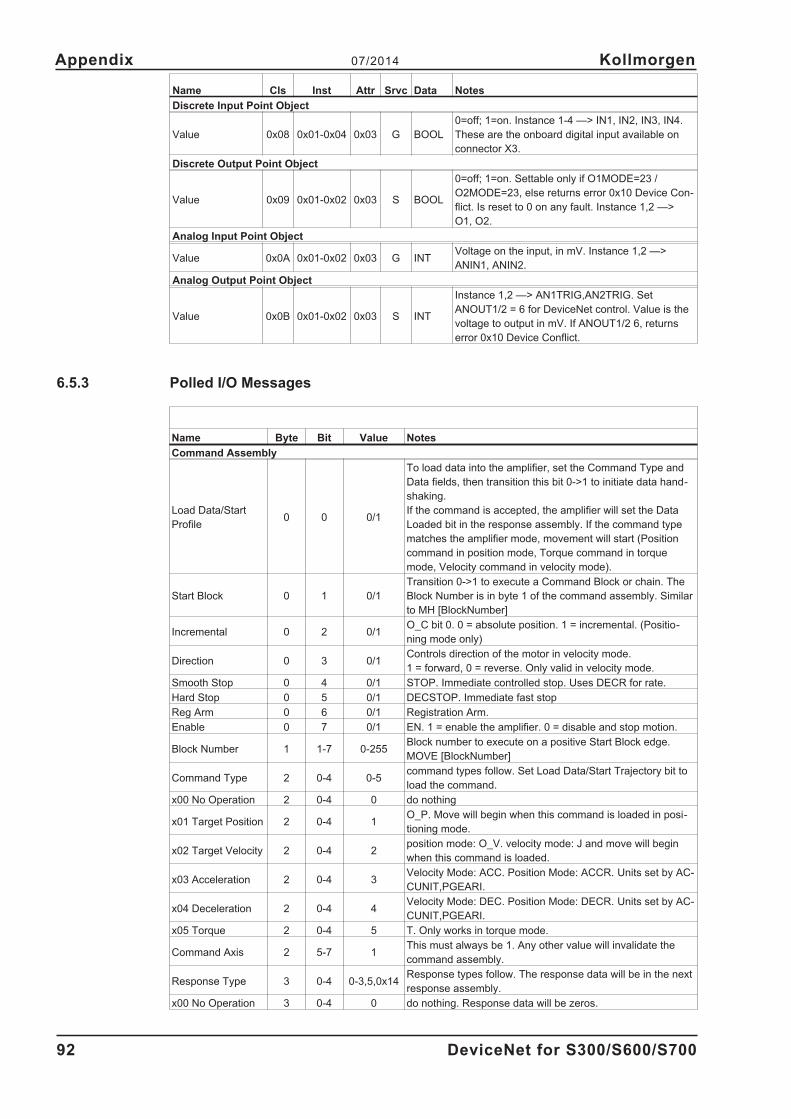
Name Cls Inst Attr Srvc Data Notes
Discrete Input Point Object
Value 0x08 0x01-0x04 0x03 G BOOL
0=off; 1=on. Instance 1-4 —> IN1, IN2, IN3, IN4.
These are the onboard digital input available on
connector X3.
Discrete Output Point Object
Value 0x09 0x01-0x02 0x03 S BOOL
0=off; 1=on. Settable only if O1MODE=23 /
O2MODE=23, else returns error 0x10 Device Con-
flict. Is reset to 0 on any fault. Instance 1,2 —>
O1, O2.
Analog Input Point Object
Value 0x0A 0x01-0x02 0x03 G INTVoltage on the input, in mV. Instance 1,2 —>
ANIN1, ANIN2.
Analog Output Point Object
Value 0x0B 0x01-0x02 0x03 S INT
Instance 1,2 —> AN1TRIG,AN2TRIG. Set
ANOUT1/2 = 6 for DeviceNet control. Value is the
voltage to output in mV. If ANOUT1/2 6, returns
error 0x10 Device Conflict.
6.5.3 Polled I/O Messages
Name Byte Bit Value Notes
Command Assembly
Load Data/Start
Profile0 0 0/1
To load data into the amplifier, set the Command Type and
Data fields, then transition this bit 0->1 to initiate data hand-
shaking.
If the command is accepted, the amplifier will set the Data
Loaded bit in the response assembly. If the command type
matches the amplifier mode, movement will start (Position
command in position mode, Torque command in torque
mode, Velocity command in velocity mode).
Start Block 0 1 0/1
Transition 0->1 to execute a Command Block or chain. The
Block Number is in byte 1 of the command assembly. Similar
to MH [BlockNumber]
Incremental 0 2 0/1O_C bit 0. 0 = absolute position. 1 = incremental. (Positio-
ning mode only)
Direction 0 3 0/1Controls direction of the motor in velocity mode.
1 = forward, 0 = reverse. Only valid in velocity mode.
Smooth Stop 0 4 0/1 STOP. Immediate controlled stop. Uses DECR for rate.
Hard Stop 0 5 0/1 DECSTOP. Immediate fast stop
Reg Arm 0 6 0/1 Registration Arm.
Enable 0 7 0/1 EN. 1 = enable the amplifier. 0 = disable and stop motion.
Block Number 1 1-7 0-255Block number to execute on a positive Start Block edge.
MOVE [BlockNumber]
Command Type 2 0-4 0-5command types follow. Set Load Data/Start Trajectory bit to
load the command.
x00 No Operation 2 0-4 0 do nothing
x01 Target Position 2 0-4 1O_P. Move will begin when this command is loaded in posi-
tioning mode.
x02 Target Velocity 2 0-4 2position mode: O_V. velocity mode: J and move will begin
when this command is loaded.
x03 Acceleration 2 0-4 3Velocity Mode: ACC. Position Mode: ACCR. Units set by AC-
CUNIT,PGEARI.
x04 Deceleration 2 0-4 4Velocity Mode: DEC. Position Mode: DECR. Units set by AC-
CUNIT,PGEARI.
x05 Torque 2 0-4 5 T. Only works in torque mode.
Command Axis 2 5-7 1This must always be 1. Any other value will invalidate the
command assembly.
Response Type 3 0-4 0-3,5,0x14Response types follow. The response data will be in the next
response assembly.
x00 No Operation 3 0-4 0 do nothing. Response data will be zeros.
92 DeviceNet for S300/S600/S700
Appendix 07/2014 Kollmorgen

Name Byte Bit Value Notes
x01 Actual Position 3 0-4 1 PFB
x02 Commanded
Position3 0-4 2 PTARGET
x03 Actual Velocity 3 0-4 3 abs(PV). Steps/s. Absolute value of velocity.
x05 Torque 3 0-4 5 I
x14 Assembly Error 3 0-4 0x14
Error code in response assembly: bytes 4-5=error code,
6-7=mirror command bytes 2-3.
ERROR CODES... Less than 8 bytes: x13 ff. Unsupported
command: x08 01. Unsupported Response: x08 02. Unsup-
ported command axis: x05 01. Unsupported response axis:
x05 02. Get unsupported attribute: x14 02. Set unsupported
attribute: x14 01. Set unsettable attribute: x0E FF. Set invalid
value: x09 FF.
Response Axis 3 5-7 1This must always be 1. Any other value will invalidate the
command assembly.
Command Data 4-7Data depends on Command Type. Data bytes are in reverse
order - the least significant byte is first.
Response Assembly
Profile in progress 0 0 0/11 = a move has been commanded and is not complete.
DRVSTAT bit 0x10000
Block in execution 0 1 0/1 1 = a block is in execution. Block number given in byte 1.
in position 0 2 0/1 INPOS. 1 = in position
General Fault 0 3 0/1 1 = alarm. Faults, Warnings n3, n8, n9. ERRCODE.
Current Direction 0 4 0/1 Current Direction. 1 = Fwd. V positive or negative.
Home Flag 0 5 0/11=off the flag, 0=on the flag. Level of home input. DRVSTAT
bit 0x40000
Reg Level 0 6 0/1 Registration input level. IN2MODE must = 26
Enable 0 7 0/1 1 = enabled. READY.
Executing Block # 1 0-7 0-255Block currently in execution. 0=no block executing. TAS-
KNUM.
Fault Input 2 0 0/1
1 = Fault Input is active. Using Emergency Stop inputs.
Check for input with INxMODE=27 and input level low (active
level low is fault).
Positive HW Limit 2 1 0/1 DRVSTAT bit 0x200. 1=active.
Negative HW Limit 2 2 0/1 DRVSTAT bit 0x400. 1=active.
Positive Software
Limit2 3 0/1 DRVSTAT bit 0x40. 1=active
Negative Software
Limit2 4 0/1 DRVSTAT bit 0x20. 1=active
Following Error 2 5 0/1 Following Error. DRVSTAT bit 0x04.
Block Fault 2 6 0/1Error executing a block. 1 = Fault. Read Block Sequencer
Object attr#5 to clear.
Load Complete 2 7 0/1Load Complete. Command data loaded successfully. Reset
when Load/Start bit is low.
Response Type 3 0-4 0-3,5,0x14Echoes Response Type from Command Assembly. See des-
cription above.
Response Axis 3 5-7 1 Echoes Response Axis from Command Assembly.
Response Data 4-7Data depends on Response Type. Data bytes are in reverse
order - the least significant byte is first.
6.6 Default Input/Output Configuration
For the servo amplifier, the following input configuration is applicable:
O1MODE=23 (DeviceNet control of digital output 1)
O2MODE=23 (DeviceNet control of digital output 2)
ANOUT1=6 (DeviceNet control of analog output 1)
ANOUT1=6 (DeviceNet control of analog output 1)
DeviceNet for S300/S600/S700 93
Kollmorgen 07/2014 Appendix

6.7 Error Messages
DeviceNet error messages are received when a command assembly or explicit request message
cannot be handled successfully by the amplifier. This is often caused by either an invalid message
or an invalid amplifier state.
The servo amplifier transmits an error response assembly in reply to a bad command assembly.
Response type 0x14 is loaded in the Response Assembly Type field and the error codes are loaded
in bytes 4-5. See section 5.2.6 for more information.
The servo amplifier will transmit an error explicit response message in reply to a bad explicit request
message. This response will have service code 0x94 and the error codes in the first two data bytes.
Error Code (hex) Additional Code (hex) DeviceNet Error
0 FF NO ERROR
2 FF RESOURCE_UNAVAILABLE
5 FF PATH_UNKNOWN
5 1 COMMAND_AXIS_INVALID
5 2 RESPONSE_AXIS_INVALID
8 FF SERVICE_NOT_SUPP
8 1 COMMAND_NOT_SUPPORTED
8 2 RESPONSE_NOT_SUPPORTED
9 FF INVALID_ATTRIBUTE_VALUE
B FF ALREADY_IN_STATE
C FF OBJ_STATE_CONFLICT
D FF OBJECT_ALREADY_EXISTS
E FF ATTRIBUTE_NOT_SETTABLE
F FF ACCESS_DENIED
10 FF DEVICE_STATE_CONFLICT
11 FF REPLY_DATA_TOO_LARGE
13 FF NOT_ENOUGH_DATA
14 FF ATTRIBUTE_NOT_SUPP
15 FF TOO_MUCH_DATA
16 FF OBJECT_DOES_NOT_EXIST
17 FF FRAGMENTATION_SEQ_ERR
20 FF INVALID_PARAMETER
94 DeviceNet for S300/S600/S700
Appendix 07/2014 Kollmorgen

6.8 Index
DeviceNet for S300/S600/S700 95
Kollmorgen 07/2014 Appendix
A Abbreviations . . . . . . . . . . . . . . . . . . 8
Additional documentation . . . . . . . . . . . . 7
B Basic features . . . . . . . . . . . . . . . . . . 9
C Communication faults . . . . . . . . . . . . . 16
D Data transfer functions . . . . . . . . . . . . . 9
Data types . . . . . . . . . . . . . . . . . . . 21DeviceNet bus cable . . . . . . . . . . . . . . 13
E Error codes. . . . . . . . . . . . . . . . . . . 23
I I/O response . . . . . . . . . . . . . . . . . . 64
Installation . . . . . . . . . . . . . . . . . . . 11
M Motion objects . . . . . . . . . . . . . . . . . 18
O Object class
Block sequencer . . . . . . . . . . . . . . 33Command block . . . . . . . . . . . . . . 35Connection (explicit) . . . . . . . . . . . . 51Connection (polled I/O) . . . . . . . . . . 52DeviceNet . . . . . . . . . . . . . . . . . 50Identity . . . . . . . . . . . . . . . . . . . 49Message router . . . . . . . . . . . . . . 50Position controller . . . . . . . . . . . . . 25Position controller supervisor . . . . . . . 23
P Polled I/O. . . . . . . . . . . . . . . . . . . . 53
Position controller . . . . . . . . . . . . . . . 17Positioning functions . . . . . . . . . . . . . . 9
S Setup . . . . . . . . . . . . . . . . . . . . . . 16
Setup functions . . . . . . . . . . . . . . . . . 9Supervisor attributes . . . . . . . . . . . . . . 23Symbols . . . . . . . . . . . . . . . . . . . . . 8System requirements . . . . . . . . . . . . . . 8
T Target group. . . . . . . . . . . . . . . . . . . 7
Transmission procedure. . . . . . . . . . . . . 9Transmission rate . . . . . . . . . . . . . . . . 9
U Use as directed . . . . . . . . . . . . . . . . . 8
Service
We are committed to quality customer service. In order to serve in the most effective way,
please contact your local sales representative for assistance.
If you are unaware of your local sales representative, please contact the Customer Support.
Europe
KOLLMORGEN Customer Support Europe
Internet www.kollmorgen.com
E-Mail [email protected]
Tel.: +49 (0)2102 - 9394 - 0
Fax: +49 (0)2102 - 9394 - 3155
KOLLMORGEN European
UK Website Product WIKI
North America
KOLLMORGEN Customer Support North America
Internet www.kollmorgen.com
E-Mail [email protected]
Tel.: +1 - 540 - 633 - 3545
Fax: +1 - 540 - 639 - 4162
KOLLMORGEN
US Website
Asia
KOLLMORGEN
Internet www.kollmorgen.com
E-Mail [email protected]
Tel: +86 - 400 666 1802
Fax: +86 - 10 65 15 0263
KOLLMORGEN
CN Website