Embed Size (px)
Citation preview
January 1, 2002 / Vol. 27, No. 1 / OPTICS LETTERS 7
Deviation from Snell’s law for beams transmitted near thecritical angle: application to microcavity lasers
H. E. Tureci and A. Douglas Stone
Department of Applied Physics, P.O. Box 208284, Yale University, New Haven, Connecticut 06520-8284
Received July 30, 2001
We show that when a narrow beam is incident upon a dielectric interface near the critical angle for totalinternal ref lection it will be transmitted into the far field with an angular def lection from the directionpredicted by Snell’s law, because of a phenomenon that we call “Fresnel filtering.” This effect can be quitelarge for the parameter range that is relevant to dielectric microcavity lasers. © 2002 Optical Society ofAmerica
OCIS codes: 140.3410, 140.4780, 230.3990, 230.5750, 260.2110, 260.5740.
A promising approach to making high-Q optical micro-cavities and microlasers is to base them on totally in-ternally ref lected modes of dielectric microstructures.This approach is currently under intense investiga-tion with resonators and lasers based on a range ofshapes: disks, cylinders, spheres,1 deformed cylin-ders and spheres,2 – 7 squares,8 and hexagons.9 Manydifferent mode geometries, e.g., whispering-gallerymodes,1 bow-tie modes,2,3 and triangle6,7 and square8
modes, have been observed in such resonators. Typi-cally these modes correspond to ray trajectories thatare incident upon the boundary of the resonator aboveor at the critical angle to achieve adequately highQ values and may correspond to periodic ray orbits(POs), which are stable, unstable, or marginally stable.The natural method for predicting how such a modewill emit or scatter light is to apply Snell’s law to theray orbit and follow the refracted ray into the far field.For a ray that is incident at the critical angle, thismethod would imply emission in the direction tangentto the boundary at the emission point. However, inseveral recent experiments, very large deviations fromthis expectation were observed.2,7 We show belowthat such observations may be explained as arisingfrom the angular spread in the resonant mode aroundthe PO. The variation in Fresnel ref lection with inci-dent angle filters out the angular components, whichare totally internally ref lected and preferentiallytransmits those that are far from totally internallyref lected, leading to a net angular rotation of theoutgoing radiation from the tangent direction. Wecall this effect Fresnel filtering (FF).
The effects occurs for a bounded beam with anarbitrary cross section that is incident from a semi-infinite medium of index n into vacuum, although itwill be quantitatively altered in a resonator becauseof the curvature and (or) the finite length of theboundary. We thus begin with the planar example,which we solve analytically, before presenting nu-merical results for quadrupolar asymmetric resonantcavities (ARCs).10 There is a large body of literatureon ref lection of a beam from a dielectric interfacenear or above the critical angle, as the ref lected beamexhibits the Goos–Hänchen lateral shift as well as
0146-9592/02/010007-03$15.00/0 ©
other nonspecular phenomena.11 However, only afew of these works addressed the transmission12,13 ofthe beam, and they tended to focus on the evanescenteffects in the near f ield; none appear to have identifiedthe FF effect.
For simplicity, we consider a two-dimensional planarinterface that separates two semi-infinite regions witha relative index of refraction, n. Consider a beam Eiathat is incident from the denser region, with a centralincidence angle ui. We take the beam to be Gaussian,with a minimum beam waist w (which we use to scaleall lengths) at a distance z0 from the interface. Thebasic effect is independent of the nature of the inputbeam as long as it is focused and has significantangular spread. The corresponding Snell emissionangle ue (which is in general complex) is given byn sin ui � sin ue. Si : �xi, zi� and Se : �xe, ze� refer tocoordinates tied to the incident and refracted beams,respectively (see the inset of Fig. 1). We considerlinearly polarized beams; the corresponding beam
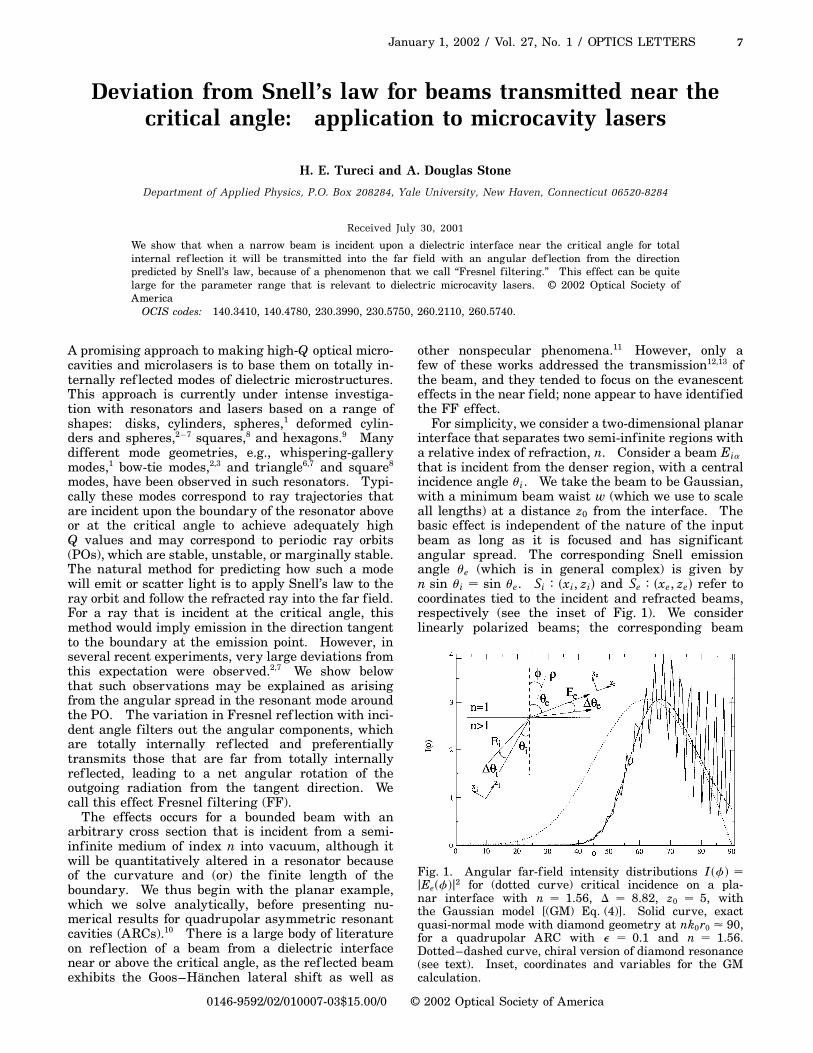
Fig. 1. Angular far-f ield intensity distributions I �f� �jEe�f�j2 for (dotted curve) critical incidence on a pla-nar interface with n � 1.56, D � 8.82, z0 � 5, withthe Gaussian model [(GM) Eq. (4)]. Solid curve, exactquasi-normal mode with diamond geometry at nk0r0 � 90,for a quadrupolar ARC with e � 0.1 and n � 1.56.Dotted–dashed curve, chiral version of diamond resonance(see text). Inset, coordinates and variables for the GMcalculation.
2002 Optical Society of America

8 OPTICS LETTERS / Vol. 27, No. 1 / January 1, 2002
fields, Ea , a � TM, TE, then denote the electric (TM)and the magnetic (TE) f ields normal to the plane ofincidence.
In the angular-spectrum representation,14 theincident beam in Si coordinates will consist of asuperposition of plane waves of the same frequencyv with a Gaussian distribution of transverse wavevectors nkos, where s � sin Dui, k0 � v�c0 is the wavevector in vacuum and Dui is the deviation angle of theplane-wave component from ui:
Eia�xi, zi� �E0D
2p
p
Z `
2`
ds exp∑2
µD
2
∂2
s2
1 iD�sxi 1 czi�∏, (1)
where c �p1 2 s2 and the dimensionless width pa-
rameter D � nk0w.The beam on the z . 0 side of the interface in po-
lar coordinates �r,f� attached to the interface (afterrefraction) is then given by the integral:
Eea�r,f� �E0D
2p
p
Z `
2`
dsTa�s�G�s�
3 exp∑i
D
nr cos�f 2 ue 2 Due�
∏. (2)
Here Due is obtained from n sin�ui 1 Dui� � sin�ue 1Due�, and G �s� is given by
G�s� � exp∑2
µD
2
∂2
s2 1 iDp1 2 s2 z0
∏. (3)
Evaluating this integral in the asymptotic far f ield�r ! `� by use of the saddle-point method, we obtainour GM of the FF effect:
Eea�f� �E0Dr2i
D
nr
q1 2 s20 cos fpn2 2 sin2f
3 Ta�s0�G�s0�expµi
D
nr
∂, (4)
where the transmission functions, evaluated at therelevant saddle point, s0�f� � 1/n�sin f cos ui 2
sin ui
qn2 2 sin2f �, are given by
Ta�s0�f�� �2n
pn2 2 sin2f
mpn2 2 sin2f 1 n2
p1 2 sin2f
. (5)
Here, m � 1 �n� for a � TE �TM�. The relevant saddlepoint arises from setting to zero the derivative of thecosine in the exponent of Eq. (2); this saddle-pointvalue selects the angular component, which refracts inthe observation direction, f, by Snell’s law. However,the amplitude factor obtained by Gaussian integrationaround the saddle point shifts the maximum of theoutgoing beam away from the Snell direction. As
noted above, the effect occurs for narrow beams withan arbitrary (non-Gaussian) wave-vector distributionB�s�; in such a case, the factor G �s0� in Eq. (4) isreplaced with B �s0� (see, e.g., Ref. 8.
Equation (4) gives the angular beam profile in thefar f ield, which is none zero for any incident angle ui,even ui . uc � sin21�1�n�. The key point is that theangular maximum of this outgoing beam, fmax, is ingeneral not at the angle ue predicted by applicationof Snell’s law to the central incident beam direction,ui. Instead, because of the unequal transmission ofthe different angular components, the beam directionis shifted by an angle DuFF that corresponds to lessrefraction than expected from Snell’s law. This angu-lar def lection can be quite large for incidence near ucin typical microcavity resonators; in Fig. 1, the dottedcurve is the result of Eq. (4) for critical incidence, forwhich the Snell angle is f � 90± but fmax � 62±, givingDu
cFF � 28±. The far-field peak shift, DuFF , depends
on the beam width, D, and on n; analysis of the sta-tionary phase solution gives the result that, at ui � uc,
DucFF � �2�tan uc�1�2D21�2, (6)
which predicts that DucFF � 30± for the parameters
of Fig. 1.Two technical points are in order here: First, there
may be branch-cut contributions to integration alongthe steepest descent path, as found in analysis of theref lected beam. Such contributions are subdominantwith respect to the f irst-order asymptotic term derivedin Eq. (4). Second, there is another saddle point, s̃0 �cos �ui�, which corresponds to angular components withgrazing incidence to the interface. Because the Fres-nel transmission factor vanishes for such components,s̃0 contributes to the integral only at order O �r23�2�and is important only very near f � p�2. We neglectthis contribution here.
Clearly, the same FF effect will occur in emissionfrom dielectric resonators, and its magnitude will besimilar to the planar case when the typical radius ofcurvature is much larger than w. As an example, weinvestigate the effect of FF on the far-field emissionpattern of quadrupolar ARCs,2,6,7,10 dielectric cylinderswith a cross section given by r�fw� � r0�1 1 e cos 2fw�.We study the exact numerically generated quasi-boundTM modes of a resonator with 10% �e � 0.1� defor-mation for different values of the refractive index n,focusing on resonances based on the stable four-bounce(diamond) PO. The numerical method used is a vari-ant of the “scattering quantization” for billiards.15 If,as in this case, the relevant orbit is stable and weneglect leakage, then it is possible to construct ap-proximate modes that are piecewise Gaussian on eachsegment of the PO. One find that the effective beamwaist in each segment will scale as D � j
pnk0r0 ,
where j is a constant that is dependent only on the sta-bility-matrix eigenvectors of that particular segmentand k0 is the real part of the quantized eigenvalueof the mode. In Fig. 2(a) we plot one representativequasi-bound mode at n � 1.56 (the index is chosen sothat ui � uc for this mode); the corresponding far-fieldangular intensity is plotted in Fig. 1.

January 1, 2002 / Vol. 27, No. 1 / OPTICS LETTERS 9
Fig. 2. (a) Field-intensity plot (gray scale) for a diamondresonance of the quadrupole at critical incidence for thepoints at fw � 0, p, calculated numerically at nk0r0 � 90,n � 1.56, and e � 0.1. Note that there is negligibleemission from the upper and lower bounce points atfw � 690± because they are above the critical angle.(b) Chiral counterpart of this exact resonance.
Fig. 3. Comparison of peak angular far-field valuesfmax for varying critical angle uc � sin21�1�n�. Dia-monds, exact resonances at nk0r0 � 90; solid curve, GMcalculation with D � 8.82; dashed curve, Snell’s lawprediction: sin fmax � n sin ui, where ui � 39±. Du
cFF ,
deviation from Snell’s law at uc � ui.
One can see the rapid oscillations due to interfer-ence, but in Fig. 1 it is clear that the maximum of theintensity is displaced from f � 90±as expected becauseof FF. To compare the size of the effect with that ofthe GM it is convenient to eliminate the interferenceby calculating the chiral resonance, shown in Fig. 2(b).This is the original resonance with the negativeangular-momentum components projected out, hencegenerating a unidirectional beam. Plotting this chiralresonance in Fig. 1 (dotted–dashed line) gives thediamond resonance a smooth envelope without theoscillations. Regarding this chiral resonance as abeam that is incident at fw � 0 on the boundary, withan angle of incidence ui � 39±, we can compare theFF shift with that of the GM. From Fig. 1, one cansee that the resonance emission peaks at fmax � 66±,whereas the GM gives a similar envelope that isslightly shifted, with fmax � 62±.
To evaluate systematically the FF effect, we havecalculated the far-field peaks of the set of diamondresonances while varying the index of refraction, so
that the critical angle is scanned through the PO in-cidence angle ui � 39±. To remain as close as possibleto our GM with fixed D, we have chosen the resonancesso that nk0r0 is approximately constant. In Fig. 3, thenumerical resonance peak is compared with the calcu-lated value fmax from Eq. (4) and with fmax predictedby Snell’s law. One can see that maximum deviationtakes place at uc.
In conclusion, we have shown that the transmissiondirection of a narrow beam through a plane dielectricinterface can be quite different from the direction pre-dicted by application of Snell’s law to the incident beamdirection. This effect is important for predicting theemission patterns from resonances based on POs inmicrocavities. This is true even when the size of theresonator, r0, is much larger than the wavelength, andone might have expected ray optics to be quite good.Specifically, the effective beam waist for stable reso-nances scales as D ~
pnk0r0 , so from Eq. (6) the devia-
tion angle at critical incidence ucFF ~ �nk0r0�21�4 and
hence may be large for nk0r0 � 102 103, as in recentexperiments on semiconductor ARC lasers.2,3,7
We acknowledge helpful discussions with H.Schwefel, N. Rex, and R. K. Chang. This work wassupported by National Science Foundation grantDMR-0084501. H. Tureci’s e-mail address is [email protected].
References
1. For examples and references, see R. K. Chang andA. J. Campillo, eds., Optical Processes in Microcavities,Vol. 3 of Advanced Series in Applied Physics (WorldScientif ic, Singapore, 1996).
2. C. Gmachl, F. Capasso, E. E. Narimanov, J. U. Nöckel,A. D. Stone, J. Faist, D. L. Sivco, and A. Y. Cho, Science280, 1493 (1998).
3. S. Gianordoli, L. Hvozdara, G. Strasser, W. Schrenk, J.Faist, and E. Gornik, IEEE J. Quantum Electron. 36,458 (2000).
4. S.-C. Chang, R. K. Chang, A. D. Stone, and J. U.Nöckel, J. Opt. Soc. Am. B 17, 1828 (2000).
5. N. B. Rex, R. K. Chang, and L. J. Guido, Proc. SPIE3930, 163 (2000).
6. A. D. Stone, Phys. Scr. T 90, 248 (2001).7. N. B. Rex, H. E. Tureci, H. G. L. Schwefel, R. K.
Chang, and A. D. Stone, http://xxx.lanl.gov/abs/physics/0105089.
8. A. W. Poon, F. Courvoisier, and R. K. Chang, Opt. Lett.26, 632 (2001).
9. I. Braun, G. Ihlein, F. Laeri, J. U. Nockel, G.Schulz-Ekloff, F. Schuth, U. Vietze, O. Weiss, and D.Wohrle, Appl. Phys. B 70, 335 (2000).
10. J. U. Nöckel and A. D. Stone, Nature 385, 45 (1997).11. T. Tamir, J. Opt. Soc. Am. A 3, 558 (1986).12. J. W. Ra, H. L. Bertoni, and L. B. Felsen, SIAM J.
Appl. Math. 24, 396 (1973).13. Y. M. M. Antar, Can. J. Phys. 55, 2023 (1977).14. L. Mandel and E. Wolf, Optical Coherence and Quan-
tum Optics (Cambridge U. Press, New York, 1995).15. B. Dietz and U. Smilansky, Chaos 3, 581 (1993).