Embed Size (px)
Citation preview

PROCEEDINGS, Thirty-Eighth Workshop on Geothermal Reservoir Engineering
Stanford University, Stanford, California, February 11-13, 2013
SGP-TR-198
DEVELOPMENTS IN THERMAL PILE AND THERMAL TUNNEL LININGS FOR CITY
SCALE GSHP SYSTEMS
Nicholson D. P., Chen Q., Pillai A., Chendorain M.
Ove Arup and Partners Limited
13 Fitzroy Street
London, W1T 4BQ, England
ABSTRACT
The city scale development of horizontal trench
closed loops and vertical borehole loops for ground
source heat pump (GSHP) systems is limited by the
lack of ground surface space. This paper discusses
the use of thermal piles below city buildings.
Consideration is given to the development of
standards that maintain compatibility between the
M&E, geothermal, and structural designs. The
monitoring requirements are discussed.
Cities also use tunnels to provide transportation
and utility networks. Some of these tunnels must be
cooled to meet operational requirements. This paper
discusses the use of system-wide thermal tunnels
with closed loops embedded in the tunnel segments.
Water is circulated through the loops to cool the
tunnels. The geothermal design of the loops and the
impact on the structural performance is considered.
The heat extracted from the tunnel is then used with
GSHP systems to heat adjacent buildings via a
district heating system. When planning a thermal
tunnel system the future use of the heat for buildings
must be investigated.
1 INTRODUCTION
The limited availability of open land in cities reduces
the use of horizontal trench closed loops for ground
source heat pump (GSHP) systems. Vertical
borehole closed loops systems use space more
efficiently, but still require open areas next to
buildings. City developments are often high rise
buildings with piled foundations and basement car
parks. Thermal pile closed loop systems provide
another type of ground heat exchanger for GSHP
systems. The pile depths are generally controlled by
building structural loads rather than the heat storage
requirements and therefore for tall buildings thermal
piles are best used in combination with other heating
and cooling systems. The design, installation and
operation of thermal pile systems are more onerous
than vertical borehole loops because of the
temperature effect on the piles structural
performance. This paper considers the recent
develops in thermal pile design and installation
standards to ensure compatible structural and
geothermal designs.
In cities, tunnels provide access for rail, road and
utilities. They can also be used as ground heat
exchangers for GSHP systems. These tunnels can be
considered as cold and hot tunnels. The cold tunnels
access heat from the surrounding ground and the air
inside the tunnel is similar to the ground surface
temperature. The hot tunnels access heat from the
surrounding ground and also equipment inside the
tunnels, such as trains and HV cables. These hot
tunnels also require air ventilation for cooling to keep
the tunnels within the operational temperature range.
This paper considers the design of thermal energy
segments (TES) for thermal tunnels. These segments
are installed system wide and therefore studies are
required for future connections to surface and district
heating systems to supply heat to adjacent buildings.
2 THERMAL PILES
This section discusses the background to the UK‟s
development of a range of thermal pile installation
methods. The contractual arrangements for designing
and constructing thermal piles are discussed. Full
scale pile tests have been undertaken and this has
lead to the development of design methods.
2.1 Background
The thermal (energy) pile development in the United
Kingdom is summarised in Table 1. Early thermal
pile designs and construction work relied on Brandl
(2006) and Austrian contractors to assist UK piling
contractors. However, from about 2005 the design
and construction work was largely undertaken by
Cementation Skanska Ltd. and Geothermal
International Limited. Figure 1 shows the UK‟s

increased use of thermal piles between 2005 and
2010.
Table 1: Milestones for thermal pile development
in UK
Date Milestone Reference
2002 Brandl - Rankine lecture
(2002)
Brandl (2006)
2002 -
2005
Early projects – Keble
College
Suckling
(2004)
2002 -
2005
PII - Ground storage of
heat energy
Arup (2005)
2005
onward
Cementation / GIL
projects
Amis et al
(2009)
2007 Lambeth College pile
test, (2007)
Bourne-Webb
et al (2009)
2010 NHBC Piling for Houses
Guide
NHBC (2010)
2012 GSHPA Thermal Pile
Standard
GSHPA
(2012)
Figure 1: Thermal piles installed in UK (2005 –
2010
In the UK and USA, Cementation Skanska Ltd have
the UK Trademark No. 0606293.9 and the US
Trademark No 77704419 on the term “energy pile”.
Therefore the UK industry has adopted the term
“thermal pile” to avoid conflict with trademarks.
2.2 Installation
The early bored, cast in-situ thermal piles used full
length cages with plastic pipes attached inside the
reinforcement cages. The small pipes were bent
around tight radii at the top and bottom of the cages.
Since about 2005, the borehole U-connectors have
been used at the top and bottom of the cages to
maintain pipe continuity. Since 2010 the pile cover
has been increased and the pipes are being mounted
on the outside of the cages. This simplifies the
thermal loop installation on long cages which have to
be spliced together.
The use of U-connectors allowed bundled pipes to
extend below short cages in dry bored piles. Since
about 2010, lantern spacers have been used to place
the pipes around the perimeter of the piles, see Figure
2. Consideration is also given to the impact of
freefalling aggregate into the pile.
Figure 2: Short cage with borehole thermal loop:
a) Bundled, b) Lantern spacers to
place pipes round pile perimeter, c)
Borehole connecter showing minor impact
damage from falling concrete
In continuous flight auger (CFA) piles, double U
tubes have been pushed into the fluid concrete using
a central 32mm bar to depths of up to 25m.
2.3 Contractual Responsibilities
In the UK the ICE (2007) Specification for Piling and
Embedded Retaining Walls (SPERW) is often used
for pile design. This considers both Engineer and
Contractor designed piles. The GSHPA (2012) have
produced a Thermal Pile Standard which extends the
SPERW to incorporate the roles and interfaces for the
M&E and Geothermal Designers, see Figure 3. The
construction interfaces during construction for Piling,
Geothermal, Ground-works and M&E Fit-out
Contractors are also shown. There is a need for a
Main Contractor coordination role. The roles and
responsibilities of the different organisations during
the design and construction process are shown on
Figure 4 for Engineer designed piles.
Figure 3: Roles and responsibilities for engineer
designed piles
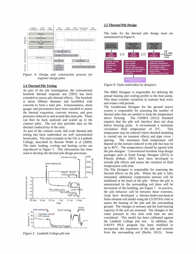
Figure 4: Design and construction process for
engineer design piles
2.4 Thermal Pile Testing
As part of the site investigation, the conventional
borehole thermal response test (TRT) has been
extended to assess pile thermal effects. The borehole
is about 300mm diameter and backfilled with
concrete to form a mini pile. Extensometers, strain
gauges and piezometers have been installed to assess
the thermal expansion, concrete stresses, and pore
pressures induced in and around this mini pile. These
can then be back analysed and scaled up to the
contract piles. The test also provides data on the
thermal conductivity of the soils.
As part of the contract work, full scale thermal pile
testing has been undertaken on well instrumented
bored piles. The main example in the UK is Lambeth
College, described by Bourne Webb et al (2009).
The static loading, cooling and heating cycles are
reproduced in Figure 5. This information has been
used to develop the thermal pile design processes.
Figure 5: Lambeth College pile test
2.5 Thermal Pile Design
The tasks for the thermal pile design team are
summarized in Figure 6.
Figure 6: Tasks undertaken by designers
The M&E Designer is responsible for defining the
annual heating and cooling profile to the heat pump.
This must consider variations in summer heat wave
and winter cold periods.
The Geothermal Designer for the ground source
system is responsible for assessing the number of
thermal piles that are needed to keep the temperature
above freezing. The GSHPA (2012) Standard
requires that the pile soil interface does not drop
below freezing point. It recommends a minimum
circulation fluid temperature of 2°C. This
temperature may be reduced where detailed modeling
is carried out on transient effects and pipe cover /
spacing. The maximum fluid temperature will
depend on the stresses induced in the pile but may be
up to 40°C. The temperatures should be agreed with
the pile designer. Conventional borehole loop design
packages such as Earth Energy Designer (2012) or
Pilesim (Pahud, 2007) have been developed to
include pile effects and assess the variation of fluid
temperatures with time.
The Pile Designer is responsible for assessing the
thermal effects on the pile. Where the pile is fully
restrained, additional compression stresses will be
mobilized at the head of the pile. Where the pile is
unrestrained by the surrounding soil there will be
movement of the building, see Figure 7. In practice,
the pile behavior will be between these extremes.
Arup have developed a thermo-hydro-mechanical
finite element soil model using the LS DYNA code to
assess the heating of the pile and the surrounding
ground. The changes in stresses and the load bearing
capacity of the soil are assessed. The changes to the
water pressure in clay soils with time are also
considered. This model has been calibrated against
the Lambeth College pile test. In addition, the
OASYS PILE program has been modified to
incorporate the expansion of the pile and restraint
from the surrounding soil (Bailie, 2012). Some

results for the end of cooling and heating stages of
the Lambeth College pile test are shown in Figure 8.
This work has been undertaken with Cambridge
University.
Figure 7: Restrained and unrestrained pile model
Figure 8: Lambeth College back analysis – Measured
and predicted pile axial loads
The seasonal expansion and contraction of the
thermal pile has also been considered, see Figure 9.
This is compared with the vertical cyclic loading of
piles and the effect on factor of safety, Poulos (1989).
The accumulative pile head settlement has also been
considered based on Matlock and Foo (1980).
Details are given in GSHPA (2012).
Figure 9: Seasonal cyclic expansion of pile leads to
increased movements
2.6 City Scale
On a city scale, the existing London underground
system has experienced a long term increase in the
temperature within tunnels and in the surrounding
ground, Botelle et al (2010). The Crossrail project
has introduced thermal piles and walls systems into
the station boxes. These will be available for heating
the overlying site developments above the stations
and will help to cool the ground and the adjacent
underground.
In the UK at present, only open GSHP systems,
which use advection, are regulated to achieve a
balanced annual heating and cooling load. The
schemes must be approved by the Environmental
Agency to ensure that existing abstractors are not
affected. Closed systems rely on conduction and are
not regulated.
3 THERMAL TUNNEL LININGS
This section discusses the background to the
development of thermal tunnels using thermal energy
segments (TES) in the UK. Additional background
information is given in the paper by Franzius and
Pralle (2011).
3.1 Concept
The concept for the thermal tunnels is shown in
Figures 10 and 11. The TES use plastic pipes
embedded within either the steel cage or fibre
reinforced segments. The plastic pile is PEXa grade
to enable tight bed radii to be formed and ensure 100
year durability at 15 bar pressures. The pipes also
enable permanent mechanical connections to be
formed in the segment box-outs, see Figure 11. The
box-out also allows for the pipe extension /
compression if joint rotation occurs.
Figure 10: The thermal tunnel concept

Figure 11: Thermal energy segments and box-out
connections
The ring to ring connections have to allow for the
segment rotation to allow the tunnel to be steered.
This flexibility is provided by using plastic pipes
mounted on the segment surface. Intermittent access
needs to provide for the header pipe connection, see
Figure 11.
The header pipe connections occur at about every
fifth segment ring. A reverse return system is used to
balance the head loss around all the ring circuits, see
Figure 12. The header pipes transfer the flow back to
the surface connection points at between 250m and
400m centres. Larger spacing of connection points
should be avoided to control hydraulic head losses.
The surface connection points can be provided at
shafts, ends of the stations, cross passages or possibly
from adjacent boreholes, see Figure 10. Where
possible, a plant room is provided at ground level to
incorporate circulation pumps and de-airing systems.
Heat exchangers can be provided if the tunnel system
is to be hydraulically separate from the building
circulation system.
Figure 12: Header piles with reverse return and
surface connections
3.2 Design Considerations
The efficiency of the thermal tunnel is influenced by
the air temperature inside the tunnel as well as the
surrounding ground temperature. Short-run tunnel air
temperatures are often controlled by the surface air
temperature and are called “cold” tunnels, see Figure
13. Longer metro and cable tunnels develop high
internal air temperatures and are called “hot” tunnels,
see Figure 13. For example, the motors in a London
Crossrail trains will emit about 1MW of heat and one
train passes at 2.5 minute intervals during peak times.
Air conditioning adds an extra 0.1MW. At peak
times this is about 22W/m2 and on a weekly average
this is 13W/m2. Braking adds to the heat generation.
The ground permeability and hydraulic gradient can
also affect the thermal tunnel efficiency.
Figure 13: Cold and hot tunnels
The thermal tunnel design is based on modeling the
heat transfer from the tunnel air and the surrounding
ground to the water filled pipes in the segments. The
LS DYNA numerical model used to assess this
transfer is shown in Figure 14. The model has been
calibrated against periods with TES heat extraction
rates of zero, 10W/m2 and 30W/m2 and the effects of
the circulation water are modeled, see Figure 15. The
model includes the heat load from the trains and the
temperatures in the surrounding ground.
Figure 14: TES model showing heat flow from tunnel
to pipes and soil

Figure 15: Temperature variation in the pipe – for
zero, 10 and 30w/m2 continuous
extraction rates
The stress in the concrete segments and the
surrounding ground was also studied in LS DYNA
using a Thermo-Hydro-Mechanical (THM) soil
model, see Figure 16. Some results are shown in
Figure 17. These results highlighted that the hoops
stress increased by about 7% due the heating and
expanding the lining and the ground. compared with
the „no heating‟ case. The circulating water also
induced thermal gradients and stresses across the
segments. This lead to a further 2% increase in hoop
stress. Local tensile stresses were induced next to the
pipes due to the cooling effects.
Figure 16: FE model used for stress analysis of
tunnel segments with pipes and
surrounding soil
Figure 17: Comparison of maximum principal stress
distribution in segments during summer
A tunnel heating and ventilation program was used to
calculate the combined effect of trains running
through the tunnels. It included allowances for heat
given off at station stops, braking heat during entry to
the stations and acceleration heat when exiting
stations, see Figure 18. The heat extraction from the
TES was also included and some results are shown in
Figure 19. These show that in summer the tunnel air
temperature is reduced by about 5°C with the flow
and return water circulation water temperatures of 21
and 26°C in central London. This leads to a heat
transfer of about 10W/m². These water circulation
temperatures are high enough to be used with a heat
pump for domestic hot water.
Figure 18: Tunnel ventilation model extended to
include TES heat extraction
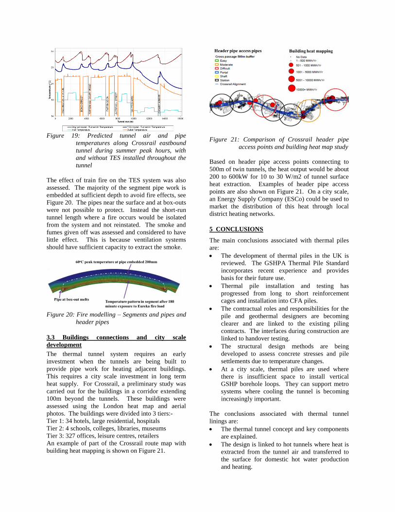
Figure 19: Predicted tunnel air and pipe
temperatures along Crossrail eastbound
tunnel during summer peak hours, with
and without TES installed throughout the
tunnel
The effect of train fire on the TES system was also
assessed. The majority of the segment pipe work is
embedded at sufficient depth to avoid fire effects, see
Figure 20. The pipes near the surface and at box-outs
were not possible to protect. Instead the short-run
tunnel length where a fire occurs would be isolated
from the system and not reinstated. The smoke and
fumes given off was assessed and considered to have
little effect. This is because ventilation systems
should have sufficient capacity to extract the smoke.
Figure 20: Fire modelling – Segments and pipes and
header pipes
3.3 Buildings connections and city scale
development
The thermal tunnel system requires an early
investment when the tunnels are being built to
provide pipe work for heating adjacent buildings.
This requires a city scale investment in long term
heat supply. For Crossrail, a preliminary study was
carried out for the buildings in a corridor extending
100m beyond the tunnels. These buildings were
assessed using the London heat map and aerial
photos. The buildings were divided into 3 tiers:-
Tier 1: 34 hotels, large residential, hospitals
Tier 2: 4 schools, colleges, libraries, museums
Tier 3: 327 offices, leisure centres, retailers
An example of part of the Crossrail route map with
building heat mapping is shown on Figure 21.
Figure 21: Comparison of Crossrail header pipe
access points and building heat map study
Based on header pipe access points connecting to
500m of twin tunnels, the heat output would be about
200 to 600kW for 10 to 30 W/m2 of tunnel surface
heat extraction. Examples of header pipe access
points are also shown on Figure 21. On a city scale,
an Energy Supply Company (ESCo) could be used to
market the distribution of this heat through local
district heating networks.
5 CONCLUSIONS
The main conclusions associated with thermal piles
are:
The development of thermal piles in the UK is
reviewed. The GSHPA Thermal Pile Standard
incorporates recent experience and provides
basis for their future use.
Thermal pile installation and testing has
progressed from long to short reinforcement
cages and installation into CFA piles.
The contractual roles and responsibilities for the
pile and geothermal designers are becoming
clearer and are linked to the existing piling
contracts. The interfaces during construction are
linked to handover testing.
The structural design methods are being
developed to assess concrete stresses and pile
settlements due to temperature changes.
At a city scale, thermal piles are used where
there is insufficient space to install vertical
GSHP borehole loops. They can support metro
systems where cooling the tunnel is becoming
increasingly important.
The conclusions associated with thermal tunnel
linings are:
The thermal tunnel concept and key components
are explained.
The design is linked to hot tunnels where heat is
extracted from the tunnel air and transferred to
the surface for domestic hot water production
and heating.

The DYNA modeling of the tunnel heat transfer
and segment concrete stresses is explained. In
addition the conventional tunnel heating and
ventilation system model is extended to include
the heat extracted by the circulating fluid. The
impact on cooling the tube is considered.
Fire protection is discussed but found not to be
appropriate for the surface pipe work.
At a city scale, investment is needed in the
tunnel pipe work. Early studies are required to
assess the way the buildings use tunnel heat and
to make the business case.
ACKNOWLEDGEMENTS
The work by the GSHPA thermal pile subcommittee
is acknowledged in the standard development. The
research work carried out by Cambridge and
Southampton universities has provided a framework
for instrumentation, monitoring and design.
The thermal tunnel work required a multi discipline
approach from within Arup / Atkins Crossrail team.
The continuing support to the project by Crossrail is
recognized, together with Mott MacDonald‟s input
on the H&V modeling and Rehau‟s work on the
pipework design.
REFERENCES
Amis T, Bourne-Web P, Amatya B. (2009),
“Geothermal Business Bouyant”, Geodrilling
International, 24 March.
Bailie P. (2012), “Sustainable Demands”, Ground
Engineer, 22 September.
Botelle, M., Payne, K., Redhead, B. (2010),
“Squeezing the heat out of London's Tube”,
Proceedings of the ICE - Civil Engineering,
163, (3), 114 –122.
Bourne-Webb P, Amatya, B, Soga, K, Amis, T,
Davidson, C, and Payne, P. (2009), “Energy pile
test at Lambeth College, London: geotechnical
and thermodynamic aspects of pile response to
heat cycles”, Geotechnique, 59 (3), 237–248.
Brandl, H. (2006), “Energy foundations and other
thermo-active ground structures”, Geotechnique,
56 (2), 81–122
Earth Energy Designer. (2012),
http://www.buildingphysics.com/index.htm.
Franzius, J. N. and Pralle, N. (2011), “Turning
segmental tunnels into sources of renewable
energy.” Proceeding of ICE, Civil Engineering,
164, 35-40.
GSHPA, (2012), “Thermal Pile Design, Installation
and Materials Standards”, Ground Source Heat
Pump Association,
http://www.gshp.org.uk/GSHPA_Thermal_Pile_
Standard.html
Institution of Civil Engineers, (2007), “The
Specification for Piling and Embedded Retaining
Walls, 2nd edition”.
Matlock, H., and Foo, S.H.C. (1908), “Axial analysis
of piles using a hysteretic and degrading soil
model”, Proceedings of Conference Numerical
methods in offshore piling, ICE, London, 127-
133.
NHBC Foundations. (2010), “Efficient design of
piled foundations for low rise housing design
guide”, NF21 ISBN 978-1-84806106-4.
Ove Arup & Partners Ltd. (2005), “DTI Partners in
Innovation. Ground Storage of Building Energy
Overview Report”, May, PII Ref: O-02-ARUP3.
Pahud D. (2007), “PILESIM2: Simulation Tool for
Heating and Cooling Systems with Energy Piles
or Multiple Borehole Heat Exchangers”. User
Manual, ISAAC –DACD – SUPSI, Switzerland.
Poulos, H G. (1989), “The Mechanics of Calcareous
Sediments”, John Jaeger Memorial Lecture,
Australian Geomechanics, Special Edition. 8-41.
Suckling, T. (2004), “Geothermal Piles used at Keble
College, Oxford”, The Structural Engineer, 19.
![Pile Foundation Design[1] - ITDmtp.itd.co.th/ITD-CP/data/PileFoundationDesign.pdf · Introduction to pile foundations Pile foundation design Load on piles Single pile design Pile](https://img.dokumen.tips/doc/110x75/5a6ffb387f8b9ab1538b8376/pile-foundation-design1-itdmtpitdcothitd-cpdatapilefoundationdesignpdfpdf.jpg)


![[04899] - Design of Pile & Pile-Cap](https://img.dokumen.tips/doc/110x75/5695d3331a28ab9b029d273d/04899-design-of-pile-pile-cap.jpg)