Embed Size (px)
Citation preview

DEVELOPMENT ON PRE-HEATING SYSTEM FOR AUTOTHERMAL REFORMER FOR FUEL CELL APPLICATION
FAZRUL AMAR BIN ISHAK
A thesis submitted in fulfillment of the Requirement for the award of the degree of
Bachelor of Engineering (Gas Technology)
Faculty of Chemical and Natural Resources Engineering Universiti Malaysia Pahang (UMP)
MAY 2008

ii
I declared that this thesis entitled ‘Development of Preheating System for Autothermal
Reformer for Fuel Cell Application’ is the result of my own research except as cited in
the references. The thesis has not been accepted for any degree is not concurrently
submitted candidature of any degree.
Signature :
Name of Candidates : Fazrul Amar bin Ishak
Date : 16 May 2008

iii
Special dedicated to my beloved mother and father

iv
ACKNOWLEDGEMENT
I am deeply grateful to my thesis supervisor Pn Rosmawati bt Naim for his
continuous guidance, support and enthusiasm throughout this work, and being an
inspiring teacher for me.
I would like to express my most sincere thanks to Mr. Mohd Masri b A.Razak
for co-supervising my work and invaluable suggestion and advice.
I am also would like to thank to all my friends for their assistance in giving
opinion during the course of my study.
Finally, I would express my gratitude to my mother, father and to all my siblings
for their endless love and support

v
ABSTRACT
The objective of this research is to investigate the performance of catalytic combustion
of hydrogen by using Pt/Al2O3 in different weight loading catalyst ranged from 0.06 to
0.2 gram in assisting the catalytic combustion of methane experimentally. 1 wt% and 3
wt% platinum catalyst used to determine the performance of catalytic combustion of
hydrogen. The platinum supported with alumina to increase the area of platinum to
faster the reaction and to reduce cost. The behavior of hydrogen has been studied
accordingly based on their auto ignition in room temperature and atmospheric pressure
when contact with platinum with air in the range of lower and upper flammability limits.
Sets of range from 72% to 97% fuel to air ratio were used for the experiment. Different
weight loading of catalyst and catalyst weight percent of Pt in alumina gave various
performances and the effect of air/fuel ratio was observed as well to get the best result.
The catalytic combustion of hydrogen was a complete combustion and could reach up to
450°C. The experiment held in vertical single bed reactor whereby the exit temperature
of catalytic combustion of hydrogen was recorded for performance comparison. The
best performance was hydrogen flow rate set to 772.8 ccm and air set to 272.16 ccm
with 1wt% Pt and weight loading 0.1gram which gave temperature of 459°C because the
effect of larger surface reaction.

vi
ABSTRAK
Objektif kepada penyelidikan ini adalah untuk menyiasat perlaksanaan pembakaran
bermangkin hidrogen dengan menggunakan Pt/Al2O3 dalam kandungan pemangkin yang
berbeza 0.06 gram sehingga 0.2 gram dalam membantu pembakaran bermangkin metana
secara eksperimen. 1 wt% and 3 wt% katalis platinum digunakan untuk dalam
pembakaran bermangkin hidrogen. Platinum disokong oleh alumina untuk
meningkatkan luas permukaan platinum bagi mempercepatkan tindak balas dan
mengurangkan kos. Tindakbalas hidrogen telah diselidik secara meluas bahawa terbakar
secara automatik pada suhu bilik dan tekanan atmosfera apabila bersentuh dengan
platinum dengan kehadiran udara pada had atas dan bawah keterbakaran. Pada had 72%
sehingga 97% nisbah bahan bakar kepada udara digunakan dalam eksperimen ini.
Berbeza kandungan berat katalis dan berbeza peratus katalis platinum akan memberikan
keputusan yang berbeza dan kesan perubahan nisbah bahan bakar kepada udara juga di
perhatikan untuk keputusan yang terbaik. Pembakaran bermangkin hidrogen adalah
lengkap dan boleh mencecah kepada suhu 450°C. Eksperimen dijalankan didalam
reactor kaca secara menegak dimana suhu yang terhasil direkodkan sebagai
perbandingan keputusan. Prestasi terbaik adalah pada kadar aliran hydrogen 772.8 ccm
dan udara 272.16 ccm dengan 1wt% Pt dan berat 0.1gram mencatatkan suhu 450°C
disebabkan kesan luas permukaan tindak balas yang lebih besar.
vii
TABLE OF CONTENTS
CHAPTER TITLE PAGE
ACKNOWLEDGMENT iv
ABSTRACT v
ABSTRAK vi
TABLE OF CONTENT vii
LIST OF ABBREVIATION x
LIST OF FIGURE xii
LIST OF TABLE xiv
1 INTRODUCTION 1
1.1 Background of study 1
1.2 Problem statement 3
1.3 Objectives of the project 3
1.4 Scope of research work 3
2 LITERATURE REVIEW 4
2.1 History of fuel cell 5
2.2 Type of fuel cell 5
2.2.1 Proton exchange membrane 5
2.2.2 Direct methanol fuel cell 6
2.2.3 Phosphoric acid fuel cell 8
2.2.4 Alkaline fuel cell 9
2.2.5 Solid oxide fuel cell 10
2.2.6 Molten carbonate fuel cell 11

viii
2.3 Production of hydrogen 13
2.3.1 Steam reforming 13
2.3.2 Partial oxidation 14
2.3.3 Auto thermal reforming 15
2.4 Hydrogen from natural gas 15
2.4.1 Methane 16
2.5 Catalytic combustion 17
2.5.1 Catalytic combustion of hydrogen 17
2.5.2 Catalytic combustion of methane 19
2.6 Flammability Limit 22
2.6.1 Flammability limit of hydrogen 22
2.7 Autoignition temperature 24
2.8 Chemistry for hydrogen autoignition 24
2.9 Detailed chemistry 26
2.10 Autoignition characteristics 28
2.11 Autoignition simplifications 31
2.12 Systematically reduced chemistry 33
3 METHODOLOGY 35
3.1 Material 35
3.1.1 Aluminium oxide 35
3.1.2 Hexacloroplatinic acid 36
3.1.3 Methane gas 36
3.1.4 Hydrogen gas 37
3.2 Catalyst preparation 38
3.3 Experimental rig for catalytic combustion 39
ix
4 RESULT AND DISCUSSION 41
4.1 Result 41
4.2 Temperature profile for catalytic 42
combustion of hydrogen for 3wt% Pt,
0.2g weight loading.
4.3 Temperature profile for catalytic 43
combustion of hydrogen for 3wt% Pt,
0.06g weight loading.
4.4 Temperature profile for catalytic 46
combustion of hydrogen for 1wt% Pt,
74% fuel/air ratio.
4.5 Discussion. 47
4.5.1 Effect of fuel/air ratio 48
4.5.2 Catalyst weight loading 48
4.5.3 Percent of platinum 49
4.5.4 Dispersion of catalyst 49
5 CONCLUSION AND RECOMMENDATION 51
5.1 Conclusion 51
5.2 Recommendation 52
REFERENCES 55
APPENDICES 59

x
LIST OF ABBREVIATIONS AFC - Alkaline fuel cell
Al2O3 - Alumina
ATR - Autothermal reformer
CCM - Centimeter cubit minute
CST - Catalytically stabilized combustion
CHP - Combined heat power
CH4 - Methane
C2H6 - Ethane
C3H8 - Propane
C4H10 - Butane
CO - Carbon monoxide
CO2 - Carbon dioxide
CPO - Catalytic partial oxidation
H2 - Hydrogen
H2O - Water
MCFC - Molten carbonate fuel cell
PAFC - Phosphoric acid fuel cell
Pd - Palladium
PEMFC - Proton exchange membrane fuel cell
POX - Partial oxidation
LPG - Liquefied petroleum gas
Pt - Platinum
Pt/Al2O3 - Platinum alumina
SPFC - Solid polymer fuel cell
SOFC - Solid oxide fuel cell

xi
UPS - Uninterrupted power supply
WGS - water gas shift

xii
LIST OF FIGURES
FIGURE NO. TITLE PAGE
1.1 Work principle of fuel cell. 2
2.1 William Grove gas battery. 4
2.2 Schematic view of PEM fuel cell. 6
2.3 Schematic view of methanol fuel cell. 7
2.4 Schematic view of PAFC fuel cell. 8
2.5 Schematic view of alkaline fuel cell. 9
2.6 Schematic view of SOFC fuel cell. 10
2.7 Schematic view of molten carbonate fuel 11
cell.
2.8 Conversion versus temperature in catalytic 21
combustion.
2.9 Variation of hydrogen flammability limits 24
with temperature.
2.10 The region of validity for hydrogen-air autoignition 32
2.11 Comparison of the predicted product of the 33
autoignition.
3.1 Methane structure. 36
3.2 Process flow diagram of the system. 39
3.3 Deposition of Pt/Al2O3. 40
4.1 Comparison in different fuel/air ratio, 0.2gram 43
catalyst loading and 3% Pt.
4.2 Comparison in different fuel/air ratio, 0.06gram 45
catalyst loading and 3% Pt.

xiii
4.3 Comparison in different catalyst loading, 43% 47
fuel/air ratio and 1% Pt.

xiv
LIST OF TABLES
TABLE NO. TITLE PAGE
2.1 Summary for different type of fuel cell. 12
2.2 The detailed mechanism and associated rate 26
parameters.
3.1 Properties of Al2O3. 36
3.2 Properties of methane. 37
3.3 Properties of hydrogen. 38
4.1 Parameter setting for the experiment. 41
4.2 Result for Fuel to air ratio from 92% to 97% 42
4.3 Result for Fuel to air ratio range from 72% to 84% 44
4.4 Data for different catalyst weight loading. 46

CHAPTER 1
INTRODUCTION
1.1 Background of study
A fuel cell by definition is an electrical cell, which unlike storage cells can be
continuously fed with a fuel so that the electrical power output is sustained indefinitely
(Reed, 1995).
A fuel cell consists of two electrodes sandwiched around an electrolyte. Oxygen
passes over one electrode and hydrogen over the other, generating electricity, water and
heat. Hydrogen fuel is fed into the anode of the fuel cell. Oxygen enters the fuel cell
through the cathode. Encouraged by catalyst, the hydrogen atom splits into a proton and
an electron, which take different paths to the cathode. The proton passes through the
electrolyte. The electrons create a separate current that can be utilized before they return
to the cathode, to be reunited with the hydrogen and oxygen in a molecule of water.

2
Figure 1.1: Working principle of fuel cell
In general, fuel cells are classified according to the electrolyte use. There are the
alkaline fuel cell used in space vehicle power system, the phosphoric acid fuel cell
(PAFC) used in both road transportation and stationary engines, the solid polymer fuel
cell (SPFC) also used in both road transportations and stationary engines, the molten
carbonate fuel cell (MCFC) used in stationary engines and the solid oxide fuel cell
(SOFC) used only in stationary engines (Chen and Elnashaie, 2004).
A fuel cell system which includes a fuel reformer can utilize the hydrogen from
any hydrogen fuel – from natural gas to methanol, and even gasoline.
The three major approaches for the conversion of hydrocarbon fuels to hydrogen
are steam reforming, partial oxidation and auto thermal reforming. The last mention is a
chemical combination of steam reforming and partial oxidation. Argonne National
Laboratory has articulated the advantages of the auto thermal reforming (ATR) process
for many applications that face constraint on size, duty cycle such as in automotive
power plant. In the ATR process, fuel is co-fed with steam and air, and the feed
composition is adjusted to maintain a slightly exothermic reaction.
In general, fuel cell can be used for a wide variety of applications, the most
important of which are as power source for vehicle, as a stationary power source and as
power sources for portable devices. Natural gas and propane are attractive for stationary

3
applications since they are low-cost fuels and the infrastructure for their transportation
already exists (Wang et al., 2005).
1.2 Problem statement
Conventional autothermal reformer have disadvantage, particularly with respect to
fuel cell-related applications. Conventional autothermal reformer and associated heat
recovery equipment tend to be quite large, which impacts material cost and overall
manufactured cost. This is especially disadvantageous in vehicular application, where
space is also at a premium.(Faye et.al,2004).
1.3 Objective of the project
a) Assemble and fabricate test rig on preheating system using catalytic combustion
for ATR.
b) Study on performance testing by using platinum alumina (Pt/Al2O3) as catalyst
and hydrogen as fuel in preheating process.
1.4 Scope of research
Scope of this research is to fabricate the rig for pre-heating system at
Autothermal reformer and make performance test by different weight loading catalyst of
1% and 3% Pt in alumina and different fuel to air ratio range 15% to 75% to achieve
minimum temperature of catalytic combustion of hydrogen above 368°C


CHAPTER 2
LITERATURE REVIEW 2.1 History of fuel cell
The history of fuel was discovered by William Grove in early 1839 by reversing
water electrolysis to generate electricity from hydrogen and oxygen. A fuel cell does not
need recharging, it operates quietly and efficiently, and when hydrogen is used as fuel, it
generates only power and drinking water. Thus it is a called zero emission engine.
Grove’s fuel cell was a fragile apparatus filled with dilute sulfuric acid into which
platinum electrodes were dipped.
Figure 2.1: William Grove's 'gas battery', the first fuel cell.

5
2.2 Type of fuel cell
Fuel cells are a family of technologies. Fuel cell types are characterized by their
electrolytes and temperature of operation. (Gregor, 2003).
2.2.1 Proton exchange membrane
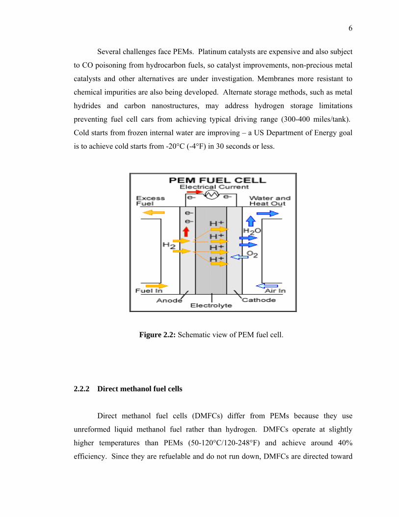
Proton exchange membrane (PEM) fuel cells have a solid polymer membrane as
an electrolyte. Due to membrane limitations, PEMs usually operate at low temperatures
(60-100°C/140-212°F), but new developments have produced higher temperature PEMs
(up to 200°C/392°F). Since platinum is the most chemically active substance for low
temperature hydrogen separation, it is used as the catalyst. Hydrogen fuel is supplied as
hydrogen gas or is reformed from methanol, ethanol, natural gas or liquefied petroleum
gas and then fed into the fuel cell. The power range of existing PEMs is about 50W to
150kW. The advantages of using PEM fuel cells include:
a) Low weight and volume with good power-to-weight ratio,
b) Low temperature operation, so less thermal wear to components, and
c) Quick starts, with full power available in minutes or less.
These advantages make PEMs well-suited to automotive and specialty vehicle
applications such as scooters and forklifts. Many on-road trials are providing
information to make PEMs competitive with internal combustion engines. Quick-
starting PEMs can also provide back-up power to telecommunications and other sites
requiring uninterrupted power supplies (UPS). PEMs additionally offer efficient
operation – up to 50% electrical efficiency for the fuel cell itself and over 85% total
efficiency when waste heat is captured for small-scale space and water heating
(combined heat and power, or CHP). Hundreds of CHP and UPS PEM units have been
deployed in demonstrations, and a number of units are now available for sale.
6
Several challenges face PEMs. Platinum catalysts are expensive and also subject
to CO poisoning from hydrocarbon fuels, so catalyst improvements, non-precious metal
catalysts and other alternatives are under investigation. Membranes more resistant to
chemical impurities are also being developed. Alternate storage methods, such as metal
hydrides and carbon nanostructures, may address hydrogen storage limitations
preventing fuel cell cars from achieving typical driving range (300-400 miles/tank).
Cold starts from frozen internal water are improving – a US Department of Energy goal
is to achieve cold starts from -20°C (-4°F) in 30 seconds or less.
Figure 2.2: Schematic view of PEM fuel cell.
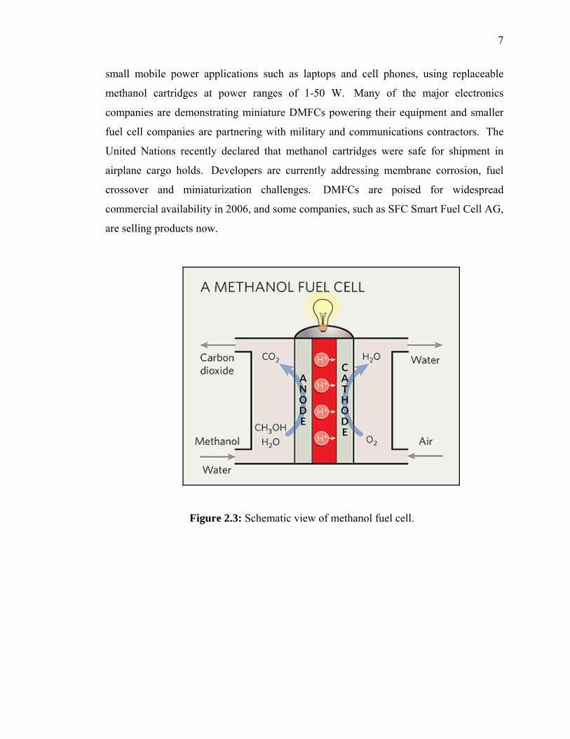
2.2.2 Direct methanol fuel cells
Direct methanol fuel cells (DMFCs) differ from PEMs because they use
unreformed liquid methanol fuel rather than hydrogen. DMFCs operate at slightly
higher temperatures than PEMs (50-120°C/120-248°F) and achieve around 40%
efficiency. Since they are refuelable and do not run down, DMFCs are directed toward
7
small mobile power applications such as laptops and cell phones, using replaceable
methanol cartridges at power ranges of 1-50 W. Many of the major electronics
companies are demonstrating miniature DMFCs powering their equipment and smaller
fuel cell companies are partnering with military and communications contractors. The
United Nations recently declared that methanol cartridges were safe for shipment in
airplane cargo holds. Developers are currently addressing membrane corrosion, fuel
crossover and miniaturization challenges. DMFCs are poised for widespread
commercial availability in 2006, and some companies, such as SFC Smart Fuel Cell AG,
are selling products now.
Figure 2.3: Schematic view of methanol fuel cell.

8
2.2.3 Phosphoric acid fuel cell
The phosphoric acid fuel cell (PAFC) is the fuel cell technology, with the
greatest experience in consumer applications. UTC Fuel Cells (formerly ONSI and
International Fuel Cells) paved the way for the technology, selling systems since the
early 1990’s and recently reaching the milestone of more than one billion kilowatt-hours
of energy with its PureCell™ 200 power plant solution. PAFCs use liquid phosphoric
acid as an electrolyte with a platinum catalyst. Anode and cathode reactions are similar
to PEMs, but operating temperatures are slightly higher (150-200°C/302-392°F) making
them more tolerant to reforming impurities. PAFCs use hydrocarbon sources such as
natural gas, propane or waste methane. PAFCs are typically used for medium to large-
scale stationary power generation, attaining a 36-42% electrical efficiency and an
overall 85% total efficiency with co-generation of electricity and heat. The power range
of existing PAFCs is 25-250 kW. However, if several units are linked, PAFCs can
achieve a combined power output greater than 1 MW (an 11 MW PAFC power plant is
operating in Japan).
Figure 2.4: Schematic view of PAFC fuel cell.
9
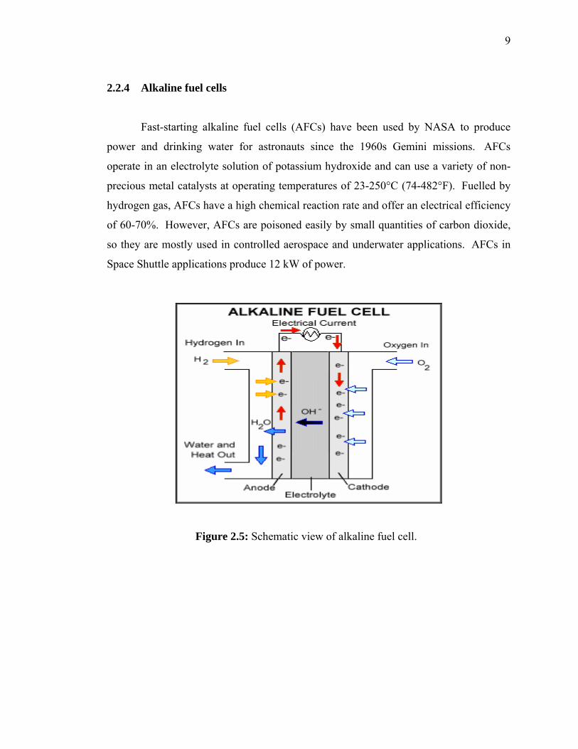
2.2.4 Alkaline fuel cells
Fast-starting alkaline fuel cells (AFCs) have been used by NASA to produce
power and drinking water for astronauts since the 1960s Gemini missions. AFCs
operate in an electrolyte solution of potassium hydroxide and can use a variety of non-
precious metal catalysts at operating temperatures of 23-250°C (74-482°F). Fuelled by
hydrogen gas, AFCs have a high chemical reaction rate and offer an electrical efficiency
of 60-70%. However, AFCs are poisoned easily by small quantities of carbon dioxide,
so they are mostly used in controlled aerospace and underwater applications. AFCs in
Space Shuttle applications produce 12 kW of power.
Figure 2.5: Schematic view of alkaline fuel cell.

10
2.2.5 Solid oxide fuel cells
Solid oxide fuel cells (SOFCs) are one of the high temperature fuel cells,
operating at 800-1000 °C (1472-1832°F) High temperature operation eliminates the
need for precious metal catalysts and can reduce cost by recycling the waste heat from
internal steam reformation of hydrocarbon fuels. SOFCs are tolerant to CO poisoning,
allowing CO derived from coal gas to also be employed as source of fuel. These fuel
cells use a solid ceramic electrolyte and produce a power output of 2-100 kW and can
attain 220 kW-300 kW when used in a SOFC/gas turbine hybrid system. Demonstrated
electrical efficiencies are 45-55%, with total efficiencies of 80-85% with cogeneration
of waste heat. SOFCs are well-suited for medium-to-large scale, on-site power
generation or CHP (hospitals, hotels, universities), and are also being marketed for
telecommunications back up and as auxiliary power units (APUs) for military vehicle
on-board equipment.
Figure 2.6: Schematic view of SOFC fuel cell.

11
2.2.6 Molten carbonate fuel cells
Molten carbonate fuel cells (MCFCs) operate at 600-750°C (1112-1382°F) and
use a molten alkali carbonate mixture for an electrolyte. MCFCs typically range
between 75-250 kW, but when using combined units, have produced up to 5 MW of
power. Electrical efficiencies are 50-60%, with total efficiencies of 80-85% with
cogeneration of waste heat. To date, MCFCs have operated on hydrogen, carbon
monoxide, natural gas, propane, landfill gas, marine diesel, and simulated coal
gasification products.
The challenges to both SOFC and MCFC development include slow start up,
strong thermal shielding requirements, and difficulty in developing durable materials for
the high temperature operating environment. Developers and the US government (Solid
State Energy Conversion Alliance) are also working on lower cost, greater durability,
low-temperature SOFCs (about 800°C), as well as more powerful SOFC/gas turbine
hybrids (1 MW or greater). Current MCFC research focuses on reduction of size and
cost, as well as possible integration with gas turbines to increase performance.
Figure 2.7: Schematic view of molten carbonate fuel cell.

12
Table 2.1: Summary for different type of fuel cell (Appleby and Foulkes, 2004).
PEFC AFC PAFC MCFC SOFC
Electrolyte
Hydrated Polymeric
Ion Exchange Membrane
Mobilized or
Immobilized Potassium Hydroxide in asbestos
matrix
Immobilized Liquid
Phosphoric Acid in SiC
Immobilized Liquid Molten
Carbonate in LiALO2
Perovskites(ceramics)
Electrodes Carbon Transition metal Carbon
Nickel and Nickel Oxide
Perovskite and Metal Cement
Catalyst Platinum Platinum Platinum Electrode material
Electrode material
Interconnect Carbon or metal Metal Graphite
Stainless steel or Nickel
Nickel, ceramic or
steel Operating
Temperature (°C)
40-80 65-220 205 650 600-1000
External Reformer
For Hydrocarbon
Fuels
Yes Yes Yes No, for some fuels
No, for some fuels
and cell design
External Reformer for Hydrocarbon
Fuels
Yes, plus purification to remove trace CO
Yes, plus purification to remove
CO and CO2
Yes No No
Prime Cell Components
Carbon-based
Carbon-based
Graphite-based
Stainless-based Ceramic
Product Heat Management
Process Gas + Liquid Cooling Medium
Process Gas +
Electrolyte Circulation
Process Gas +Liquid Cooling
medium or steam
Internal Reforming + Process Gas
Internal Reforming + Process
gas

13
2.3 Production of hydrogen Fuel cells generally run on hydrogen, but any hydrogen-rich material can serve
as a possible fuel source. This includes fossil fuels – methanol, ethanol, natural gas,
petroleum distillates, liquid propane and gasified coal. The hydrogen is produced from
these materials by a process known as reforming. This is extremely useful where stored
hydrogen is not available but must be used for power, for example, on a fuel cell
powered vehicle.
There are three basic reformer designs are being evaluated for fuel cells for use
in vehicles: steam reforming, partial oxidation and auto-thermal reforming. Steam
reformers combine fuel with steam and heat to produce hydrogen.
The heat required to operate the system is obtained by burning fuel or excess
hydrogen from the outlet of the fuel cell stack. Partial oxidation reformers combine fuel
with oxygen to produce hydrogen and carbon monoxide. The carbon monoxide then
reacts with steam to produce more hydrogen. Partial oxidation releases heat, which is
captured and used elsewhere in the system. Auto-thermal reformers combine the fuel
with both steam and oxygen so that the reaction is in heat balance.
2.3.1 Steam reforming
Steam reforming of methane from natural gas is the standard way of producing
hydrogen on an industrial scale. It is therefore of general importance to a hydrogen
economy. In addition, smaller scale methane steam reformer have been developed to
provide hydrogen for stationary power systems based on low-temperature fuel cell,
Proton Exchange Membrane Fuel Cell (PEMFC) and Phosphoric Acid Fuel Cell
(PAFC).

14
The methane steam reforming is described by:
CH4 + H2O CO + 3H2 ∆H = 206kjmol-1 [2.1] Methane steam reforming is usually catalyzed by nickel (Ridler and Twigg, 1996) at
temperature between 750-1000°C, with excess steam to prevent carbon deposition on
the nickel catalyst (Trimm and Onsan, 2001).
2.3.2 Partial oxidation
The second important reaction for generating hydrogen on an industrial scale is
partial oxidation (POX). It is generally employed with heavier hydrocarbons (Dams,
1996) or when special preferences exist because certain reactants (for example, pure
oxygen) are available within a plant. It can be seen as oxidation with less than the
stoichiometric amount of oxygen for full oxidation to the stable end products, carbon
dioxide and water.
For example, for methane: CH4 + 1/2O2 → CO + 2H2 ΔH = –36 kJmol–1 [2.2] and/or CH4 + O2 → CO2 + 2H2 ΔH = –319 kJmol–1 [2.3]

15
2.3.3 Auto thermal reforming Autothermal reforming (ATR) is a process in which both steam and air are
introduce to be the fuel. Compared to steam reforming, less water needed for
Autothermal reforming. In addition, the heat of steam reforming is provided by the
partial oxidation of fuel. Thus, no complex heat management needed, and system design
became a little simple.
Steam and auto thermal reforming reaction of LPG (propane/butane) over highs
surface area Ce2O (Ce2O2 (HAS)) under solid oxide fuel (SOFC) operating condition
was studied. The major consideration in the auto thermal reforming operation is the inlet
O2/LPG molar ratio, as the presence of too high an oxygen concentration could oxidize
hydrogen and carbon monoxide, produced from the steam reforming, to steam and
carbon dioxide. A suitable O/C molar ratio for auto thermal reforming on CeO2 (HAS)
been observed to be 0.6. (Laosiripojana et al. 2005).
2.4 Hydrogen from natural gas
Natural gas is a gaseous fossil fuel consisting primarily of methane but including
significant quantities of ethane, butane, propane, carbon dioxide, nitrogen, helium and
hydrogen sulphide. It is found in oil fields and natural gas fields and in coal beds (as
coal bed methane). When methane-rich gases are produced by the anaerobic decay of
non-fossil organic material, these are referred to as biogas. Sources of biogas include
swamps, marshes, and landfills (see landfill gas), as well as sewage sludge and manure
by way of anaerobic digesters, in addition to enteric fermentation particularly in cattle.
Natural gas is often informally referred to as simply gas, especially when compared to
other energy sources such as electricity. Before natural gas can be used as a fuel, it must
undergo extensive processing to remove almost all materials other than methane. The
by-products of that processing include ethane, propane, butanes, pentanes and higher
molecular weight hydrocarbons, elemental sulphur, and sometimes helium and nitrogen.

16
The primary component of natural gas is methane (CH4), the shortest and lightest
hydrocarbon molecule. It also contains heavier gaseous hydrocarbons such as ethane
(C2H6), propane (C3H8) and butane (C4H10), as well as other sulfur containing gases, in
varying amounts, see also natural gas condensate. Natural gas also contains and is the
primary market source of helium
2.4.1 Methane
Recent research concerning Catalytic Partial Oxidation (CPO) process has been
focused on methane, as it is today the major feedstock for the production of hydrogen by
steam reforming process on Ni catalysts Methane has the highest H/C ratio and thus is
the most obvious source for hydrogen. Literature data indicate that in CPO of methane,
Ni-based systems give high syngas yields but require operation at low temperatures to
reduce metal loss, while Pt shows very stable performance but lower H2 selectivity
(Dissanayake, 1991).
The partial oxidation of methane is based on the following exothermic reaction: CH4 + 1/2O2 → CO + 2H2, ∆H=−35.6kJ/mol. [2.4]
However, CH4 and O2 at high temperatures are involved in many reactions
giving principally CO, CO2, H2 and H2O as products, and the composition of the final
mixture depends on temperature, pressure, input gas composition and kinetics.

17
2.5 Catalytic combustion 2.5.1 Catalytic combustion of hydrogen
Catalytic combustion for hydrogen enables hydrogen combust easily at a
relatively low temperature whereat does not reach flame combustion. For the purpose of
eliminating this difficulty and in due consideration of the fact that hydrogen is more
readily combustible than any other fuel, attempts have been made to develop a catalyst
which enable combustion of hydrogen to proceed safely at low temperatures. (Haruta et
al 1981).
Catalytically stabilized combustion (CST) provides the best available low-NOx
combustion technology, with demonstrated NOx emissions less than 3 ppm (Beebe,
2000). In CST partial fuel conversion is attained catalytically (heterogeneously) and the
remaining fuel is combusted in a follow-up homogeneous (gas phase) combustion zone.
The heterogeneous combustion is a flameless process and does not contribute to NOx,
which is formed only via the homogeneous reaction pathway. CST is, therefore, a NOx-
preventing technology, resulting in a significant cost reduction compared to NOx-after
treatment techniques (SCR or SCONOX). The CST research activities are
internationally intensified, driven by the stringent NOx emission regulations in Europe
and the United States (non-attainment areas in the United States already impose a 3 ppm
NOx limit). CST has been recently commercialized in small-scale (1.5 MW) gas turbines
in the United States and current efforts focus on large-scale machines.
Further advancement in CST technology requires the development of catalysts
with improved activity (desired light-off temperature less than 450°C) and thermal
stability, understanding of the catalytic surface processes, knowledge of low-
temperature homogeneous kinetics and their respective coupling with heterogeneous
kinetics. The catalytic reactor in power generation systems consists of a multitude of
large surface-to-volume ratio catalytically coated channels, necessitating

18
multidimensional numerical models with capabilities of detailed hetero/homogeneous
chemistry, transport, and flow description. These models could be used to predict issues
of practical interest, such as light-off characteristics, the likelihood of homogeneous
ignition, and the attained fuel conversion within the catalytic reactor.
Heterogeneous kinetic studies of simple fuels such as H2, CO and CH4 over Pt or
Pd have progressed substantially over the last years, e.g., Hellsing et al. (1991),
Hickman and Schmidt (1993), Deutschmann (1996), and Aghalayam et al. (2000). In
addition, multidimensional numerical models capable of treating detailed surface and
gas-phase kinetics are now available (refer to Dogwiler (1998), Deutschmann and
Schmidt (1998)). The onset of homogeneous ignition within the catalytic reactor is
detrimental to the catalyst integrity (it can cause catalyst meltdown) and the knowledge
of such an event is of prime interest to CST reactor design. The gas-phase ignition is
strongly influenced by the hetero/homogeneous coupling (catalytic fuel depletion,
radical adsorption/desorption reactions) and, therefore, its accurate prediction requires
the use of validated hetero/homogeneous chemical reaction schemes. In Dogwiler
(1998) and Dogwiler et al. (1999), the authors validated hetero/homogeneous reaction
schemes in CST of CH4/air mixtures over Pt, using a 2-D elliptic fluid mechanical
model with elementary hetero/ homogeneous reaction schemes and experimental
ignition characteristics from an optically accessible catalytic combustor. Mantzaras and
Benz (1999) have provided analytical homogeneous ignition criteria in 2-D channel
configurations that included dependencies on the relevant chemical, flow, transport, and
geometrical parameters. Such criteria were further adapted to CH4/air CST in Mantzaras
et al. (2000) using the validated hetero/homogeneous schemes from Dogwiler (1998). Of
particular interest in natural gas-fueled turbines is the concept of hydrogen- assisted
CST. Addition of small amounts of H2 in natural gas reduces the catalyst light-off
temperature and improves the combustion stability by damping flame pulsations.
Dobbeling and Griffin (1999) proposed partial catalytic oxidation of a fraction of the
natural gas as a viable way of producing hydrogen in gas-turbine systems. The
knowledge of hydrogen CST is, therefore, an important step in the understanding of
hydrogen-assisted CST. In hydrogen-assisted CST, care has to be exercised to avoid

19
catalyst hot-spots and homogeneous ignition within the catalytic reactor: H2 is a strongly
diffusionally imbalanced fuel with a Lewis number Le Η 0.3, resulting in superadiabatic
surface temperatures (Pfefferle and Pfefferle, 1985), that could deactivate the catalyst
and promote homogeneous ignition.
2.5.2 Catalytic combustion of methane
The production of energy by the combustion of methane and natural gas is well
established. Overall, the reaction may be represented by the equation
CH4 + 2O2 → CO2 + 2H2O ∆H 298 = -802.7 kJ/mol
This overall equation is, however, a gross simplification with the actual reaction
mechanism involving very many free radical chain reactions. Gas-phase combustion can
only occur within given flammability limits, and the temperatures produced during
combustion can rise to above 1600 °C, where the direct combination of nitrogen and
oxygen to unwanted nitrogen oxides could occur.
Catalytic combustion offers an alternative means of producing energy. A wide
range of concentrations of hydrocarbon can be oxidized over a suitable catalyst, and it is
possible to work outside the flammability limits of fuel. Reaction conditions can usually
be controlled more precisely, with reaction temperatures being maintained below
1600°C. This may be important both to minimize the production of nitrogen oxides and
also to avoid thermal sintering of the catalyst. The catalytic combustion of methane is
somewhat more complicated, as a result the fact that it is necessary to initiate oxidation
at quite a high temperature. Once the reaction starts, subsequent oxidation is rapid and
the heat release is considerable. As a result, it is more difficult to control temperature
below the desired maximum.
With natural gas, it is somewhat easier to control temperature, since the presence
of overall amounts of higher hydrocarbons allows initiation of oxidation at lower

20
temperatures. Thus, for example, the light-off temperature of methane at an air: fuel
ratio of 5.3 is 368oC; for ethane, the corresponding value is 242oC. Once the higher
hydrocarbon starts to oxidize, the heat liberated is sufficient to heat up the system and to
initiate the oxidation of methane. Obviously, this depends on the fact that there is
sufficient higher hydrocarbon to supply the heat required. The main focus of this article
is on the chemistry of methane, but it is useful to remember that the use of natural gas
can introduce some change. The combustion of methane can produce carbon dioxide or
carbon monoxide, depending on the air: methane ratio:
CH4 + 2O2 → CO2 + 2H2O (1.1) CH4 + 3/2 O2 → CO + 2H2O (1.2) Other reactions may also be involved to a greater or less extent. These could include
steam reforming (1.3) and (1.4) and the water shift (1.5) reactions:
CH4 + 2O2 → CO + 3H2 (1.3) 2H2 + O2 → 2H2O (1.4) CO + H2O → CO2 + H2 (1.5)
It is shown that the most effective catalysts are based on precious metals and
over such systems; steam reforming becomes important at temperature in excess of
550oC well within the range of catalytic combustion. The equilibrium of the water gas
shift reaction has been well studied. Values of the equilibrium constants have been listed
over a range operational conditions but the approach to equilibrium depends on the
catalyst in use. Generally, higher temperatures favor the formation of carbon monoxide.
Thus, it is necessary to consider the possibility of reactions other than (1.1) and (1.2).
The general pattern of catalytic combustion of hydrocarbons is well established
(Figure 1). As temperature is increased, oxidation is initiated at a temperature that
depends on the hydrocarbon and the catalyst.

21
Figure 2.8: Conversion versus temperature in catalytic combustion.
A further increase in temperature leads to an exponential increase in rate (area B
in Figure 2.8) to the point where heat generated by combustion is much greater than heat
supplied. The reaction becomes mass transfer controlled (area C) until the reactants are
depleted (area D in Figure 2.8).
One important factor in the catalytic combustion of hydrocarbons is 'light-off'.
This can be defined in various ways but refers to the temperature at which mass transfer
control becomes rate controlling. Because of the shape of the curve (Figure 2.8), the
definition of light-off temperatures at which conversion reaches 10%, 20% or 50%
makes little difference. It is also seen that the kinetics of catalytic combustion are only
relevant to parts A and B of Figure 1. Once light-off occurs, mass and heat transfer are
the important parameters. The geometry of the catalytic combustor together with the
porosity of the catalyst/support has much more effect in this region.
The reaction rapidly approaches complete conversion of one or both reactants
(Figure 2.8), and the heat generated from the combustion results in a significant increase
in catalyst temperature. Thus, the stability of catalyst at high temperatures is also
considerable interest. It is possible to design devices in which efficient heat transfer is
used to minimize temperature rise (e.g. the catalytic boiler) but particular attention must

22
be paid in all cases to the temperature stability of materials. Thus, it is clear that
considerations of catalytic combustion must include the chemical reactivity of the
catalyst and the hydrocarbon (areas A and B), mass and heat transfer effects (area C)
and maximum temperatures reached (relevant to area D). In some cases, further
complexity may result from initiation of homogeneous combustion by overheating the
catalyst. The present article considers mass and heat transfer effects only briefly, but
relevant references are provided. Rather, attention is focused on the oxidation of
methane on various catalysts in the presence of supports.
2.6 Flammability limit 2.6.1 Flammability limit of hydrogen
The flammability range of a gas is defined in terms of its lower flammability
limit (LFL) and its upper flammability limit (UFL). The LFL of a gas is the lowest gas
concentration that will support a self-propagating flame when mixed with air and
ignited. Below the LFL, there is not enough fuel present to support combustion; the
fuel/air mixture is too lean.
The UFL of a gas is the highest gas concentration that will support a self-
propagating flame when mixed with air and ignited. Above the UFL, there is not enough
oxygen present to support combustion; the fuel/air mixture is too rich. Between the two
limits is the flammable range in which the gas and air are in the right proportions to burn
when ignited.
A stoichiometric mixture occurs when oxygen and hydrogen molecules are
present in the exact ratio needed to complete the combustion reaction. If more hydrogen
is available than oxygen, the mixture is rich so that some of the fuel will re-main
unreacted although all of the oxygen will be consumed. If less hydrogen is available

23
than oxygen, the mixture is lean so that all the fuel will be consumed but some oxygen
will remain. Practical internal combustion and fuel cell systems typically operate lean
since this situation promotes the complete reaction of all available fuel.
One consequence of the UFL is that stored hydrogen (whether gaseous or liquid)
is not flammable while stored due to the absence of oxygen in the cylinders. The fuel
only becomes flammable in the peripheral areas of a leak where the fuel mixes with the
air in sufficient proportions.
Two related concepts are the lower explosive limit (LEL) and the upper
explosive limit (UEL). These terms are often used interchangeably with LFL and UFL,
although they are not the same. The LEL is the lowest gas concentration that will
support an explosion when mixed with air, contained and ignited.
Similarly, the UEL is the highest gas concentration that will support an explosion
when mixed with air, contained and ignited. An explosion is different from a fire in that
for an explosion; the combustion must be contained, allowing the pressure and
temperature to rise to levels sufficient to violently destroy the containment. For this
reason, it is far more dangerous to release hydrogen into an enclosed area (such as a
building) than to release it directly outdoors.
Hydrogen is flammable over a very wide range of concentrations in air (4 –
75%) and it is explosive over a wide range of concentrations (15 – 59%) at standard
atmospheric temperature. The flammability limits increase with temperature as
illustrated in Figure 1-6. As a result, even small leaks of hydrogen have the potential to
burn or explode. Leaked hydrogen can concentrate in an enclosed environment, thereby
increasing the risk of combustion and explosion. The flammability limits of comparative
fuels are illustrated in Figure 2.8.

24
Figure 2.9: Variation of Hydrogen Flammability Limits with Temperature.
2.7 Autoignition temperature
The autoignition temperature is the minimum temperature required to initiate
self-sustained combustion in a combustible fuel mixture in the absence of a source of
ignition. In other words, the fuel is heated until it bursts into flame. Each fuel has a
unique ignition temperature. For hydrogen, the autoignition temperature is relatively
high at 1085ºF (585ºC). This makes it difficult to ignite a hydrogen/air mixture on the
basis of heat alone without some additional ignition source (Andre, 2001).
2.8 Chemistry for hydrogen autoignition
The flammability of hydrogen is central to hazard considerations associated with
its possible use as an energy carrier (Molkov et al., 2006). Safety assessments are
affected by the chemical kinetics of its combustion (in addition to its unique buoyant