Embed Size (px)
Citation preview

Paper No. 01-0378
Duplication for publication or sale is strictly prohibitedwithout prior written permission
of the Transportation Research Board
Development of Two TL-2 Bridge Railings andTransitions for Use on Transverse Glue-Laminated
Deck Bridges
by
Ronald K. Faller, Ph.D., P.E.Midwest Roadside Safety FacilityUniversity of Nebraska-Lincoln
Barry T. Rosson, Ph.D., P.E.Civil Engineering Department
University of Nebraska-Lincoln
Michael A. Ritter, P.E.Forest Products Laboratory
USDA - Forest Service
Eric A. KellerMidwest Roadside Safety FacilityUniversity of Nebraska-Lincoln
Sheila R. Duwadi, P.E.Federal Highway Administration
submitted to
Transportation Research Board80th Annual MeetingJanuary 7-11, 2001
November 17, 2000
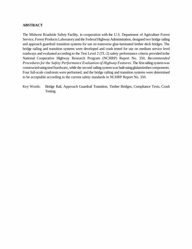
ABSTRACT
The Midwest Roadside Safety Facility, in cooperation with the U.S. Department of Agriculture ForestService, Forest Products Laboratory and the Federal Highway Administration, designed two bridge railingand approach guardrail transition systems for use on transverse glue-laminated timber deck bridges. Thebridge railing and transition systems were developed and crash tested for use on medium service levelroadways and evaluated according to the Test Level 2 (TL-2) safety performance criteria provided in theNational Cooperative Highway Research Program (NCHRP) Report No. 350, RecommendedProcedures for the Safety Performance Evaluation of Highway Features. The first railing system wasconstructed using steel hardware, while the second railing system was built using glulam timber components.Four full-scale crash tests were performed, and the bridge railing and transition systems were determinedto be acceptable according to the current safety standards in NCHRP Report No. 350.
Key Words: Bridge Rail, Approach Guardrail Transition, Timber Bridges, Compliance Tests, CrashTesting

3
INTRODUCTION
Problem Statement
For more than 30 years, numerous bridge railing systems have been developed and evaluated accordingto established vehicular crash testing standards. Most of the bridge railings previously tested have consistedof concrete, steel, and aluminum railings attached to concrete bridge decks. It is well known that a growingnumber of timber bridges with transverse and longitudinal timber bridge decks are being constructedthroughout the country. Therefore, the demand for crashworthy railing systems has become more evidentwith the increasing use of timber deck bridges located on secondary highways, county roads, and localroads. During the past eleven years, several crashworthy bridge railing systems were developed for use onlongitudinal timber deck bridges and for multiple service levels, ranging from low-speed, low-volume roadsto higher service level roadways. In addition, one recent research study led to the development of twohigher performance level railing systems for use on transverse timber deck bridges. However, little researchhas been conducted to develop crashworthy railings for use on transverse timber deck bridges located onlow to medium service level roadways. For timber to be a viable and economical alternative in theconstruction of transverse timber decks, additional railing systems must be developed and crash tested fortimber deck bridges located on these roadways.
In recognition of the need to develop bridge railing systems for this medium service level, the UnitedStates Department of Agriculture (USDA) Forest Service, Forest Product Laboratory (FPL), incooperation with the Midwest Roadside Safety Facility (MwRSF) and the Federal Highway Administration(FHWA), undertook the task of developing two medium service level bridge railings and approachguardrail transitions.
Research Objective
The primary objective of this research project was to develop and evaluate two bridge railings andapproach guardrail transitions for use on transverse glue-laminated (glulam) timber deck bridges locatedon medium service level roadways. The bridge railing and transitions systems were developed to meet theTest Level 2 (TL-2) evaluation criteria described in the National Cooperative Highway Research Program(NCHRP) Report No. 350, Recommended Procedures for the Safety Performance Evaluation ofHighway Features (1).
The first bridge railing, referred to as System No. 1, was a steel system that was constructed witha thrie beam rail, an upper structural channel rail, and wide-flange posts and blockouts. Photographs of thesteel bridge railing system and the attached thrie beam approach guardrail transition are provided in Figure1. The second bridge railing, referred to as System No. 2, was a wood system that was constructed usinga rectangular rail, posts, and blockouts, all of which were manufactured from glulam timber. Photographsof the wood bridge railing system and the attached W-beam approach guardrail transition are provided inFigure 2.

4
Another objective of the research project was to determine the forces imparted to key componentsof the bridge railing systems during impact of the test vehicles. Knowledge of these force levels can allowresearchers and engineers to make minor modifications to the crash tested designs without additional full-scale crash testing, and it provides insight into the development of future systems.
Research Plan
The research objectives were accomplished with the successful completion of several tasks. First, aliterature search was performed to review the previously-developed, low to medium performance levelbridge railing systems, as well as bridge railings developed for timber deck bridges. This review wasdeemed necessary because it was envisioned that the two new bridge railing designs would likely usetechnologies and design details from existing crashworthy railing systems. Second, bridge railing conceptswere prepared so that an analysis and design phase could be performed on all structural members andconnections.
Subsequently, computer simulation modeling was conducted using BARRIER VII to aid in theanalysis and design of the bridge railing and approach guardrail transition systems (2). For each bridgerailing system, strain gauge instrumentation was placed on selected structural components to help determinethe actual dynamic loads imparted into the bridge railing and deck systems. The researchers deemed thatthe dynamic load information was necessary because additional economy could be provided with thedownsizing of specific structural components.
Next, a total of four full-scale vehicle crash tests (two crash tests on each bridge railing andtransition system) were performed using ¾-ton pickup trucks. Test results were analyzed, evaluated, anddocumented. Conclusions and recommendations that pertain to the safety performance of each bridgerailing and transition system were then made.
BRIDGE RAILING HISTORY
The primary purpose of a bridge railing is to safely contain errant vehicles crossing a bridge. Therefore,railings must be designed to withstand the force of an impacting vehicle without endangering the occupantsin the vehicle and without significant damage to the bridge deck. In designing railing systems for highwaybridges, engineers have traditionally assumed that vehicle impact forces can be approximated by equivalentstatic loads that are applied to railing elements. Until recently, the American Association of State Highwayand Transportation Officials (AASHTO) Standard Specifications for Highway Bridges (3) required thatbridge railings be designed to resist an outward transverse static load of 44.5 kN. Despite the widespreaduse of design requirements based primarily on static load criteria, the need for more appropriate full-scalevehicle crash test criteria has long been recognized. The first U.S. guidelines for full-scale vehicle crashtesting were published in 1962 (4). In 1981, NCHRP published Report No. 230, RecommendedProcedures for the Safety Performance Evaluation of Highway Appurtenances (5). Thiscomprehensive report provided recommendations relative to crash testing and evaluation of longitudinal
5
barriers and served as the basis for future bridge rail crash testing requirements.
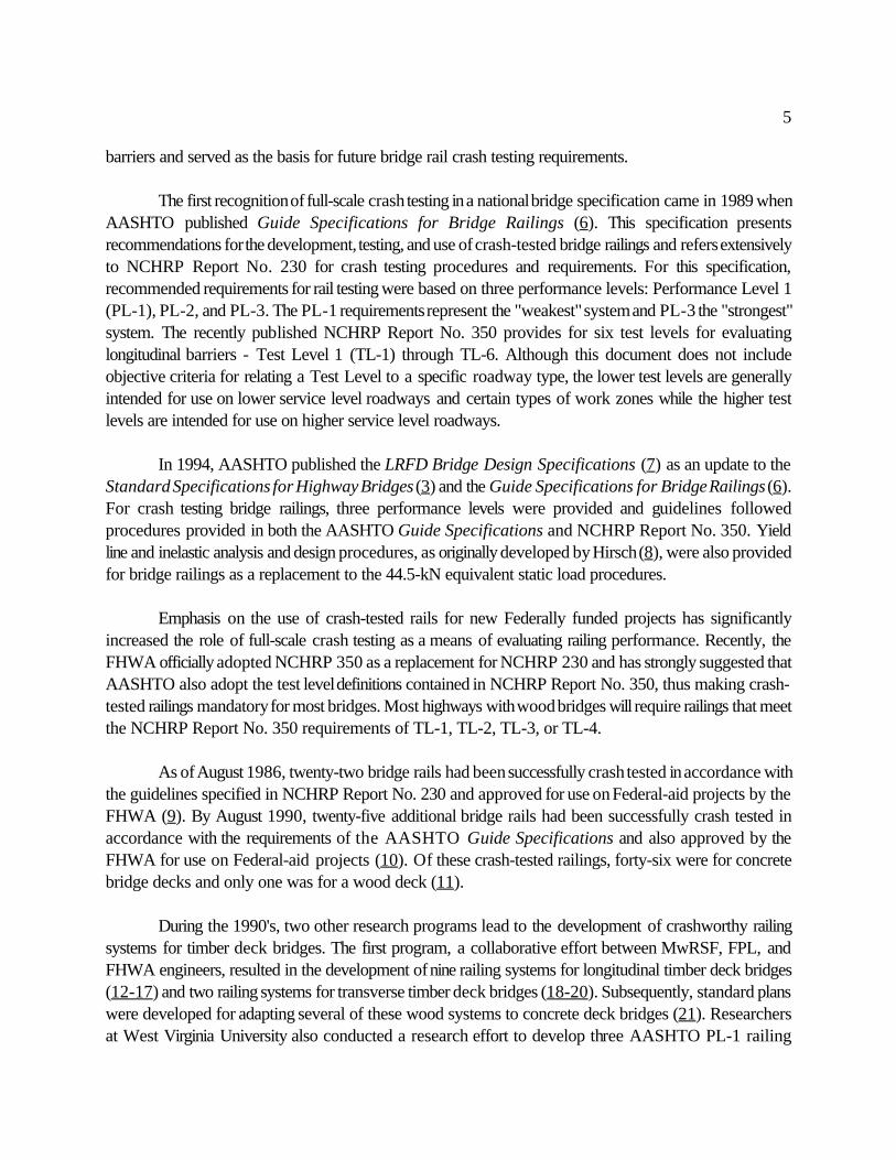
The first recognition of full-scale crash testing in a national bridge specification came in 1989 whenAASHTO published Guide Specifications for Bridge Railings (6). This specification presentsrecommendations for the development, testing, and use of crash-tested bridge railings and refers extensivelyto NCHRP Report No. 230 for crash testing procedures and requirements. For this specification,recommended requirements for rail testing were based on three performance levels: Performance Level 1(PL-1), PL-2, and PL-3. The PL-1 requirements represent the "weakest" system and PL-3 the "strongest"system. The recently published NCHRP Report No. 350 provides for six test levels for evaluatinglongitudinal barriers - Test Level 1 (TL-1) through TL-6. Although this document does not includeobjective criteria for relating a Test Level to a specific roadway type, the lower test levels are generallyintended for use on lower service level roadways and certain types of work zones while the higher testlevels are intended for use on higher service level roadways.
In 1994, AASHTO published the LRFD Bridge Design Specifications (7) as an update to theStandard Specifications for Highway Bridges (3) and the Guide Specifications for Bridge Railings (6).For crash testing bridge railings, three performance levels were provided and guidelines followedprocedures provided in both the AASHTO Guide Specifications and NCHRP Report No. 350. Yieldline and inelastic analysis and design procedures, as originally developed by Hirsch (8), were also providedfor bridge railings as a replacement to the 44.5-kN equivalent static load procedures.
Emphasis on the use of crash-tested rails for new Federally funded projects has significantlyincreased the role of full-scale crash testing as a means of evaluating railing performance. Recently, theFHWA officially adopted NCHRP 350 as a replacement for NCHRP 230 and has strongly suggested thatAASHTO also adopt the test level definitions contained in NCHRP Report No. 350, thus making crash-tested railings mandatory for most bridges. Most highways with wood bridges will require railings that meetthe NCHRP Report No. 350 requirements of TL-1, TL-2, TL-3, or TL-4.
As of August 1986, twenty-two bridge rails had been successfully crash tested in accordance withthe guidelines specified in NCHRP Report No. 230 and approved for use on Federal-aid projects by theFHWA (9). By August 1990, twenty-five additional bridge rails had been successfully crash tested inaccordance with the requirements of the AASHTO Guide Specifications and also approved by theFHWA for use on Federal-aid projects (10). Of these crash-tested railings, forty-six were for concretebridge decks and only one was for a wood deck (11).
During the 1990's, two other research programs lead to the development of crashworthy railingsystems for timber deck bridges. The first program, a collaborative effort between MwRSF, FPL, andFHWA engineers, resulted in the development of nine railing systems for longitudinal timber deck bridges(12-17) and two railing systems for transverse timber deck bridges (18-20). Subsequently, standard planswere developed for adapting several of these wood systems to concrete deck bridges (21). Researchersat West Virginia University also conducted a research effort to develop three AASHTO PL-1 railing

6
systems for transverse wood decks (22).
TEST REQUIREMENTS AND EVALUATION CRITERIA
According to the TL-2 criteria of NCHRP Report No. 350, longitudinal barriers must be subjected to twofull-scale vehicle crash tests: (1) an 820-kg small car impacting at a speed of 100.0 km/hr and at an angleof 20 degrees; and (2) a 2,000-kg pickup truck impacting at a speed of 100.0 km/hr and at an angle of25 degrees. For this research project, crash tests were performed using only the pickup truck impactconditions. Although the small car test is used to evaluate the overall performance of the length-of-needsection and to assess occupant risk problems that arise from snagging or overturing of the vehicle, it wasdeemed unnecessary for several reasons.
First, during the design of both barrier systems, special attention was given to prevent geometricincompatibilities that would cause the small car tests to fail as a result of excessive snagging or overturning.Second, the structural adequacy of the medium service level barrier systems is not a concern for the smallcar test due to the relatively minor impact severity as compared to the impact severity for the pickup truckimpact conditions. The impact severity for the pickup truck test is approximately 270 percent greater thanthat provided by the small car test. Third, a small car crash test was successfully conducted on a similarwood bridge railing system previously developed by MwRSF (12). Finally, thrie beam barriers struck bysmall cars have been shown to meet safety performance standards and to be essentially rigid (23-25), withno significant potential for occupant risk problems that arise from snagging or overturning. For thesereasons, the small car crash test was considered unnecessary for the systems that were developed underthis research project.
Evaluation criteria for full-scale crash testing is based on three appraisal areas: (1) structuraladequacy; (2) occupant risk; and (3) vehicle trajectory after the collision. Criteria for structural adequacyare intended to evaluate the ability of the railing to contain, redirect, or allow controlled vehicle penetrationin a predictable manner. Occupant risk evaluates the degree of hazard to occupants of the impactingvehicle. Vehicle trajectory after collision is concerned with the path and final position of the impactingvehicle and the probable involvement of the impacting vehicle in secondary collisions. Note that thesecriteria address only the safety and dynamic performance of the barrier and do not include service criteriasuch as aesthetics, economics, bridge damage, or post-impact maintenance requirements. The evaluationcriteria are summarized in NCHRP Report No. 350.
DEVELOPMENT PHASE
Transverse Panels
Highway bridges using transverse timber decks and those requiring crash tested railing systems are mostcommonly constructed using glulam timber deck panels. Transverse glulam timber decks are constructedof panels that are oriented with the lumber length perpendicular to the direction of traffic. Individual lumber
7
laminations are placed edgewise and glued together with waterproof structural adhesives. These panels aretypically 1.22-m wide, 127 to 171-mm thick, and effectively act as a thin plate. To form the bridge deck,panels are placed side by side and are supported by longitudinal glulam or steel beams. These longitudinalbeams are designed to carry the vertical loads and are braced by either glulam or steel diaphragms in orderto provide lateral stiffness to the bridge structure. Given that the panel orientation is perpendicular to traffic,railing loads primarily introduce tension and bending in the panels parallel to the wood grain. Unlike thelongitudinal glulam timber decks, tension perpendicular to the wood grain is not a primary designconsideration.
Bridge Rail Design
The primary emphasis of the railing design process was to develop rails that would meet the requirementsof the NCHRP Report No. 350. In addition, it was determined that consideration should be given to: (1)the extent of probable damage to the structure after vehicle impact and the difficulty and cost of requiredrepairs; (2) the adaptability of the railing to different types of wood decks; (3) the cost of the rail systemto the user, including material, fabrication, and construction; (4) the ease of railing construction andmaintenance; and (5) bridge railing aesthetics.
The development phase concluded with the design of several railing and transition systems and thepreparation of plans and specifications for testing. The selection and design of these final systems werebased on a review of other railings that had been successfully crash tested, as well as those that arecurrently used on wood bridges but have not been crash tested. To the extent possible, feasible designswere evaluated using BARRIER VII computer simulation modeling (2). Although several computer modelswere used, it was sometimes difficult to adapt the programs for wood components because the behaviorand properties of the wood systems at ultimate loading were unknown.
For the wood railing system, six dynamic bogie tests were conducted on glulam timber posts. Thebase of each post was placed vertically into a rigid steel sleeve. For each test, the bogie vehicle impactedthe cantilevered post specimen at a prescribed height above the fixed base. The results from the bogie testsprovided valuable information deemed necessary for determining the size of the glulam posts as well asselected input parameters for the computer simulation analysis.
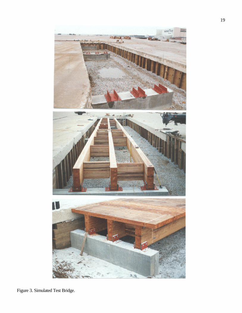
SIMULATED TEST BRIDGE
Testing of the bridge railing and approach guardrail transition systems was conducted at MwRSF’s outdoortest site located in Lincoln, Nebraska. To perform all the barrier testing, a full-size test bridge wasconstructed, as shown in Figure 3. The test bridge measured approximately 3.96-m wide and 36.58-m longand consisted of three simply-supported spans measuring approximately 12.19 m each.
The transverse deck system was constructed of 130-mm thick by 1.22-m wide glulam timberpanels. The glulam timber for the deck was Combination No. 47 Southern Yellow Pine, as specified in the
8
AASHTO LRFD Bridge Design Specification (7). The timber was treated according to the AmericanWood Preservers’ Association (AWPA) Standard C14 (26). Thirty glulam timber panels were placed sideby side to achieve the 36.58-m length and were attached to the longitudinal glulam beams with standardaluminum deck brackets.
The test bridge was positioned on concrete supports that were placed in a 2.13-m deep excavatedtest pit. The concrete supports were placed so that the top of the test bridge was 51 mm below theconcrete surface to allow for placement of the bridge deck wearing surface. A detailed discussion of thetest bridge is beyond the scope of this paper and is presented in detail by Fowler (20).
STEEL RAILING - SYSTEM NO. 1
Design Details
The first bridge railing system was designed as an all-steel system. This system was constructed with a thriebeam rail, an upper structural channel rail, wide-flange bridge posts and rail blockouts, and deck mountingplates. Specific details of this system are provided in Figure 4. For the steel system, a 10-gauge, thrie beamrail was blocked away from wide-flange posts with wide-flange spacers. A structural channel rail was thenattached to the top of the posts. The lower end of each post was bolted to two steel plates that wereconnected to the top and bottom surfaces of the bridge deck with vertical bolts.
System No. 1 was configured similarly to the TL-4 steel thrie beam and structural tube bridgerailing system previously developed for transverse decks (18-19). However, since the TL-2 impactcondition provided a reduced impact severity from the TL-4 impact condition, several design modificationswere deemed necessary. As a result, the upper structural tube rail on the TL-4 system was replaced witha channel rail section. This modification not only provided reduced weight but improved constructability.Other design modifications included a reduction in the size of the deck mounting plates as well as adecrease in the number of vertical bolts used to attach the mounting plates to the timber deck panels. A2,438-mm post spacing, also used with the TL-4 railings for transverse decks, was selected instead of theusual 1,905-mm post spacing. The increased post spacing was selected to optimize the design andsignificantly improve the constructability of the railing system, which was based on 1,219-mm wide deckpanels. Researchers believed these changes in the bridge railing design were necessary in order to provideadditional economy over the TL-4 bridge railing system.
During the railing development, researchers considered whether to design the bridge railing withor without the upper channel rail section. If an upper channel rail was not used, dynamic deflections wouldlikely be excessive, thus potentially resulting in vehicle pocketing between bridge posts or vehicle rolloverupon redirection. If an upper channel rail was used, then greater load distribution would occur between thebridge posts, thus resulting in the reduced pocketing and improved stability of the pickup truck uponredirection. For the final system, a more conservative design approach was chosen, and the upper channelrail was retained.

9
A TL-2 approach guardrail transition system was designed for attachment to each end of the bridgerailing system. The system was constructed using a steel thrie beam rail, a sloped structural channel end rail,guardrail posts, and rail blockouts. Specific details of the approach guardrail transition used with SystemNo.1 are provided in Figure 5.
Bridge Rail Crash Test
The steel bridge railing system was subjected to one full-scale vehicle crash test. Details of the crash testare provided in the following section. It is noted that instrumentation sensors were strategically placed onselected bridge railing components. However, a detailed discussion of the instrumentation results is beyondthe scope of this paper and will be provided in future publications.
The first crash test, test STCR-1, was successfully performed with a 1990 Chevrolet 2500, ¾-tonpickup truck with a test inertial mass of 1,966 kg and at the impact conditions of 66.6 km/hr and 25.6degrees. During the impact event, the truck became parallel to the railing at 0.229 sec and with a speedof 46.1 km/hr. At 0.519 sec after impact, the vehicle exited the railing system at a speed of 45.2 km/hr andat an angle of 14.7 degrees. The maximum lateral permanent set and dynamic rail deflections wereobserved to be 102 and 157 mm, respectively. The location of the vehicle impact with the bridge railing,vehicle damage, and barrier damage are shown in Figure 6.
Following an analysis of the test results, it was determined that the steel bridge railing system metthe TL-2 safety performance criteria provided in NCHRP Report No. 350. No significant damage to thetest bridge was evident from the vehicle impact test. For the bridge railing system, damage consistedprimarily of permanent deformation of the thrie beam rail, channel rail, wide-flange posts, and rail spacers.Although visual permanent set deformations of the steel components were found in the vicinity of the impact,all of the steel members remained intact and serviceable after the test. Thus, replacement of bridge railingcomponents would be based more on aesthetics versus structural integrity.
Transition Crash Test
The approach guardrail transition that is used with the steel bridge railing system was also subjected to onefull-scale vehicle crash test. Details of the crash test are provided in the following section.
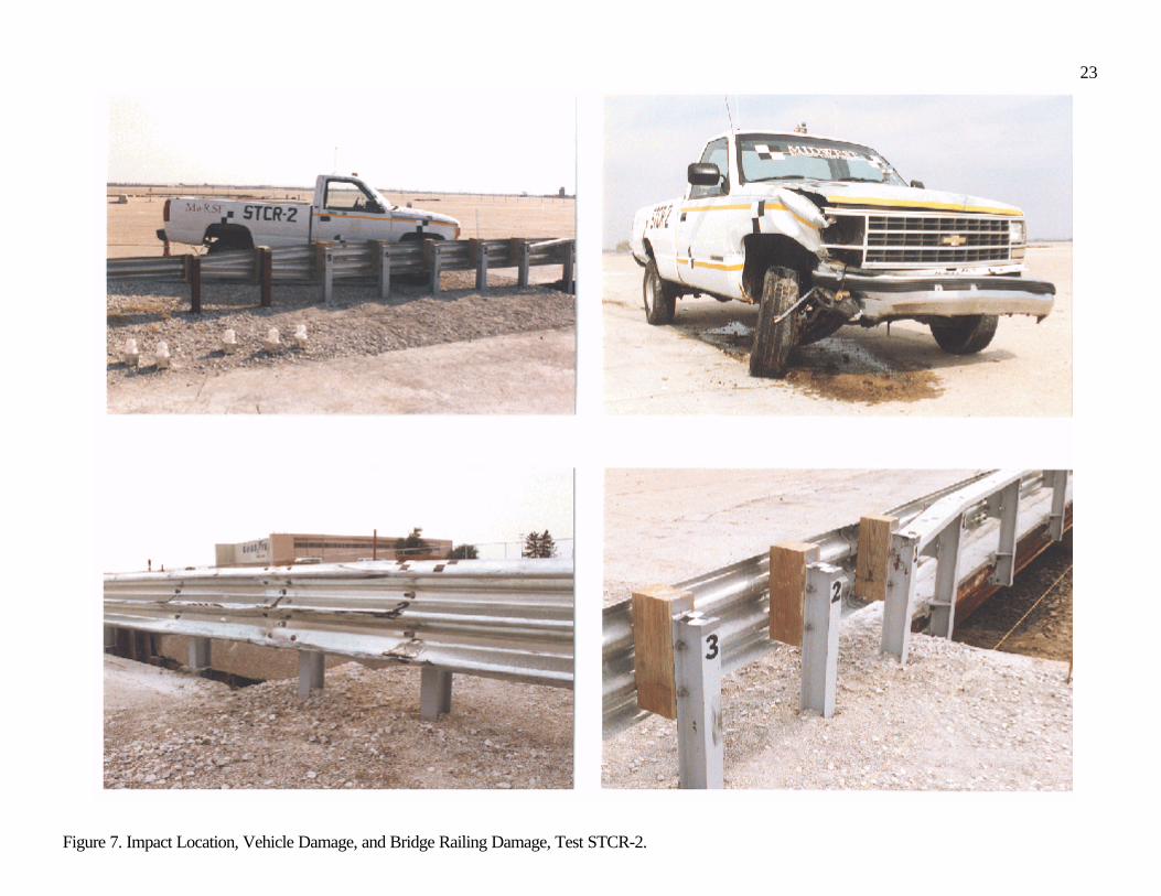
The first crash test, test STCR-2, was successfully performed with a 1990 Chevrolet 2500, ¾-tonpickup truck with a test inertial mass of 2,035 kg and at the impact conditions of 69.9 km/hr and 25.8degrees. During the impact event, the truck became parallel to the railing at 0.272 sec and with a speedof 50.0 km/hr. At 0.500 sec after impact, the vehicle exited the transition system at a speed of 45.5 km/hrand at an angle of 17.6 degrees. The maximum lateral permanent set and dynamic rail deflections wereobserved to be 117 and 202 mm, respectively. The location of the vehicle impact with the approachguardrail transition, vehicle damage, and barrier damage are shown in Figure 7.

10
Following an analysis of the test results, it was determined that the approach guardrail transition foruse with the steel bridge railing system met the TL-2 safety performance criteria provided in NCHRPReport No. 350. No significant damage to the upstream end of the test bridge was evident from the vehicleimpact test. For the approach guardrail transition system, damage consisted primarily of deformed thriebeam rail and bridge posts as well as displaced guardrail posts. Although visual permanent set deformationsof the thrie beam rail were found in the vicinity of the impact, the rail remained intact and serviceable afterthe test. Thus, replacement of the guardrail would be based more on aesthetics versus structural integrity.
WOOD RAILING - SYSTEM NO. 2
Design Details
The second bridge railing system was designed to be an all-wood system, except for the structural steelconnections. This system was constructed using a rectangular rail, rectangular bridge posts, rail blockouts,and deck mounting plates. Specific details of this system are provided in Figure 8. For the wood system,glulam timber for the rail and post members was Combination No. 48 Southern Yellow Pine (SYP), asspecified in AASHTO’s LRFD Bridge Design Specifications (7), and treated with pentachlorophenol inheavy oil to AWPA Standard C14 requirements (26). Glulam timber for the spacer blocks were fabricatedwith Combination No. 47 SYP, as specified by AASHTO (7) and treated in the same manner as describedpreviously according to AWPA Standard C14 (26).
System No. 2 was configured similarly to the PL-1 glulam timber rail without curb systempreviously developed for longitudinal decks (12,15-16,18). However, for this system, all woodcomponents were fabricated from glulam timber, whereas the previous system used glulam rail and sawnlumber posts and blocks. From the PL-1 railing system, the steel box that was used to support the postswas replaced with a more economical steel, U-shaped bracket which attached to the deck surface. Inaddition, all structural members, as well as the steel hardware, were resized to account for the increasedpost spacing from 1,905 to 2,438 mm. Once again, the new post spacing was selected to optimize thedesign and improve the constructability of the railing system, which was based on 1,219-mm wide deckpanels.
A TL-2 approach guardrail transition system was designed for attachment to each end of the bridgerailing system. The system was constructed using two nested steel W-beam rails, guardrail posts, and railblockouts. Specific details of the approach guardrail transition used with System No.2 are provided inFigure 9.
Bridge Rail Crash Test
The wood bridge railing system was subjected to one full-scale vehicle crash test. Details of crash test areprovided in the following section. It is noted that instrumentation sensors were strategically placed onselected bridge railing components. However, a detailed discussion of the instrumentation results is beyond
11
the scope of this paper and will be provided in future publications.
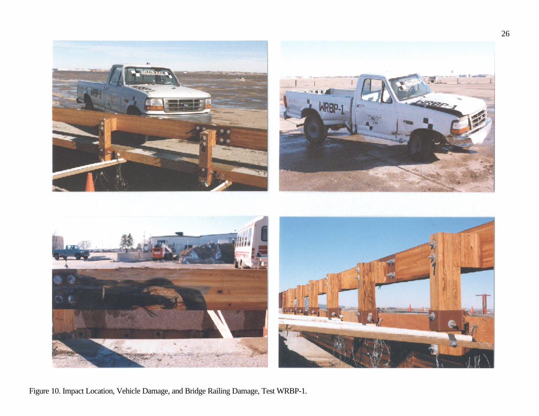
The first crash test, test WRBP-1, was successfully performed with a 1994 Ford F-250, ¾-tonpickup truck with a test inertial mass of 2,031 kg and at the impact conditions of 69.0 km/hr and 26.2degrees. During the impact event, the truck became parallel to the railing at 0.280 sec and with a speedof 47.2 km/hr. At 0.452 sec after impact, the vehicle exited the railing system at a speed of 47.1 km/hr andat an angle of 5.9 degrees. The maximum lateral permanent set and dynamic rail deflections were observedto be 63 and 189 mm, respectively. The location of the vehicle impact with the bridge railing, vehicledamage, and barrier damage are shown in Figure 10.
Following an analysis of the test results, it was determined that the wood bridge railing system metthe TL-2 safety performance criteria provided in NCHRP Report No. 350. No significant damage to thetest bridge was evident from the vehicle impact test. For the bridge railing system, damage consistedprimarily of rail gouging and scraping as well as permanent set deformations of the steel deck mountingplates. The glulam timber railing remained intact and serviceable after the test. Railing replacement wouldnot be considered necessary unless to provide improved aesthetics.
Transition Crash Test
The approach guardrail transition that is used with wood bridge railing system was also subjected to onefull-scale vehicle crash test. Details of crash test are provided in the following section.
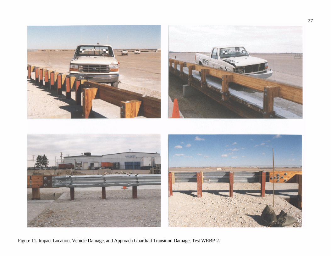
The first crash test, test WRBP-2, was successfully performed with a 1993 Ford F-250, ¾-tonpickup truck with a test inertial mass of 2,011 kg and at the impact conditions of 71.6 km/hr and 26.3degrees. During the impact event, the truck became parallel to the railing at 0.261 sec and with a speedof 55.9 km/hr. At 0.422 sec after impact, the vehicle exited the transition system at a speed of 54.6 km/hrand at an angle of 3.5 degrees. The maximum lateral permanent set and dynamic rail deflections wereobserved to be 29 and 125 mm, respectively. The location of the vehicle impact with the approachguardrail transition, vehicle damage, and barrier damage are shown in Figure 11.
Following an analysis of the test results, it was determined that the approach guardrail transition foruse with the wood bridge railing system met the TL-2 safety performance criteria provided in NCHRPReport No. 350 (1). No significant damage to the upstream end of the test bridge was evident from thevehicle impact test. For the approach guardrail transition system, damage consisted primarily of deformedW-beam rail and displaced guardrail posts. Although visual permanent set deformations of the W-beamrail were found in the vicinity of the impact, the rail remained intact and serviceable after the test. Thus,replacement of guardrail would be based more on aesthetics versus structural integrity.
DISCUSSION AND RECOMMENDATIONS
As stated previously, the researchers installed instrumentation sensors on key components of the railing

12
systems in an attempt to measure the actual forces imparted into the timber deck. The researchers deemedthat the dynamic load information was necessary because additional economy could be provided with thedownsizing of specific structural components.
For the steel system, eight 22-mm diameter ASTM A307 bolts were used to attach the steelmounting plates to the top and bottom surfaces of the timber deck. Measured strain readings on the platesnear the outer bolt locations were found to be significantly lower than those observed near the central boltlocations. In addition, no bearing deformations of the deck mounting plates and vertical bolts, nor damageto the timber deck near the shear connectors, were found. Therefore, the researchers believe that the TL-2steel bridge railing system would have performed in an acceptable manner if each deck plate was attachedwith only six vertical bolts instead of eight. It is noted that strain gauge results were used in a similar mannerwhen the number of vertical bolts were reduced in the TL-4 steel bridge railing system (19). However, fora reduction of two vertical bolts, there exists the potential for a slight increase in deck damage as well asincreased difficulty in removing and repairing the plates and bolts following an impact.
For the wood system, six 22-mm diameter ASTM A307 bolts were used to attach the steelmounting plates to the top and bottom surfaces of the timber deck. For the three top plates that wereinstrumented, measured strain readings showed that the load was better distributed throughout each plateand to all six of the vertical bolts. As a result, no design changes were believed to be necessary.
CONCLUSIONS
Two bridge railing and approach guardrail transition systems were successfully developed for use ontransverse glue-laminated (glulam) timber deck bridges located on medium service level roadways. Thebridge railing and transition systems were evaluated according to the TL-2 guidelines presented in NCHRPReport No. 350. For all crash tests, the bridge railing and transition systems performed well with nodamage to the bridge superstructure. With the development of the two crashworthy railing systems, asignificant barrier to the widespread use of transverse wood deck bridges on medium service levelroadways has been overcome. At the onset of this research program, no TL-2 crash tested bridge railingsystem was available for use on 130-mm thick, transverse wood deck bridges, although two TL-4 railingsystems had previously been developed (19). Now, bridge engineers have two railing systems for use ontransversely-laminated timber deck bridges located on medium service level roadways, and an approachguardrail transition system has been developed and crash tested for use with each bridge railing system.
ACKNOWLEDGMENTS
The authors wish to thank the following organizations which have contributed to the overall success of thisproject: the Forest Products Laboratory, Madison, WI; the Federal Highway Administration, Washington,D.C.; Alamco Wood Products, Inc., Albert Lea, MN; Hughes Brothers, Seward, NE; and the Office ofSponsored Programs and Center for Infrastructure Research, University of Nebraska-Lincoln, Lincoln,NE. Finally, special thanks to all of the MwRSF personnel for constructing the bridge structures and

13
barriers and for conducting the crash tests.
DISCLAIMER
The contents of this paper reflect the views of the authors who are responsible for the facts and theaccuracy of the data presented herein. The contents do not necessarily reflect the official views or policiesof FPL or FHWA. This report does not constitute a standard, specification, or regulation.
REFERENCES
1. Ross, H.E., Jr., Sicking, D.L., Zimmer, R.A., and Michie, J.D., Recommended Procedures forthe Safety Performance Evaluation of Highway Features, National Cooperative HighwayResearch Program (NCHRP) Report No. 350, National Research Council, TransportationResearch Board, Washington, D.C., 1993.
2. Powell, G.H., BARRIER VII: A Computer Program for Evaluation of Automobile BarrierSystems, Report FHWA RD-73-51, Federal Highway Administration, U.S. Department ofTransportation, April 1973.
3. Standard Specifications for Highway Bridges, American Association of State Highway andTransportation Officials (AASHTO), Washington, D.C., 1989.
4. Full-Scale Testing Procedures for Guardrails and Guide Posts, Highway Research CircularNo. 482, National Research Council, Highway Research Board, National Cooperative HighwayResearch Program, Washington, D.C., 1962.
5. Michie, J.D., Recommended Procedures for the Safety Performance Evaluation of HighwayAppurtenances, National Cooperative Highway Research Program (NCHRP) Report No. 230,National Research Council, Transportation Research Board,, Washington, DC, 1981.
6. Guide Specifications for Bridge Railings, American Association of State Highway andTransportation Officials (AASHTO), Washington, D.C., 1989.
7. AASHTO LRFD Bridge Design Specifications, First Edition, American Association of StateHighway and Transportation Officials (AASHTO), Washington, D.C., 1994.
8. Hirsch, T.J., Analytical Evaluation of Texas Bridge Rails to Contain Buses and Trucks, ReportNo. FHWA/TX78-230-2, Submitted to Texas State Department of Highways and PublicTransportation, Texas Transportation Institute, Texas A&M University, August 1978.

14
9. Memorandum on Bridge Rails, August 28, 1986, File Designation HNG-10/HHS-10, FederalHighway Administration (FHWA), Washington, D.C., 1986.
10. Memorandum on Crash Tested Bridge Railings, August 13, 1990, File Designation HNG-14,Federal Highway Administration (FHWA), Washington, D.C., 1990.
11. Hancock, K.L., Hansen, A.G., and Mayer, J.B., Aesthetic Bridge Rails, Transitions, andTerminals for Park Roads and Parkways, Report No. FHWA-RD-90-052, Submitted to Officeof Safety and Traffic Operations R&D, Federal Highway Administration, Performed by TheScientex Corporation, May 1990.
12. Faller, R.K., Ritter, M.A., Holloway, J.C., Pfeifer, B.G., and Rosson, B.T., Performance Level1 Bridge Railings for Timber Decks, Transportation Research Record 1419, TransportationResearch Board, National Research Council, Washington, D.C., October 1993.
13. Rosson, B.T., Faller, R.K., and Ritter, M.A., Performance Level 2 and Test Level 4 BridgeRailings for Timber Decks, Transportation Research Record 1500, Transportation ResearchBoard, National Research Council, Washington, D.C., July 1995.
14. Faller, R.K., Rosson, B.T., Ritter, M.A., and Sicking, D.L., Design and Evaluation of Two Low-Volume Bridge Railings, Sixth International Conference on Low-Volume Roads, Volume 2,Conference Proceedings 6, University of Minnesota, Minneapolis, Minnesota, June 25-29, 1995,Transportation Research Board, Washington, D.C., 1995.
15. Ritter, M.A., Lee, P.D.H., Faller, R.K., Rosson, B.T., and S.R. Duwadi, Plans for Crash TestedBridge Railings for Longitudinal Wood Decks, General Technical Report No. FPL-GTR-87,United States Department of Agriculture, Forest Service, Forest Products Laboratory, Madison,Wisconsin, September 1995.
16. Faller, R.K., Rosson, B.T., Ritter, M.A., Lee, P.D.H., and Duwadi, S.R., Railing Systems forLongitudinal Timber Deck Bridges, Presented at the National Conference on WoodTransportation Structures, Madison, Wisconsin, October 23-25, 1996, General Technical ReportNo. FPL-GTR-94, United States Department of Agriculture - Forest Service - Forest ProductsLaboratory and Federal Highway Administration, October 1996.
17. Ritter, M.A., Faller, R.K., Bunnell, S., Lee, P.D.H., and Rosson, B.T., Plans for Crash-TestedRailings for Longitudinal Wood Decks on Low-Volume Roads, General Technical Report No.FPL-GTR-107, United States Department of Agriculture - Forest Service - Forest ProductsLaboratory and Federal Highway Administration, August 1998.
15
18. Faller, R.K., Rosson, B.T., Ritter, M.A., and Duwadi, S.R., Railing Systems for Use on TimberDeck Bridges, Transportation Research Record No. 1656, Transportation Research Board,Washington, D.C., July 1999, 110-119.
19. Faller, R.K., Ritter, M.A., Rosson, B.T., Fowler, M.D., and Duwadi, S.R., Two Test Level 4Bridge Railing and Transition Systems for Transverse Timber Deck Bridges, Paper No.5B0110, Transportation Research Record No. 1996, Volume 1, Fifth International BridgeEngineering Conference, Tampa, Florida, April 3-5, 2000, Transportation Research Board,Washington, D.C., 334-351.
20. Fowler, M.D., Design and Testing of a Test Level 4 Bridge Railing for Transverse GlulamTimber Deck Bridges, M.S. Thesis, University of Nebraska-Lincoln, May 1997.
21. Ritter, M.A., Faller, R.K., Lee, P.D.H., Rosson, B.T., and Duwadi, S.R., Plans for Crash-TestedWood Bridge Railings for Concrete Decks, General Technical Report No. FPL-GTR-108,United States Department of Agriculture - Forest Service - Forest Products Laboratory andFederal Highway Administration, August 1998.
22. Raju, P., R., GangaRao, H.V.S., Duwadi, S.R., and Thippeswamy, H.K., Development andTesting of Timber Bridge and Transition Rails for Transverse Glued-Laminated BridgeDecks, Transportation Research Record 1460, Transportation Research Board, NationalResearch Council, Washington, D.C., December 1994.
23. Buth, C.E., Campise, W.L., Griffin, III, L.I., Love, M.L., and Sicking, D.L., Performance Limitsof Longitudinal Barrier Systems - Volume I - Summary Report , Report No. FHWA/RD-86/153, Submitted to the Office of Safety and Traffic Operations, Federal Highway Administration,Performed by Texas Transportation Institute, May 1986.
24. Ivey, D.L., Robertson, R., and Buth, C.E., Test and Evaluation of W-Beam and Thrie-BeamGuardrails, Report No. FHWA/RD-82/071, Submitted to the Office of Research, FederalHighway Administration, Performed by Texas Transportation Institute, March 1986.
25. Ross, H.E., Jr., Perera, H.S., Sicking, D.L., and Bligh, R.P., Roadside Safety Design for SmallVehicles, National Cooperative Highway Research Program (NCHRP) Report No. 318,Transportation Research Board, Washington, D.C., May 1989.
26. AWPA Book of Standards, American Wood Preservers' Association (AWPA), Woodstock, MD,1992.
16
List of Figures
Figure 1. Steel Thrie Beam with Channel Bridge Railing and Thrie Beam with Channel Transition, SystemNo. 1.
Figure 2. Glulam Rail Bridge Railing and W-Beam Transition, System No. 2.
Figure 3. Simulated Test Bridge.
Figure 4. Steel Bridge Railing Design Details, System No. 1 (1 in. = 25.4 mm).
Figure 5. Approach Guardrail Transition Design Details, System No. 1 (1 in. = 25.4 mm).
Figure 6. Impact Location, Vehicle Damage, and Bridge Railing Damage, Test STCR-1.
Figure 7. Impact Location, Vehicle Damage, and Bridge Railing Damage, Test STCR-2.
Figure 8. Wood Bridge Railing Design Details, System No. 2 (1 in. = 25.4 mm).
Figure 9. Approach Guardrail Transition Design Details, System No. 2 (1 in. = 25.4 mm).
Figure 10. Impact Location, Vehicle Damage, and Bridge Railing Damage, Test WRBP-1.
Figure 11. Impact Location, Vehicle Damage, and Approach Guardrail Transition Damage, Test WRBP-2.

17
Figure 1. Steel Thrie Beam with Channel Bridge Railing and Thrie Beam with Channel Transition, System No. 1.

18
Figure 2. Glulam Bridge Railing and W-Beam Transition, System No. 2.
19
Figure 3. Simulated Test Bridge.

20
Figure 4. Steel Bridge Railing Design Details, System No. 1 (1 in. = 25.4 mm).

21
Figure 5. Approach Guardrail Transition Design Details, System No. 1 (1 in. = 25.4 mm).

22
Figure 6. Impact Location, Vehicle Damage, and Bridge Railing Damage, Test STCR-1.
23
Figure 7. Impact Location, Vehicle Damage, and Bridge Railing Damage, Test STCR-2.

24
Figure 8. Wood Bridge Railing Design Details, System No. 2 (1 in. = 25.4 mm).

25
Figure 9. Approach Guardrail Transition Design Details, System No. 2 (1 in. = 25.4 mm).
26
Figure 10. Impact Location, Vehicle Damage, and Bridge Railing Damage, Test WRBP-1.
27
Figure 11. Impact Location, Vehicle Damage, and Approach Guardrail Transition Damage, Test WRBP-2.