Embed Size (px)
Citation preview

University of Central Florida University of Central Florida
STARS STARS
Electronic Theses and Dissertations, 2004-2019
2013
Development Of The Strategy To Select Optimum Reflective Development Of The Strategy To Select Optimum Reflective
Cracking Mitigation Methods For The Hot-mix Asphalt Overlays In Cracking Mitigation Methods For The Hot-mix Asphalt Overlays In
Florida Florida
Hamid Maherinia University of Central Florida
Part of the Civil Engineering Commons, and the Structural Engineering Commons
Find similar works at: https://stars.library.ucf.edu/etd
University of Central Florida Libraries http://library.ucf.edu
This Masters Thesis (Open Access) is brought to you for free and open access by STARS. It has been accepted for
inclusion in Electronic Theses and Dissertations, 2004-2019 by an authorized administrator of STARS. For more
information, please contact [email protected].
STARS Citation STARS Citation Maherinia, Hamid, "Development Of The Strategy To Select Optimum Reflective Cracking Mitigation Methods For The Hot-mix Asphalt Overlays In Florida" (2013). Electronic Theses and Dissertations, 2004-2019. 2860. https://stars.library.ucf.edu/etd/2860

DEVELOPMENT OF THE STRATEGY TO SELECT OPTIMUM REFLECTIVE CRACKING
MITIGATION METHODS FOR THE HOT-MIXED ASPHALT OVERLAYS IN FLORIDA
by
HAMID MAHERINIA
M.S. Islamic Azad University, 2010
B.S. Isfahan University of Technology, 2006
A thesis submitted in partial fulfillment of the requirements
for the degree of Master of Science
in the Department of Civil, Environmental, and Construction Engineering
in the College of Engineering and Computer Sciences
at the University of Central Florida
Orlando, Florida
Spring Term
2013
Major Professor: Boo Hyun Nam

ii
© 2013 Hamid Maherinia

iii
ABSTRACT
Hot Mix Asphalt (HMA) overlay is a major rehabilitation treatment for the existing
deteriorated pavements (both flexible and rigid pavements). Reflective cracking (RC) is the most
common distress type appearing in the HMA overlays which structurally and functionally
degrades the whole pavement structure, especially under high traffic volume. Although many
studies have been conducted to identify the best performing RC mitigation technique, the level of
success varies from premature failure to good performance in the field.
In Florida, Asphalt Rubber Membrane Interlayers (ARMIs) have been used as a RC
mitigation technique but its field performance has not been successful. In this study, the best
performing means to mitigate RC in the overlays considering Florida’s special conditions have
been investigated. The research methodology includes (1) extensive literature reviews regarding
the RC mechanism and introduced mitigation options, (2) nationwide survey for understanding
the current practice of RC management in the U.S., and (3) the development of decision trees for
the selection of the best performing RC mitigation method. Extensive literature reviews have
been conducted to identify current available RC mitigation techniques and the advantages and
disadvantages of each technique were compared. Lesson learned from the collected case studies
were used as input for the selection of the best performing RC mitigation techniques for
Florida’s roads. The key input parameters in selecting optimum mitigation techniques are: 1)
overlay characterization, 2) existing pavement condition, 3) base and subgrade structural
condition, 4) environmental condition and 5) traffic level. In addition, to understand the current

iv
practices how reflective cracking is managed in each state, a nationwide survey was conducted
by distributing the survey questionnaire (with the emphasis on flexible pavement) to all other
highway agencies. Based on the responses, the most successful method of treatment is to
increase the thickness of HMA overlay. Crack arresting layer is considered to be in the second
place among its users. Lack of cost analysis and low rate of successful practices raise the
necessity of conducting more research on this subject.
Considering Florida’s special conditions (climate, materials, distress type, and geological
conditions) and the RC mechanism, two RC mitigation techniques have been proposed: 1)
overlay reinforcement (i.e. geosynthetic reinforcement) for the existing flexible pavements and 2)
Stress Absorbing Membrane Interlayer (SAMI) for the existing rigid pavements. As the final
products of this study, decision trees to select an optimum RC mitigation technique for both
flexible and rigid pavements were developed. The decision trees can provide a detailed guideline
to pavement engineer how to consider the affecting parameters in the selection of RC mitigation
technique.

v
ACKNOWLEDGMENTS
I would like to acknowledge the support of Florida Department of Transportation
for generously funding this project. I am more than honored to be able to work on this
project.
I would like to express my deepest appreciation to my adviser, Dr. Boo Hyun
Nam, for his patience and guidance during these two years. Without his guidance and
persistent help this thesis would not have been possible.
I am very grateful to my advisor and the thesis committee chair for reviewing the
manuscript in spite of his very busy schedule and making several important suggestions
which enhanced the edition.
I am pleased to extent greeting to other committee members, Dr. Amir Hossein
Behzadan and Dr. Mehmet Omer Tatari for their valuable guidance and encouragements
extended to me.
I wish to express my thanks to Mr. Fariborz Lachini and Mr. Yiruma for
providing an inspiring and relaxing atmosphere during working on this study.

vi
TABLE OF CONTENT
LIST OF FIGURES ........................................................................................................... xi
LIST OF TABLES ........................................................................................................... xiv
CHAPTER 1: INTRODUCTION ..................................................................................... 1
1.1 Project Description .................................................................................... 1
1.2 Research Objectives .................................................................................. 2
1.3 Research Scopes ........................................................................................ 3
1.4 Research Methodology .............................................................................. 3
1.5 Organization of the Thesis ........................................................................ 4
CHAPTER 2: LITERATURE REVIEW .......................................................................... 6
2.1 Introduction ............................................................................................... 6
2.2 Reflective Cracking Mechanism ............................................................... 6
2.2.1 Crack Initiation under Traffic Load ..................................................... 7
2.2.2 Crack Initiation under Thermal Load .................................................. 8
2.2.3 Crack Initiation Due to PCC Curling ................................................. 10
2.3 Practical Reflective Cracking (RC) Mitigation Methods ........................ 11
2.3.1 HMA Overlay Modification .............................................................. 12
2.3.2 Overlay Reinforcement ...................................................................... 15

vii
2.3.3 Stress Absorbing Membrane Interlayer (SAMI) ................................ 16
2.3.4 Cushion Layer .................................................................................... 16
2.4 Reflective Cracking Mitigation Method Descriptions ............................ 17
2.4.1 Geosynthetics ..................................................................................... 17
2.4.2 Stress Absorbing Membrane Interlayer (SAMI) ................................ 18
2.5 Case Studies: Field Performance ............................................................ 20
2.5.1 Nevada Study ..................................................................................... 20
2.5.2 Mississippi Study ............................................................................... 21
2.5.3 Arizona Study .................................................................................... 22
2.5.4 Texas Study ........................................................................................ 23
2.5.5 Alabama Study ................................................................................... 25
2.5.6 Illinois Study ...................................................................................... 26
2.5.7 New Jersey Study ............................................................................... 28
2.5.8 Worldwide comparison study for fabrics ........................................... 30
2.6 Application of Decision Tree in RC Mitigation Studies ......................... 31
2.6.1 Why Utilizing Decision Tree? ........................................................... 31
2.6.2 Decision Tree in RC Mitigation Method’s Managements ................. 32

viii
2.7 Result of Conducted Survey for RC mitigation on Rigid and Composite
Pavements ………………………………………………………………………….33
2.7.1 Type of Base Course .......................................................................... 34
2.7.2 Shoulder Type .................................................................................... 34
2.7.3 Joint Spacing ...................................................................................... 34
2.7.4 HMA Overlay Design Methods ......................................................... 34
2.7.5 HMA Overlay Materials .................................................................... 35
2.7.6 Site Conditions ................................................................................... 36
2.8 Conclusion ............................................................................................... 36
CHAPTER 3: UNDERSTANDING THE FDOT PRSCTICES AND REFLECTIVE
CRACKING SURVEY RESULTS .................................................................................. 38
3.1 Introduction ............................................................................................. 38
3.2 Review of Florida DOT Experiences ...................................................... 39
3.3 Personal Interview with Pavement Expert .............................................. 41
3.4 Survey Questionnaire .............................................................................. 44
3.5 Survey Results ......................................................................................... 44
3.6 Survey Result Analysis ........................................................................... 57
3.7 Conclusion ............................................................................................... 59

ix
CHAPTER 4: POTENTIAL REFLECTIVE CRACKING MITIGATION METHOD
SELECTION. 60
4.1 Introduction ............................................................................................. 60
4.2 General Concepts .................................................................................... 60
4.3 Key Parameters on Reflective Cracking Performance ............................ 62
4.3.1 Overlay Thickness ............................................................................. 62
4.3.2 Existing Pavement Condition ............................................................ 62
4.3.3 Base/Subgrade Support Condition ..................................................... 63
4.3.4 Environmental Factor......................................................................... 63
4.3.1 Traffic Level ...................................................................................... 64
4.4 Florida’s Special Condition ..................................................................... 65
4.4.1 Top-Down Cracking .......................................................................... 65
4.4.2 Climate ............................................................................................... 66
4.5 Selecting of optimum RC Mitigation Method......................................... 69
4.5.1 Coefficient of Thermal Expansion ..................................................... 70
4.5.1 PCC Pavement and its Dominant Movements ................................... 72
4.5.2 Selection of an Optimum RC Mitigation Method .............................. 74
4.6 Conclusion ............................................................................................... 77

x
CHAPTER 5: DECISION TREES FOR REFLECTIVE CRACKING
MITIGATION………………………………………………………………………….79
5.1 Introduction ............................................................................................. 79
5.2 Developing Approach of the Decision Tree ............................................ 79
5.3 Decision Tree .......................................................................................... 82
5.3.1 Decision Tree for Flexible Pavement with Milling Option ............... 83
5.3.2 Decision Tree for Flexible Pavement with Pre-Overlay Repair
Recommendation ....................................................................................................... 84
5.3.3 Decision Tree for Rigid Pavements ................................................... 87
5.4 Conclusion ............................................................................................... 90
CHAPTER 6: SUMMARY AND CONCLUSION ........................................................ 91
6.1 Summary ................................................................................................. 91
6.2 Findings and Conclusions ....................................................................... 92
6.2.1 HMA Overlay over Flexible Pavement ............................................. 92
6.2.2 HMA Overlay over Rigid Pavements: ............................................... 93
6.3 Future Study ............................................................................................ 95
APPENDIX: DESCRIPTIVE SURVEY RESULTS ........................................................ 96
REFERENCES. .............................................................................................................. 118

xi
LIST OF FIGURES
Figure 1. 1 Joint Reflective Cracking ................................................................................. 2
Figure 2. 1 Crack Initiations at the Bottom of the Overlay Due to Traffic Loading
(Bennert, 2009) ................................................................................................................... 8
Figure 2. 2 Crack Initiation at the Bottom of the Overlay Due to Thermal Load (Bennert,
2009) ................................................................................................................................... 9
Figure 2. 3 Maximum Vertical Movement in PCC Slabs Due to Daily Temperature
Changes (Greene, 2012a) .................................................................................................. 10
Figure 2. 4 Maximum Horizontal Movement in PCC Slabs Due to Daily Temperature
Changes(Greene, 2012a) ................................................................................................... 10
Figure 2. 5 Crack Initiation at the Surface of HMA overlay Due to Excessive Curling
Load (Bennert, 2009) ........................................................................................................ 11
Figure 2. 6 Performance of Pavement for Various Pavement Thickness (Button1989) .. 15
Figure 2. 7 Reflective Cracking Relief Interlayer or Strata (Pavement Performance
Prediction Symposium, 2007) ........................................................................................... 19
Figure 2. 8 Asphalt Rubber Membrane Interlayer in a Pavement System (Caltrans Report,
2003) ................................................................................................................................. 20
Figure 2. 9 Time reflective cracking observed after placement of HMA overlay (Bennert
& Maher, 2007) ................................................................................................................. 33
xii
Figure 2. 10 LTPPBind recommendations for low-temperature performance grade at 98%
reliability (Bennert & Maher, 2007) ................................................................................. 35
Figure 3. 1 Time to Appear Reflective Cracking after the Placement of New Overlay. .. 46
Figure 3. 2 Reason of Selecting Reflective Cracking Mitigation Techniques .................. 47
Figure 3. 3 RC Method of Treatment and Satisfaction Level ........................................... 49
Figure 3. 4 Expectation from the Mitigation Methods to Last Prior to RC Observation . 50
Figure 3. 5 Key Input Factors to be Considered for Selecting the RC Mitigation Method
........................................................................................................................................... 51
Figure 3. 6 Typical Overlay thickness over RC mitigation methods (t=HMA overlay
thickness) .......................................................................................................................... 52
Figure 3. 7 The Most Successful method of RC Mitigation in each State ........................ 53
Figure 3. 8 Pavement Tests and Measurements Prior to Designing the HMA Overlay ... 54
Figure 3. 9 Typical Treatment Used to Prepare the Old Pavement Prior to HMA Overlay
........................................................................................................................................... 55
Figure 3. 10 Overlay Design Methods .............................................................................. 56
Figure 3. 11 Parameters to be considered for Selecting Minimum Overlay Thickness ... 56
Figure 4. 1 Reflective Cracking over Time for Sections Having Different Overlay
Thickness (Carmichael and Marienfeld, 1999). ................................................................ 62

xiii
Figure 4. 2 Time to Observe Reflective Cracking after Placing the HMA Overlay
(Bennert & Maher, 2007). ................................................................................................. 64
Figure 4. 3 FDOT Districts’ Borders (FDOT website) ..................................................... 69
Figure 4. 4 PCC Slab movements due to (a) Differential Vertical Movement and (b)
Curling Due to Thermal Changes ..................................................................................... 73
Figure 4. 5 Reflective cracking observation over time for the sections with various
mitigation methods (Button and Lytton, 2009)................................................................. 76
Figure 5. 1 Thinking Process of Developing Decision Trees for RC Mitigation Methods
........................................................................................................................................... 80
Figure 5. 2 Decision Tree for Flexible Pavement with Milling Option ........................... 85
Figure 5. 3 Decision Tree for Flexible Pavement with Pre-Overlay Recommendation ... 86
Figure 5. 4 Decision tree for Rigid Pavements ................................................................. 89

xiv
LIST OF TABLES
Table 2. 1Performance Grade of Asphalt Binder and Reflective Cracking Life of
Different States (Bennert & Maher, 2007) ....................................................................... 29
Table 3. 1 Reflective Cracking Management Survey Questionnaire ................................ 45
Table 3. 2 Selection Method of Reflective Cracking Mitigation Techniques .................. 46
Table 4. 1 Average Maximum Air Temperature During Summer in Florida ................... 67
Table 4. 2 Average Minimum Air Temperature during Winter in Florida ....................... 68
Table 4. 3Mean Value and Standard Deviation of Minimum and Maximum Temperatures
........................................................................................................................................... 68
Table 4. 4 Influence of Aggregate Content on CTE (Neville, 1996) ................................ 72
Table A. 1 Typical Overlay Thickness ............................................................................. 98
Table A. 2 Time after Construction to RC Appearance .................................................... 99
Table A. 3 RC Mitigation Method Use Experiencing and Its Performance ................... 100
Table A. 4 Explanation for Selecting the Mitigation Method ........................................ 103
Table A. 5 Criteria for Selecting an Appropriate RC Mitigation Method ...................... 105
Table A. 6 The Most Successful Mitigation Method ...................................................... 106
Table A. 7 Life Expectation of the Best Performing Mitigation Method ....................... 107
Table A. 8 Tests to Evaluate the Existing Pavement before Overlaying ........................ 109

xv
Table A. 9 Typical Treatments on Flexible Pavements before Placing HMA Overlay . 111
Table A. 10 Overlay Design Method ............................................................................ 113
Table A. 11 Expectation from an Applied Mitigation Method ....................................... 115
Table A. 12 Considering Life Cycle Analysis in Selecting the Method or Treatment ... 116
Table A. 13 Unite Cost of the Selected Method ............................................................ 117

1
CHAPTER 1: INTRODUCTION
1.1 Project Description
Reflective Cracking (RC) can be formed when a Hot Mix Asphalt (HMA) overlay
is placed on jointed or severely cracked rigid or flexible pavements (see Figure 1.1).
Creation of the RC on the HMA overlays can further develop other pavement distresses
such as stripping and weakening sublayer materials (base, subbase, and subgrade) by
allowing moisture infiltration. Therefore, there have been many attempts to prevent or
retard the initiation of the RC on HMA overlay. The range of success for various projects
is from failure to very successful depending on site condition along with a selected RC
mitigation technique.
Florida Department of Transportation (FDOT) has been using an Asphalt Rubber
Membrane Interlayer (ARMI) over nearly 20 years to reduce reflection cracking in the
HMA overlays. Although the ARMI is a common RC mitigation method in Florida, the
success of its field performance varies. Evaluating different projects in Florida, the
effectiveness of ARMI’s performance in terms of RC mitigation and instability rutting is
still suspicious. A study shows that ARMI not only delay the RC initiation on pavements,
but also increases the pace of RC appearance on the overlays. Moreover, several Florida
state districts suspect the performance o ARMI in contribution to rutting (Green, 2012).

2
Given the inconsistent performance of the ARMI, there is a need to identify
alternatives for replacing the primary RC mitigation method considering Florida’s special
conditions such as climate, binder and aggregate source, and top-down cracking.
Figure 1. 1 Joint Reflective Cracking
1.2 Research Objectives
The main objectives of this study are to understand the current practices of RC
management and to identify the adequate RC mitigation method for the state of Florida.
In order to achieve to this goal, the followings tasks have been accomplished:
Conducting a literature review to understand the deficiency of the
nationwide ongoing projects especially in Florida.
Finding the key parameters in RC mitigation method performance.
Developing a decision tree to select the most appropriate RC method to
resist, control or delay RC in HMA overlay.

3
1.3 Research Scopes
Research scopes of this study are as following:
Structural assessment of existing RC mitigation methods considering
Florida’s special conditions.
Development of recommendations for the best performing RC mitigation
methods.
Different methods of RC mitigation were identified through extensive publication
reviews. The success level of each method was evaluated and key affecting parameters on
crack initiation were identified. By studying Florida’s current practices on the RC
management and considering its special conditions (i.e., typical overlay type and climate),
optimum RC mitigation techniques have been proposed to accommodate identified
mechanism of RC initiation. A nationwide survey was also conducted to understand how
other state manage reflective cracking and also to obtain inputs for selecting the potential
RC mitigation alternative. For future work, conducting experimental tests is required to
evaluate the proposed potential RC mitigation techniques on both rigid and flexible
pavements.
1.4 Research Methodology
The research methodology involves literature reviews, nationwide survey, and the
development of decision trees. Decision tree is the most adequate solution for RC at
different distresses type and traffic circumstances. The objective of decision tree is
obtaining the most accurate prediction possible for RC mitigation methods by providing a

4
sequence of questions to find the solution. Thus, by applying conventional pavement
system evaluation and considering the roads traffic condition, a decision tree could be
established.
1.5 Organization of the Thesis
The following chapters of this thesis are shaped to achieve the aforementioned
goals and objectives. Thus, the organization of the thesis is as follows:
Chapter 1: Introduction- This chapter describes the overview and objectives of the
conducted research. Moreover, the study scope has been provided in this chapter.
Chapter 2: Literature Review- The focuses of this chapter are on the literature
reviews in the areas of: 1) understanding the mechanism of RC in flexible and rigid
pavements, 2) currently available RC mitigation techniques, 3) key affecting parameters
on the development and propagation of RC, and 4) case studies of each mitigation
technique used in the laboratory and field.
Chapter 3: Understanding FDOT Practices and Nationwide Survey- This chapter
defines the framework of the study to achieve the aforementioned goals in the first
chapter. Personal interviews and a nationwide survey on the RC management have been
conducted. Historical approaches and current practice on how FDOT manage the RC
mitigation were investigated. Moreover, Detailed and comprehensive analytical result of
the survey is being presented in this chapter.
Chapter 4: Potential Reflective Cracking Mitigation Method Selection- In this
chapter, RC mitigation methods have been proposed to be utilized on flexible and rigid

5
pavements. Selections of the methods were on the basis of RC initiation mechanism and
understanding of the material properties under Florida’s special conditions.
Chapter 5: Decision Tree- Decision trees which have been developed for both
rigid and flexible pavements are presented in this chapter. These decision trees are
developed in the way to be used as a RC mitigation method guideline considering
Florida’s special condition.
Chapter 6- Summary and Conclusion: This chapter summarizes the conducted
study on RC mitigation method. Later in this chapter a conclusion of the findings of the
project has been presented.

6
CHAPTER 2: LITERATURE REVIEW
2.1 Introduction
Results of this study strongly stand on good understanding of the RC mechanisms
and an extensive literature review. This chapter discusses about three main mechanisms
of RC initiation and propagation in the HMA overlay. RC mitigation techniques will be
categorized based on their type and RC retarding mechanism.
2.2 Reflective Cracking Mechanism
Reflective Cracking in asphalt pavement overlays occurs over the joints of
existing underlying concrete pavement or structural cracks in Hot Mix Asphalt (HMA)
pavements. It can also be created by traffic load or more generally, by differential
settlement where the old and new layers meet. Moreover, RC can be initiated by
expansion, contraction and bending from thermally induced movement of the layers. RC
reduces the service life of the pavements by introducing premature deterioration of the
pavement structure or other distresses that might be caused by water infiltration in the
overlay (e.g., weakening the load bearing capacity of the base layer and loosing bonds
between aggregates and asphalt binder).
The first process is mechanical cracking under traffic load when joints or cracks
constitute differential vertical deflections. To be more concise, this mechanism of
reflective cracking creates strain concentration in overlay. This strain may be result of

7
bending or shearing action resulting from traffic loads. The second process is
thermal cracking especially in locations with high daily temperature change. All these
two processes result in cracks reflection in overlay when the local tensile stress surpasses
the tensile strength of the HMA overlay (Fujie Zhou, Sheng Hu, Xiaodi Hu, 2009). The
combination of shear and bending forces from traffic load and thermal force due to daily
temperature changes can initiate RC on HMA overlays. Another common mechanism of
RC in rigid pavements is slab curling which leads to top down cracking in the overlay. In
the following sections, all the mentioned mechanisms will be discussed.
2.2.1 Crack Initiation under Traffic Load
Traffic load creates vertical movement in Portland Cement Concrete (PCC) slabs
when Load Transfer Efficiency (LTE) in transverse or longitudinal joints or at the crack
tips in HMA pavements is low. The differential vertical movement in joints or cracks
depresses adjacent slab’s ends resulting in shear stress in HMA overlay. The reflective
cracking by traffic load is shear-fatigue phenomenon which is dependent on the
magnitude of the differential vertical movement in joints or cracks. Thus, three important
parameters which are more significant in this mechanism are (Von Quintus, 2009):
1) Magnitude of the wheel load
2) Amount of load transfer across the joints or cracks
3) Differential subgrade support under the slab

8
Reflective cracking in this mechanism is bottom-up distress and crack initiates
from bottom of the overlay and propagates upwards. The schematic figure of this
mechanism and its associating bending and shear loads are shown in Figure 2.1.
Figure 2. 1 Crack Initiations at the Bottom of the Overlay Due to Traffic Loading
(Bennert, 2009)
2.2.2 Crack Initiation under Thermal Load
Thermally induced cracking occurs when temperature changes in existing
pavement in a short period of time. Daily temperature change can result in expansion and
contraction of layers and therefore results in horizontal movements. Tensile stress and
strain at the bottom of the overlay due to the horizontal movements is a potential cause of
initiation of RC (Figure 2.2). This type of cracking can be significant in regions with high
daily temperature changes; however seasonal temperature change cannot be considered in
this category. In seasonal temperature change, the overlay layer has time to adopt itself to
elongations and shrinkages due to relaxation phenomenon in visco-elastic materials with

9
respect to time. Development in thermal cracking dependent on the following parameters
(Von Quintus, 2009):
1) Magnitude and rage of temperature change
2) Slab geometry
3) properties of the resurfacing material or overlay
Figure 2. 2 Crack Initiation at the Bottom of the Overlay Due to Thermal Load
(Bennert, 2009)
Figure 2.3 and 2.4 shows the vertical and horizontal slab movement due to daily
temperature changes (Greene, 2012a). These figures show that by increasing daily
temperature change, more movement in PCC slabs occur which result in higher tensile
stress at the bottom of the HMA overlay.

10
Figure 2. 3 Maximum Vertical Movement in PCC Slabs Due to Daily
Temperature Changes (Greene, 2012a)
Figure 2. 4 Maximum Horizontal Movement in PCC Slabs Due to Daily
Temperature Changes(Greene, 2012a)
2.2.3 Crack Initiation Due to PCC Curling
Thermal RC might be observed as bottom-up cracking or top-down cracking.
Top-down cracking happens when layers start curling upwards as being described as the

11
third RC mechanism. During the cold weathers, greater contraction at the surface causing
PCC slabs curl up. When the adjacent slabs curl up, produces tensile stress at the surface
of the overlay. Tensile stress at the surface, when HMA overlay is brittle enough, initiates
cracking which propagates in shear in top-down direction (Greene, 2012b). Figure 2.5
shows the RC due to curling in PCC slabs which case top-down cracking in HMA
overlays.
Figure 2. 5 Crack Initiation at the Surface of HMA overlay Due to Excessive
Curling Load (Bennert, 2009)
In fact, considering only one RC mechanism as the only cause of crack initiation
or propagation is not correct. Basically, RC in the field is induced by combination of the
aforementioned mechanisms. RC can be prevented or retarded by applying appropriate
methods of RC mitigation if exact mechanism of RC is being investigated.
2.3 Practical Reflective Cracking (RC) Mitigation Methods
In order to retard the RC on HMA overlays different approaches have been
introduced which can be listed in five main categories as follows (Von Quintus, Mallela,
Lytton, 2003; Mukhtar, 1996):

12
1) HMA Overlay Modification
2) Overlay Reinforcement
3) Stress Absorbing Membrane (SAMI)
4) Cushion Layers
2.3.1 HMA Overlay Modification
Improving material properties of HMA overlay can increase the resistance of the
overlay to crack propagation. Treatment of asphalt overlay includes utilizing special
mixture in the overlay. These mixtures can be rubber modified asphalt mixtures (AR),
polymer modified asphalt (PMA) and stone matrix asphalt (SMA). In addition, increasing
the overlay thickness can be included in this category.
AR mixture increases the viscosity and elasticity which can improve the
resistance to surface initiated reflective cracking. Oxidation in HMA mixtures increase
the brittlness and result in crack initiation. Basically, AR mixture is resistant to aging and
oxidation due to rich binder content (thicker binder film comparing to conventional HMA
mixtures) and anti-oxidant materials exist in tire rubber. Therefore, it is a good candidate
to be used as one of the RC mitigation methods (Caltrans Report, 2003).
Use of PMA mixture in the surface course can help to improve the tensile and
shear strength of the layer. Addition of polymer increases the resistance of the layer to
environment and climate changes and increases the durability of the pavement (Mixes,
2007). Although the results are diverse, most of the results suggest that fillers or additives

13
alone do no significantly delay reflective cracking, but are beneficial in keeping those
cracks at a low severity for a longer period of time (Von Quintus, 2009).
The goal of increasing the HMA thickness is to delay the reflective cracking due
to reducing the stress and strain in the thick overlay. However, by modifying the HMA
overlay mixture, its properties are being improved so that it can resist higher stress and
strain on the tips of cracks.
Increasing thickness of the HMA overlay reduces the load-associated damage by
reducing the effect of poor load transfer across a crack or a joint in the underlying
pavement, and thus, improve pavement performance. The greatest benefit from the use of
thicker overlays on rigid pavements, however, is the ability of the HMA to insulate the
PCC, reducing the amount of curling and temperature variations. Thicker overlay would
be more beneficial when implemented on any type of transverse crack or joint because of
the horizontal movements.
There are four main parameter to design and analyze HMA overlay system (Fujie
Zhou, Sheng Hu, Xiaodi Hu, 2009):
1) HMA overlay materials,
2) Existing pavement condition,
3) Climate condition,
4) Traffic loading condition.
Based on the literature review, HMA thickness has a great influence on RC
creation. Definitely, increasing overlay thickness can retard the RC observation on the
surface of the overlay. HMA overlay can be implemented in single-layer or double-layer

14
system while each layer can be made of different type of mixes and different asphalt
binder types. Therefore, a wide range of combination can be used as a HMA overlay.
HMA thickness can be determined based on its material’s properties such as dynamic
modulus, fracture properties and permanent deformation properties. As a rule of thumb,
crack propagation rate in HMA overlay is about 1 inch per year (Thompson, 2008).
However, a minimum overlay thickness should be considered when designing HMA
overlay.
In a study (Amini, 2005), many case studies were compared to find the
effectiveness of increasing surface asphalt layer thickness. In a case study, six sections
consist of three sections treated by fabrics and different HMA overlay thickness and three
sections without fabrics and different HMA overlay thickness were compared when
implemented on existing Portland Cement Concrete (PCC) pavement. In both cases (with
and without using fabrics) increasing the overlay by 2 inches delayed the observation of
RC. In control sections, RC was observed in pavements with 2, 4 and 6 inches thickness
after 1, 3 and 9 years respectively. This duration for treatment with fabrics for 2 and 4
inches was 3 and 6 years and for 6 inches section 60% of RC was not observed after 9
years monitoring. Figure 2.6 shows the effectiveness of employing thick HMA overlay
on performance of fabrics in retarding the RC.

15
Figure 2. 6 Performance of Pavement for Various Pavement Thickness
(Button1989)
From another point of view, different methods of treatment would not be
successful when paved with insufficient overlay thickness (Carmichael, 1999). In an
evaluation based on 30 different sites only 4 sites did not succeed in employing fabrics on
existing Asphalt Cement Concrete (ACC) pavements. After further studying it was
noticed that all the four sites were paved the fabrics with thin layer of overlay.
All things considered, only increasing the HMA overlay thickness would not be
the best solution of mitigating the RC. Nevertheless, it can be highly useful when
employing it with other types of RC mitigation methods.
2.3.2 Overlay Reinforcement
Asphalt pavement is basically having lower tensile strength comparing to its
compression strength. Therefore, one of the prevalent methods of mitigation of RC is
reinforcing the HMA surface layer using steel wire mesh or geosynthetics in parts with
higher tensile stress. Steel reinforcement is consists of wire mesh and was used before
using geosynthetics. By introducing the gyosynthetics, application of steel reinforcement

16
was decreased. Reinforcing the HMA overlay not only increase the tensile strength of the
pavement, but also prevents cracks from opening after occurrence.
2.3.3 Stress Absorbing Membrane Interlayer (SAMI)
Using low stiffness-highly flexible layer that can withstand large deformation can
reduce the stress associated to the HMA overlay by dissipating excessive stress at the tips
of cracks. Stress Absorbing Membrane Interlayer (SAMI) consists of a low-stiffness
modulus material to dissipate higher fracture energy. This method of RC mitigation
consists of small size aggregate combined with high binder content and low air voids.
Chip Seal, Reflective Crack Relief Interlayer (RCRI), Asphalt Rubber Membrane
Interlayer (ARMI) and Interlayer Stress Absorbing Composite (ISAC) are examples of
this system. SAMI interlayer is normally 25mm (1 inch) in thickness (Von Quintus,
2009).
2.3.4 Cushion Layer
Cushion layers are thicker than SAMI interlayer (greater than 2 in.) and decrease
the localized horizontal movements due to temperature change and slab curling
movements. Due to the thickness, this interlayer structurally serves in pavement system .
(Von Quintus, 2009). Moreover, as like as SAMI, resisting water infiltration is another
function of this interlayer.

17
2.4 Reflective Cracking Mitigation Method Descriptions
In this section and before starting discussion about the literature reviews, two of
the above RC mitigation methods will be described: Geosynthetics and SAMI.
Geosynthetic method includes Geotextile (fabrics), geogrid, and geocomposite. SAMI
method includes chip seal, ISAC, RCRI (or Strata) and ARMI.
2.4.1 Geosynthetics
Geosynthetics can be categorized as (1) geotextiles (fabrics), (2) geogrids and (3)
geocomposites. Geosynthetics are being used to reinforce the overlay, relieving the stress
and strain concentrations at joints or cracks, and reducing surface water infiltration in the
lower layer (for geotextiles and geocomposites).
Fabrics or geotextiles may be woven or nonwoven and are typically composed of
thermoplastics such as polypropylene or polyester but may also contain nylon, other
polymers, natural organic materials, or fiberglass.
Geogrids may be woven from glass fibers or polymeric (polypropylene or
polyester) filaments, or they may be cut or pressed from plastic sheets and then post
tensioned to maximize strength and modulus. Grids typically have rectangular openings
from ¼ inch to 2 inches wide.
Geocomposites generally consist of a laminate of fabrics on geogrids. For the
composite, the fabric provides absorbency (primarily to hold asphalt) and a continuous
sheet to permit adequate adhesion of the composite onto a pavement surface; whereas, the
grid provides high tensile strength and stiffness. Manufacturers custom designed these

18
third-generation products, based on laboratory and field research, to meet the needs of
asphalt retention and high initial tangent modulus (Cleveland, Button, & Lytton, 2002).
2.4.2 Stress Absorbing Membrane Interlayer (SAMI)
SAMI is a low stiffness-high flexible material interlayer to withstand large
deformation without breaking. Large deformation dissipates the stress on the top of the
existing pavement and prevents it to reach to the HMA overlay. Another benefit of SAMI
is its water protection characteristic which keeps the sublayers intact. As like as other
interlayers, selecting a proper HMA overlay thickness is playing an important role in
making the method successful.
Chip seal is a layer of asphalt binder covered by single size chips (around ¼ in.)
which is being penetrated and compacted by a roller compactor. To have a more effective
chip seal method in RC mitigation, this layer should be covered with partially thick HMA
overlay. Chip seal prevents transferring of the existing cracks to the HMA overlay by its
elongation and dissipating the horizontal strains.
ISAC is a composite made of a low stiffness geotextile at the bottom, a highly
flexible bituminous material layer as a core and a high stiffness geotextile on the top to
combine the effect of both geotexile and SAMI. The purpose of employing ISAC is to
address the problems in RC distress on HMA overlays (Mukhtar, 1994; Dempsey, 2002).
The crack movement can be effectively controlled when SAMI reduces the stress at
the crack tips and geotexile can be served as an overlay reinforcement at the same
time (Dempsey, 2002).

19
RCRI (or Strata) system is another type of SAMI which utilizing Styrene-
Butadiene-Styrene (SBS) polymer Instead of using rubber. Figure 2.7 shows a sample of
RCRI. RCRI consists of highly polymer modified asphalt binder and fine aggregates.
High binder content makes layer more flexible and enables the layer to resist tensile
stress and strain under thermal expansions and contractions. This interlayer is normally
25 mm (1 in) in thickness. Experimental results show the crack resistance improves by
increasing the thickness and stiffness of the overlay and reducing the stiffness of the
membrane layer (Von Quintus, 2009).
Figure 2. 7 Reflective Cracking Relief Interlayer or Strata (Pavement
Performance Prediction Symposium, 2007)
ARMI consists of tear-off shredded rubber mixed in HMA and fine aggregates.
Existence of rubber in the mix increases the elasticity of the pavement which leads to
better performance in the term of RC mitigation. The high temperature causes
elastomeric rubber polymer being mixed with asphalt binder, resulting in a stiff, elastic
and flexible binder material that at low temperatures remains flexible and at high
temperatures doesn’t flow. In a study in Arizona (Way, 1980) Asphalt Rubber
outperformed conventional HMA when used on a cracked pavement and covered by 0.5

20
inches HMA course. However, shoving occurred and resulted in a rough surface. A
profile of a system using ARMI interlayer is shown in Figure 2.8.
Figure 2. 8 Asphalt Rubber Membrane Interlayer in a Pavement System (Caltrans
Report, 2003)
2.5 Case Studies: Field Performance
A variety of RC mitigation methods have been implemented in many states of the
United States and wide ranges of results have been reported. The summary of the
literature review is described in this section.
2.5.1 Nevada Study
Long-term performance of different techniques of RC treatments on flexible
pavements was investigate in Nevada (Loria, Sebaaly, & Hajj, 2008). Data was collected
by monitoring treated sections for fatigue, transverse and block cracking. Four methods
were used on 33 different locations: cold in-place recycling (CIR), reinforced fabrics
(RFs), stress relief courses (SRCs), and mill and overlay (MOL). For this study, the
traffic level of each location has been expressed in Annual Average Daily Traffic

21
(AADT). Moreover, there is information about overlay design of each section. CIR
projects with lowest and highest AADT were among the best performers after 6 years
while two CIR projects with medium AADT experienced fatigue cracking after 3 and 7
years in service. While three out of six RF projects experienced reflective transverse
cracking after 1 to 3 years, three of them did not experience any distress after 6 years
being in service. RF projects with high AADT were among the worst performers.
Performance of three RF projects with low AADT was acceptable. The SRC project with
high AADT was experiencing no distress after 8 years in service while reflective
transverse cracking was evident in two SRC projects with medium AADT after 5 years.
Although only one MOL project performed well and without progress of any distress
after 12 years, MOL projects were the only projects that experienced block cracking.
Projects with this technique of mitigation with high AADT were performed poorly in
MOL projects. However MOL treatment was effective in retarding the reflective cracking
up to 3 years. Thus, it can be concluded that due to different range of performance even
at the same location the performance of the reflective cracking treatment is highly
dependent on structural conditions of pavement before applying the mitigation method.
In addition, authors of the study ranked the techniques for Nevada’s condition from best
to worth as CIR, MOL, RF, and SRC.
2.5.2 Mississippi Study
In another study the effectiveness of fabrics (geotextiles) in retarding RC in
flexible pavements was investigated (Amini, 2005). This study had extensive literature

22
reviews on other state’s experiences and conducted a survey for the practices in the
Mississippi State. Four out of five districts in Mississippi had rare experience in using
fabrics as stress absorbing interlayer. The survey results indicate that the overlay thicker
than 2 inches or more increases the effectiveness of the treatment. In addition, the
application of fabrics is more effective in warmer climate regions. In cold climates,
fabrics can be effective in minimizes the freeze and thaw damages due to drainage
capacity. Easy construction and low cost of the fabrics produce more benefit in the life-
cycle-cost (LCC) analysis. It was recommended to use geotextile especially in warm
climates (southern states). However, it is still effective because of its resistance to water
infiltration when used in cold climates.
2.5.3 Arizona Study
Arizona Department of Transportation (ADOT) conducted a study on
effectiveness of using SAMI, specifically Asphalt Rubber (AR), in retarding the
reflective cracks on a very highly cracked concrete pavement (Way, 1990). They used 2
inches of AR and monitored the pavement condition over nine years. The location was
very heavily trafficked interstate highway. The high temperature in summer reaches to
80⁰F and low temperature in winter is as low as -23⁰F. Five monitored parameters are
crack percentages, International Roughness Index (IRI), rut depth, skid resistance, and
maintenance cost. Before overlaying, concrete pavement was rehabilitated by crack-and-
seat method that reduces the PCC slabs length to smaller pieces with 0.5-m spacing. A 2-
in AR overlay was placed over 3-in of HMA that includes finer gap-graded mix. The

23
results of field monitoring over nine years illustrate that all five condition parameters
have been improved. The cost of the AR is about twice more expensive but the AR
overlay requires less routine maintenance with better performance and its thickness can
be the half of conventional HMAs.
2.5.4 Texas Study
A team from Texas Transportation Institute (TTI) worked on geosynthetics
projects under HMA overlays to retard the effect of RC on pavements (Arif Chowdhury,
Joe W. Button, 2009). They used geotextiles, geogrids and geocomposites as methods of
treatment to reduce the severity or delay the appearance of RC. Three different locations
were selected with cool, moderate and mild climate. The one with moderate climate was
flexible over jointed concrete pavement (Waco) while two other locations were flexible
pavements (Amarillo and Phar). Information about AADT, annual rainfall and average
daily temperature range are available for each location. All test sections were monitored
for transverse and longitudinal RC for five to six years. Due to milling large thickness of
old pavement in Phar, a small percentage of reflective cracking was observed after six
years and it was hard to make a conclusion about the effectiveness of treatment method
on this section. In Waco, all treated sections performed better than control section.
However, after 3.5 years of overlay construction, the rate of reflected cracks increased. It
should be considered that pavements were treated on one-year old level up sections with
reasonably high percentages of cracking. Treated sections outperformed the control
section with respect to the fact that most of the sections had higher crack percentages

24
than the control section before applying the treatments. In Amarillo the mitigation
performance of most of the treatment methods were better compared to the control
section. This study shows that new HMA overlay last longer when the old pavement is
sealed before overlay while only applying level-up course does not increase the overlay’s
life. This section experienced the highest traffic load and maximum average daily
temperature range compared to the other sections. What is in common for all test sections
is increasing the rate of crack reflection after three to four years which may be due to
deterioration of the in-service geosynthetic.
In another study conducted in Texas State (Chen et al.) Rolling Dynamic
Deflectometer (RDD) and Overlay Tester (OT) were employed to evaluate the
effectiveness of Rich Bottom Layer (RBL) and Stone Matrix Asphalt (SMA), both as
SAMI interlayer, in retarding RC in jointed concrete pavements. In a project, 1 inch of
RBT layer applied after milling full depth of old HMA and repairing JCP pavement. 3.5
inches of HMA overlay covered the RBT layer at the end of the rehabilitation. Based on
RDD results, pavement’s structural condition improved after milling. The milled HMA
was in poor condition with only 2 cycles of OT test. Considering the poor condition of
the pavement condition, RBL was successfully performed with no visible RC after 3
years.
On the second project a 3-inch of SMA was paved on structurally moderate
Continuously Reinforced Concrete Pavement (CRCP) after repairing it. Result of the
RDD test run on the rehabilitated section was very good and OT results on core samples
exceeded 700 cycles. The rehabilitated section’s performance was excellent with no

25
visible cracks after 5 years. These two projects indicate the importance of placing thick
HMA overlay on RC mitigation methods and the structural condition of the existing
pavement before overlaying.
2.5.5 Alabama Study
In a study conducted for Airfield Asphalt Pavement Technology Program (Von
Quintus, 2009) different RC mechanism have been discussed for overlay on both PCC
and HMA pavements. In this study, thermal cracking has been identified as one of the
main cause of RC which is dependent on magnitude and rate of temperature change, slab
geometry and property of overlay materials. In addition, curling in PCC slabs is another
thermally induced cracking mechanism which is prevalent in cold climates or when HMA
surface is aged or brittle. In this crack mechanism crack initiates from surface of overlay
and propagates downward to thermal joints in the PCC pavements. The third crack
mechanism is caused by differential vertical deflection in joints. In PCC pavements with
low Load Transfer Efficiency (LTE) between slabs, wheel loads make large vertical
deflection in PCC joints proportional to magnitude of the load. The deformation is
depended on the amount of load transfer and differential subgrade support under the slab.
In this study, structural assessment of existing pavement before selecting the
proper mitigation method has identified as one of the key factors for success of the
mitigation method. Afterward, if needed, modification of existing pavement should be
implemented based on condition and type of the existing pavement. Different RC
mitigation methods have been introduced and discussed in this study. For instance, the
26
performance of geosynthetics in mitigating RC in HMA overlays has been discussed and
its success has been classified from successful to failure. Specifically, the success of
geotextile performance was suspicious when it is applied on Jointed Reinforced Concrete
Pavement (JRCP) and Jointed Plain Concrete Pavement (JPCP), and when large
differential vertical deflections and faulting occur at joints and cracks. Moreover, It was
concluded that paving fabrics on flexible pavements has little benefits for thin overlays
(less than 2 inches), but for thicker HMA overlays, its performance was mostly
successful.
2.5.6 Illinois Study
A study conducted in Illinois (Baek, Al-Qadi, Xie, & Buttlar, 2008) to identify the
effect of utilization of interlayer systems in RC mitigation in PCC pavements. SMA and
ISAC interlayers were used in this project. Ground Penetration Radar (GPR) was used
before and after implementing treatments to locate joints, patches, dowel bars and other
discontinuities in existing pavement. In addition, with the aim of high-quality video
camera existing cracks were detected in pavement to map it over GPR photos to find
reflective transverse cracks. SMA section was a 1.5-inch HMA consisted of sand size
aggregate and 8% PG 76-28 fiber modified asphalt binder, topped with 1.5 inches of
dense graded HMA. ISAC sections were treated with 90 cm-width ISAC layers on
transverse joints topped with 2.25 inches leveling course and wearing HMA course. SMA
was implemented on Jointed Reinforced Concrete Pavement (JRCP) while others were
placed on Jointed Concrete Pavement (JCP).

27
RC appearance ratio was defined as the ratio of total number of reflected cracks to
total number of joints patches and existing cracking. Considering this parameter, ISAC
section lasted longer than others with 50% RC after 2.5 years. However, this ratio is
insufficient to represent reflective crack’s extent and severity. Thus, RC appearance ratio
with weight function was defined as the combination of quantity and severity of RC.
Considering both severity and quantity of cracks in JCP pavement, ISAC provided
relatively better performance after 6 years of crack monitoring; while SMA interlayer
retarded reflective cracks in JRCP pavement comparing to control section for 2 years of
monitoring the section.
Another study conducted in Illinois in 2004 and compared the effect of utilizing
RCRI on rigid pavements at five different states (i.e., Illinois, New Jersey, Virginia,
Missouri and Kansas). In all the cases the thickness of the RCRI was 1 inch followed by
3 to 4 inches of HMA overlay. Control sections were conventional HMA overlay with the
thickness of 4 to 5 inches. In all sections RCRI sections outperformed the control sections
(Blankenship, Iker, & Drbohlav, 2004).
Further studies on control sections were conducted to investigate the effect of site
condition on reflective cracking on HMA overlay. By plotting the traffic condition,
overlay thickness, structural strength of existing pavement, PG type of asphalt binder and
minimum flexural stiffness of RCRI layer versus average crack propagation per year, it
was concluded that traffic load and overlay thickness have insignificant relationship with
the RC propagation. Furthermore, it was indicated that to have a successful RCRI
treatment, the layer should meet the minimum flexural life of 100,000 cycles.

28
2.5.7 New Jersey Study
In another study, a nationwide survey distributed over all transportation DOTs to
evaluate the current condition of rigid and composite pavements after applying reflective
cracking mitigation methods (Bennert & Maher, 2007). Finally, 28 out of 50 states turned
the questionnaire. In this survey, two out of 28 states did not have rigid or composite
roads.
The results showed that 85% of respondents were observed reflected cracks
within the first 4 years after HMA overlays and 27% of them observed it within the first 2
years. They found out that there is no trend between reflective cracking and base course
type (e.g., granular base, cement base, lime base and bitumen base). The same
conclusion could be made for joint spacing and shoulder type (e.g., HMA, PCC tied and
PCC untied).
Moreover, they divided the country into different zones based on the minimum air
temperature, recommended by LTPPBind program. Considering the type of asphalt
binder which each states uses, it was determined that when the difference between the in-
service low temperature performance grade and the LTPPBind recommended low-
temperature performance grade is higher, the HMA overlay will last longer before
observation of RC. Table 2.1 shows the significance of time to appear RC on the overlay.
Furthermore, the most prevalent mitigation method in the Unites States is geotextile
which is, surprisingly, have the weakest performance in crack mitigation experiences
with 11.5% success. SAMI was the most successful method with 35% success which is
very low to be considered as the best method.

29
Based on the recent survey, Bennert et al. utilized 1 inch of RCRI topped with 3.5
inches Superpave HMA on Illinois PCC roads (Bennert, Worden, & Turo, 2009). To
measure the structural condition of the existing pavement (e.g., LTE) Falling Weight
Deflectometer test was utilized. All sections were in good structural condition before
applying the mitigation method. Moreover, measured Dynamic Modulus of the mixture
shows that the RCRI mix has intermediate and low-temperature (intermediate to high
loading frequencies) stiffness much lower than that of the Superpave mix. In addition,
TTI and Flexural tests indicated that fatigue life of RCRI is much higher than
conventional Superpave mix.
Table 2. 1Performance Grade of Asphalt Binder and Reflective Cracking Life of
Different States (Bennert & Maher, 2007)
State LTPPBind Binder Used Reflective Cracking
North Dakota -34 °C/ -40 °C 64-34 over 58-28 1 to 2 yrs
South Dakota -34 °C 64-34 or 64-28 1 to 2 yrs
Kansas -22 °C/ -28 °C 70-22 1 to 2 yrs
Arkansas -16 °C/ -22 °C 76-22 2 to 4 yrs
New Jersey -22 °C 76-22 2 to 4 yrs
Ohio -28 °C 70-22 over 64-28 2 to 4 yrs
Florida -10 °C 76-22 > 4 yrs
Texas -10 °C / -16 °C 76-22 or 64-22 > 4 yrs

30
Considering the existing pavement condition, early cracking was observed after 6
month of implementation of the RC mitigation method. Coring from in-situ treated
pavement showed that there is insufficient bond between the surface and bonding coat
and insufficient thickness of RCRI in cracked areas. Therefore, a new TTI test was
conducted based on as-built thicknesses. Result of the new test indicated a significant
difference between the fatigue lives of reduced and designed-thickness systems utilizing
RCRI interlayer.
2.5.8 Worldwide comparison study for fabrics
In another study an intensive literature review was conducted to find the effect of
fabrics on retarding the reflective cracking in PCC and HMA pavements (Carmichael,
1999). Four different treatments at different locations were compared as follow:
1) Paving fabric with a chip seal over unpaved roads and subgrades (Case1)
2) Paving fabric and chip seal over existing ACC pavements (Case 2)
3) Paving fabric and ACC overlay over existing PCC pavements (Case 3)
4) Paving fabric and ACC overlay over existing ACC pavements (Case 4)
Considering Case 1, all the literatures indicated successful experiences in
applying fabrics and chip seal during monitoring periods of the pavements. Case 2 was
not successful in all of the locations which higher traffic load might be the reason when it
is being compared with the case 1. Results for case 3 shows that using fabrics on PCC
pavements can retard the development of reflective cracking; however, it is not
completely effective in combating the reflection of existing transverse cracks or joints

31
when there is excessive vertical movement or high deflection on the existing pavement.
Thirty sites were evaluated in this literature review as case 4. Twenty six of them found
out that using fabrics effectively resulted in retarding reflective cracks while other four
sites reported that insufficient overlay thickness resulted in early crack observation.
Based on reviewing different case studies in this study, overlay thickness should
be carefully designed to get the most advantage from the paving fabrics. In a study in
Georgia 60% of RC was observed after 3 years in pavement with 2 inches overlay and 6
years with 4 inches overlay and not being seen during 7 years of monitoring (Less than
20% after 5 years of monitoring).
2.6 Application of Decision Tree in RC Mitigation Studies
2.6.1 Why Utilizing Decision Tree?
Using decision tree, multiple variable analysis can be performed. The multiple
variable analysis enables users consider influence of several parameters on a certain
problem. In this project, key parameters on the performance of the mitigation method will
be considered as variables in the decision tree.
Many multiple variable techniques are available. Decision trees are an appealing
technique due to their relative power, ease of use, robustness with a variety of data and
levels of measurement and ease of interpretability. A strong relationship between input
values and target values in a group of observations can be formed by using a decision tree.
This relationship forms a branch when a set of input values is identified as having a
strong relationship to a target value, which can be grouped in a bin (De Ville, 2006).

32
On the other hand, decision tree has capability of grouping quantitative and
qualitative inputs in a branch. In the case of RC mitigation method, existing pavement’s
structural condition and traffic level are qualitative and quantitative inputs respectively
which can be grouped in a branch.
2.6.2 Decision Tree in RC Mitigation Method’s Managements
In a study conducted for Airfield Asphalt Pavement Technology Program (Von
Quintus, 2009) different RC mechanism have been discussed for overlay on both PCC
and HMA pavements. The research methodology of this research is utilizing decision tree
to find the best solution for 1) existing pavement treatment and 2) RC mitigation method.
The solutions are based on existing pavement condition evaluation without considering
any other parameters.
In another study conducted in New Jersey, a decision tree was developed to
address the RC on rigid pavements. Utilizing structural condition evaluation of the
existing pavement and forensic information led to decision tree methodology that would
allow state agencies to properly select asphalt mixtures for overlaying PCC pavements
(Bennert, 2009).
Moreover, a decision tree was developed in Virginia to address the rehabilitation
treatments of HMA overlays over flexible pavement. The decision tree covers extent and
severity of distresses by investigation and forensic evaluation of the pavement to predict
the final solution of HMA treatment (Hicks, 2000).

33
2.7 Result of Conducted Survey for RC mitigation on Rigid and Composite
Pavements
For better identification of crack reflection mechanism and predicting its
performance, effective parameters need to be clearly identified and the effect of each
parameter should be well understood. Bennert (Bennert & Maher, 2007) conducted
nationwide survey to identify the current RC mitigation practices of HMA overlay over
composite/rigid pavements. Fifty states were contacted and only 28 state agencies replied.
The New Hampshire State does not build a jointed concrete pavement (JCP) and the New
York State does not place overlay over the JCP. General elapsed time of reflective
cracking observed for each state are presented in Figure 2.9. Based on the survey result,
the identified parameters are: (1) base course type, (2) shoulder type, (3) joint spacing, (4)
sawing and sealing joints, (5) Hot Mix Asphalt (HMA) overlay design method, (6) HMA
materials (binder and aggregate), (7) site condition (i.e., climate, traffic, and soil
conditions).
Figure 2. 9 Time reflective cracking observed after placement of HMA overlay
(Bennert & Maher, 2007)

34
2.7.1 Type of Base Course
The reported types of course materials were aggregate, cement treated,
bituminous treated, lime stabilized, or none. There was no correlation found between the
type of base course and reflective cracking, but in general most of the responding states
use granular base courses.
2.7.2 Shoulder Type
The commonly reported types of shoulder include PCC or composite pavements,
with an HMA overlay, were HMA, PCC (tied) and PCC (untied). The majority of the
states reported HMA and untied PCC shoulders. However, no trend was established
relating the shoulder type and the reflection cracking.
2.7.3 Joint Spacing
Vertical or horizontal joint or crack tips movement influences RC performance on
HMA overlays. Joint spacing may affect the joint movement. Most states reported that
the joint spacing is about 15 ft in length; but no trend could be made from the responses.
2.7.4 HMA Overlay Design Methods
20 of the 26 states reported the use of 1993 AASHTO Design Guide/DARWIN to
base the thickness of the HMA layer; however, most of these states have in place a
minimum HMA thickness that must be met regardless of the design guide. 6 of the 26
states report a standard minimum thickness policy for HMA overlays which must be met.

35
The minimum thickness policy is based on past history, traffic and pavement conditions,
pavement geometry and the cost.
2.7.5 HMA Overlay Materials
Most states reported that they place either 9.5mm Superpave mix or 12.5mm
Superpave mix HMA overlay. Some states, however, have developed the use of unique
mixtures to utilize in their state. A trend was developed with respect to the PG grade
binder used by the states and the time of first signs of RC observation. The PG binder
grade used by the different states typically corresponds to that recommended by
LTPPBind. Figure 2.10 developed with 98% reliability shows the LTPPBind
recommendations versus the time to first observed cracking in the HMA overlay.
Figure 2. 10 LTPPBind recommendations for low-temperature performance grade
at 98% reliability (Bennert & Maher, 2007)

36
2.7.6 Site Conditions
Proper knowledge of structural condition of in-situ pavement is valuable
information that enables a pavement engineer to make a cost effective design. In the case
of designing an HMA overlay over aged JCP, the following information are required; (a)
vertical deflections at joints/cracks, (b) load-transfer efficiency (LTE) of joints/cracks, (c)
in-situ pavement thickness, (c) modulus/strength of supporting material (base, subbase,
subgrade), (d) traffic counts/vehicle classifications, (e) visual distress information and (f)
laboratory testing.
2.8 Conclusion
Chapter 2 discussed about potential mechanisms of RC initiation and propagation
on HMA overlays. Crack initiation under traffic load, under temperature load, and due to
PCC curling are identified as the most common mechanisms of RC occurrence. It was
concluded that crack initiation could be result of combination of two or all of them.
Furthermore, characterization of two types of mitigation methods, geosynthetics
and SAMI, were discussed. It was understood that geosynthetic materials work under
tension stress, while SAMI is good in dissipating stress due to its high flexibility. Under
the category of SAMI, several treatment methods were introduced. Chip seal, ISAC,
RCRI ARMI and SMA are having the same material characterization and could be
utilized for as RC mitigation method before placing HMA overlay.
Finally, current in-field practices of RC mitigation techniques were discussed.
The in-filed success level of each project was evaluated from premature failure to good

37
performance. It can be concluded that there a re several parameters which can
impact the performance of the applied mitigation method. Other than construction quality,
which is assumed to be at a certain level, the most effective parameters (key parameters)
will be discussed in the Chapter 4 of this study.
38
CHAPTER 3: UNDERSTANDING THE FDOT PRSCTICES AND
REFLECTIVE CRACKING SURVEY RESULTS
3.1 Introduction
After reviewing past practices of RC management in other states, FDOT practices
will be discussed in this chapter. ARMI is one of the most utilized materials in Florida for
addressing the RC distress on HMA overlays. However, based on the literature reviews
on Florida’s practices and conducting personal interviews by FDOT pavement experts, its
deficiencies have been introduced.
In addition, a nationwide survey was conducted to understand the most recent
practices of RC mitigation management in all the state highway agencies in the United
States. This survey was focused on the performance of RC mitigation methods on flexible
pavements in different states. In another study, Bennert and Maher (Bennert & Maher,
2007) conducted a survey on rigid and composite pavements. In this study, the survey
questionnaire was developed through the discussion with FDOT pavement engineers
prior to the survey distribution. Method of surveying was web-based and distributed
through the FDOT to the other state highway agencies. The questionnaire was composed
of 14 questions considering duration of the pavement from new placement to the first RC
observation, type of RC mitigation method being used, criteria for selecting the RC
mitigation technique, success of the technique, life expectancy of the treated pavement,
existing pavement evaluation techniques, rehabilitation treatments on the existing

39
pavements prior to applying the RC mitigation method, HMA overlay design method and
cost consideration.
3.2 Review of Florida DOT Experiences
In January 1998, the FDOT conducted a study in Baker County on SR 2 to
evaluate the long term performance of ARMI on five unique test sections of the
eastbound lane of the road. Results of deflection, ride quality, rutting and cracking for
treated sections were obtained. Out of the five test sections, test section 1 and 2
incorporate the use of ARMI where test section 3, 4, and 5 did not utilize it. From the
2011 results, section 1 has the largest depth of rutting of about 0.24 inches as well as the
most cracking at about 225 SF/1000 SF of cracking. Section 1 also shows a substantially
larger amount of transverse cracking over the other four sections at about 27 SF/1000 SF
or transverse cracking (FDOT ARMI Report, 2011).
The original roadway of SR 10 was constructed in the late 1920’s and has a 7-
inch PCC and unpaved shoulders. After several rehabilitation efforts the roadway was
expanded from 2 lanes to 4 and reflective cracking has been observed in the two inside
lanes. The purpose of this study was to explore the effectiveness of alternate methods to
counter reflective cracks from occurring. The study was on five sections with the length
of 1,368 feet and included the eastbound (2 lanes) and westbound (2 lanes) directions.
The project was completed in January of 2010. RC mitigation methods used for this
project consisted of 1 inch Open-Graded Crack Relief (OGCR) in section 4, 0.5 inch
ARMI in section 5, 6 inches of Sand Asphalt Hot Mix (SAHM) to replace 6 inches of

40
existing base in sections 1 and 4, and the combinations of different thicknesses and
materials in all test sections. The performance is evaluated based on deflection, cracking,
rutting, and ride quality. As of 2011 results were obtained, and with respect to the
cracking observations, test sections 5 and 3 in the west bound traffic lane showed the
highest quantity of cracks equaling 26.59 and 13.29 SF/1000 SF of cracks respectively.
No cracks were observed in either of the eastbound lanes (FDOT Crack Relief Report,
2012).
In 1994, the use of a geogrid in pavement systems was started on state road 80 in
Palm Beach County. Two test sections of 1000 feet in length were constructed to evaluate
the use of a geogrid and finding its effects on deflection, ride, rutting and cracking. Both
the eastbound and westbound directions were used. The westbound lane remained in use
as control section and had no geogrid, while geogrid was utilized on the base layer of the
eastbound lane. The most recent results from October 2005 show that the use of the
geogrid reduces the rutting depth but an increase of cracking develops when compared to
the control section. The ride number for both eastbound and westbound lanes have been
recorded at about the same numbers throughout the testing period and shows no apparent
advantage of geogrid usage (FDOT Geogrids Report, 2005).
A study was initiated in 1999 to evaluate the performance of geogrid and
geotextile as base and subbase reinforcement layers in pavement systems. Deflection,
ride quality, rutting and cracking were measured to evaluate the performance of these two
methods. This study is ongoing and was constructed on state road 15 in Palm Beach
County. Five test sections of roadway were constructed using various combinations of

41
geosynthetic materials such as rigid and flexible geogrid, and woven geotextile. Each test
section used a combination of two geosynthetic materials mentioned above in different
layers, except for section 5 which did not utilize any geosynthetic material and acts as a
control section. From obtained results, most sections which employed any combination of
geosynthetic had better performance compared to the control section without any
geosynthetic material. From the September 2011 results, cracking found on the
northbound lane were higher in the control section; however, cracking in the southbound
lane exceeded that in test section 1 (FDOT Geosynthetic Reinforcement Report, 2011).
In a study conducted by the University of Florida (Y. Chen, 2012), 3 specimens
with ARMI layers and 3 control specimens were tested in the laboratory to evaluate the
effectiveness of ARMI in controlling RC on HMA overlay by employing Composite
System Interface Cracking (CSIC) system. It was found out that specimens with ARMI
failed after 175,000 cycles of loading while the control specimens failed after 220,000
cycles. This cycle for control specimens were 220,000. They concluded that ARMI not
only decreases the overlay resistance to RC, but also accelerate the process of cracking.
They also indicated that AR does not have the same capability of polymer modified
asphalt binder to dissipate the stress at the interface of interlayer and overlay.
3.3 Personal Interview with Pavement Expert
The objective of this section is to better understand the FDOT RC mitigation
management and Florida’s special conditions. Several pavement engineers in the groups
of pavement evaluation and material were interviewed to understand: (1) how the FDOT

42
has managed the reflective crack, (2) how the FDOT has evaluated the surface distress, (3)
what are special conditions in Florida, (4) what mitigation treatments have been used in
Florida, and (5) what lessons learned from the FDOT ARMI study. Summary of
discussions and findings are presented below:
The majority of Florida’s state maintained road is asphalt pavement.
Asphalt and concrete pavements are approximately 98% and 2%,
respectively in Florida. Considering the different mechanism of reflection
cracking depending on the pavement type, the focus needs to be placed on
the reflective cracking mitigation in asphalt pavement.
In order to prevent pavement rutting, higher viscosity of asphalt binder is
commonly used in Florida (PG 76-22). Despite the high temperature
during summer in Florida, rutting is not a critical problem but surface
cracking (top-down cracking) is more significant.
Over 90% of cracking in Florida is top-down cracking rather than bottom-
up cracking. The mechanism of top-down cracking can be explained by
thermal effects (temperature gradients, thermal stress), loading effects
(tension induced by truck tire ribs), and aging effects (binder hardening).
The top-down cracking is commonly developed in the form of longitudinal
cracking along wheel paths.
Asphalt rubber membrane interlayer (ARMI) is most often used when
cracks cannot be entirely removed during milling. Top-down, bottom-up,

43
and full-depth crack in the underlying pavement may cause different stress
distribution at the bottom of new overlay.
ARMI is less stiff materials than typical HMAs. When the ARMI is placed
closer to the surface, it undergoes higher compressive stress due to traffic
loading, resulting in greater rutting. Considering the stress distribution, a
proper depth should be determined for the ARMI so that stress applied to
the ARMI can be minimized.
Annual precipitation in Florida is higher than other states. The moisture
effect in HMAs along with aging may affect reflective cracking developed
in the HMA overlay.
Visual survey easily identifies reflection cracking in the AC overlay over
JCPs because most reflective cracks appear at joint locations but it is not
clear whether it is reflection cracking in the AC overlay over HMAs
unless condition survey is carried out before and after the overlay
placement.
Subgrade soil settlements due to organic soils and sinkholes are common
in Florida. These differential settlements may cause surface distress in
pavements. However, the problems below the subgrade layer are not
considered in this study (out of scope).

44
3.4 Survey Questionnaire
A nationwide survey was distributed to be responded by state transportation
agencies. The focus of this survey was on RC performance and management in all the
states. Table 3.1 presents the survey questionnaire. Detailed responses to the following
questionnaire have been provided in Appendix A.
3.5 Survey Results
Total of 17 states have responded for the RC survey. To get the better
understanding from current practices of other states, it is necessary to receive more
responses from other states. More significantly, Florida’s peer states in term of climate
have still not responded to the survey. By having complete survey result a better insight
will be provided. Responded states are shown in Figure 3.4.
Based on the results, all the responded states have experienced RC on their roads.
None of the states expect RC appearance in the first year of construction as see in Figure
3.1. Only 2 states (Washington and Nevada) expect their roads last longer than 4 years
without significant RC.

45
Table 3. 1 Reflective Cracking Management Survey Questionnaire
Number Questions
1 Have you noticed reflective cracking on hot mix asphalt (HMA) overlays over flexible
pavements when reflective cracking mitigation methods were not used?
2 In this case, what’s the typical thickness of the HMA overlay (Inches)?
3 How soon after placement of the overlay does the reflective cracking appear?
4 Have you used any mitigate reflective cracking methods? If so, please comment on its
field performance.
5 Why were the above mitigation methods selected?
6 What criteria were used to determine appropriate reflective cracking mitigation
methods?
8 Based on field experience, which reflective cracking mitigation method has been the
most successful in your state?
9
When using the best performing mitigation method, what is the performance
expectation? In other words, how much longer do you expect it to last before reflective cracks
appear?
10
Prior to designing the HMA overlay for a flexible pavement, what pavement tests and
measurements are conducted for designing appropriate reflective cracking mitigation
techniques?
11 What treatment(s) are typically used to prepare the existing flexible pavement before
placing the HMA overlay?
12
For HMA overlay design, do you use a design method/guideline or simply use a
minimum thickness? (Typical/minimum thickness description: e.g., 5 inches of HMA – 2 inches
of 12.5 mm PG 76-22 over PG 76-22 over 3 inches of 19 mm PG 64-22)
13
What constitutes criteria for a successful reflective cracking mitigation method? (in
terms of improved performance, percentage reflected cracks, or both)
Example: 50% of the reflective cracks appear after two years.
14 Do you consider life-cycle cost for each mitigation method?
15 How much is the unit cost of the method (per lane-mile)?

46
Figure 3. 1 Time to Appear Reflective Cracking after the Placement of New
Overlay.
All DOTs mentioned that they have installed and evaluated more than one RC
mitigation method. The survey responses on how to select the RC mitigation method
indicates following criteria: 1) research, 2) on a trial basis, 3) cost, and 4) installation
pace. Table 3.2 summarizes the criteria for each state DOT.
Table 3. 2 Selection Method of Reflective Cracking Mitigation Techniques
State Reason for Selecting the Method
Illinois Research
Alaska Rapid Instalation
Idaho Research
Iowa On a Trial Basis
West Virginia On a Trial Basis
Washington On a Trial Basis
Missouri N/A
0
1
2
3
4
5
6
7
8
Less than 1 Year 1-2 Years 2-4 Years More than 4
years
Nu
mb
er o
f S
tate
s

47
State Reason for Selecting the Method
Utah N/A
Ohio Research
Indiana On a Trial Basis + Cost
Arkansas N/A
Minnesota Cost
Nevada Cost
Georgia N/A
Wyoming On a Trial Basis
Massachusetts On a Trial Basis + Cost
Montana On a Trial Basis
Based on the information of Table 3.1, it is evident that only 18% of states have
conducted research to overcome the RC on HMA overlays. 41% of the respondents use
their past experiences for selecting the mitigation method. 24% consider the cost of the
mitigation method before selecting it. This information is showed in Figure 3.2 in another
way.
Figure 3. 2 Reason of Selecting Reflective Cracking Mitigation Techniques
0
1
2
3
4
5
6
7
8
Research On Trial Basis Cost Instalation Pace
Nu
mb
er o
f S
tate
s
RC Mitigation Selection Method

48
1) Paving Fabrics/Geotextiles
2) Reinforced HMA overlay(i.e. geogrids, steel, fiberglass)
3) Stress absorbing membrane interlayer (SAMI)
4) Strata-type inter layer
5) Crack-arresting layer
6) Increase overlay thickness
7) Others
Among the respondents, which mentioned other mitigation methods, Illinois have
used Interlayer Stress Absorbing Composite (ISAC) and evaluated its performance as
neutral. Iowa have tried Cold-In-Place Recycling (CIR) and Georgia have used crack
filling without any comments on its performance. Missouri have used Fiberglass Joint
Treatment but did appear unsatisfied performance. Utah have used CIR and mentioned
that has neutral performance. Wyoming have used milling and sawing cracks and
Massachusetts have used gap graded Asphalt Rubber (AR) .Both of the recent states were
satisfied with the performance of the utilized methods.

49
Figure 3. 3 RC Method of Treatment and Satisfaction Level
012345678
Nu
mb
er o
f S
tate
s
Satisfaction Level
02468
1012
Nu
mb
er o
f S
tate
s
Satisfaction Level
0
1
2
3
4
5
6
Nu
mb
er o
f S
tate
s
Satisfaction Level
0123456789
Nu
mb
er o
f S
tate
s
Level of Satisfaction
02468
10
Nu
mb
er o
f S
tate
s
Level of Satisfaction
01234567
Nu
mb
er o
f S
tate
s
Level of Satisfaction
(a) Geotextile and Fabrics (b) Reinforced HMA Overlay
(c) SAMI (d) Strata-Type Interlayer
(e) Crack Arresting Layer (f) Increased HMA Overlay Thickness

50
Figure 3.4 shows the map of responded states and their expectation from the
employed mitigation method. Considering this map, it is evident that most of southern
states which could be a better peer state in term of climate resemblance have not
responded to the survey. Moreover, no trend could be found between level of
performance expectation and geographical location of state.
Figure 3. 4 Expectation from the Mitigation Methods to Last Prior to RC
Observation
Respondents were asked about the criteria they are using to determine the
appropriate RC mitigation method. 100% of the state highway agencies perform visual
condition survey as an evaluation means of the existing condition of pavements prior to
the overlay placement and as an input for selecting the RC mitigation method. Figure 3.5
shows the key input factors to be considered from each DOT.

51
Figure 3. 5 Key Input Factors to be Considered for Selecting the RC Mitigation
Method
The thickness of the HMA overlay is one of the key parameters for the success of
a mitigation method. Respondents were asked about the typical overlay thickness in their
states. The typical thicknesses were classified in 1 inch intervals and being presented in
Figure 3.6. As shown in the figure, overlay thickness of 1 inch to 2 inches is the most
typical thickness which is being placed over the mitigation methods (46%). As discussed
in Chapter 2 of this study, Carmichael and Amini (Carmichael, 1999; Amini, 2005)
reported that insufficient overlay thickness likely causes premature failure.
0
2
4
6
8
10
12
14
16
18
Visual survey Field
evaluation/
testing
Traffic level Pavement
structure
Nu
mb
er o
f S
tate
s

52
Figure 3. 6 Typical Overlay thickness over RC mitigation methods (t=HMA
overlay thickness)
The most successful method for the RC mitigation varies with each state. Among
them, 6 states mentioned that increasing overlay thickness worked better than other
methods in retarding RC distresses. The next successful method was crack arresting layer
(referred as stress/strain relief interlayer). Figure 3.7 shows the number of states that
answered the most successful RC mitigation method based on their field studies. Among
the states selecting “other”, Utah stated that CIR worked better than other methods.
Arkansas did not choose any method and they have utilized all the RC methods and
marked dissatisfaction for their performance. Massachusetts mentioned that milling the
old pavement and implementing SAMI overlaid with thick HMA has been the most
successful method in that state.
0
2
4
6
8
10
12
t<=1'' 1''<t<=2'' 2''<t<=3'' 3''<t<=4'' t>4''
Nu
mb
er o
f S
tate
s
Typical Overlay Category

53
Figure 3. 7 The Most Successful method of RC Mitigation in each State
To enhance the success of a particular RC mitigation method, an evaluation of the
existing pavement is essential. The survey questionnaire includes how to evaluate the
existing pavement condition prior to designing the HMA overlay for a flexible pavement.
All of the respondents mentioned that at least they conduct visual condition survey to
identify the surface distresses on the existing pavements. Most of them are using more
than one method of pavement evaluation. Figure 3.8 demonstrates the number of states
that specific evaluation methods. Among the respondents, Utah and Minnesota mentioned
that they utilize lab testing for the pavement evaluation. Minnesota provided additional
information that they employ Pave Tech Van for recording pavement profile, rutting and
faulting.
0
1
2
3
4
5
6
7
8

54
Figure 3. 8 Pavement Tests and Measurements Prior to Designing the HMA
Overlay
The respondents were also asked about any typical rehabilitation treatments on
the existing flexible pavement prior to placing the HMA overlay. Figure 3.9 shows the
number of states which are applying treatments on old pavements. In this figure, the
specific treatments as examples in the survey are: 1) Surface repairs (e.g., crack sealing,
patching, etc.), 2) Milling only, 3) Milling and replace wearing surface (or inlay), 4) Hot-
in place recycling and heater scarification, 5) Full-depth reclamation, and 6) No treatment.
02468
1012141618
Nu
mb
er o
f S
tate
s

55
Figure 3. 9 Typical Treatment Used to Prepare the Old Pavement Prior to HMA
Overlay
Five states indicated that they use treatments other than aforementioned ones.
Iowa mentioned that they usually use CIR, surface repairs and milling treatments. Utah
uses CIR along with milling. Ohio State not only utilizes milling method on old
pavements, but also they use partial or full depth repairs depending on need. Minnesota
and Montana mentioned CIR as one of the treatment they typically do before placing
HMA overlay.
Each state DOT designs the HMA overlay using either an overlay design
guideline or simply uses minimum thickness. Most of states (13 out of 17) are using
design guidelines including AASHTO, Asphalt Institute, DARWin, Mechanistic-
Empirical Pavement Design Guide (MEPDG), WINFLEX program developed by
University of Idaho and Shell method based on California Bearing Ratio (CBR). Figure
3.10 shows the percentage of the states for the overlay design method.
0
2
4
6
8
10
12
14
16
Nu
mb
er
of
Stat
es

56
Figure 3. 10 Overlay Design Methods
Among those who selected minimum thickness for overlay designing, they were
asked about the design input parameters for selecting the minimum thickness (see Figure
3.11). States which employ minimum overlay thickness are West Virginia, Washington,
Missouri and Montana.
Figure 3. 11 Parameters to be considered for Selecting Minimum Overlay
Thickness
76%
24%
Overlay Design Method
a design method/guideline a minimum thickness
0
1
2
3
4
Traffic Field testing Pavement
condition
Others
Nu
mb
er o
f S
tate
s
57
When RC mitigation method selection comes to Life Cycle Cost Analysis
(LCCA), about 70% of state DOTs are not considering cost analysis. Only 5 states out of
17 fulfill the LCCA for each method of treatment.
Moreover, the respondents were asked if they consider the life cycle cost analysis
before selecting the RC mitigation method. Only 29% of states consider this analysis
where others (71%) do not consider it.
To get information for cost analysis purpose (ongoing study), the respondents
were asked to provide the unit cost of the mitigation methods which they are using in
their states. Detailed responses are presented in section 3.5.
3.6 Survey Result Analysis
In this section some statistical analyses have been conducted on the survey results
to better understand them. Considering total seventeen respondents, more responses
should be collected for more accurate statistical analysis. This analysis is based on only
17 responses from state DOTs. Survey results indicate that 100% of the respondents have
observed RC on HMA overlays. Due to high prevalence of this type of distress over the
United Sates, it is very important to find and use RC mitigation method based on each
state’s special condition. About 88% of the states observe RC within the first 4 years of
overlay construction while 50% of these states observed it within the first 2 years. This
could be an indication of selecting an inappropriate method of mitigation.
This fact can be observed in Figure 3.2 when comparing the satisfaction level of
each method of mitigation. In the case of paving fabrics or geotextile, 81% of the states

58
which used it were not satisfied with its performance in retarding the RC on HMA
overlays. This percentage is 71% for reinforced HMA overlay, 83% for SAMI, 89% for
Strata, 82% for Crack Arresting Layer and 54% for Thick HMA. Among all the methods,
placing thick HMA overlay was the most successful one and reinforcing the overlay with
geogrid, steel or fiberglass is in the second place. However, comparing to geotextile
(which is the third successful method) reinforcing the overlay has less being used.
In terms of the using a criteria for selecting an appropriate method of RC
mitigation, all of the states answered that they use at least visual condition survey to
evaluate the existing condition of pavements so that an appropriate RC mitigation method
is selected. West Virginia, Washington and Alaska are the states that only visually
inspect the old pavement.
Most of the states include both visual condition survey and field coring for more
details about the existing pavement. More pavement tests and further evaluations such as
Falling Weight Deflectometer (FWD), Dynamic Cone Penetration (DCP), and Ground
Penetrating Radar (GPR) are recommended.
After the pavement evaluation but prior to the overlay, appropriate rehabilitation
treatments are essential to remove the existing distress. Milling and replacing the old
pavement (82% of the states) and surface treatment including crack sealing and patching
(76% of states) are common methods in the United States.
In addition, about 70% of the states are not considering LCC analysis for selecting
the RC mitigation method. It is important to know the cost and benefit of each method to

59
prevent highway agencies from not selecting an appropriate method only due to its initial
cost.
Lastly, cost analysis is one of the most important parameters in the engineering
area. More than 70% of states are not economically analyzing the method of mitigation
prior to selecting it. Cost analysis could better provide the future insight of the utilized
method which enables them select the most appropriate method.
3.7 Conclusion
A nationwide survey was conducted to investigate the current practices of RC
mitigation management and understand the effectiveness of them in different states.
Based on the survey results, RC distresses are prevalent in the United States; however,
the level of success in treating it is not satisfactory. The survey results indicate that
increasing the overlay thickness is the most promising method but the combination of RC
mitigation techniques such as crack arresting interlayer or overlay reinforcement may
cause more sustainable long-term performance. All things considered, although RC
distresses are widespread in the United States, more study is needed to overcome or
retard its initiation on HMA overlays. The best method of mitigation would be different
based on geographical location and climate.
The development of a strategy to properly mitigate reflective cracking is
discussed in next chapters.

60
CHAPTER 4: POTENTIAL REFLECTIVE CRACKING
MITIGATION METHOD SELECTION
4.1 Introduction
One of the main goals of this study is selecting the optimum method of RC
mitigation for both flexible and rigid pavements. This chapter raises the concept of key
parameters in RC mitigation performance and discusses about Florida’s special
conditions. Later in this chapter the RC mitigation method will be introduced.
4.2 General Concepts
The nationwide survey results show that most of the state departments select the
mitigation method based on their past experiences. If the selected RC mitigation method
worked as expected based on the past experience and during years, the method will
remain in use. If not, research could help to select a better method. Pavement condition
assessment includes pavement’s structural condition, climate and traffic level. In Chapter
2, three main possible mechanisms of RC cracking were discussed. Based on the
discussion, these three mechanisms can be categorized as below:

61
1) Crack initiation under load traffic
2) Crack initiation under thermal load
3) Crack initiation due to PCC curling
Reflective cracks are usually formed by combinations of these three mechanisms.
Therefore, condition assessment of the existing road is necessary before selecting an
appropriate RC mitigation method. This road evaluation includes:
1) Evaluation of structural capacity of the existing pavement
2) Distress evaluation
3) Traffic
4) Climate condition
Based on AASHTO flexible pavement structural design, an exact evaluation of
traffic volume can be used in overlay design (AASHTO, 1993). The overlay thickness
should be selected using traffic volume and Resilient Modulus (𝐌𝐫) of pavement
subgrade soil. According to literature, there were less success for the mitigation methods
overlaid with thin HMA (Carmichael, 1999; Amini, 2005). Thus, HMA overlay not only
functions as a layer to distribute the traffic stresses, but also is a protection for the RC
mitigation method.
On the other hand, climate condition, including daily temperature change, high
temperature and rainfall, can highly affect the performance of the RC mitigation methods.
In a study it was concluded that paving fabrics perform better in hot and mild locations
compared to cold ones (Amini, 2005). Climate condition evaluation can truly impact on
the result of the mitigation method.

62
4.3 Key Parameters on Reflective Cracking Performance
After reviewing several publications and DOT reports, it was concluded that there
are five main factors that influence the performance of RC mitigation methods. These
factors are: 1) overlay thickness, 2) existing pavement condition, 3) base/subgrade
support condition, 4) environmental condition and 5) traffic level.
4.3.1 Overlay Thickness
A Texas study demonstrates the effect of overlay thickness and a combination of
several other studies by investigating the overlay thickness effect and its performance.
The effect of the paving fabric within pavements is shown in Figure 4.1.
Figure 4. 1 Reflective Cracking over Time for Sections Having Different Overlay
Thickness (Carmichael and Marienfeld, 1999).
4.3.2 Existing Pavement Condition
While designing the rehabilitation with overlay with fabric, the extent and
severity of cracking as well as other existing distresses in the ACC pavement should be

63
quantified and examined. The existing cracks should be repaired with filling and sealing
before the placement of the paving fabric. This allows for a uniform surface for the tack
coat to result in a smooth surface for the fabric to adhere to. In some situations with
minimal width of cracks, filling may not be necessary as the fabric can be expected to
bridge over theses thin cracks, but larger width cracks (greater than 6.4 mm (0.25 in.))
would require the repair of existing cracks.
4.3.3 Base/Subgrade Support Condition
Before starting a rehabilitation project to include paving fabric it may be
necessary to inspect the existing base or subgrade support conditions. This can be done
either by visual inspection of the site or more accurately by deflection studies to
determine if an upgrade is needed. Deflection studies are helpful to differentiate between
poor subgrade support, fatigue, and disintegration of the pavement structure. The paving
fabric can be helpful to control moisture in the subgrade and therefore improve the
overall health of the pavement, but fabric does not necessarily contribute to the structural
capacity. Studies have shown that including a paving fabric can delay the start of
reflective cracking for about 1.5 years. However it should be noted that the use of the
fabric alone should not be expected to resolve existing structural inadequacies.
4.3.4 Environmental Factor
The most important environmental effect to be considered is the temperature
conditions. In severe cold climates, freezing and thawing of the pavement causes
contractions and expansions within the pavement. The infiltrated water results in

64
excessive damages to the pavement system specially after a cycle of freeze and thaw. The
performance of fabric varies largely between warm and cold climates. During the onset of
a hard winter, pavements can develop up to 90% of thermal cracking, which in fact, has
been occurred in the overlay and has not reflected from the bottom to the top. In warmer
climates the use of the fabric performs much better and results in satisfactory reduction of
reflective cracking with the minimum overlay thickness of 2 in. Figure 4.2 shows the
typical time until reflective cracking is observed in the HMA overlay.
Figure 4. 2 Time to Observe Reflective Cracking after Placing the HMA Overlay
(Bennert & Maher, 2007).
4.3.1 Traffic Level
Bennert and Maher (2007) conducted a survey on state highway agencies asking
typical traffic levels (ESALs) where reflective cracking on composite pavements (HMA
overlay over PCC) has been problematic. The ranges of ESALs asked in the survey were
1) < 3 million, 2) 3 to 30 million, and 3) > 30 million. Most agencies respond to 3-30

65
million ESALs (58%), and 39% responded to greater than 30 million and the remaining 3%
responded to less than 3 million ESALs. The results show that reflective cracking is
observed on composite pavements having 3 to 30 million ESALs. It is important note that
not many PCC pavements are constructed for low traffic-volume roads (e.g., farm-to-
market roads).
4.4 Florida’s Special Condition
4.4.1 Top-Down Cracking
As one of the Florida’s special conditions, in flexible pavements, the most
common distress modes are rutting and top-down cracking (Sholar & Moseley, 2006).
Potential mechanism and parameters of top-down cracking have been identified as
followings (Birgisson, Wang and Roque, 2004).
1) Transverse contact stresses induced by radial truck tires.
2) Thermal stresses induced by cooling.
3) Age-hardening, which is greatest near the surface of the HMA layer,
resulting in greater stiffness (higher stresses) and embrittlement (lower
resistance to fracture).
To overcome this type of cracks, use of polymer modified asphalt binder (PMA)
in HMA overlay mixture could be proposed. Polymer modified asphalt binder improves
the rutting performance by increasing the asphalt binder stiffness and effectively
increasing the recovering function of the mixture after loading (high loading cycle life)
and meanwhile, increasing flexural strength of it. Polymers contribute to higher stiffness

66
with no reduction in flexibility in asphalt mixtures (Gayle & Helen, 1988). Moreover, It
has been proven that using polymer modified asphalt binder in low interconnected air
voids asphalt mixture decreases binder hardening due to aging (Woo et al., 2007).
4.4.2 Climate
In a study, average monthly minimum and maximum temperature of seven FDOT
Districts have been investigated by finding the temperatures of two cities in each District.
Results are shown in Table 4.1 and 4.2 for the maximum (during summer) and minimum
(during winter) temperatures, respectively. Figure 4.3 shows the FDOT Districts and
Counties. Data were obtained from Southeast Regional Climate Center, the University of
North Carolina website (Southeast Regional Climate Center). Table 4.3 shows mean
value and standard deviation of minimum and maximum temperatures.

67
Table 4. 1 Average Maximum Air Temperature During Summer in Florida
(Data Source: Southeast Regional Climate Center)
FDOT District City Average Max in Summer, ⁰F
Period of Record Jun Jul Aug Mean
District 1 Lakeland
90.6 91.7 91.4 91.2 7/ 1/1948 to 8/31/1995
Naples 90.1 91.4 91.8 91.1
3/ 1/1942 to 4/30/2012
District 2 Madison
90.9 91.3 91.2 91.1 1/ 1/1892 to 4/30/2012
Cross City 90.2 90.7 90.6 90.5
7/ 1/1948 to 4/30/2012
District 3 Pensacola
89.1 90.2 90 89.8 7/ 1/1948 to 4/30/2012
Apalachicola 87.6 88.9 88.7 88.4
3/ 1/1931 to 4/30/2012
District 4 Vero Beach
88.4 89.8 89.9 89.4 12/1/1923 to 4/30/2012
Fort Lauderdale 88.4 89.9 90.5 89.6
11/1/1912 to 4/30/2012
District 5 Orlando
90.8 91.8 91.6 91.4 2/ 1/1974 to 4/30/2012
Ocala 91.3 91.8 91.8 91.6
1/ 1/1892 to 4/30/2012
District 6 Key West
88 89.4 89.7 89 7/ 1/1948 to 4/30/2012
Miami 88.3 89.6 89.9 89.3
7/ 1/1948 to 4/30/2012
District 7 Inverness
90.6 91 91 90.9 2/ 1/1899 to 4/30/2012
Tampa 89.7 90.1 90.4 90.1
3/25/1900 to 4/30/2012

68
Table 4. 2 Average Minimum Air Temperature during Winter in Florida
(Data Source: Southeast Regional Climate Center)
FDOT
District
City
Average Min in Winter, ⁰F
Dec Jan Feb Mean Period of Record
District 1
Lakeland 52.5 50.7 52.3 51.8 7/ 1/1948 to 8/31/1995
Naples 56 54.1 55 55.03 3/ 1/1942 to 4/30/2012
District 2
Madison 43.3 42.3 44.5 43.4 1/ 1/1892 to 4/30/2012
Cross City 41.9 40.2 43 41.7 7/ 1/1948 to 4/30/2012
District 3
Pensacola 44.6 42.9 45.5 44.3 7/ 1/1948 to 4/30/2012
Apalachicola 47 45.1 47.4 46.5 3/ 1/1931 to 4/30/2012
District 4
Vero Beach 55.4 52.9 54.8 54.4 12/1/1923 to 4/30/2012
Fort Lauderdale 60.1 58.3 58.7 59 11/1/1912 to 4/30/2012
District 5
Orlando 52.1 48.6 51.5 50.7 2/ 1/1974 to 4/30/2012
Ocala 47.1 46 47.6 46.9 1/ 1/1892 to 4/30/2012
District 6
Key West 66.7 64.7 65.7 65.7 7/ 1/1948 to 4/30/2012
Miami 61.9 59.6 61.1 60.9 7/ 1/1948 to 4/30/2012
District 7
Inverness 46.6 45.2 46.7 46.2 2/ 1/1899 to 4/30/2012
Tampa 52.6 50.9 52.6 52 3/25/1900 to 4/30/2012
Table 4. 3Mean Value and Standard Deviation of Minimum and Maximum
Temperatures
Summer Winter
Mean, ⁰F 90.2 1.3
Standard Deviation, ⁰F 1.0 7.1

69
Figure 4. 3 FDOT Districts’ Borders (FDOT website)
4.5 Selecting of optimum RC Mitigation Method
Based on the RC mechanisms, it is very important to identify the principal
movement type of the underlying pavements at joints and cracks. The first mechanism is
initiating RC due to traffic load. Traffic load is being applied vertically and results in
vertical differential movements at joints or cracks. This vertical deflection is significant
with poor load transfer efficiency (LTE) and in presence of voids underneath the surface
layer.
The second mechanism is the horizontal movement of the underlying pavements
due to daily temperature changes. This horizontal movement results in tensile stress and

70
strain at the bottom of HMA overlays. Thus, the RC mitigation method should dissipate
the tensile stress or prevent the overlay from large tensile strains.
The last RC mechanism is predominant in PCC pavements. PCC curling occurs at
the joints due to temperature gradient (or differential). In PCC curling upward, the
underlying PCC slabs would push the overlay upward, and develop tensile stress on top
of the HMA overlay. Without traffic loads, this mechanism can cause top-down cracking..
In all the mechanisms traffic loading can accelerate the crack propagation (De
Bondt, 1997); therefore traffic level should be considered in HMA overlay design to
alleviate the severity of RC appearance.
4.5.1 Coefficient of Thermal Expansion
It is important to find out the primary movement type of the existing pavement
during loadings (i.e., traffic, thermal and curling). When the existing pavement is under
thermal loading horizontal movement occurs in both flexible and rigid pavements. Thus,
the extent of horizontal deformation is important for:
1) Estimate the tension stress and strain
2) If the extension exceeds joint width, PCC spalling would occur which can
degrade the existing pavement
The extension value of a pavement depends on (Von Quintus, 2009): 1)
Magnitude and rate of temperature change, 2) Slab geometry, 3) Gauge length across the
joint or crack, and 4) Properties of the resurfacing material or overlay. Using Equation

71
4.1, the extent of a material can be linearly calculated. This formula can be used to
compare the horizontal movement in flexible and rigid pavements.
∆𝑳 = 𝑳𝟎 × 𝜶 × ∆𝑻 (4.1)
Where;
∆𝑳 = the extent of horizontal movement
𝑳𝟎 = initial slab length
𝜶 = material’s Coefficient of Thermal Expansion (CTE)
∆𝑻 = temperature change
Therefore, it is necessary to compare the CTE for both flexible and rigid
pavements to identify which type of pavement has more critical horizontal movement at
the same situations.
According to Iowa Department of Transportation Report (Wang, K.; Hu, J.; Ge,
2008), the CTE of concrete slabs is dependent upon aggregate type and water to cement
ratio. However, the range of concrete’s CTE is from 7.4 to 13 × 𝟏𝟎−𝟔 /⁰C. Concrete
CTE can be estimated from the CTE of cement paste and aggregate. Neville (Neville,
1996) reported that the CTE of cement paste generally varies from 11 to 20 × 𝟏𝟎−𝟔/⁰C,
and the CTE of concrete decreases with the increase of aggregate content (see Table 4.4).
On the other hand, Littlefield (Littlefield, 1967) investigated if different asphalt
cements have different CTE when they are heated at temperature between 0⁰F and 130⁰F.
In another study, CTE of asphalt concrete reported at the range of 25 to 100× 𝟏𝟎−𝟔/⁰C
(Nesnus and Nunn, 2004).

72
Therefore, the CTE for flexible pavement is much higher than that of rigid
pavement. It can be concluded that at the same situation, flexible pavements have higher
extent of horizontal movement due to temperature change.
Table 4. 4 Influence of Aggregate Content on CTE (Neville, 1996)
4.5.1 PCC Pavement and its Dominant Movements
An HMA overlay placed on rigid pavements is governed by the magnitude of
shear and tensile strain in the overlays. Thus, the magnitude of shear and tensile stress
should be dissipated using an Interlayer system. Figure 4.4(a) shows the shear stress in
HMA overlays due to wheel loading.
The principal shear stress and strain is based on the Equation 4.2.
𝜏 = 𝛾𝐺 (4.2)
Where;
𝜏 = shear stress
𝛾 = shear strain
𝐺 = shear modulus (stiffness)
Considering equation 4.2, to dissipate the shear stress due to large shear strain, the
low shear modulus layer is required. Since a HMA overlay is required to bear shear
Cement : Sand Ratio CTE ( /⁰C)
1:0 (Paste) 18.5
1:1 1.35
1:3 11.2
1:6 10.1

73
stresses and be resistant to permanent deformation, the low stiffness with high flexible
material should be placed under the overlay as an interlayer. The low stiffness layer
should be stiff enough not to result in permanent deformation by recovering the
deformation.
Another RC mechanism is PCC curling under thermal loadings. PCC slab curling
results in inflation on HMA overlay (Figure 4.4(b)).
Because of upward movement of slab tips in this mechanism, tension stress on
HMA overlay becomes dominant and cracks start to be initiated on the top of the overlay.
To prevent or reduce tensile stress on the overlay’s surface, slab tips should be controlled
while curling upward using strain dissipating material (low stiffness material).
Figure 4. 4 PCC Slab movements due to (a) Differential Vertical Movement and
(b) Curling Due to Thermal Changes
H
MA P
CC
Tensile Stress at the Top
of HMA
H
MA P
CC
Shear
Stress
(
a)
(
b)

74
4.5.2 Selection of an Optimum RC Mitigation Method
Through the extensive literature studies and personal meetings and interviews
with FDOT pavement engineers, clear understanding could be made in the areas of 1)
reflective cracking mechanism, 2) practical reflective cracking mitigation methods, 3)
reflective cracking affecting parameters, 4) cost-benefit studies on RC mitigation
methods, and 4) FDOT practices on the RC mitigation. Findings are summarized below.
In flexible pavements when compared to rigid slabs, horizontal movements in the
underlying HMA due to temperature variations changes is more significant. The
coefficient of thermal expansion (CTE) of HMA is twice as CTE of PCC (CTEHMA = 25 -
100 micro strain/⁰C, CTEPCC = 5 – 12 microstrain/⁰C).
In HMA overlays over flexible pavements following points should be
considered:
Many researchers believe that traffic loadings are not significant in
initiating reflective cracking, but they will accelerate the deterioration (De
Bondt, 1998).
Aging of asphalt mixture can accelerate the damage on the overlay
mixture. This mechanism can be explained in Figure 5. As shown in the
figure, reflective cracking appear around 3 years after the overlay
placement regardless of the mitigation techniques. It is believed that aging
of the overlay mixture causes stiffer materials and more susceptibility to
thermally induced cracking.

75
Carmichael and Marienfeld (1999) have collected information on about 30
sites to study the application of paving fabrics (geotextiles) in the
rehabilitation of exiting HMA pavements. Almost all of these case studies
(26 out of 30) indicated that the application of paving fabric treatment in
the rehabilitation of pavements resulted in reduction in reflective cracking.
Long-term monitoring illustrates that paving fabrics are effective in
reducing reflective cracking in the HMA overlay over flexible pavements
but are not effective for the overlay over PCC. It is noted that sufficient
thickness of the overlay (e.g., greater than 1.5 in.) should be required. The
moisture-control function of fabrics (e.g., waterproofing) helps minimize
the freeze-thaw damage and the fabrics works better in warm climate
regions.
In rigid pavements, following points should be considered:
In HMA overlay over rigid pavements when compared to the overlay over
flexible pavements, generally larger vertical differential movements at
joints/cracks and also the slab curling due to the fact that temperature
differentials are much more significant. However, the lower CTE of PCC
causes smaller amount of slab expansion/contraction. In particular, vehicle
loading under upward slab curling during early morning can produce
significant vertical movements (also tensile stress at the crack tips) at
joints, resulting in reflective cracking within a short period of time.

76
Several studies have shown that the HMA overlay over PCC slabs appear
surface-initiated reflective cracking although no traffic loading was
applied (Greene, 2012; Nesnas and Nunn, 2004). This explains the
mechanism shown in Figure 4.4(b) due to the slab curling of the
underlying PCC slabs.
Many studies have shown that geosynthetic applications to rigid pavements are
not effective in retarding reflective cracking (Figure 4.5). On the other hand, several
studies have shown that stress-absorbing membrane or cushion layers are effective in
retarding reflective cracking. Figure 4.6 is the result of a survey on state highway
agencies in the U.S. (Bennert and Maher, 2007).
Figure 4. 5 Reflective cracking observation over time for the sections with various
mitigation methods (Button and Lytton, 2009).

77
Figure 4.1 Survey results showing the success of different reflective cracking
mitigation methods for the overlay over PCC (Bennert and Maher, 2007).
4.6 Conclusion
Based on the findings summarized in this chapter as well as consideration of
Florida’s special conditions (e.g., material type, distress type, and climate conditions),
following tentative conclusions were made.
Florida’s climate is warmer and precipitation is higher than other states.
Florida’s road consists of 98% asphalt pavement and 2% rigid pavements,
and top-down cracking is a major distress type in the asphalt pavements.
With severe top-down cracking, if milling depth is not sufficiently deep,
milling may not be able to remove all cracks and some portions of top-
down cracks will remain.

78
In the overlay over asphalt pavements, geosynthetic reinforcements (i.e.
geogrid and geocomposite with high tensile strength) can be one of the top
solutions to mitigate reflective cracking by resisting the horizontal
movement of underlying asphalt pavement. However, if milling cannot
remove surface cracking in the existing pavements, stiff crack arresting
layer is recommended. Waterproofing and drainage functions of
geocomposite may improve the performance of the overlay over flexible
pavements. On the other hand, stress-absorbing membrane and cushion
layer are soft materials and can lead to excessive permanent deformation.
In the overlay over PCCs, the stress-relief interlayer system can be one of
the top mitigation methods because the interlayer can minimize the stress
developed at the joint/crack tips by deforming. The team will continually
study the specific types of stress-relief layer and its design parameters
such as binder grade, aggregate gradation, additives, thickness, etc.

79
CHAPTER 5: DECISION TREES FOR REFLECTIVE
CRACKING MITIGATION
5.1 Introduction
In the previous chapters, 1) RC mitigation mechanism, 2) currently available RC
mitigation methods, 3) RC mitigation management statewide and nationwide and 4) key
considerations for selecting proper RC mitigation methods were discussed. The key
parameters are: 1) overlay material type and thickness, 2) existing pavement condition, 3)
base and subgrade support condition, 4) environmental factors and 5) traffic level. In this
chapter, decision trees of RC mitigation method selection are presented. The decision
trees were developed for both flexible and rigid pavements.
5.2 Developing Approach of the Decision Tree
A typical approach for the pavement rehabilitation involves 1) condition assessment, 2)
site investigation, 3) design input parameters (i.e. environmental and traffic loading), and
4) material type and thickness. The selection of RC mitigation technique would be same
as the typical rehabilitation procedure. Figure 5.1 shows the typical thought process of
developing the decision tree.

80
Figure 5. 1 Thinking Process of Developing Decision Trees for RC Mitigation
Methods
Condition Assessment
- Evaluation Level 1: Condition survey, Core (or borings), DCP
- Evaluation Level 2: Eval. 1 + Falling Weight Deflectometer (FWD)
- Evaluation Level 3: Eval. 2+ Ground Penetration Radar (GPR)
Forensic Investigation
- Evaluate the overall structural condition
- Identify distress types and causes
- Expect the potential problems
Environmental & Geotechnical Assessment
- Climate condition (Temperature & Precipitation)
- Geotechnical formation (i.e. water table, soil type, bedrock depth, etc)
Traffic Analysis
- Highway classification
- Equivalent Single Axle Load (ESAL)
Reflective Cracking Mitigation Technique
- Flexible Pavement => Geotextile, Geogrid, Geocomposite reinforcements
- Rigid Pavement => Cushion layer and SAMI layer (ISAC, ARMI, chip seal, etc.)

81
The purpose of condition assessment is to determine the damage condition and its
severity on the existing pavement. Almost all highway agencies employ condition survey
but the level of structural condition assessment varies. In particular, nondestructive
testing such as FWD and GPR may not be used all the time. Von Quintus et al (2009)
addressed that not all highway/airfield agencies will have the funds to complete a full
pavement evaluation program. In this study, the level of condition assessment consists of
three Evaluation levels as are described:
Evaluation 1 (Basic Information of Minimum Data Measurement) –
Includes visual condition survey, field coring, and dynamic cone
penetrometer (DCP).
Evaluation 2 (Pavement Response Measurement) – Includes Evaluation
Level 1 with FWD. FWD testing can provide modulus information of
pavement layers. In PCC slabs, FWD testing can provide joint load
transfer efficiency (LTE).
Evaluation 3 (Full Pavement Evaluation Program) – Include Evaluation
Level 2 with GPR and other field and laboratory tests for example the
measurement of joint closing and opening, and laboratory strength
measurement with field cored samples.
Higher level of pavement evaluation will result in more accurate selection of RC
mitigation technique and the overlay thickness design.
Pavement forensic investigations, which predict the main cause of pavement
distresses, are essential tasks. The main cause of failure should be repaired or removed

82
prior to the placement of new overlays. Structural conditions, distress type and severity
will determine the specific RC mitigation technique, the depth of milling, and rehab
treatment as well as the overlay thickness design. For instance, for the cracks confined to
the wearing surface (shallow-depth cracks) in flexible pavement may require minor
surface treatment (i.e. sealing) and shallow depth of milling rather than major
rehabilitation such as full-depth repair (FDR) or in-place recycling (IPR). In case when
large voids exist underneath the PCC slabs, subsealing, void filling, or rubblizing
techniques may be required prior to the overlay placement. Ground water table data can
be used as information to evaluate potential of pumping or moisture damage.
After completing the forensic investigation, environmental data and traffic levels
should be investigated as design input parameters. For instance, heavy traffic causes large
vertical differential movements and high daily temperature change results in large
horizontal movements in the underlying pavements. These crack-initiation mechanisms
should be taken into account for the selection of the mitigation method.
5.3 Decision Tree
Milling is one of the most widely used rehab treatments in flexible pavements.
Thus, three different decision trees were developed; two decision trees are for flexible
pavements when optimum rehab treatments or only milling the surface course is used.
The third decision three was developed when the existing pavement is rigid. The RC
mitigation technique is different for flexible pavements. For all the decision trees, the
starting point is evaluating the existing pavement using Evaluation Levels 1, 2 or 3.

83
Distress types and their severity should be identified at the next step. The traffic level of
the road should be determined using traffic evaluation. Finally, the decision should be
made based on the evaluated distress type, severity and its traffic level. In a nationwide
survey study conducted in New Jersey (Bennert & Maher, 2007), it was found out that
about 93% of the RC occurs on roads with traffic level greater than 3 million. Traffic
level was consequently divided into two groups:
1) Low Traffic Level: ESAL < 3 × 10⁶
2) High Traffic Level: ESAL > 3 × 10⁶
5.3.1 Decision Tree for Flexible Pavement with Milling Option
In the decision tree shown in Figure 5.2, since a portion of the distresses is being
removed by milling process, no further rehabilitation is included in the decision level. For
using this decision tree following notes should be considered:
1) Milling depth needs to vary depending on the depth of existing cracks.
Some cracks may exist on the surface prior to the new overlay.
2) High traffic requires a stress/strain relieving interlayer but is stiff enough
to prevent rutting.
3) Low traffic requires geosynthetics reinforcement (geogrid or
geocomposite) because of the increased effect of environmental loading.
4) If drainage is the biggest concern, geotextile or geocomposite should be
considered.

84
5.3.2 Decision Tree for Flexible Pavement with Pre-Overlay Repair
Recommendation
In this decision provided in Figure 5.3, no milling option is available; thus reaping
the existing pavement has being considered at the decision level of the tree. Therefore,
the first level of decision level is repair on the existing pavement. Based on type and
extent of the distresses, Full-Depth replacing (FDR), In-Place recycling and milling and
replacing wearing course are suggested. The suggested mitigation methods follow the
repair options in the decision level. As with the last decision tree, if moisture damage is a
big concern, paving fabrics (geotextile) is being considered. This decision tree is shown
in figure 5.3.

85
Figure 5. 2 Decision Tree for Flexible Pavement with Milling Option
Condition Assessment- Evaluation level 1
- Evaluation level 2
- Evaluation level 3
Extensive & Severe
structural fatigue
cracking: extending
through the entire
HMA depth
High
(Completely
extend through the
HMA layers)
HighStiff crack arresting layer (i.e. RCRI) &
HMA overlay thickness ( ≥ 3 in.)
LowGeosynthetics reinforcement & HMA
overlay thickness ( < 3 in.)
Medium
(Extend below the
wearing surface)
HighGeosynthetics reinforcement & HMA
overlay thickness (≥ 3 in.)
LowGeosynthetics reinforcement & HMA
overlay thickness ( < 3 in.)
Block, transverse,
longitudinal cracking
with minor fatigue
cracking
High
(Completely
extend through the
HMA layers)
HighStiff crack arresting layer & HMA overlay
thickness ( ≥ 3 in.)
LowGeosynthetics reinforcement & HMA
overlay thickness ( < 3 in.)
Medium
(Extend below the
wearing surface)
HighGeosynthetic reinforcement & HMA
overlay thickness ( ≥ 3 in.)
LowGeosynthetics reinforcement & HMA
overlay thickness ( < 3 in.)
Low
(Confined to the
wearing surface)
HighGeosynthetics reinforcement & HMA
overlay thickness ( ≥ 3 in.)
LowGeosynthetics reinforcement & HMA
overlay thickness ( < 3 in.)

86
Figure 5. 3 Decision Tree for Flexible Pavement with Pre-Overlay Recommendation
Condition Assessment- Evaluation level 1
- Evaluation level 2
- Evaluation level 3
Extensive & Severe
structural fatigue
cracking: extending
through the entire HMA
depth
High
(Completely
extend through the
HMA layers)
High1. FDR
2. HMA overlay reinforcement & Thicker HMA
overlay thickness
Low1. FDR
2. Reinforce HMA overlay
Medium
(Extend below the
wearing surface)
High
1. In-Place Recycling
2. HMA overlay reinforcement & Thicker
HMA overlay thickness
Low1. In-Place Recycling
2. HMA overlay reinforcement
Block, transverse,
longitudinal cracking
with minor fatigue
cracking
High
(Completely
extend through the
HMA layers)
High
1. FDR
2. HMA overlay reinforcement & Thicker
HMA overlay thickness
Low1. FDR
2. HMA overlay reinforcement
Medium
(Extend below the
wearing surface)
High
1. In-Place Recycling
2. HMA overlay reinforcement & Thicker
HMA overlay thickness
Low1. In-Place Recycling
2. HMA overlay reinforcement
Low
(Confined to the
wearing surface)
High
1. Milling and replace wearing course
2. HMA overlay reinforcement & Thicker
HMA overlay thickness
Low1. Milling and replace wearing surface
2. HMA overlay reinforcement

87
5.3.3 Decision Tree for Rigid Pavements
As like as the developed decision trees for flexible pavement, the decision tree for
rigid pavements starts with evaluation of the existing pavement. Distress type and its
severity extent of the rigid pavement should be determined based on employing one of
the three levels of evaluation presented in this chapter. Employing level three of the
evaluation can better help to understand the potential problems of the pavement and
considering this level of evaluation depends on the assigned budget for the project.
When distress type and its extension are determined, for severe distresses
rubblization of PCC slab is being recommended. Rubblizing can remove the potential
problems that exist on old pavement and create a strong and stiff base for the mitigation
method and HMA overlay. In the case of moderate extent of distresses, slab fracture
(break and seat or crack and seat) should be employed to remove or reduce the problems
associated at joints or mid-span cracks. There is no need to repair the slab when severity
of distress is low. Following this step, the recommended method should be placed and
followed by HMA overlay. It should be considered that in high severity distresses, a
thicker mitigation method could be used in order to decrease the stress magnitude.
Before using the decision tree, following notes should be considered:
1) Faulting criteria: Severe = Faulting > 0.15 in.; Minor to Moderate < 0.05
in.
2) Load transfer (LT) criteria: Good LT (> 50mils) or LTE<70%; Moderate
LT (10 to 50 mils) or 70<LTE<80%; Good LT (<10 mils), LTE>80%
3) Faulting, Joint max deflection, or LTE can be used for the joint condition.

88
4) If voids exist under PCC, either Rubblize PCC with no subsealing or
filling voids or Fracture PCC with subsealing and filling voids.
5) The decision tree for the rigid pavements is presented in figure 5.4.

89
Figure 5. 4 Decision tree for Rigid Pavements
Condition
Assessment- Evaluation level 1
- Evaluation level 2
- Evaluation level 3
Joint
Deficiency:
(faulting, corner
breaks, etc.)
Severe
High1. Rubblize PCC + Leveling course
2. Thick Cushion Layer
Low1. Rubblize PCC + Leveling course
2. Cushion Layer
Moderate
High1. Fracture PCC + Leveling course
2. Cushion Layer
Low1. Fracture PCC + Leveling course
2. SAMI Layer
Minor
High1. Leveling Course
2. Cushion Layer
Low1. Do nothing
2. SAMI Layer
Mid-slab
Deficiency:
(cracking, crack
faulting)
Severe
High1. Rubblize PCC + Leveling Course
2. Thick Cushion Layer
Low1. Rubblize PCC + Leveling Course
2. Cushing Layer
Moderate
High1. Fracture PCC + Leveling Course
2. Cushing Layer
Low1. Fracture PCC + Leveling Course
2. SAMI Layer
Minor
High1. Leveling Course
2. Cushion Layer
Low1. Do Nothing
2. SAMI Layer

90
5.4 Conclusion
This chapter presented decision trees to be used as guidelines for pavement
engineers. The decision tree should be selected based on the type of pavement and
available methods of rehabilitation. For flexible pavements, two rehabilitation options are
available before slecting the RC mitigation method. If milling option exists, figure 5.2
should be followed as the decision tree. In the other cases, figure 5.3 would better serve
the pavement engineers to rehabilitate and place an appropriate mitigation method on
flexible pavements. For rigid pavements, figure 5.4 could be used to address the RC
distresses. Rehabilitation methods are available in this guideline.

91
CHAPTER 6: SUMMARY AND CONCLUSION
6.1 Summary
Reflective cracking can be developed when a HMA overlay is being placed over
jointed or severely cracked rigid or flexible pavements. The RC in the HMA overlays can
accelerate other pavement distresses such as stripping and weakening sublayer materials
(base, subbase, and subgrade) by allowing moisture infiltration. Theretofore, there have
been different attempts to prevent or retard the initiation of the RC on HMA overlay over
the last two decades.
FDOT has used ARMIs to mitigate RC initiation and propagation in the HMA
overlays but the field performance of the ARMI is not always successful. FDOT’s APT
study showed more rutting in the pavement with the ARMI than the pavement without
the ARMI and pavement rutting problems have been observed in several pavement sites
with the ARMI (Green, 2012). The main objectives of this study are to understand the
current practices of RC management and to identify alternative methods for the RC
mitigation in Florida. To achieve the objectives, the followings subtasks have been
conducted.
Conducted extensive literature reviews to understand RC mechanisms and
to identify currently available RC mitigation methods. The key design
parameters were also investigated through the literature review.

92
Conducted a nationwide survey to understand the current practices of RC
management at nationwide level. In addition, the current practice of
FDOT’s RC management has been investigated through personal
interviews and publication reviews.
Developed decision trees for the selection of the best performing RC
mitigation method considering Florida’s special conditions.
6.2 Findings and Conclusions
The research methodology included literature reviews, personal interviews, and a
nationwide survey. Findings of the literature reviews are summarized below.
6.2.1 HMA Overlay over Flexible Pavement
Compared with PCC slabs, horizontal movements in the underlying HMA
due to temperature changes is more significant. The coefficient of thermal
expansion (CTE) of HMA is twice as great as the CTE of PCC (CTEHMA =
25 - 100 micro strain/⁰C, CTEPCC = 5 – 12 microstrain/⁰C).
Many researchers believe that traffic loadings are not significant in
initiating reflective cracking, but they will accelerate the deterioration (De
Bondt, 1998).
Aging of the overlay mixture causes stiffer materials and more
susceptibility to thermally induced cracking.

93
Carmichael and Marienfeld (1999) have gathered information on about 30
sites to study the application of paving fabrics (geotextiles) in the
rehabilitation of exiting HMA pavements. Almost all of these case studies
(26 out of 30) indicated that the application of paving fabric treatment in
the rehabilitation of pavements resulted in reduction in reflective cracking.
Long-term monitoring illustrates that paving fabrics are effective in
reducing reflective cracking in the HMA overlay over flexible pavements
but are not effective for the overlay over PCC. It is noted that sufficient
thickness of the overlay (e.g., greater than 1.5 in.) should be required. The
moisture-control function of fabrics also helps minimize the freeze-thaw
damage and the fabrics works better in warm climate regions.
6.2.2 HMA Overlay over Rigid Pavements:
The overlay over PCCs generally involves larger vertical differential
movements at joints/cracks due to traffic loading. The combination of
traffic and slab curling (due to temperature differential) will cause more
significant damage to the overlay than the traffic load only. In particular,
vehicle loading under upward slab curling during early morning can
produce significant vertical movements (also tensile stress at the crack tips)
at joints.
Compared with HMAs, the coefficient of thermal expansion (CTE) of
PCC is smaller, and may cause less slab expansion/contraction. Thus,

94
PCCs may have smaller horizontal movements due to daily temperature
than HMAs.
Several studies have shown that the HMA overlay over PCC slabs result in
surface-initiated reflective cracking (Greene, 2012; Nesnas and Nunn,
2004). Greene (2012) reported reflective cracking on the HMA overlay
over PCC slabs are observed although no traffic loading was applied.
Many literatures have shown that geosynthetic applications to rigid
pavements are not effective in retarding reflective cracking. On the other
hand, several studies have shown that stress-absorbing membrane or
cushion layers are effective in retarding reflective cracking.
Based on the findings summarized above, the research conclusions were
made as below.
In flexible pavements, the predominant cause of RC may be tensile
stress/strain at the bottom of the overlay due to temperature change
(horizontal movement due to expansion and contraction) and traffic
loading. Therefore, the overlay reinforcement (i.e. geosynthetic
reinforcement) can be a proper method to mitigate the RC.
In rigid pavements, the predominant cause of RC may be the vertical
differential movement at joints due to heavy traffic loads. The
combination of slab curling, slab contraction, and traffic loads will result
in large vertical differential movements at the underlying joints. Thus, a
stress absorbing membrane interlayer (SAMI), which is flexible enough to

95
absorb the differential movements, may be a proper mitigation technique.
Depending on the traffic level and structural condition of the underlying
slabs, the thickness of SAMI may be increased (called cushion layer if the
thickness is greater than 2 in.).
6.3 Future Study
The conclusion involves the overlay reinforcement for flexible pavements and the
stress/strain absorbing interlayer for rigid pavements. The author derived this conclusion
based on the mechanism and cause of RC as well as the overall structural capacity of the
pavement structure. The two recommended methods are mitigation approaches rather
than specific types of mitigation methods because there are numerous manufacturers
dealing with different materials, strength, and cost of their product. Cost is one of the
most important decision parameters. The cost of products, installation, and recycling will
significantly affect the selection of RC mitigation method. Thus, the cost-benefit analysis
for each mitigation method is essential prior to the selection of the final RC mitigation
method.

96
APPENDIX: DESCRIPTIVE SURVEY RESULTS

97
In this section, detailed initial responses of the nationwide survey for current
practices of the mitigation methods on flexible pavement are provided. These responses
are based on the responses of state transportation agencies for each question.
1- Have you noticed reflective cracking on hot mix asphalt (HMA) overlays
over flexible pavements when reflective cracking mitigation methods were
not used?
It was a close-ended question; Yes or No. For this question, all the respondents
selected “yes”. If the respondent’s answer was yes, then they were conducted through the
other questions. Otherwise, they could not continue the survey.

98
2- In this case, what’s the typical thickness of the HMA overlay (Inches)?
(Open-ended)
Table A. 1 Typical Overlay Thickness
State Typical Overlay Thickness
Illinois 2-4 inches
Alaska 2-3 inches
Idaho 0.15-0.2 inches
Iowa 4 inches in 2 lifts
West Virginia 1.5 inches
Washington <6 inches
Missouri 3.75 Inches
Utah 1.5-3 inches
Ohio 1-3.5 inches
Indiana 1.5 inches
Arkansas 2-6 inches
Minnesota 1.5-3 inches
Nevada 2 inches
Georgia 1.5 inches
Wyoming 2 inches
Massachusetts 1.75 inches
Montana 0.15-0.2 Inches

99
3- How soon after placement of the overlay does the reflective cracking
appear? (close-ended)
Table A. 2 Time after Construction to RC Appearance
State RC Appearance Duration
Illinois 1-2 Year
Alaska 1-2 Year
Idaho 2-4 Year
Iowa 2-4 Year
West Virginia 1-2 Year
Washington >4 Years
Missouri 2-4 Year
Utah 1-2 Year
Ohio 2-4 Year
Indiana 1-2 Year
Arkansas N/A
Minnesota 1-2 Year
Nevada >4 Years
Georgia 2-4 Year
Wyoming 2-4 Year
Massachusetts 2-4 Year
Montana 1-2 Year

100
4- Have you used any of the following to mitigate reflective cracking? If so, please comment on their field
performance. (Close-ended)
Table A. 3 RC Mitigation Method Use Experiencing and Its Performance
State Paving
Fabrics/Geotextile
Reinforced
HMA
overlay(i.e.
geogrids,
steel,
fiberglass)
Stress
absorbing
membrane
inter layer
(SAMI)
Strata-type
inter layer
Crack-
arresting
layer
Increase
overlay
thickness
Others
(please
specify)
Illinois Yes-Dissatisfied No Yes-
Neutral Yes-Neutral
Yes-
Neutral
Yes-
Neutral
Yes,
ISAC-
Neutral
Alaska Yes-Satisfied No No No No No No
Idaho Yes-Neutral Yes-Satisfied Yes-
Satisfied No No
Yes-
Satisfied No
Iowa Yes-Dissatisfied No No Yes-Satisfied No No
Yes, Cold
in place
Recycling-
No
comment
West Virginia Yes-Neutral No No No No Yes-
Satisfied No
WASHINGTON YES-DISSATISFIED NO YES-
NEUTRAL
YES-
DISSATISFIED NO
YES-
SATISFIED NO

101
State Paving
Fabrics/Geotextile
Reinforced
HMA
overlay(i.e.
geogrids,
steel,
fiberglass)
Stress
absorbing
membrane
inter layer
(SAMI)
Strata-type
inter layer
Crack-
arresting
layer
Increase
overlay
thickness
Others
(please
specify)
Missouri Yes-Neutral No Yes-
Dissatisfied
Yes-
Dissatisfied No Yes-Satisfied
Yes,
Fiberglass
joint
treatment-
Dissatisfied
Utah Yes-Dissatisfied Yes-
Dissatisfied
Yes-
Dissatisfied
Yes-
Dissatisfied Yes-Neutral Yes-Neutral
Yes, CIR
interlayer-
Neutral
Ohio Yes-Satisfied No Yes-
Dissatisfied No Yes-Neutral No No
Indiana Yes-Dissatisfied No Yes-Neutral Yes-Neutral Yes-Neutral Yes-Neutral No
Arkansas Yes-Dissatisfied Yes-
Dissatisfied
Yes-
Dissatisfied
Yes-
Dissatisfied
Yes-
Dissatisfied
Yes-
Dissatisfied No
Minnesota Yes-Dissatisfied Yes-
Dissatisfied Yes-Neutral
Yes-
Dissatisfied Yes-Neutral
Yes-
Dissatisfied No

102
State Paving
Fabrics/Geotextile
Reinforced
HMA
overlay(i.e.
geogrids,
steel,
fiberglass)
Stress
absorbing
membrane
inter layer
(SAMI)
Strata-
type inter
layer
Crack-
arresting
layer
Increase
overlay
thickness
Others
(please
specify)
Nevada Yes-Satisfied Yes-Satisfied No No Yes-
Satisfied
Yes-
Neutral No
Georgia Yes-Neutral Yes-
Dissatisfied
Yes-
Dissatisfied No
Yes-
Neutral
Yes-
Neutral
Yes, Crack
filling
material-
No
Comment
Wyoming Yes-Neutral Yes-Neutral Yes-
Neutral No
Yes-
Neutral
Yes-
Satisfied
Yes,
Milling,
Saw
Cracks-
Satisfied
Massachusetts Yes-Neutral No Yes-
Satisfied
Yes-
Neutral
Yes-
Neutral
Yes-
Satisfied
Yes, Gap-
Graded AR
Pavements-
Satisfied
Montana No No No No Yes-
Satisfied No No

103
5- Why were the above mitigation methods selected? (Open-ended)
Table A. 4 Explanation for Selecting the Mitigation Method
State Reason of Selecting The Mitigation Method
Illinois
Various research experiments have been performed over the years to try
to mitigate reflective cracking. Note that most of this has been done on
HMA overlays of concrete pavements.
Alaska rapid installation
Idaho Research
Iowa
In most cases, the methods were selected on a trial basis to determine if
the method's crack mitigation and net cost was better than previously used
methods. Cold in-place recycling is not selected for crack mitigation,
though it is a side benefit.
West
Virginia
Tried paving fabrics...if placed properly, they seem to help some. Most
are difficult to place. Some seem better than others - Haetelit shows
promise. Thicker overlays to put some structure back in pavements seem
to help. Have not used SMA although it appears to be excellent based on
adjacent states performance (VA). Looking to use a modified base layer
as a crack arresting layer over transverse construction joints (PCC) prior
to placement of traditional 1.5" surface course for interstate this year for
the first time. Also going to try and use a cape seal treatment over a
cracked pavement for the first time this year.
Washington Past experience. The perception is that the treatments added some benefit
but we have no documentation.
Missouri
To slow localized deterioration due to water infiltration such as asphalt
stripping at the joint and creating a direct path for water to the base and
subgrade.
Utah N/A
Ohio We are doing in house research on chip seals as crack arresting layers
Indiana Some old methods, others by persuasion of vendors to try.
Arkansas In an attempt to retard reflection cracking
Minnesota to some extent, marketing
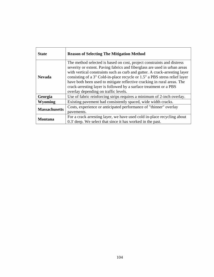
104
State Reason of Selecting The Mitigation Method
Nevada
The method selected is based on cost, project constraints and distress
severity or extent. Paving fabrics and fiberglass are used in urban areas
with vertical constraints such as curb and gutter. A crack-arresting layer
consisting of a 3" Cold-in-place recycle or 1.5" a PBS stress relief layer
have both been used to mitigate reflective cracking in rural areas. The
crack-arresting layer is followed by a surface treatment or a PBS
overlay depending on traffic levels.
Georgia Use of fabric reinforcing strips requires a minimum of 2-inch overlay.
Wyoming Existing pavement had consistently spaced, wide width cracks.
Massachusetts Costs, experience or anticipated performance of "thinner" overlay
pavements.
Montana For a crack arresting layer, we have used cold in-place recycling about
0.3' deep. We select that since it has worked in the past.

105
6- What criteria were used to determine appropriate reflective cracking mitigation
methods?
Table A. 5 Criteria for Selecting an Appropriate RC Mitigation Method
State Visual
survey
Field evaluation/
testing
Traffic
level
Pavement
structure
Illinois Yes Yes Yes Yes
Alaska Yes No No No
Idaho Yes Yes No Yes
Iowa Yes No Yes Yes
West Virginia Yes No No No
Washington Yes No No No
Missouri Yes No No Yes
Utah Yes Yes Yes Yes
Ohio Yes Yes No No
Indiana Yes Yes Yes Yes
Arkansas Yes Yes Yes Yes
Minnesota Yes Yes No No
Nevada Yes No No Yes
Georgia Yes Yes Yes Yes
Wyoming Yes No No No
Massachusetts Yes Yes No Yes
Montana Yes Yes Yes Yes

106
7- Based on field experience, which reflective cracking mitigation method has been
the most successful in your state? (Close-ended)
Table A. 6 The Most Successful Mitigation Method
State The Most Successful RC Technique
Illinois Increased Overlay Thickness
Alaska Paving fabrics/geotextiles
Idaho Reinforced HMA overlay (i.e. geogrids, steel, fiberglass)
Iowa Strata
West Virginia Increased Overlay Thickness
Washington Increased Overlay Thickness
Missouri Increased Overlay Thickness
Utah Other- CIR Interlayer
Ohio Paving fabrics/geotextiles
Indiana Increased Overlay Thickness
Arkansas None
Minnesota SAMI
Nevada Crack Arresting layer
Georgia Crack Arresting layer
Wyoming Increased Overlay Thickness
Massachusetts Other-Milling, SAMI + Thicker Overlay
Montana Crack Arresting layer

107
8- When using the best performing mitigation method, what is the performance
expectation? In other words, how much longer do you expect it to last before
reflective cracks appear? (Open-ended)
Table A. 7 Life Expectation of the Best Performing Mitigation Method
State Life Expectation of RC Mitigation Method
Illinois Hope to delay by a year or 2 and also minimize the severity.
Alaska 4-5 years
Idaho Hope to get 4 to 6 year improvement
Iowa
Timeframe is not defined, but would be a factor in determining the net
cost (added cost of crack mitigation method - maintenance cost savings)
of the method being evaluated.
West
Virginia
So far the most used method has been thicker overlays and the general
rule of one year per an inch HMA seems to apply. In some cases though
possibly sooner.
Washington
WSDOT does not have a major problem with reflective cracking. We do
not have documentation available. Our estimate is that the treatments
provide an extra two years of performance.
Missouri Some pavements experienced 10 years plus.
Utah N/A
Ohio
We have used fabrics in only a few situations. It has been used
successfully for the reduction of thermal cracking. We have seen fewer
cracks and less severe cracks after ~5 years of performance.
Indiana increase overlay may delay +/- 1 year per inch of thickness.
Arkansas 3 years
Minnesota 2 years (estimate)
Nevada
Results vary depending on climate, traffic levels, quality of construction
and severity of distresses. Typically, cracks are mitigated or reduced for
5-15 years.
Georgia An additional 2 to 4 years
Wyoming More than 5 years.

108
State Life Expectaion of RC Mitigation Method
Massachusetts
5 years of additional life. Your question shouldn't ask just when the first
crack appears, but the extension in service life. if the crack treatment
servies as a waterproof barrier, there are additional performance
benefits to not permitting the water to enter the pavement structure.
Montana Cold in-place recycling before overlaying probably keeps the reflective
cracking from appearing indefinitely.

109
9- Prior to designing the HMA overlay for a flexible pavement, what pavement tests and measurements are conducted for
designing appropriate reflective cracking mitigation techniques? (Close-ended)
Table A. 8 Tests to Evaluate the Existing Pavement before Overlaying
State Falling weight
deflectometer
Ground
penetrating
radar
Coring Dynamic cone
penetrometer
Visual
survey
Traffic
count/vehicle class
Laboratory
testing
Illinois No No No No Yes Yes No
Alaska Yes No No No Yes Yes No
Idaho Yes Yes Yes No Yes Yes No
Iowa No No No No Yes Yes No
West
Virginia Yes No Yes No Yes No No
Washington No No Yes No Yes No No
Missouri - - - - - - -
Utah Yes No Yes No Yes Yes Yes
Ohio No No No No Yes No No
Indiana Yes No Yes No Yes Yes No
Arkansas Yes No Yes No Yes Yes No

110
State Falling weight
deflectometer
Ground
penetrating
radar
Coring Dynamic cone
penetrometer
Visual
survey
Traffic
count/vehicle class
Laboratory
testing
Minnesota No No No No Yes No Yes- pave
tech van
Nevada No No Yes No Yes Yes No
Georgia No No Yes No Yes Yes No
Wyoming Yes No Yes No Yes No No
Massachuse
tts Yes No Yes No Yes Yes No
Montana No Yes Yes No Yes No No

111
10- What treatment(s) are typically used to prepare the existing flexible pavement before placing the HMA
overlay? (Close-ended)
Table A. 9 Typical Treatments on Flexible Pavements before Placing HMA Overlay
State
Surface repairs
(e.g., crack
sealing,
patching, etc.)
Milling
only
Milling and
replace
wearing
surface (or
inlay)
Hot-in place
recycling and
heater
scarification
Full-depth
reclamation
No
treatment
Others
(please
specify)
Illinois Yes Yes Yes No Yes No No
Alaska No No Yes No No No No
Idaho Yes No Yes No No No No
Iowa Yes Yes Yes No No No
Yes-cold in-
place
recycling
West Virginia Yes No Yes No No No No
Washington No No Yes No No No No
Missouri Yes Yes Yes Yes Yes Yes No
Utah No Yes Yes No Yes No Yes-mill and
CIR

112
State
Surface repairs
(e.g., crack
sealing,
patching, etc.)
Milling
only
Milling and
replace
wearing
surface (or
inlay)
Hot-in place
recycling and
heater
scarification
Full-depth
reclamation
No
treatment
Others
(please
specify)
Ohio No No Yes No No No
Yes- partial
depth repairs
or full depth
depending on
need.
Indiana Yes Yes No No No No No
Arkansas Yes Yes No No No No No
Minnesota Yes No Yes No Yes No Yes-CIR
Nevada Yes No Yes No No No No
Georgia Yes Yes Yes No Yes No No
Wyoming Yes Yes No No Yes No No
Massachusetts Yes Yes Yes No Yes Yes No
Montana Yes Yes No No Yes Yes
Yes-
sometimes
cold-in place
recycling

113
11- For HMA overlay design, do you use a design method/guideline or simply use a minimum thickness?
(Typical/minimum thickness description: e.g., 5 inches of HMA – 2 inches of 12.5 mm PG 76-22 over PG 76-22 over 3
inches of 19 mm PG 64-22) (Close-ended)
Table A. 10 Overlay Design Method
State Overlay Design Method
Illinois AASHTO-based procedure or Asphalt Institute
Alaska Mechanistic Design Method
Idaho Department uses WINFLEX program developed by University of Idaho.
Iowa AASHTO design method
West Virginia Min Thickness based on Traffic, Field Testing, Pavement Condition
Washington Min Thickness, Remove and replace the top lift of top down cracked HMA. Typical depth is 0.15'.
Missouri Min Thickness based on Pavement Condition
Utah Design method/Guideline
Ohio
For our multi-lane divided routes we use deflection based methodology based on the Area method
in the most recent AASHTO Guide. For our two lane-lower volume rural routes we use a standard
1-1/4" to 3-1/2" mill and fill, based on the level of cracking/distress, and what has worked in the
past, as well as traffic levels (ie:experience based)

114
State Overlay Design Method
Indiana DARWin ME, or other version of MEPDG
Arkansas Design method/Guideline
Minnesota Design method/Guideline
Nevada AASHTO-93
Georgia Guideline-Structural Number
Wyoming Are transitioning to DARWin-ME
Massachusetts 1972 AASHTO Pavement Design Method (Modified per DOT research) or 1993 AASHTO
Interim Design Guide
Montana Min Thickness- Based on Traffic and Pavement Condition

115
12- What constitutes criteria for a successful reflective cracking mitigation method?
(in terms of improved performance, percentage reflected cracks, or both);
Example: 50% of the reflective cracks appear after two years. (Open-ended)
Table A. 11 Expectation from an Applied Mitigation Method
State Life Expectation
Illinois N/A
Alaska 50% of the reflective cracks appear after two years
Idaho Double the time between the mitigation section and a control section as
to when reflective cracks reappear.
Iowa No criteria established
West Virginia
We do not really have true established performance criteria at this time.
But looking to develop some. Have started rewriting our HMA specs to
include more in place end result specs for visual distress, surface
irregularities, joint construction, etc.
Washington N/A
Missouri A combination of both. Some treatments have resulted in reduced
frequency of cracking while increasing in severity.
Utah N/A
Ohio We do not currently use a standard mitigation method. But are
evaluating the use of a chip seal interlayer
Indiana No method of measuring success or not.
Arkansas 30% or less in 3 years
Minnesota not a specific target
Nevada Minimal cracking after 5 years
Georgia No objective criteria established currently. Research underway.
Wyoming Less severity (width) of resulting crack and delayed reflection.
Massachusetts 80% of cracks delayed for 5 years.
Montana N/A

116
13- Do you consider life-cycle cost for each mitigation method? (Close-ended)
Table A. 12 Considering Life Cycle Analysis in Selecting the Method or
Treatment
State Life Cycle Cost Analysis
Illinois No
Alaska No
Idaho No
Iowa No
West Virginia No
Washington Yes
Missouri No
Utah Yes
Ohio No
Indiana Yes
Arkansas No
Minnesota No
Nevada yes
Georgia No
Wyoming No
Massachusetts Yes
Montana No

117
14- How much is the unit cost of the method (per lane-mile)? (Open-ended)
Table A. 13 Unite Cost of the Selected Method
State Unit Cost of the selected Method
Illinois N/A
Alaska N/A
Idaho N/A
Iowa N/A
West Virginia
Typical contract cost for two-lane secondary routes on the order of
about $100,000 per lane per mile. For interstate four-lane routes not too
much different, but a little more in some cases due to higher grade of
materials used.
Washington
WSDOT uses $240 K per lane mile. This cost is fully loaded,
preliminary engineer, construction engineering, taxes and
contingencies.
Missouri N/A
Utah N/A
Ohio
Chip seal interlayer is fairly low cost ~$2/sy. Fabrics can be pretty
expensive and would only be used where thermal cracking is pervasive
and controls the time to resurface.
Indiana N/A
Arkansas unknown / highly variable
Minnesota varies
Nevada N/A
Georgia
Pavement reinforcing fabric and 3” PBS--$195,585 per lane mile 2.
1.5” type 3, 2” PBS--$171,165 3. 3” CIR, 2” PBS--$265,307 4. 3” CIR
and Chip Seal--$173,488
Wyoming unknown
Massachusetts N/A
Montana Mill, SAMI & HMA overlay = $115K per lane mile

118
REFERENCES
Amini, F. (2005). Potential Applications of Paving Fabrics to Reduce Reflective
Cracking, (February).
Arif Chowdhury, Joe W. Button, and R. L. L. (2009). Tests of HMA Overlays Using
Geosynthetics to Reduce Reflection Cracking, 7(2).
Asphalt rubber usage guide. (2003)., (January).
Baek, J., Al-Qadi, I. L., Xie, W., & Buttlar, W. G. (2008). In Situ Assessment of
Interlayer Systems to Abate Reflective Cracking in Hot-Mix Asphalt Overlays.
Transportation Research Record: Journal of the Transportation Research Board,
2084(-1), 104–113. doi:10.3141/2084-12
Beach, P. (2005). Experimental Project Status Report, 12–15.
Bennert, T. (2009). A Rational Approach to the Prediction of Reflective Cracking in
Bituminous Overlays for Concrete Pavements.
Bennert, T., & Maher, A. (2007). Evaluation of Current State of Flexible Overlay Design
for Rigid and Composite Pavements in the United States. Transportation
Research Record, 1991(1), 97–108. doi:10.3141/1991-12
Bennert, T., Worden, M., & Turo, M. (2009). Field and Laboratory Forensic Analysis of
Reflective Cracking on Massachusetts Interstate 495. Transportation Research
Record: Journal of the Transportation Research Board, 2126(-1), 27–38.
doi:10.3141/2126-04
Blankenship, P., Iker, N., & Drbohlav, J. (2004). Interlayer and Design Considerations to
Retard Reflective Cracking. Transportation Research Record, 1896(1), 177–186.
doi:10.3141/1896-18
Carmichael, R. F. (FRANK)III A. M. L. M. (1988). Synthesis and Literature Review of
Nonwoven Paving Fabrics, (99).
Chen, D., Won, M., Scullion, T., & Bilyeu, J. (n.d.). Minimizing Reflective Cracking
With Applications of the Rolling Dynamic Deflectometer and Overlay Tester, 3–
14.
Chen, Y. (2012). EVALUATION OF ASPHALT RUBBER MEMBRANCE
INTERLAYER ( ARMI ) USING THE UNIVERSITY OF FLORIDA ’ S
COMPOSITE SYSTEM INTERFACE CRACKING ( CSIC ) TEST, (May).
Cleveland, G. S., Button, J. W., & Lytton, R. L. (2002). GEOSYNTHETICS IN
FLEXIBLE AND RIGID PAVEMENT, 7(2).
Dempsey, B. J. (2006). INTERLAYER STRESS ABSORBING COMPOSITE ( ISAC )
FOR MITIGATING REFLECTION CRACKING IN ASPHALT CONCRETE,
(94).
DeVille, B. (2006). Decision Trees for Business Intelligence and Data Mining: Using
SAS Enterprise Miner. SAS Institute Inc. Cary, NC, USA
119
Fujie Zhou, Sheng Hu, Xiaodi Hu, and T. S. (2009). FHWA / TX-09 / 0-5123-3
MECHANISTIC-EMPIRICAL ASPHALT OVERLAY THICKNESS DESIGN
AND ANALYSIS SYSTEM November 2008 Resubmitted : February 2009
Resubmitted : July 2009 Published : October 2009 Fujie Zhou , Sheng Hu , Xiaodi
Hu , and Tom Scullion Report 0-512, 7(2).
Gayle, N., & Helen, W. (1988). Polymer Modified Bitumen: Laboratory Evaluation,
Construction Guidelines and Field Experience.
Greene, J. (2012a). State of Florida Department of Transportation Effect of Asphalt
Rubber Membrane Interlayer ( ARMI ) on Instability Rutting and Reflection
Cracking of Asphalt Mixture, (September).
Greene, J. (2012b). State of Florida Department of Transportation Effect of Asphalt
Rubber Membrane Interlayer ( ARMI ) on Instability Rutting and Reflection
Cracking of Asphalt Mixture, (September).
Hicks R, Seeds SB, Peshkin DG. (2000). Selecting a Preventive Maintenance Treatment
for Flexible Pavements, Foundation for Pavement Preservation, McLean.
Johanns, M., & Craig, J. (n.d.). Pavement Maintenance.
Loria, L., Sebaaly, P. E., & Hajj, E. Y. (2008). Long-Term Performance of Reflective
Cracking Mitigation Techniques in Nevada. Transportation Research Record:
Journal of the Transportation Research Board, 2044(-1), 86–95.
doi:10.3141/2044-10
Mixes, D. (2007). CHAPTER 10 THIN MAINTENANCE OVERLAYS, I.
Sholar, G. A., & Moseley, H. L. (2006). Evaluation of Segregation for Top-Down,
(October).
State of Florida Department of Transportation Asphalt Rubber Membrane Interlayer
( ARMI ). (2011)., (February).
State of Florida Department of Transportation Crack Relief. (2012)., (August).
Symons, M., & Herrin, S. (n.d.). Technical Guide AAPTP 05-04 Techniques for
Mitigation of Reflective Cracks, (217).
Thompson, M. (2008). ROAD REFLECTIVE CRACKING SYSTEM UNDER COLD
CLIMATIC CONDITIONS , EVALUATION AND STUDY OF THE FIBER-
REINFORCED EMULSION MEMBRANE Martin Thompson Midland Asphalt
Materials Inc . International Symposium on Asphalt Emulsion Technology ,
ISAET, (September), 1–20.
Von Quintus, H. L., Mallela, J., Lytton, R. (2003). TECHNIQUES FOR MITIGATION
OF REFLECTIVE CRACKS. FAA WORLDWIDE AIRPORT TECHNOLOGY
TRANSFER CONFERENCE, (April 2010).
Wang, K.; Hu, J.; Ge, Z. (2008). Material Thermal Input for Iowa Materials.
Way, G. B. (1990). Flagstaff I-40 Asphalt Rubber Overlay Project Nine Years of Success.
Woo, W. J., Ofori-abebresse, E., Chowdhury, A., Kraus, Z., Martin, A. E., & Glover, C. J.
(2007). Polymer Modified Asphalt Durability in Pavements, 7(2).