Embed Size (px)
Citation preview

Abstract—In the presented paper the realization of an artificial functional unit of muscular hydrostat inspired by the octopus is shown. The octopus has been chosen because it shows high manipulation capabilities and dexterity without a skeletal support, thus it is a good example of Embodied Intelligence. Inspiration from Nature concerns the features that are interesting from a robotic point of view for the development of an artificial muscular hydrostat: in particular actuators arrangement and their antagonistic mechanism. The main focus was on the two key elements of the unit: soft actuators and support structure. Shape memory alloys (SMA) has been chosen for actuation technology, whereas the support structure is a braided sleeve, that provides spatial continuity to the action of the actuators. Two contiguous units have been built and tested in water. Capabilities of shortening, elongation and bending have been observed and their performances evaluated. A maximum elongation of 43% has been recorded from shortened to elongated condition, with a diameter variation of 25%, finding a good match with the expected results from the support structure models. Relative angle between extremities has been measured during bending in two conditions and their efficiency has been compared.
I. INTRODUCTION OST animals provide evidence of the need for
soft/compliant body parts, in order to achieve an effective motor behaviour in our world. Extreme examples are completely soft animals, like worms and caterpillars [1], or molluscs. Among molluscs, the octopus represents a very interesting model for robotics because, differently from warms and caterpillars, it shows manipulation capabilities, in addition to locomotion. The octopus has eight arms which can twist, change length, and bend in all directions at any point along the length. Despite the lack of rigid skeletal support, the octopus can vary the arm stiffness to perform several movements and, in general, to apply forces on the environment [2].
Because of these features, the octopus arm has been sometimes a source of inspiration in robotics, basically for the development of hyper-redundant robot manipulators [3].
The control of this large number of degrees of freedom in
Manuscript received January 31, 2012. This work was supported by the European Commission in the ICT-FET OCTOPUS Integrating Project, under contract n. 231608.
Maurizio Follador, Matteo Cianchetti, and Cecilia Laschi are with Scuola Superiore Sant’Anna, The BioRobotics Institute, Viale Rinaldo Piaggio, 34 56025 - Pontedera (PI), Italy - {maurizio.follador; matteo.cianchetti; cecilia.laschi}@sssup.it
Maurizio Follador is also with The Center for Micro-BioRobotics@SSSA, Istituto Italiano di Tecnologia (IIT), Polo Sant'Anna Valdera, Viale Rinaldo Piaggio, 34 56025 - Pontedera (PI), Italy – [email protected]
the octopus is highly distributed and it is simplified by the use of stereotyped movements. Moreover, the morphology of the arms and the mechanical characteristics of their tissues are such that the interaction with the environment, namely water, is exploited to simplify control. The octopus represents a biological demonstration of how effective behaviour in the real world is tightly related to the morphology of the body. It stands as a good example of Embodied Intelligence [4].
The key principle explaining the performance of the octopus arm is the muscular hydrostat [5], a muscular structure with muscles arranged on longitudinal and transverse planes, which can deform and vary its stiffness with contractions [6]. Copying the principles of the muscular hydrostat is leading to the design of an artificial muscular hydrostat [7] and to the development of robotic octopus prototypes [8],[9], which represent a new class of soft robots and technologies [10],[11].
Traditional robots are mostly built on rigid structures and the robotics technologies, techniques and theories developed in the last 50 years heavily rely on this basic assumption [12]. In new real-world applications of service robotics, the stiffness of robot links may limit their ability to interact with their environment, especially encountering difficulties when operating in unstructured or highly congested situations. Soft robotics [13], as a new emerging field in robotics, goes beyond the traditional concept of rigid bodies, representing a disruptive challenge for robotics technologies and for the design of adaptive structures. Soft, elastic and deformable systems are key issues for smooth and soft interactions with the physical environment, opening to robots with high dexterous capabilities for a wide range of applications [14].
In this paper we present the development of a completely soft structure inspired to the morphology of the octopus arm muscular hydrostat. In the next section the biological derivation is reported, clarifying the features that are copied from Nature and their importance from an engineering point of view. Then the design of the single unit is introduced together with the materials and the technologies used for the different components. Finally the structure has been assembled and tested in order to assess its performances and the results have been discussed.
II. BIOLOGICAL DERIVATION In the arms of the octopus, muscles are organized into
transverse, longitudinal, and obliquely orientated groups [6],[15], as illustrated in Figure 2. This special muscular
Development of the functional unit of a completely soft octopus-like robotic arm
M. Follador, Member, IEEE, M. Cianchetti, Member, IEEE, and C. Laschi, Member, IEEE
M
The Fourth IEEE RAS/EMBS International Conferenceon Biomedical Robotics and BiomechatronicsRoma, Italy. June 24-27, 2012
978-1-4577-1198-5/12/$26.00 ©2012 IEEE 640
organization forms the structures called muscular hydrostats, whose main property is that their volume remains constant during muscle contractions [2]. The result is that if the diameter of a muscular hydrostat decreases, its length increases, and vice versa. The relation between them is:
20
)5.0( DVL
(1)
where D is the diameter, L is the length and V0 is the constant volume of the cylinder. The relative variation of D and L, expressed in percentage, is independent from the numerical values of the geometry of the arm and it is given by the following relation:
112
00
DD
LL (2)
where L0 and D0 are the initial length and diameter, respectively. When L0 is greater than D0, then small reductions of the diameter correspond to large increases of the length. In the geometry of the octopus arm, we always have 100 DL and typically 0100 DL .
Elongation of a portion of the arm is thus obtained by contraction of the transverse muscles, that decrease the arm cross-sectional area.
Shortening results from the opposite activation: the contraction of the longitudinal muscles. Torsion of the arm is obtained by the contraction of the oblique muscles. Bending in every direction can be obtained by the contraction of longitudinal muscles on the desired side of the arm and, simultaneously, by the contraction of transverse muscles in order to resist the longitudinal compression forces caused by contraction of the longitudinal muscles [2]. The arrangement of the transverse and longitudinal muscles allows a reciprocal antagonistic action, enabling the possibility to vary locally the stiffness of the arm by contracting both kind of muscles. This confers to the octopus the capability to use its muscular system as a modifiable skeleton, essential for the transformation of force into movement.
III. DESIGN OF THE UNIT The basic principles of the smart muscle arrangement of
the octopus arm have been used for the design of a robot arm that has to work in water. The key principle of the biological
muscular hydrostat taken as inspiration is the arrangement of longitudinal and transverse muscles, on normal planes. The main advantage is that this smart muscular structure simplifies some of the movements of the octopus arm and reduces the complexity of the required mechanisms and actuators, as some of the muscle deformations are in fact passive (i.e. the elongation of longitudinal muscles by transverse contractions).
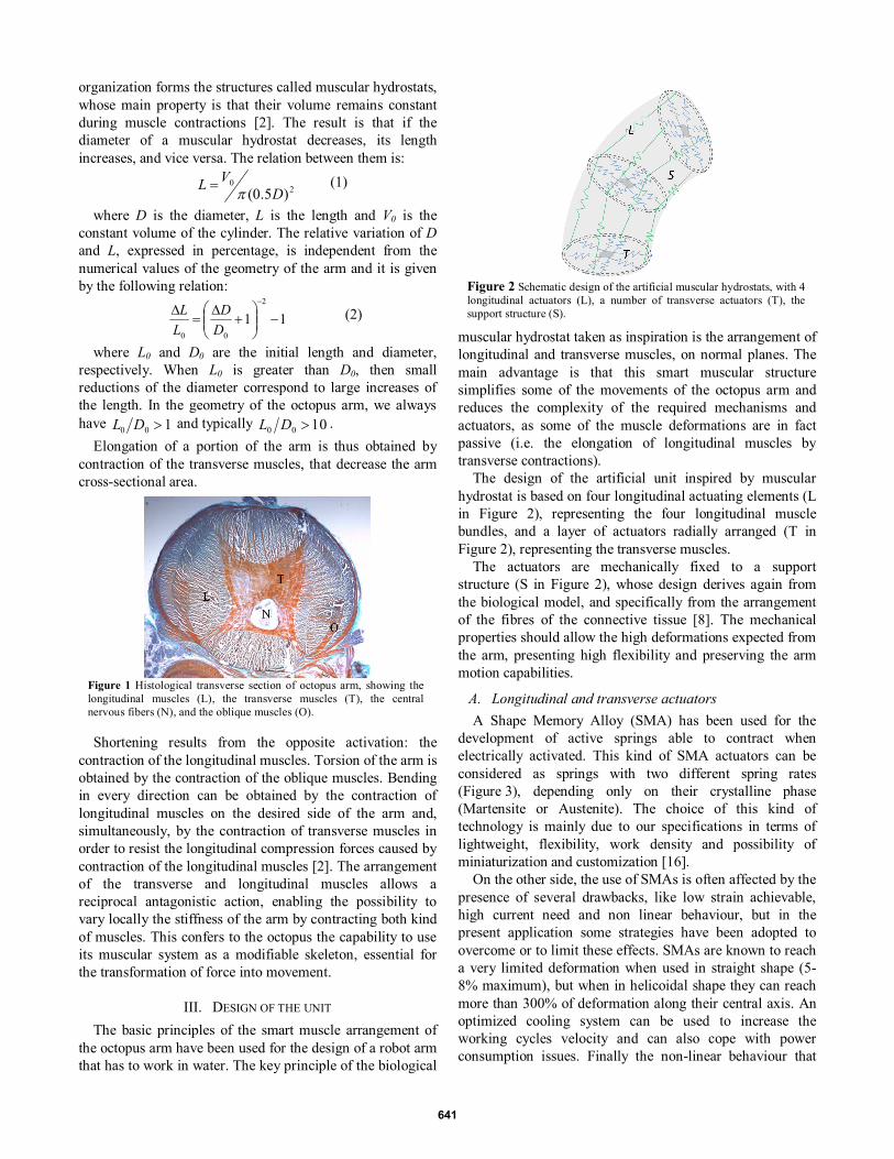
The design of the artificial unit inspired by muscular hydrostat is based on four longitudinal actuating elements (L in Figure 2), representing the four longitudinal muscle bundles, and a layer of actuators radially arranged (T in Figure 2), representing the transverse muscles.
The actuators are mechanically fixed to a support structure (S in Figure 2), whose design derives again from the biological model, and specifically from the arrangement of the fibres of the connective tissue [8]. The mechanical properties should allow the high deformations expected from the arm, presenting high flexibility and preserving the arm motion capabilities.
A. Longitudinal and transverse actuators A Shape Memory Alloy (SMA) has been used for the
development of active springs able to contract when electrically activated. This kind of SMA actuators can be considered as springs with two different spring rates (Figure 3), depending only on their crystalline phase (Martensite or Austenite). The choice of this kind of technology is mainly due to our specifications in terms of lightweight, flexibility, work density and possibility of miniaturization and customization [16].
On the other side, the use of SMAs is often affected by the presence of several drawbacks, like low strain achievable, high current need and non linear behaviour, but in the present application some strategies have been adopted to overcome or to limit these effects. SMAs are known to reach a very limited deformation when used in straight shape (5-8% maximum), but when in helicoidal shape they can reach more than 300% of deformation along their central axis. An optimized cooling system can be used to increase the working cycles velocity and can also cope with power consumption issues. Finally the non-linear behaviour that
Figure 1 Histological transverse section of octopus arm, showing the longitudinal muscles (L), the transverse muscles (T), the central nervous fibers (N), and the oblique muscles (O).
Figure 2 Schematic design of the artificial muscular hydrostats, with 4 longitudinal actuators (L), a number of transverse actuators (T), the support structure (S).
641

lead to low controllability issues have been solved using an all-nothing activation strategy (intermediate situation where the two phases coexist is neglected) and exploiting the agonistic-antagonistic mechanism the longitudinal and the transverse springs.
The design of the SMA helical springs has four parameters to consider: • NiTi Alloy mechanical properties • Wire diameter • Average spring diameter • Number of coils
Classical spring theory and the mechanical properties of the material have been used for the design of springs with the desired performances.
The mechanical requirements of the springs are mainly based on the optimization of the movement performances of the unit, thus the design has to take into account that the active springs have to be able to deform both the support structure and the inactive spring (the antagonistic spring). It means that when the transverse springs are activated they elongate the support structure and the longitudinal springs and vice versa when the longitudinal springs are activated.
The material used for the actuators is a commercial available alloy called SmartFlex® (SAES getters group, Milano, Italy).
B. Support structure One of the main consequences due to the use of SMA
springs as actuators is the discretization of the system respect to the continuity that the Nature can implement. Nature can count on thousands of versatile, little and efficient contracting elements (sarcomeres) that macroscopically form a continuous structure (muscle fibres), but in our case the number of artificial actuators has to be held down. Energy issues, available space and handling problems have to be faced when the number of SMA springs is high. The most evident effect is the appearance of the barreling effect (Figure 4) both in longitudinal (due to the distance among the sections) and in transverse manner (due to the very local action of the SMA springs on whatever soft material used to embed them). These considerations (together with the total absence of internal rigid links) make crucial the development of a suitable interface between the actuators. The interface should be represented by a structure with intermediate elastic properties where the actuators
could be mechanically fixed on. In the use of SMA, in particular, this interface covers a key role in the success of the motion mechanism. On the other side the mechanical properties of such a structure should not interfere with the passive features of the arm that means it has to present high flexibility and preserve motion capability.
The chosen robot arm support structure consists of a braided sleeve. This not only provides a perfect mechanical support and containment functions, but it generates passive elongation by diameter reduction. The design of the sleeve is based on a study of how the geometry and the material influence the passive properties of the entire structure.
From an analytical point of view these kind of structures have been widely investigated since they are often used for McKibben actuators, for its capability to shorten when the diameter is increased [17][18]. In that case, in fact, when an air chamber placed inside the braided sleeve is inflated, it causes a shortening of the structure that can be modulated by the air volume and pressure. On contrary, in this study, both elongation and shortening properties will be exploited. Moreover it shows another advantage: during the squeezing, the cylindrical shape is generally maintained (even applying punctual force to reduce the diameter), that allows to use a few actuators without affecting the geometrical shape.
Available analytical models (for cylindrical braids) usually used to describe the quantitative behaviour of the braid are based on the fact that braided fibres cannot be stretched (Lf is constant). Moreover the symmetry of the
structure allows the study of one single cell fibre without loss of generality. In this way the flat development of this structure can be approximated to a rectangle and the model is reduced to a simple trigonometric problem where the vertical length of a single cell (L) of the braid can be expressed as:
cosfLL (3)
where Lf is the braid yarn length and theta is the braid angle (the angle that the yarns form respect to the longitudinal axis). Other two important parameters are the diameter (D) and the volume (V) that depend on the size of the considered structure:
sin2 fBL
D (4)
ALDV 42
(5)
Figure 3 Example of stress-strain curve for martensite and austenite phases.
Figure 4 Barreling effect caused by local forces (red arrows) on a soft deformable material in a cylindrical shape.
642

where A and B are the number of unit cells in the vertical and circumferential direction respectively.
The previous equations are applicable in the case of cylindrical braids, the present work is investigating the single unit of an arm inspired by the octopus structure and one important thing to replicate is the conical shape. This means that the model should be modified in order to take into account the variation of the diameter along the structure, but in this paper a very short portion of braid is considered and we can assume a behaviour very similar to the cylindrical geometry.
This model can predict the geometrical and ideal behaviour of the structure, but it does not take into account several parameters of the physics of the problem and for example it cannot describe the barreling effect. To face this issue we developed a FEM simulation that predicts the elongation performances more precisely and giving accurate information about the required forces and the longitudinal propagation of the radial compression.
The focus of the simulation is to describe the effect of the local deformation that propagates along the arm for a limited space. This realistic scenario considers a complex geometry, as well as the interaction among the fibres. To this purpose a FE analysis software (MARC Mentat 2010, MSC Software) has been used to reproduce the physics of the system, considering both geometric quantities (like type of braiding, sinusoidal fibre path, fibre thickness and cross section) and material properties (like Young modulus, Poisson coefficient
and friction). A small part of the braided sleeve has been virtually reconstructed and all the mechanical properties of the material have been set. The geometry shown in figure x has been used for the simulation. It has 48 fibres (24 right-handed and 24 left-handed), the same braiding architecture and octopus arm proportions.
For the FEM simulation samples of 60 mm have been virtually replicated (Figure 5). Four forces (simulating the
effect of the SMA springs) have been applied radially and the resulting elongation has been evaluated.
In order to try to describe more in detail the barreling effect and quantitatively characterize the phenomenon, the FEM model and experimental results on a real braid have been compared (see TABLE I). Quantitatively the FEM model can predict the elongation capabilities of the real braid with an error less than 3%. The local reduction of the diameter causes an elongation of the structure in a way that is consistent with the FEM results: the circular shape is maintained and the diameter reduction has a maximum elongation effect at the centre of the structure and decreases upwards and downwards (Figure 6). This effect is important to set a distance among the transverse modules that guarantees an overlapping action among them minimizing the barreling effect.
Moreover the FEM simulations have been used to estimate the force necessary to obtain the desired deformations and thus for designing the SMA springs.
IV. FABRICATION OF THE UNIT The transverse modules composed by eight springs and
held by a ring together with the electric wires, are inserted in the conical braid and fixed to its yarns. Once put in place inside the braid, each SMA spring is tied to a yarn crossing in order to create a stable connection without limiting the relative rotation of the yarns during the deformation of the braid.
The longitudinal springs are arranged along the structure, each one starting from one transverse springs module till the next one. They are placed close to the fibres braid to maximize the bending capability. To prevent the possibility that longitudinal springs interfere with the transverse springs during contractions, some loops of nylon yarn are used to maintain the springs close to the braid. Even if the loops are not the only solution for this issue and for sure not the most elegant, they guarantee that cables remain in this delocalized
TABLE I ELONGATION RESULTS OBTAINED FROM THE COMPARISON BETWEEN FEM
SIMULATION AND EXPERIMENTAL TESTS ON PET BRAID WITH 0.4 MM DIAMETER FIBRES WHEN FOUR RADIAL FORCES ARE APPLIED.
FEM model experimental L1 31.5 mm 31.5±1 mm L2 34.5 mm 35.5±1 mm
Figure 6 Example of braid sample subjected to barreling effect: the FEM model is able to envisage the limited longitudinal propagation of the diameter reduction.
Figure 7 Fabrication process: the braid (left) is used as a supporting structure where the transverse springs have been fixed (centre); the longitudinal springs have been then connected at the same insertion points.
Figure 5 Sample of braided sleeve virtually reconstructed for Finite Element Analysis.
643

position respect to the springs and present a very low friction.
The structure obtained with the fabrication process described above represents the single unit of an arm and it is composed by two transverse modules and one longitudinal module (Figure 7). The distance between the two transverse modules is set in according to the results obtained in the Finite Elements Analysis.
V. RESULTS AND DISCUSSION The structure obtained with the fabrication process
described above is shown in Figure 8 and represents the functional unit of completely soft arm inspired by the octopus functional morphology. Actually the structure in the figure is composed by two units: three transverse modules and two longitudinal modules. This choice led to a better evaluation of the performances of the structure. In this way
the central transverse module is bordered between two consecutive transverse modules and the continuity of the elongating mechanism is easier to assess. The most important thing is to avoid the barreling effect that limits the elongation capacity of the braided structure. Moreover, the two contiguous longitudinal modules allow the evaluation of the single modules and of eventual cross interferences between them. These effects (and in general every deformation applied to the braid) have to be taken into serious consideration since the structure is continuous and the effects propagates longitudinally and transversally.
The unit has been tested in water and with activation current on the order of 1.2 A (of course the power consumption depends on the resistance of the springs that in turn depends on the number and dimension of the coils). The performances of the units are reported in TABLE II. The capabilities of the structure have been tested several times to identify eventual appearance of fatigue phenomena and the values reported refer to the average of the data obtained.
A. Elongation and shortening The elongation and shortening mechanism has been
activated in sequence and they have been numerically evaluated. Maximum elongation can be obtained in 3 s and maximum shortening takes about 2 s that means a longitudinal deformation speed of 6 mm/s and 9 mm/s respectively.
The deformations are very well aligned with the expected results. In Figure 9 the curve describing the behaviour of the braid is shown (derived from equations reported in section II) and the three dots on the plot indicate the experimental performances of the structure. The second curve shows the performances of an isovolumetric structure that has the same initial length and diameter (49.6 mm and 26.4 mm respectively). From the comparison between the two curves it is possible to see that the braided structure presents the same trend (elongation when the diameter is decreased and diameter increase when shortened), but following two different laws. From an engineering point of view it is not an issue a priori, but in order to take advantage from the mechanism it is preferable that a relatively small activation
Figure 8 Elongation and shortening mechanism of the braid (the vertical black line on the bottom right is 10 mm long).
TABLE II PERFORMANCES OF THE UNITS
LENGTH at rest 49.6 mm at max elongation 61.2 mm at max shortening 43.3 mm
elongation percentage 41.3% DIAMETER at rest 26.4 mm
at max elongation 21.2 mm at max shortening 28.3 mm
diameter reduction percentage 25.1% ELONGATION time 3 s
speed 6 mm/s SHORTENING time 2 s
speed 9 mm/s BENDING curvature radius w/o transverse
SMA 54 mm
with transverse SMA 42 mm
angle w/o transverse SMA 43 deg
with transverse SMA 64 deg
time w/o transverse SMA 1.8 s
with transverse SMA 2.2 s
speed w/o transverse SMA 23.9 deg/s
with transverse SMA 29 deg/s
Figure 9 Comparison between the behaviour of an isovulemtric structure (black) and the braid (gray): in the case of the braid angle under investigation (solid line) the elongation amplification is always below the isvolumetric structure, but with a different braid angle (dashed line) it is possible to obtain better results; dots show the experimental results in shortening and elongation.
644
of the transverse actuators would lead to a large elongation of the structure. Figure 9 shows that the isovolumetric structure behaves better than the braid, but not in every conditions. The behaviour of the braid heavily depends on the braid angle. The initial braid angle of the structure used for the demonstrator is 50 deg, but if this angle is increased it can improve the elongation performances. As an example in Figure 9 another curve is shown that demonstrates this: if the initial braid angle is increased till 60 deg the performances of the structure becomes better than the isovolumetric for a fixed range between 0 and 12% (the braid curve lies above the isovolumetric one). This result is very important for the performances of the unit and dictates the behaviour of the entire arm.
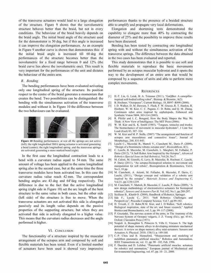
B. Bending The bending performances have been evaluated activating
only one longitudinal spring of the structure. Its position respect to the centre of the braid generates a momentum that creates the bend. Two possibilities can be distinguished: the bending with the simultaneous activation of the transverse modules and without it. In Figure 10 the difference between the two behaviours can be evaluated.
In the first case the longitudinal contraction leads to a
bend with a curvature radius equal to 54 mm. The same amount of voltage has been applied to the same longitudinal spring also in the second case, but at the same time the three transverse modules have been activated too. In this case the curvature radius value reach 42 mm. The correspondent bending angles are 43 deg and 64°deg respectively. The difference is due to the fact that the active longitudinal spring (right side in Figure 10) set the arc length of the bent structure to the same value in both cases, but the other side (left side) of the structure is free to move. When the transverse actuators are not activated this side is elongated passively and its length value depends on the passive properties of the supporting structure, but when they are activated that side is actively elongated to a higher value. This means that the curvature radius decreases and the angle performed is higher.
VI. CONCLUSION The functionality of a structure inspired by the muscular
arrangement of the octopus arm and composed by soft and flexible materials has been tested. Even if a limited number of actuators have been used it showed very impressive
performances thanks to the presence of a braided structure able to amplify and propagate very local deformations.
Elongation and shortening tests demonstrated the capability to elongate more than 40% by contracting the diameter of 25% and the possibility to improve these results have been discussed.
Bending has been tested by contracting one longitudinal spring with and without the simultaneous activation of the transverse springs. The difference between the data obtained in the two cases has been evaluated and reported.
This study demonstrates that it is possible to use soft and flexible materials to reproduce the basic movements performed by an octopus muscular hydrostat and it opens the way to the development of an entire arm that would be composed by a sequence of units and able to perform more complex movements.
REFERENCES [1] H.-T. Lin, G. Leisk, B. A. Trimmer (2011), “GoQBot: A caterpillar-
inspired soft-bodied rolling robot”, Bioinsp. & Biomim., 6(2). [2] B. Hochner, “Octopuses”, Current Biology, 18, R897–R898 (2008). [3] I. D. Walker, D. M. Dawson, T. Flash, F. W. Grasso, R. T. Hanlon, B.
Hochner, W. M. Kier, C. C. Pagano, C. D. Rahn, and Q. M. Zhang, Continuum robot arms inspired by cephalopods. Enhanced and Synthetic Vision 5804, 303-314 (2005).
[4] R. Pfeifer and J. C. Bongard, How the Body Shapes the Way We Think: A New View of Intelligence. The MIT Press (2006).
[5] W. M. Kier and K. K. Smith (1985), “Tongues, tentacles and trunks: The biomechanics of movement in muscular-hydrostats”, J Linn Soc Lond (Zool) 83, 307–324.
[6] W. M. Kier and M. P. Stella, (2007) “The arrangement and function of octopus arm musculature and connective tissue”, Journal of Morphology, 268, 831-843.
[7] Laschi C., Mazzolai B., Mattoli V., Cianchetti M., Dario P. (2009), “Design of a biomimetic robotic octopus arm”, Bioins&Biom, 4(1).
[8] C. Laschi, B. Mazzolai, M. Cianchetti, L. Margheri, M. Follador, P. Dario (2012), “A Soft Robot Arm Inspired by the Octopus”, Advanced Robotics (Special Issue on Soft Robotics), Vol.26, No.7.
[9] M. Calisti, M. Giorelli, G. Levy, B. Mazzolai, B. Hochner, C. Laschi, P. Dario (2011), “An octopus-bioinspired solution to movement and manipulation for soft robots”, Bioinspiration & Biomimetics, Vol.6, No.3, 10 pp.
[10] M. Cianchetti, A. Arienti, M. Follador, B. Mazzolai, P. Dario, C. Laschi, (2011), “Design concept and validation of a robotic arm inspired by the octopus”, Materials Science and Engineering C, Vol.31, pp.1230-1239.
[11] M. Cianchetti, V. Mattoli, B. Mazzolai, C. Laschi, P. Dario (2009), “A new design methodology of electrostrictive actuators for bioinspired robotics”, Sensors and Actuators Part B, Vol.142, No.1, pp.288-297.
[12] Siciliano B., Khatib O. (2008), Handbook of Robotics, Springer. [13] Iida F., Laschi C., 2011. “Soft Robotics: Challenges and
Perspectives”, Procedia Computer Science, Vol.7, pp.99-102. [14] D. Trivedi, C. D. Rahn,W.M. Kier, and I. D.Walker, “Soft robotics:
Biological inspiration, state of the art, and future research,” Applied Bionics and Biomechanics, vol. 5, pp. 99–117 (2008).
[15] P. Graziadei, The nervous system of the arms, in The Anatomy of the Nervous System of Octopus vulgaris, J. Z. Young (Ed.), pp. 45-61, Oxford: Clarendon Press (1971)
[16] Nespoli A, Besseghini S, Pittaccio S, Villa E, Viscuso S. The high potential of shape memory alloys in developing miniature mechanical devices: A review on shape memory alloy mini-actuators. Sensors and Actuators A: Physical. 2010; 158(1): p. 149-160.
[17] C.-P. Chou and B. Hannaford, “Measurement and modeling of mckibben pneumatic artificial muscles,” Robotics and Automation, IEEE Transactions on, vol. 12, pp. 90 –102, Feb. 1996.
[18] F. Daerden and D. Lefeber, “Pneumatic artificial muscles: actuators for robotics and automation,” European journal of Mechanical and Environmental Engineering, vol. 47, pp. 10– 21, 2000.
Figure 10 Bending performances: at rest all the springs are not active (left); the right longitudinal SMA spring actuator is activated generating a bend (centre); the right longitudinal spring and the transverse springs are activated generating a more marked bend (right).
645