Embed Size (px)
Citation preview

Development of the Aquarius Antenna Deployment Mechanisms and Spring/Damper Actuator
Joel A Johnson*
Abstract
The Aquarius Instrument’s large radar reflector dish needed to be stowed for launch, and then deployed on-orbit. The Deployment Subsystem consisted of a cantilevered boom structure and two single-axis hinge mechanisms to accurately deploy and position the reflector dish relative to the radar feed horns. The cantilevered design demanded high stiffness and accuracy from the deployment mechanism at the root of the boom. A preload-generating end-of-travel latch was also required. To largely eliminate the need for control systems, each deployment mechanism was actuated by a passive spring motor with viscous-fluid damping. Tough requirements and adaptation of a heritage actuator to the new application resulted in numerous challenges. Fabrication, assembly, and testing encountered additional problems, though ultimately the system was demonstrated very successfully. This paper revisits the development to highlight which design concepts worked and the many important lessons learned.
Introduction
Aquarius ProjectAquarius is the primary, NASA-funded instrument aboard SAC-D, a service platform designed, built, and operated by the Argentinean Comision Nacional De Actividades Espaciales (CONAE). Launched in 2010 with a 3-year earth-orbiting science mission, Aquarius’s primary objective is to map sea-surface salinity to better understand the interactions between the global water cycle, ocean circulation, and climate (salinity affects seawater density, which governs ocean circulation). Aquarius’s sensitive L-band radiometers measure ocean brightness temperature while a scatterometer corrects for ocean roughness effects. The channels share a 2.5 m x 2.8 m composite Reflector cantilevered from the Instrument Primary Structure.
The Reflector and support Boom must be folded to fit within the 3m fairing of a Delta II (Fig. 1). The Reflector pivots about a single-axis hinge-line between it and the Boom, performed by the Upper Deployment Mechanism (UDM). Similarly, the 2 m long Boom pivots at its root via the Lower Deployment Mechanism (LDM). Once stowed, the Reflector is restrained against the Primary Structure via two pyrotechnic Separation Nuts. Upon reaching orbit, deployment occurs in two stages to prevent the Reflector from dragging across the launch restraints (Fig 1). Staging is provided by a pyrotechnic Pin Puller at the LDM, which carries no launch loads. Initial separation of the Reflector is assisted by Kick-off Springs. At the end of its deployment, each Deployment Mechanism latches into final position.
Figure 1. SAC-D Launch Configuration and Aquarius Deployment Sequence
* Jet Propulsion Laboratory, California Institute of Technology, Pasadena, CA
Proceedings of the 39th Aerospace Mechanisms Symposium, NASA Marshall Space Flight Center, May 7-9, 2008.
Pin Puller firing initiates LDM
Deployment and Latching
STOWED
Reflector
Sep Nut firing initiates
UDM Deployment and Latching
UDM
SAC-D
LDM
Feed Horns BoomAquarius
DEPLOYED
235

Together, the Deployment Mechanisms and the Boom comprise the Deployment Subsystem. The overall concept had been accepted at PDR, with actuator selection being an important aspect of the design. “Passive” constant-torque spring motors [1], rate-limited with viscous-fluid rotary dampers, had been chosen to eliminate the need for motor control electronics [2]. JPL’s Spring/Damper Actuator had heritage from Mariner, Viking, Galileo, NSCAT and other missions, but hadn’t been flown in over a decade [3].
The author was tasked with developing the Deployment Mechanisms from this post-PDR level, to overseeing delivery of a single protoflight Mechanism/Boom assembly. The work was carried out at the Jet Propulsion Laboratory, California Institute of Technology, under a contract with the National Aeronautics and Space Administration. The ensuing phases of Design, Fabrication, Assembly, and Test all came with their unique set of challenges, successes, failures, and lessons learned.
Design
RequirementsThe requirements that significantly drove design were as follows [4]:
1. The 1st mode of the deployed Reflector shall be greater than 2 Hz (originally 3 Hz)
2. The Reflector I/F shall be positioned relative to the Primary Structure I/F in the nominal deployed location within the following tolerances: (Reflector pointing alignment)
a. As-delivered: ± 0.1 degree, ± 0.25 mm b. Deployment repeatability: ± 0.05 degree, ± 1 mm c. Mechanical jitter: ± 0.005 degree, ± 0.25 mm
3. Temperature requirements: (Protoflight/design temps) a. UDM Bearings: -75/+45°C Op, -95/+25°C NonOp b. Damper: -5/+45°C Op, -50/+60°C NonOp
Requirements 1 and 2c meant that the deployed system needed to be extremely rigid. The rotational inertia of the deployed Boom/UDM/Reflector about the LDM was approximately 200 kg*m
2. An LDM
rotational stiffness of about 340,000 N*m/rad (allocation) would be necessary to meet the original 3 Hz requirement. At the same time, the system was tightly mass constrained. This presented a significant challenge, taking months of iteration and optimization to try to develop an acceptable Hinge/Latch design. When it started looking like it might not be possible, the Project relaxed the requirement to 2 Hz with surprisingly little resistance. The lesson learned was that before spending too much time trying to meet a requirement, find out how rigid (!) it is.
Lower/Upper Deployment MechanismsEach Deployment Mechanism was comprised of the Hinge (Axle/Clevis/Bearings), the Latch, the Spring/Damper Actuator, the Cable Spool, and Telemetry Switches (Fig. 2). The LDM also included a Pin Puller for staging.
BoomLower End
Fitting
DEPLOYEDSTOWEDSpring/Damper
Actuator
Figure 2. Lower Deployment Mechanism (LDM)
Axle
Clevis
PinPuller
CableSpool
Telemetry Switches
Latch Assy
236
Hingenge consisted of an Axle supported on bearings mounted in a structure called the Clevis (Fig. 3).
he PDR design consisted of a hinge-line created by two angular contact bearings preloaded across the
he use of duplex pairs meant the necessary stiffness and load capacity could be achieved in a bearing
he philosophy of minimizing interfaces was used throughout the design. This became especially
The HiThe Spring/Damper deployed the Axle approximately 60 degrees where it hit a Hardstop and a Latch engaged. The force couple between the Bearings and the Hardstop/Latch resisted motion in the deployment direction. Ultimately, the system performance was driven by the stiffness of the structural connection between these two elements, as well as the coupling of this stiffness to the mating structures.
Figure 3. Hinge
Tentire mechanism. It had been noted that thermal differentials within the Hinge would make it difficult to maintain the bearing preload, and it was recommended at PDR to switch to a back-to-back duplexed (DB) pair at one end, and a floating radial bearing at the other. Unfortunately, due to the stiffness and pointing requirements, it became impractical to implement a bearing that floated axially. Instead, duplex pairs were installed at each end. To minimize the over-constraints, face-to-face (DF) pairs were used, and a careful procedure of axial shimming was implemented. Temperature effects also had to be carefully considered.
Twith nearly half the OD, which would be necessary to keep from doubling the drag. As a result, the Hinge was reduced by about 40% in all three dimensions. However, the Hardstop/Latch was maintained at as great a distance from the hinge-line as practical, since latched stiffness would increase as roughly the square of this distance. Effectively tying all these elements together became crucial for high stiffness, resulting in a very compact design. As such, both the Hardstop and the Latch were made as integral with the Hinge as possible to reduce the structural inefficiencies associated with mechanical interfaces.
Timportant when it came to how the Hinge was to be assembled. Parting the Clevis for Axle installation would have resulted in a massive, heavily bolted seam, as well as registration features and special fabrication steps for bearing alignment. Parting the bearing housings would introduce the same issues, as well as uneven bearing support. Instead, the Axle was parted in such a way as to have negligible effect on Hinge stiffness, with none of the other complications (Fig. 3). Radial load on the Stub results in a shear that is carried through the Stub’s press fit with the Axle, and a moment that is supported by the toe-heel reaction from the axial Bearing clamping. It also turned out that the clamping could be athermalized through simple selection of fastener length. The Stub Axle design, though initially viewed as unconventional, was very successful in the end.
Axle (Ti) Clevis (Ti) DF Bearing Pairs
Spring/Damper (52100 Steel)
Shim
Stub (Ti)
Outer Race Clamp/Cover
237

The system design was further optimized through careful consideration of load paths. This resulted in the somewhat “organic” shape of the Axle and how it “flowed” into the Boom. The lower Boom End Fitting contributes significantly to the stiffness of the Axle and was developed integrally.
A slight exception was that a three-point semi-kinematic interface was implemented between the LDM and the Primary Structure to minimize the potential distortions from bolt-up, because it provided the easiest adjustment if ever required, and because it happened to offer the most direct load path into the Primary Structure at the time. While isolating the Hinge from the mounting interface in this fashion had its benefits, it should be noted that it also had the potentially negative effect of “putting up blinders” to design options that spanned the interface. In hindsight, though the semi-kinematic interface mitigated several potential problems, the existing problem of stiffness possibly could have been remedied more quickly and more efficiently had the Primary Structure been modified to help impart stiffness to the Hinge (like was done between the Axle and Boom Fitting). A lesson learned was to not stop engineering upon reaching an interface. To the extent possible, approaching an interface design from both sides may offer better solutions.
The inertia supported by the UDM was only about one-tenth of the LDM’s, dramatically reducing the stiffness needed to meet the frequency requirement. However, to minimize the number of drawings, parts, test configurations, and spares, it was decided to keep the two Mechanisms as similar as possible. Therefore, the UDM was nearly identical to the LDM, except its deployment angle was shifted by about 20 degrees and it was mass-optimized by thinning most cross-sectional areas of the Axle and Clevis.
BearingsEvery aspect of the Mechanism design encountered complications, and the Bearings were no exception. The initial bearing selection was influenced by the availability of some size 107 spindle bearings left over from another project that would expedite an early brassboard model. To maintain alignment, zero-clearance shaft and housing fits were needed to keep the Hinge axis from permanently shifting under the high radial loads experienced during launch and deployment. At the same time, the Hinge had a very large temperature range because thermal control would be considered only as a last resort. The titanium hardware and the 52100 steel bearings therefore faced a large CTE mismatch problem. Consideration also had to be given to the radial temperature gradient, which strongly affects preload in a DF bearing [5]. Further adding to the challenge, schedule didn’t allow for custom-toleranced bearings, nor fabricating the hardware to match the bearings that were available, resulting in an increased tolerance stack-up. Lastly, the bearings would be lubricated with a light grease-plate of Castrol Braycote 601EF, both for simplicity and schedule. At the lower limit of Braycote’s recommended temperature range, the high lubricant viscosity would be the dominant source of drag. Lubricant drag calculation had the largest uncertainty, requiring additional conservatism.
Bearing analysis software [6] was used to evaluate the wide range of worst-case scenarios. Maintaining a line-to-line fit at one temperature extreme would result in excessive interference at the other, leading to unacceptably high ball stresses. Therefore, some amount of clearance had to be accepted. Further complication then derived from the software’s race clamping inputs. Axial clamp force and coefficient of friction determined if the bearing race was constrained radially by the axial clamping. This effected bearing preload as a function of temperature, depending on whether the race could slip and therefore behave as steel, or if the race was constrained and forced to have a CTE closer to that of the titanium it was clamped between. Given the unreliable nature of the inputs (and somewhat questionable accuracy of the calculated effect), clamping was assumed to always work to the detriment of the system. The final result was that bearing preload and stiffness rapidly dropped off at each end of the temperature range. After many iterations and lots of fine tuning, ID and OD fits were established that just barely maintained the necessary preload at the temperature extremes, without excessive drag elsewhere. While the worst-case analysis was extremely conservative, it was seen as prudent to balance the uncertainty associated with significantly modifying the ground-in preload of duplexed bearing pairs through heavy interference fits (over 25 μm on a 62-mm diameter). The bearings were baselined with a “medium preload” for minimum drag, but with so much hinging on them (!) stiffness testing was planned, and “heavy preload” models were procured just in case additional stiffness was needed. The lesson learned was that bearings are complicated items with long lead times, and should be one of the first elements designed.
238

LatchThe Latch proposed at PDR was a hasp design like that used on Magellan, NSCAT, and MER. As the Hinge was being designed, this type of latch was abandoned in favor of a wedging pawl latch (Fig. 4), based on ability to create preload, stiffness, capture range, and form factor. The Pawl began engaging one degree before the Axle reached the Hardstop, eliminating the potential for rebounding and helping to “drive it home”. The Latch Depressor was implemented so that the work of “cocking” the Latch was done in the stowing process, and wouldn’t impede deployment. This also simplified analyses and reduced test cases. The Pawl was actuated by a redundant pair of nested helical compression springs, through a simple linkage. The linkage was near its knuckle point in the stowed position, to minimize force and drag on the Latch Depressor, with a snubber to prevent linkage over-center. By the same linkage, the torque applied to the Pawl increased to a maximum at the nominal latched position. A very detailed analysis was performed to calculate the preload force between the Axle and Hardstop generated by the Latch (Fig. 5), which was needed for maximum stiffness. The design resulted in only a 13% preload variability over a large (0.5 mm) range of capture. The Hardstop and Latch Strikeplates could be shimmed for adjustment of the Axle’s deployed position, and to center the Latch in the middle of its capture range. The design also had to account for disengaging the Latch after a test, requiring tooling to be developed at the same time.
Figure 4. Latch
0
50
100
150
200
250
300
350
400
450
0 2 4 6 8 10 12 14 16 18 20 22 24 26 28 30 32 34
Latch Angle [deg]
Ha
rds
top
Pre
loa
d [
N]
μ=0.1
μ=0.2
μ=0.4
Nominal Latching Range
Nominal Latch Position
Latch Spring Force
STOWEDSnubber
SpringCanister
Pawl Hardstop Latch Depressor
DEPLOYED
Strikeplates
Figure 5. Hardstop Preload due to Latch, for various coefficients of friction
239

Spring/Damper ActuatorImplementing the heritage Spring/Damper also proved to be considerably more complex than initially planned. The first obstacle was thermal control. Viscosity of the Damper’s silicone working fluid was strongly dependent on temperature. After much petitioning, it was finally agreed that the narrow operational temperature band should be actively controlled by the Instrument, while the survival limits could be maintained with mechanical thermostats. Given the high criticality of the Dampers, both redundant heater circuits and redundant thermostats were required. Power resistors were chosen as heaters due to their robustness and simplicity. Finding adequate surface area to mount all the thermal control hardware dramatically altered the exterior of the Actuator from the heritage configuration (Fig. 6).
Roller Pin (VernierPatterns)
SpringArbor
Heritage Actuator
Accumulator
SpringLaminations
Figure 6. Heritage vs. Aquarius Spring/Damper Actuator
Heaters & Thermostats
Because the Spring/Damper had flight heritage, there was extreme resistance to making any changes. The fluid dynamics within the Damper were considered especially sacred, mainly because there weren’t any of the original developers around. This caused problems because design elements such as bearing fits and spring sizings were not scrutinized adequately, as would be found at assembly. Additional weaknesses and design inconsistencies were perceived, but were not allowed to be addressed. Other elements deemed inconsequential to the damping function, such as direction of rotation, o-ring seals, bearing clamps, structural mounting, and output couplings were modified to facilitate assembly and tailored to the Aquarius implementation. Also, the heritage belleville springs used to generate fluid pressure within the Accumulator were no longer available. Substitutes were found that happened to result in a more constant fluid pressure and were a better material choice. A lubricating PTFE coating on the constant-torque Spring Laminations of the Spring Motor was no longer available, either. Qualifying an acceptable substitute would take time, and application of the coating would complicate the fabrication process. After reasonable investigation, the coating was assessed to be ineffective at solving the spring buckling problem for which it had been implemented, and was eliminated from the design.
The Spring/Damper had to be slightly decoupled from the Axle, so that during launch the dynamic motions of the Boom would not be transmitted and result in extremely high loads. A torsionally-compliant Driveshaft (Fig. 7) was designed, which meant the deploying Reflector could behave more like a pendulum. This was aggravated by the Damper having two damping regimes: low damping initially to accommodate kick-off and stimulate first-motion, transitioning into higher damping to slow the deployment and minimize end-of-travel impact. This transition had the potential to incite deployment oscillations. ADAMS software was used to model the deployment dynamics and tune the Driveshaft. This model was later used as a basis for developing the complicated Gravity Off-Load Fixture (GOLF) that would be used to support the Antenna during instrument-level ground deployments.
240

Damper Rotor Driveshaft Damper Housing (Stator)
Spring Arbor
GSE Drive Hex
Hex Drive
Diaphragm Flexure
(Spring mounting Barrel Washer and Nut)
Figure 7. Spring/Damper Driveshaft
The two damping regimes in fact came in very handy. The Spring/Damper had a full stroke of about 100 degrees, while each Mechanism only deployed about 60 degrees. By biasing the deployment more within one damping regime or the other, the total deployment time and behavior could be tuned. To facilitate this adjustment, the Driveshaft was designed with a vernier rotational indexing pattern between the Axle’s hex drive and the Damper Arbor’s 22.5-degree bolt pattern (Figs. 6,7). The resulting 7.5-degree increment (3*22.5 – 60 = 7.5) allowed the room-temperature deployment time to be systematically adjusted from about 10 s to over a minute in ~10-s steps. This was finer resolution than practical for a splined shaft, and much easier to fabricate. The Driveshaft was also designed to account for misalignment between the Spring/Damper and the Axle. The diaphragm flexure accommodated up to 0.5 mm lateral / 0.2 degree angular error with very little side load, while the potential for handling damage from over-travel was eliminated by the shaft snubbing against the Damper Rotor.
A vernier pattern was also used for locking the Spring/Damper in nearly any rotational position. A pin inserted between holes in the Spring Arbor and Damper Housing (Fig. 6) provided 1 degree position increments, essential when aligning the Driveshaft and during assembly and testing operations.
Figuring out how to assemble the Spring Motor was its own R&D effort. The trouble was how to uncoil the unwieldy and incredibly stiff Spring Stack in order to install the bolt that mounted the Stack to the Spring Arbor. The solution was to assemble the Stack over a spreader bar that held the coil open and allowed the bolt to be installed. Both Stacks were mounted to the Arbor, and then hooked over the Roller Pins. With a big hand tool, the Arbor was then cranked into position and attached to the Rotor. This system worked, but resisting the torque of the Springs while trying to align the Arbor and drop it onto the shear pins in the Rotor was tricky, and could result in damage to the interface. Later, a much easier and safer procedure was developed where the Arbor/Spring assy and Rotor were mated first, the Springs were retracted with a special tool, and then the Roller Pins were installed. The lesson learned was that assembly considerations and tooling design are just as important as the hardware design.
TelemetryThe Deployment Mechanisms were equipped with microswitches that provided telemetry about the stowed/not stowed, not deployed/deployed, and not latched/latched states (Fig. 8). Like the Latch, these Switches were implemented such that they were depressed in the stowed state. The Stowed and Deployed Switch Actuating Levers rode on cams and toggled within 1 degree of the Axle stowed and
241

deployed positions. The Axle had no stop in the stowed direction, so the use of cams allowed Axle over-travel without damage to the Switches. The cams also mitigated the potential of the deployment being stopped by a misaligned Switch [2].
Since the Switches were considered ancillary, they were not given appropriate design attention early on. This resulted in less-than-ideal placement from mounting, functional, and cabling standpoints. Their relative proximity to the Pin Puller also raised concerns about shock sensitivity. A ceramic button in the Switch had a record of failing due to pyroshock. Live firings were performed to measure the shock levels across a breadboard Hinge, resulting in a program to qualify the Switches to 6000 g’s. While the Switches themselves passed, the standard two-bolt mounting system failed to keep them from shifting. They had to be adhesively bonded to Brackets, with the Bracket then given an adjustable interface to the hardware. The lesson learned was that testing will uncover problems that were never imagined.
Stowed Switch
Cams
STOWED DEPLOYED
Switch Bracket
Latched Switch
Deployed Switch
Adjustment Interface
Figure 8. Telemetry Switches
Cable SpoolElectrical cabling to the Reflector and UDM had to pass across the hinge-lines. This was accommodated by a flexing section of round cable held within the Cable Spool (Fig. 9). The section was wrapped snuggly around the Spool for launch, and unwrapped as the mechanism deployed. The fixed ends of the Cable were rigidly attached to the Clevis and Axle via Brackets, so cable motion was controlled and repeatable. This was done with lacing cord for “simplicity” of adjustment, but was actually rather tedious to implement.
Axle Bracket
Lacing Cord
Flexing Cable
SectionAxle Bracket
Lacing Cord
Clevis Bracket
Figure 9. Cable Spool
242

Pin PullerImplementation of JPL’s standard Pin Puller turned into another development process, since there were no guidelines or requirements on appropriate mounting techniques, clearances, tolerances, etc. The only verbal direction was to mount the Pin Puller so that no side-loads were put on the Pin, requiring adjustable interfaces for Pin alignment. The Pin was rated for loading in double shear, but there was no definition of how that condition was to be created. With a standard tongue-and-clevis arrangement (Fig. 2), and the clearances needed between each, appreciable four-point bending was introduced. The device had to stage deployment of the LDM, without restraining the dynamic motions of the Boom during launch. FEM analysis predicted the amplitude of Boom motion, and the hole in the Tongue was oversized accordingly. This would lead to an impact load against the Pin after Reflector separation, but the driving load case actually resulted from the UDM deployment hitting its Hardstop. While the Inconel Pin was extremely strong, the materials preferred for the Tongue and Clevis all showed significant yielding from the bearing stresses. This yielding added to the bending moment (now in three-point bending) and side loads put on the Pin, and there was concern that the yielded material could get extruded into the joint and cause binding. Despite its load rating, the Pin Puller had to be analyzed. Predictions of the material extrusion were also made, and chamfers were put on the edges of the holes to accommodate it.
Thermal BlanketingThe Mechanisms were to be blanketed with Multi-layer Insulation (MLI). Initially, this was envisioned as a flexing “boot” around the entire Hinge. However, the complexities of designing a dynamic, flexing blanket that would not interfere with the deployment were daunting. The unfavorable testing and validation process won out over the thermal concerns of solar trapping in the unblanketed cavities, and the concept was dismissed in favor of independent, static blanketing and surface treatments of the Axle, Clevis, and Damper.
Fabrication/Procurement
An LDM brassboard unit was built in aluminum to validate Latch design, assess manufacturability and fabrication tolerances, validate the assembly process, validate the stiffness model (though testing never took place), and was used to measure pyroshock levels on the electronic parts due to the Pin Puller. The brassboard came together quickly and wound up being extremely useful, in that it clearly pointed the way though several design crossroads and helped alleviate some lingering design concerns. Stereo-lithography models were also made as cable and blanket mockups. By going to the effort to make them fully articulating, they wound up becoming invaluable for all sorts of unexpected purposes such as verifying interfaces and assembly procedures, developing microswitch locations, testing the Cable Spool, and simply as a visual aid for conveying information. The lesson learned was to prototype early and often.
In contrast, obtaining the flight hardware proved to be quite difficult. Vendors were late. Parts were dropped on the floor, or scrapped on the last machining operation. One shop was even broken into and had its computers stolen. A large percentage of fabricated parts arrived out of spec and had to be fixed or remade. A number of discrepancies slipped through the inspection process and were not discovered until assembly. Parts were also “lost in the system”, only to show up days after the replacements arrived. Worst of all, acceptable parts were destroyed through careless handling and during simple operations such as installing alignment pins. While everyone agreed that such a large number of problems was atypical, there was little solace in the appreciation of just how right Murphy had been. Assessing the impact of all the problems, and determining the proper courses of action became a second full-time job. The lesson learned was to only use vendors with a demonstrated history, and even then to take an active role in every step of the process, i.e., via site visits, meeting with the machinists, routine status updates with pictures, personal shepherding of the items through processing, etc.
Bearing procurement was nearly as frustrating. Between initial investigation and placing the actual order, lead time doubled and became unworkable. As a result, a frantic search for suitable off-the-shelf bearings was launched. This was complicated by the need for proper certs, but eventually IBSCO and Jamaica Bearings Co were able to locate and deliver the required items (or acceptable substitutes) from warehoused stock. The Damper bearings would not be identical to the heritage ones, but analysis indicated they would suffice (fortunately, one of the changes implemented in the new design also resulted
243

in reducing the bearing loads). The bearings would all require cleaning and lubrication in-house, but this just provided more “opportunities for learning”. The lesson learned was simply, order bearings early!
Obtaining the Damper fluid took equal patience and luck. While readily available, it could only be purchased in 55-gallon drums, shipped from Europe. Needing only a quart of two different viscosities, this was difficult to justify. One liter samples were free, but certs were out of the question. Samples were requested anyway, under a plan to certify the material in-house through chemical analysis and viscosity testing. As fortune would have it, the samples arrived with lot codes. A quick call to a different department at the manufacturer was all it took to obtain the certs corresponding to those lot codes. Lesson learned: sometimes it’s better to be lucky than good.
Assembly
The Spring/Dampers were the first items assembled. At this time, a number of design problems were encountered. The heritage wave spring that preloaded the bearings did not fit in the heritage bore. When a suitable off-the-shelf replacement could not be identified, the heritage wave spring was “filed to fit”. Its preload force would be reduced, but such was the lesser of many evils. Even worse, the outer bearing race it was preloading should have had a sliding slip fit to the housing, yet when machined correctly per the heritage drawings, there was substantial interference. The only solution was to re-machine the Damper Housing. Adding insult to injury, the Heater Resistors had been modeled mirror-image, resulting in a reversed bolt pattern. While mounting the Resistors upside-down was considered, the proper solution was to disassemble the Damper yet again for re-machining. There were also repeated problems with pinched o-rings, though luckily all were immediately obvious from the incomplete seating of the parts. This had historically been a problem, and unfortunately wasn’t solved despite paying special attention to the design of the o-ring glands. Subsequently, the Dampers underwent a helium sniff test to check for leaks prior to filling. The lesson learned was that heritage designs need to be completely analyzed and understood, or else they may surprise you. Also, always dry-fit assemblies to discover problems early, and recognize that o-rings can be finicky.
As mentioned earlier, installing the deployment Spring Lamination Stack was tricky due to the bolting of the Stack to the Spring Arbor. This was made more difficult by having to thread the bolt into the stationary barrel nut, during which operation the hard Springs wore on the fully-threaded bolt causing damage and generating debris. In addition, the Hi-Torq recess of the heritage fastener continually stripped. Drilling out the threads to make a barrel washer allowed the bolt to remain stationary, and a standard, locking nut to be installed from the back (Fig. 7). The bolt was also changed to one with a grip and hex wrenching, making assembly a snap. Here, the lesson learned was that tricky assembly procedures should be practiced ahead of time.
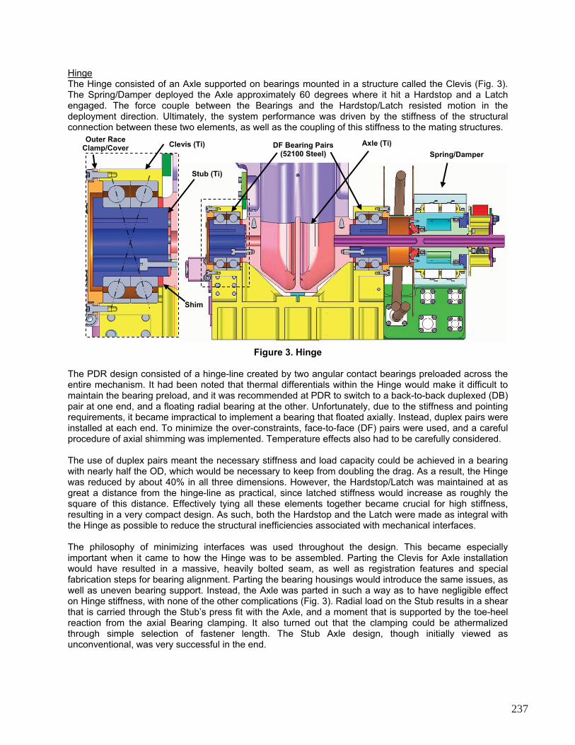
As with the heritage devices, the Spring Motor developed a heritage problem. As the actuator deployed, each spring lamination coiled at a slightly different rate than the one next to it due to the difference in rolling diameter. This required the laminations to slide over each other. The inner laminations were also heavily pinched against the Roller Pin due to the force of all the laminations above. The resulting interlaminar sliding friction and the Roller Pin drag generated enough resistance to the coiling of the inner laminations that they would instead “bunch up” ahead of the Roller Pin in a runaway buckling fashion (Fig. 10). This was the case for nearly the inner third of the laminations, at which point the force from those above was low enough to allow the necessary slippage. The earlier decision to not lubricate the Springs increased the problem, and a few spare (coated) Springs from Galileo were used in the innermost two positions. This helped, but didn’t solve the problem completely (which is probably why it had been deemed ineffective). The Vespel SP-3 (MoS2) Roller Pin Sleeves were wet lubricated with Braycote, and the OD of the Sleeves was increased to give greater mechanical advantage over the rolling friction (though this wasn’t implemented), each with further improvement. The ultimate solution wound up being the heritage solution, which was to band the laminations together with lacing cord. While not graceful, this was the only approach that offered any sense of reliability. The lesson learned was that while heritage should be appropriately scrutinized, don’t be too eager to change a design.
244
Inner Spring Laminations
Buckling
Large OD Roller
w/Braycote
Figure 10. Actuator Spring Buckling
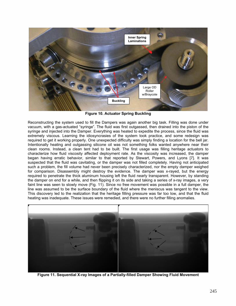
Reconstructing the system used to fill the Dampers was again another big task. Filling was done under vacuum, with a gas-actuated “syringe”. The fluid was first outgassed, then drained into the piston of the syringe and injected into the Damper. Everything was heated to expedite the process, since the fluid was extremely viscous. Learning the idiosyncrasies of the system took practice, and some redesign was required to get it working properly. One unexpected difficulty was simply finding a location for the bell jar. Intentionally heating and outgassing silicone oil was not something folks wanted anywhere near their clean rooms. Instead, a clean tent had to be built. The first usage was filling heritage actuators to characterize how fluid viscosity affected deployment rate. As the viscosity was increased, the damper began having erratic behavior, similar to that reported by Stewart, Powers, and Lyons [7]. It was suspected that the fluid was cavitating, or the damper was not filled completely. Having not anticipated such a problem, the fill volume had never been precisely characterized, nor the empty damper weighed for comparison. Disassembly might destroy the evidence. The damper was x-rayed, but the energy required to penetrate the thick aluminum housing left the fluid nearly transparent. However, by standing the damper on end for a while, and then flipping it on its side and taking a series of x-ray images, a very faint line was seen to slowly move (Fig. 11). Since no free movement was possible in a full damper, the line was assumed to be the surface boundary of the fluid where the meniscus was tangent to the view. This discovery led to the realization that the heritage filling pressure was far too low, and that the fluid heating was inadequate. These issues were remedied, and there were no further filling anomalies.
Figure 11. Sequential X-ray Images of a Partially-filled Damper Showing Fluid Movement
245

Assembling the Hinges and Latches went relatively smoothly, once all the known dimensional discrepancies had been corrected. Special tools were made for pressing in the Bearings and Stub Axles, so that no load was applied across the balls. Fortunately, disassembly had also been considered in the design phase. This came in very handy when one of the Stub Axles was installed improperly and needed to be removed. Simple design features allowed what could have been a real catastrophe to be only a minor inconvenience. Lesson reinforced: always consider disassembly, especially for items with press fits.
Figure 12. Assembled LDM
BoomTo meet alignment requirements, the Boom was bonded using the flight LDM and UDM as fixturing. After functionally verifying the Mechanisms, they were mounted to a jig that represented the deployed Primary Structure and Reflector interfaces, and the Boom was assembled between. All piece-part fabrication tolerances were thereby taken up in the bondlines, and the end-to-end alignment was as good as the jig.
Testing
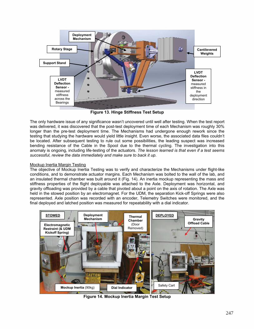
Temp/Atm Deployment and Stiffness TestingThe start of mechanism testing turned out to be a real eye-opening experience. The objectives of the first Temp/Atm Deployment Test were to functionally demonstrate deployment and latching of the Mechanisms at temperature, and to satisfy thermal cycling requirements. Stiffness Testing was then designed to apply a moment to the Hinge, at temperature, and measure the resulting rotational deflection. The Clevis was mounted to a rotation stage having a horizontal axis, and a large weight was cantilevered off the Axle to apply the moment (Fig. 13). The resulting deflection was measured by linear variable displacement transformers (LVDT’s). Slowly rotating the stage through 360 degrees resulted in one complete load cycle and a mapping of the hinge stiffness.
Regrettably, test preparations were neglected due to all the fabrication and assembly issues. In the panic to catch up, the test engineer took many shortcuts and wound up making many mistakes. In the end, far more time and resources were spent fixing the resulting problems than if testing had been delayed to allow for proper preparation. Without going into all the gory and embarrassing details, the following list highlights a number of lessons learned. The most important lesson of all was that test development requires the same level of attention, scrutiny, review, and verification as the hardware to be tested.
� Be sure all test requirements are well established and communicated to all supporting parties � Verify the complete test setup prior to testing. That means functionality, mechanical interfaces,
electrical cabling, thermal control, and especially the data acquisition system are all thoroughly demonstrated under environmental conditions
� When designing GSE to interface with flight hardware, simply duplicate the flight interface rather than try to re-engineer it from scratch
� It’s better to have two simple test fixtures than one complicated one � Make accurate predictions of the expected test performance
246
Deployment Mechanism
LVDTDeflection Sensor -measuredstiffness
across the Bearings
Support Stand
Rotary Stage Cantilevered Weights
LVDTDeflection Sensor -measuredstiffness in
thedeployment
direction
Figure 13. Hinge Stiffness Test Setup
The only hardware issue of any significance wasn’t uncovered until well after testing. When the test report was delivered, it was discovered that the post-test deployment time of each Mechanism was roughly 30% longer than the pre-test deployment time. The Mechanisms had undergone enough rework since the testing that studying the hardware would yield little insight. Even worse, the associated data files couldn’t be located. After subsequent testing to rule out some possibilities, the leading suspect was increased bending resistance of the Cable in the Spool due to the thermal cycling. The investigation into this anomaly is ongoing, including life-testing of the actuators. The lesson learned is that even if a test seems successful, review the data immediately and make sure to back it up.
Mockup Inertia Margin TestingThe objective of Mockup Inertia Testing was to verify and characterize the Mechanisms under flight-like conditions, and to demonstrate actuator margins. Each Mechanism was bolted to the wall of the lab, and an insulated thermal chamber was built around it (Fig. 14). An inertia mockup representing the mass and stiffness properties of the flight deployable was attached to the Axle. Deployment was horizontal, and gravity offloading was provided by a cable that pivoted about a point on the axis of rotation. The Axle was held in the stowed position by an electromagnet. For the UDM, the separation Kick-off Springs were also represented. Axle position was recorded with an encoder, Telemetry Switches were monitored, and the final deployed and latched position was measured for repeatability with a dial indicator.
Deployment Mechanism
STOWED DEPLOYEDThermal Chamber
(DoorRemoved)
Gravity Offload Cable
Electromagnetic Restraint (& UDM Kickoff Spring)
Dial Indicator Mockup Inertia (90kg)Safety Cart
Figure 14. Mockup Inertia Margin Test Setup
247

With spring-driven actuators, demonstrating torque margin was more complicated than just turning down a power supply. The Spring Motor produced torque from two stacks of spring laminations. One stack was decoupled to reduce the torque output by half. Successful deployment under the worse-case-drag conditions therefore demonstrated at least 100% margin. The Latch was similarly handicapped by removing one of the redundant springs, and 100% margin was demonstrated in a maximum deployment velocity scenario.
With a new test engineer, and having learned a lot from the previous testing, things went much more smoothly, but not perfectly. The biggest issues were with the data acquisition system, which still had a number of bugs and other problems. There was also a lot to learn about constructing a thermal chamber. While thermal regulation with heaters and LN2 was fairly straightforward, preventing condensation was not. Water molecules are extremely mobile, and even positive pressure along with purge rates over 15 volume exchanges per hour didn’t eliminate frosting of the hardware. Also, directing GN2 into an LN2
stream can result in snow as the moisture in the GN2 freezes.
Conclusions
The Aquarius Deployment Mechanisms enabled the radar Reflector to be stowed for launch and deployed on-orbit. While the Mechanisms were relatively simple latching hinges, the challenging requirements demanded extreme scrutiny of every design detail. Use of a heritage Spring/Damper Actuator faced the dilemma of trying to maintain heritage while simultaneously having to adapt to the new implementation. Unending fabrication, procurement, and assembly issues caused test preparations to be neglected, which in turn led to terrible testing difficulties. Despite all the challenges and setbacks, the Deployment Mechanisms ultimately exceeded all of their performance requirements. Many important lessons were learned in the process, as described throughout the paper.
References
1. John R. McGuire and Joseph A. Yura, “Advances in the Analysis and Design of Constant-Torque Springs”, 30th Aerospace Mechanisms Symposium, May 1996, pp. 205-220
2. Robert L. Fusaro, “NASA Space Mechanisms Handbook”, NASA-GRC, NASA/TP—1999-206988, July 1999, pp. 145-152 (damper), pp. 94-95 (telemetry switch)
3. Jack D. Harper, “Viscous Rotary Vane Actuator/Damper”, 10th Aerospace Mechanisms Symposium, April 1976, pp. 198-207
4. “L4 Aquarius Mechanisms Subsystem Requirements, Initial Release”, JPL Document D-35155
Boom
UDM
LDM
Figure 15. Final Deployment Boom Assembly
5. Alexander H. Slocum, “Precision Machine Design”, Society of Manufacturing Engineers, Dearborn MI, Jan 1992, pp. 464-468, 539-543
6. Alan R. Leveille, “Bearings Analysis Program Version 10 C”, Licensed by The Aerospace Corporation, El Segundo CA
7. Alphonso Stewart, Charles Powers, and Ron Lyons, “Improvements for Rotary Viscous Dampers used in Spacecraft Deployment Mechanisms”, 32nd Aerospace Mechanisms Symposium, May 1998
248