Embed Size (px)
Citation preview

EXPRESSION OF INTEREST (EOI) FOR MANUFACTURING AND SUPPLY OF SELF-PROPELLED TUNNEL RESCUE TRAIN FOR BROAD GAUGE ROUTE OF INDIAN RAILWAYS
(Development of Specification): Motive Power Directorate of Research, Designs & Standards Organisation (RDSO), Lucknow, under the
Ministry of Railways (MOR), is interested in developing specification for Self-Propelled Tunnel Rescue
Train for Broad Gauge route of IR. Details of such items, for which this part of EOI intends to cover the
stage of development of specification, are as follows:
S.No. Description Details of Specification
Contact Details
1 FUNCTIONAL REQUIREMENT SPECIFICATION FOR “BG SELF-PROPELLED TUNNEL RESCUE TRAIN” (Development of Specification)
RDSO Specification
No. MP-0.08.00.116
(Rev.- 00) July’2020
Pankaj Saxena, Dy. Director/Motive Power‐Hyd Room No: 110 Building: Manak Bhawan Tel. No.: 0522‐2465733, Mob no. 9794863118 Email: [email protected]
a) Details of the above-mentioned Functional Requirement Specification (FRS) are attached herewith
as Annexure - C.
b) Purpose of this EOI is developing of Technical Specification of TRT, based on FRS.
c) Technical specification shall be such as against which different offers received can be compared, TRT
can be manufactured, supplied, verified and tested by the Inspecting authority, without any
reasonable doubt/confusion.
d) Also, equipments/facilities not mentioned in FRS, but required as per current international practices,
may also be included.
e) Apart for the technical specification, past experience of bidder in supply and manufacturing of TRT is
also being asked, as mentioned in the Annexure-A, for the purpose of defining a reasonable
qualifying critiera for the bidding.
f) Firms who have enough experience/capabilities in the field are requested to submit details in the
prescribed format attached herewith to the concerned officer mentioned above.
In case of any doubt, please contact the concerned officer mentioned above via email or phone, within
the office timing (9:00 to 17:30 hours) on any working day (Monday to Friday).
Annexures: A, B & C
Executive Director Motive Power Directorate

Annexure-A
FORMAT FOR LETTER OF RESPONSE
Respondents Ref No.: Date:
Shri Pankaj Saxena Deputy Director, Motive Power Research Designs & Standards Organization Ministry of Railways Manak Nagar, Lucknow INDIA- 226011
Dear Sir,
Subject: RESPONSE TO – EOI FOR PARTICIPATION __________________________ 1. We, the undersigned, offer the following information in response to the Expression of Interest sought
by you vide your Notification No._______, dated _____. 2. We are duly authorized to represent and act on behalf of ________________ (hereinafter the
“respondent”) 3. We have examined and have no reservations to the EOI Document including Addenda No(s)
______________________. 4. I / We understand that
a) This EOI is for finalization of Technical Specification and Scope of Supplies and not for the actual
supplies.
b) IR may float a separate Tender (based on their requirement) with all conditions like Eligibility
Criteria defined and Our Participation in this EOI doesn’t guarantee any qualification to that
tender.
c) IR is free to initiate different mode/method for appointment of activities / services / including, but not limited to, those not covered in the scope of this for which IR feels other modes of appointment are better suited.
5. We are attaching with this letter, the copies of original documents defining: - a) The Respondent’s legal status; b) Its principal place of business; c) Its place of incorporation (if respondents are corporations); or its place of registration (if
respondents are cooperative institutions, partnerships or individually owned firms); d) Self-certified financial statements of Last three years, clearly indicating the financial turn over and
net worth. e) Copies of any market research, business studies, feasibility reports and the like sponsored by the
respondent, relevant to the project under consideration.
6. We shall assist MOR and/or its authorized representatives to obtain further clarification from us, if needed.
a) RDSO and/or its authorized representatives may contact the following nodal persons for further information on any aspects of the Response:
S. No. Contact Name Address Telephone E Mail
7. This application is made in the full understanding that: a) Information furnished in response to EOI may be used confidentially by RDSO for the purpose of
development of the Specification. b) RDSO reserves the right to reject or accept any or all applications, cancel the EOI and subsequent
bidding process without any obligation to inform the respondent about the grounds of same. c) We confirm that we are interested in participating in development of the Specification.
8. We certify that our turnover and net worth in the last three years is as under:
Financial Year Turn over Net worth
9. In response to the EOI we hereby submitting the following details annexed to this application. 9.1 Detailed technical specifications to meet the given functional requirements including
alternative specification, if any. 9.2 Details of self-propelled TRTs manufactured over last 10 years. 9.3 Details of self-propelled TRT supplies made over last 10 years. 9.4 Details of supplies made in the field of other similar application. 9.5 Details of man-power with their qualification and experience. 9.6 Details of Patent held and MoU/agreement with OEM of equipments/rolling stock, proposed to
be used in TRT 9.7 Undertaking as per Annexure-B
10. The undersigned declare that the statements made and the information provided in the duly completed application are complete, true, and correct in every detail. We also understand that in the event of any information furnished by us being found later on to be incorrect or any material information having been suppressed, RDSO may delete our name from the list of potential bidders. We further understand that RDSO will give first preference to the applicants considered relevant for the purpose.
11. Our response is valid till (date in figures and words):_____________________________________ Yours sincerely, (Sign) Name In the Capacity of Duly authorized to sign the response for and on behalf of Date:
Annexure-B
(To be taken on non-judicial stamp paper of appropriate value as applicable in the respective state and duly notarised and witnessed)
UNDERTAKING I, son/daughter of ……………… aged about …..... Years resident of ………….. do hereby solemnly affirm as under: 1. That the deponent is the Authorised signatory of (Name of the Sole Proprietorship
Concern/Partnership Firm/ Registered Company/ Joint Venture). 2. That the deponent declares on behalf of (Name of the Sole Proprietorship Concern/ Partnership
Firm/ Registered Company/Joint Venture) that:
a) In regard to matters relating to the security and integrity of the country, no charge sheet has been filed by an agency of the Government and/or conviction awarded by a Court of Law for an offence committed by the -----------------------------------(name of the entity) or by any sister concern of the ----------------------------------(name of the entity) would result in disqualification.
b) In regard to matters other than the security and integrity of the country, ---------------(name of
the entity) has not been convicted by a Court of Law or indicted / passed any adverse order by a regulatory authority against it or it’s any sister concern which relates to a grave offence, or would constitute disqualification. Grave offence is defined to be of such a nature that it outrages the moral sense of the community.
DEPONENT
VERIFICATION
I declare that the contents of para 1 to 2 above are true as per my knowledge and nothing has been hidden.
DEPONENT
(For official use only)
dsoy ljdkjh iz;ksx gsrq
Hkkjr ljdkj
jsy ea=ky;
GOVERNMENT OF INDIA MINISTRY OF RAILWAYS
Functional Requirement Specification (FRS) for
Self-Propelled Tunnel Rescue Train (TRT) for Broad Gauge Network of Indian Railways
Specification no. MP- 0.08.00.116 (Rev.- 00)
July - 2020
Issued by
vuqla/kku vfHkdYi ,oa ekud laxBu] Ekkud uxj]
y[kuÅ - 226 011 RESEARCH DESIGNS AND STANDARDS ORGANISATION
MANAK NAGAR, LUCKNOW– 226011
Annexure - C
ISO 9001 : 2008 Specification no. MP-0.08.00.116 Revision No: 00 Issued: July‟2020
Functional Requirement Specification of Self-Propelled Tunnel Rescue Train (TRT)
Page 2 of 10
C O N T E N T S
Contents 1. INTRODUCTION:......................................................................................................................................... 3
2. COMPOSITION OF SELF-PROPELLED TUNNEL RESCUE TRAIN (TRT): ......................................................... 3
3. MAIN FEATURES OF TRT: ........................................................................................................................... 3
4. OPERATIONAL AND ENVIRONMENTAL CONDITIONS: ............................................................................... 4
5. QUALIFYING CRITERIA:............................................................................................................................... 5
6. SCOPE OF WORK/SUPPLY: ......................................................................................................................... 5
7. GENERAL DESIGN REQUIREMENTS: ........................................................................................................... 6
8. TRAINING: .................................................................................................................................................. 8
9. WARRANTY PERIOD: .................................................................................................................................. 9
10. ANNUAL MAINTENANCE CONTRACT: .................................................................................................... 9
11. INSPECTION, COMMISSIONING AND TESTING OF TUNNEL RESCUE TRAIN: ......................................... 9
12. ADDRESS FOR COMMUNICATION: ...................................................................................................... 10
List of Annexures
Annexure-I Diagram no.1D of Indian Railway BG Schedule of Dimension (IRSOD)
Annexure-II INDIAN RAILWAYS SCHEDULE OF DIMENSIONS 1676mm Gauge (BG)
Annexure-III Para 522 of Indian Railway Permanent Way Manual (IRPWM) June 2020
Annexure-IV Para 525 of Indian Railway Permanent Way Manual (IRPWM) June 2020
Annexure-V General arrangement drawings Under frame of AC3 Tier (SG) LHB type Coaches
Annexure-VI Bogie General Arrangement for ACCN(EOG)
Annexure-VII Preliminary Sketch of Bogie Container flat wagon type “BLCS (A Car)”
ISO 9001 : 2008 Specification no. MP-0.08.00.116 Revision No: 00 Issued: July‟2020
Functional Requirement Specification of Self-Propelled Tunnel Rescue Train (TRT)
Page 3 of 10
1. INTRODUCTION:
1.1. Indian Railways (IR) has a vast network of Broad Gauge (1676 mm) railway lines including many long tunnels. The longest tunnel over IR has been opened to traffic recently in Jammu & Kashmir region. This tunnel is 11 km long and thus poses many challenges in terms of rescue operations in case of accident / fire. IR has therefore decided to procure Self-Propelled Tunnel Rescue Train (TRT) for this purpose over such sections.
1.2. The technical requirements mentioned in this document are the basic features of
TRT. Further detailing of these requirements shall be done later. 2. COMPOSITION OF SELF-PROPELLED TUNNEL RESCUE TRAIN (TRT):
TRT shall consist of 5 cars, as indicated below, to accommodate all equipments / tools required for handling disaster:
2.1. Driving cum Transportation / Rescue car (DPC-1) 2.2. Fire Fighting Water Tank Wagon (FFWT) 2.3. Equipment Car 2.4. Medical car 2.5. Driving cum Transportation Car/ Rescue Car (DPC-2) )
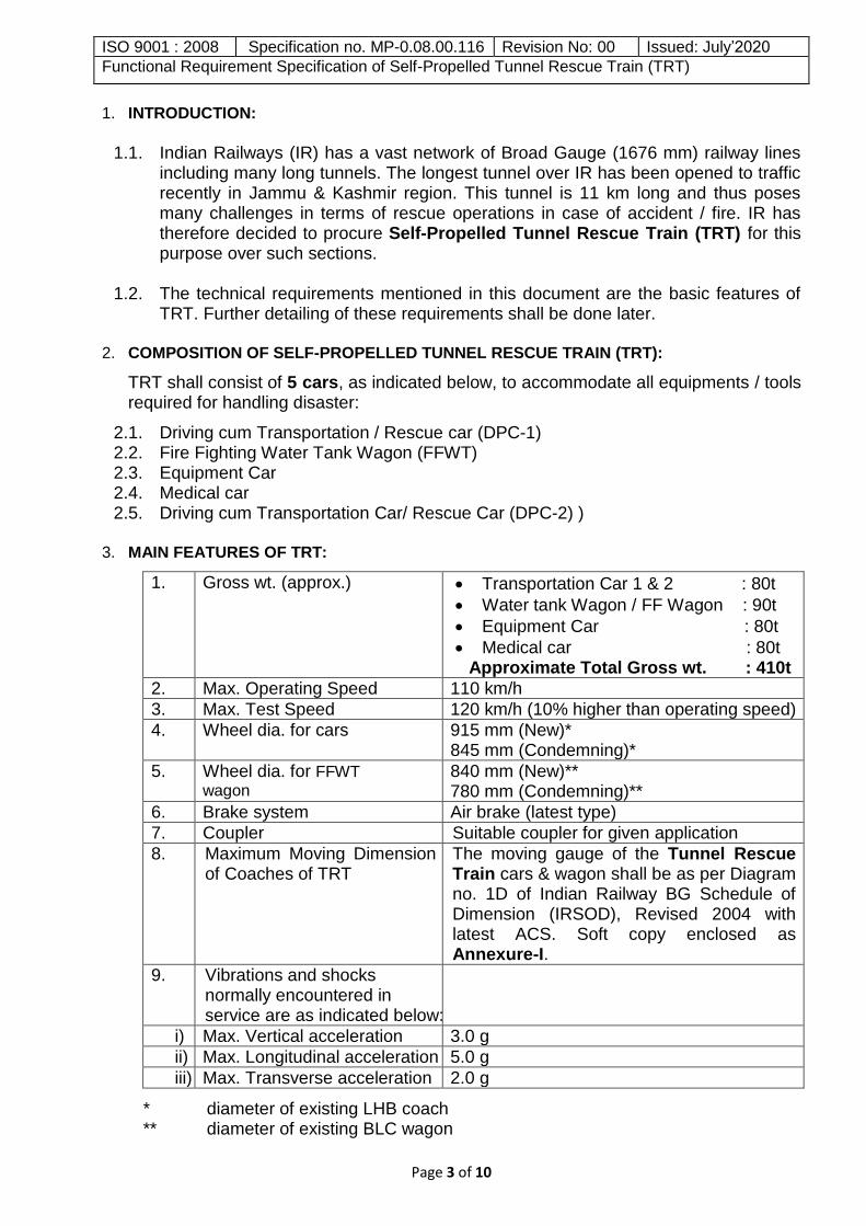
3. MAIN FEATURES OF TRT:
1. Gross wt. (approx.) Transportation Car 1 & 2 : 80t
Water tank Wagon / FF Wagon : 90t
Equipment Car : 80t
Medical car : 80t Approximate Total Gross wt. : 410t
2. Max. Operating Speed 110 km/h
3. Max. Test Speed 120 km/h (10% higher than operating speed)
4. Wheel dia. for cars 915 mm (New)* 845 mm (Condemning)*
5. Wheel dia. for FFWT
wagon 840 mm (New)** 780 mm (Condemning)**
6. Brake system Air brake (latest type)
7. Coupler Suitable coupler for given application
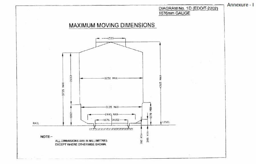
8. Maximum Moving Dimension of Coaches of TRT
The moving gauge of the Tunnel Rescue Train cars & wagon shall be as per Diagram no. 1D of Indian Railway BG Schedule of Dimension (IRSOD), Revised 2004 with latest ACS. Soft copy enclosed as Annexure-I.
9. Vibrations and shocks normally encountered in service are as indicated below:
i) Max. Vertical acceleration 3.0 g
ii) Max. Longitudinal acceleration 5.0 g
iii) Max. Transverse acceleration 2.0 g
* diameter of existing LHB coach ** diameter of existing BLC wagon

ISO 9001 : 2008 Specification no. MP-0.08.00.116 Revision No: 00 Issued: July‟2020
Functional Requirement Specification of Self-Propelled Tunnel Rescue Train (TRT)
Page 4 of 10
4. OPERATIONAL AND ENVIRONMENTAL CONDITIONS: TRT shall have to work under the following conditions including trials indicated at para 4.2.3:
4.1. Track Parameters:
Gauge Broad Gauge 1676mm Schedule of dimensions
Indian Railways Schedule of Dimensions for Broad Gauge (1676mm), Revised 2004 (copy enclosed as Annexure-II)
Sharpest curve to be negotiated
Horizontal-175 m radius Vertical - 2500 m for group C, D and E routes
Sharpest turnout to be negotiated
1 in 8½ turnouts on pre stressed concrete sleepers for 60 kg (UIC) or 52 kg rail
Permissible speed at turn outs
1 in 8½ curved switch 52/60 kg on Pre-Stressed Concrete
(PSC) sleepers – 15 kmph
1 in 8½ symmetrical split with curved switches 52/60 kg on PSC sleepers- 30 kmph
1 in 12 curved switch 52/60 kg on PSC sleepers - 30 kmph
Maximum super elevation
140 mm for group D and E routes
Maximum cant deficiency
For speed > 100 kmph : 100 mm
For speed upto 100 kmph : 75 mm
As per Para 404 (2) of IRPWM, June 2020
Maximum Gradient
1:37
Permissible Track Tolerances
As given in Para 522 of Indian Railway Permanent Way Manual (IRPWM) June 2020, (relevant pages attached as Annexure-III)
Gauge
As mentioned in Para 525 of Indian Railway Permanent Way Manual (IRPWM) June 2020, (relevant pages attached as Annexure-IV).
Straight Track -6mm +6mm
Curved Track with more than 440m radius -6mm +15mm
Curved Track with less than 440m radius upto +20mm
4.2. Track Classification
4.2.1. The Broad Gauge (BG) lines on Indian Railways, as per Indian Railways
Permanent Way Manual, have been classified into six groups, „A‟ to „E‟ on the basis of the future maximum permissible speed as under:
i) Group 'A' - Speeds up to 160 kmph ii) Group 'B' - Speeds up to 130 kmph iii) Group 'C‟ - Suburban Sections of Mumbai, Delhi, Chennai and Kolkata iv) Group „D‟ Spl.- Speeds upto 110 kmph & annual traffic density is 20 GMT or
more.
ISO 9001 : 2008 Specification no. MP-0.08.00.116 Revision No: 00 Issued: July‟2020
Functional Requirement Specification of Self-Propelled Tunnel Rescue Train (TRT)
Page 5 of 10
v) Group „D‟- Speeds upto 110 kmph & annual traffic density is less than 20 GMT.
vi) Group „E‟ - All other Sections and branch lines with speed upto 100 kmph.
4.2.2. On IR, there are following four speed bands. The train speed limit is regulated in accordance with track structure and maintenance standards in respective speed bands:
i) Upto 100kmph ii) From 100 kmph upto 110 kmph iii) From 110 kmph to 130 kmph iv) From 130 kmph to 160 kmph
4.2.3. Service worthiness trials of TRT shall be carried out on track as per speed
band „upto 100 kmph‟ and „100 kmph to 110 kmph‟ at test speed of 110kmph and 120 kmph, respectively, which is 10% higher than the operating speed on respective track. However, selection of track shall be done as per criteria laid down by RDSO.
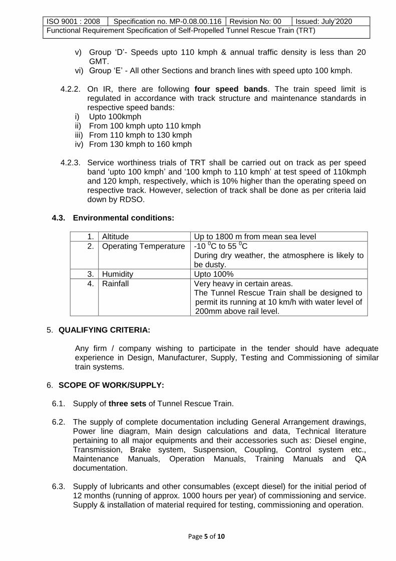
4.3. Environmental conditions:
1. Altitude Up to 1800 m from mean sea level
2. Operating Temperature -10 0C to 55 0C During dry weather, the atmosphere is likely to be dusty.
3. Humidity Upto 100%
4. Rainfall Very heavy in certain areas. The Tunnel Rescue Train shall be designed to permit its running at 10 km/h with water level of 200mm above rail level.
5. QUALIFYING CRITERIA:
Any firm / company wishing to participate in the tender should have adequate experience in Design, Manufacturer, Supply, Testing and Commissioning of similar train systems.
6. SCOPE OF WORK/SUPPLY:
6.1. Supply of three sets of Tunnel Rescue Train.
6.2. The supply of complete documentation including General Arrangement drawings, Power line diagram, Main design calculations and data, Technical literature pertaining to all major equipments and their accessories such as: Diesel engine, Transmission, Brake system, Suspension, Coupling, Control system etc., Maintenance Manuals, Operation Manuals, Training Manuals and QA documentation.
6.3. Supply of lubricants and other consumables (except diesel) for the initial period of 12 months (running of approx. 1000 hours per year) of commissioning and service. Supply & installation of material required for testing, commissioning and operation.

ISO 9001 : 2008 Specification no. MP-0.08.00.116 Revision No: 00 Issued: July‟2020
Functional Requirement Specification of Self-Propelled Tunnel Rescue Train (TRT)
Page 6 of 10
6.4. Supply of sets of special tools, commissioning & testing instruments etc. which shall be required at Indian Railway‟s workshop for carrying out major overhaul and at maintenance depot for regular maintenance of the BG Tunnel Rescue Train Cars / Wagon and the supply of spares so as to meet the maintenance requirements for five-year period.
6.5. Submit list of infrastructure & facilities (with price) required for maintenance and overhaul of BG Tunnel Rescue Train offered.
6.6. Arrange all necessary technical supervision for the installation, testing and commissioning of the BG Tunnel Rescue Train.
7. GENERAL DESIGN REQUIREMENTS:
7.1. Design details of TRT:
7.1.1. The Tunnel rescue Train cars shall be made of Stainless Steel or Aluminum, on proven design underframe and bogie. Underframe and bogie of LHB may be opted for all cars coaches, except for FFWT, for which BLC underframe and bogie may be opted. In case, the bidder opts for LHB/BLC underframe and bogie, necessary detailed drawings of these platform(s) shall be provided by IR under Non-Disclosure Agreement (NDA) (general arrangement drawings of these two underframes and bogie are enclosed as Annexure- V To VII).
7.1.2. The Tunnel Rescue Train shall have provision to split into two separate trains and each of them shall be capable of operating bi-directionally, independently, as per site requirement. The first train consisting of three cars i.e. Transportation car-1, Fire Fighting Water Tank Wagon and Equipment Car may stay at accident site to carry out accident management operation and move also. The second train consisting of two cars i.e. Medical car and Transportation car-2 can be used as shuttle service for evacuation of passengers, away from accident site and then back to accident site.
7.1.3. The supplier shall be fully responsible for weight balancing, FEA, dynamic simulation, successful service worthiness testing, both static and dynamic on IR track, in fully furnished condition to ascertain the safety and running stability of TRT, even if it chooses to use LHB/BLC type underframe and bogie, already in service on IR.
7.1.4. The list of Hydraulic Re-railing Equipment (HRE) and Hydraulic Rescue device (HRD), along with approx. weight and space requirement, being used by IR (to be supplied by IR) and to be provided in Equipment car shall be provided by IR. The firm will take into account to accommodate these equipments, inter-alia other equipments.
7.1.5. Supplier shall supply the TRTs fully equipped to successfully carry out the rescue operation, except listed HRE and HRD equipments.
ISO 9001 : 2008 Specification no. MP-0.08.00.116 Revision No: 00 Issued: July‟2020
Functional Requirement Specification of Self-Propelled Tunnel Rescue Train (TRT)
Page 7 of 10
7.2. The design details of individual cars shall be as follows: -
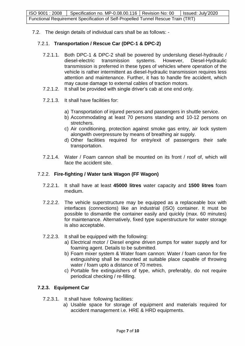
7.2.1. Transportation / Rescue Car (DPC-1 & DPC-2)
7.2.1.1. Both DPC-1 & DPC-2 shall be powered by underslung diesel-hydraulic / diesel-electric transmission systems. However, Diesel-Hydraulic transmission is preferred in these types of vehicles where operation of the vehicle is rather intermittent as diesel-hydraulic transmission requires less attention and maintenance. Further, it has to handle fire accident, which may cause damage to external cables of traction motors.
7.2.1.2. It shall be provided with single driver‟s cab at one end only.
7.2.1.3. It shall have facilities for:
a) Transportation of injured persons and passengers in shuttle service. b) Accommodating at least 70 persons standing and 10-12 persons on
stretchers. c) Air conditioning, protection against smoke gas entry, air lock system
alongwith overpressure by means of breathing air supply. d) Other facilities required for entry/exit of passengers their safe
transportation.
7.2.1.4. Water / Foam cannon shall be mounted on its front / roof of, which will face the accident site.
7.2.2. Fire-fighting / Water tank Wagon (FF Wagon)
7.2.2.1. It shall have at least 45000 litres water capacity and 1500 litres foam medium.
7.2.2.2. The vehicle superstructure may be equipped as a replaceable box with interfaces (connections) like an industrial (ISO) container. It must be possible to dismantle the container easily and quickly (max. 60 minutes) for maintenance. Alternatively, fixed type superstructure for water storage is also acceptable.
7.2.2.3. It shall be equipped with the following: a) Electrical motor / Diesel engine driven pumps for water supply and for
foaming agent. Details to be submitted. b) Foam mixer system & Water foam cannon: Water / foam canon for fire
extinguishing shall be mounted at suitable place capable of throwing water / foam upto a distance of 70 metres.
c) Portable fire extinguishers of type, which, preferably, do not require periodical checking / re-filling.
7.2.3. Equipment Car
7.2.3.1. It shall have following facilities:
a) Usable space for storage of equipment and materials required for accident management i.e. HRE & HRD equipments.

ISO 9001 : 2008 Specification no. MP-0.08.00.116 Revision No: 00 Issued: July‟2020
Functional Requirement Specification of Self-Propelled Tunnel Rescue Train (TRT)
Page 8 of 10
b) A crane with (minimum load capacity of 750 kg) to be mounted on the superstructure.
c) Diesel Alternator set of suitable capacity for catering to the electrical load of breathing air compressor & other electrical loads, crane & disaster management equipment. Backup power supply arrangement, in case of failure of Diesel-Alternator set, to be suggested.
d) Breathing air compressor, booster pump, breathing air filling station and storage frame for breathing air cylinders.
e) Work bench with drawer, vice, tool boards and shelf f) Fire extinguishers g) Racks h) Tool boards
7.2.4. Medical Van
It shall be air-conditioned and have following facilities: a) Breathing air supply b) 10-12 berths for injured persons. c) A small operation theatre for carrying out minor emergency surgery. d) A medical staff room with racks for keeping medical items such as drugs,
dressing & other medical equipments and a refrigerator for medicine
7.3. Brake System
7.3.1. The TRT shall be provided with latest type of twin pipe graduated release computerized controlled air brake system. It shall be UIC approved type and meet all UIC requirements.
7.3.2. To enable TRT to be hauled by locomotive in case of failure, there shall be provision of connecting the brake pipes of TRT with loco so that the brake of TRT can be controlled by driver‟s cab of locomotive. The transmission shall be disengaged before towing/hauling of TRT.
7.4. TRT shall incorporate all essential features necessary to yield low maintenance
requirements, easy maintainability, high reliability in operation and high efficiency. The Tenderer shall incorporate all the items required for proper functioning of the BG Tunnel Rescue Train in accordance with the current international practices.
7.5. Driver’s cab:
7.5.1. Transportation Car-1 and Transportation Car-2 shall be provided with single driver‟s cab to meet the requirement mentioned at clause no. 7.1.1.
7.5.2. Each driver‟s cab shall have provision of breathing air supply and Air-conditioning / heating.
7.5.3. Each driver‟s cab shall be equipped with Thermal imaging and Infrared camera
alongwith a display in the cab.
8. TRAINING:

ISO 9001 : 2008 Specification no. MP-0.08.00.116 Revision No: 00 Issued: July‟2020
Functional Requirement Specification of Self-Propelled Tunnel Rescue Train (TRT)
Page 9 of 10
8.1. The Supplier shall provide training at the manufacturer‟s place to adequate number of Indian Railway personnel so that they acquire full knowledge of major assembly/sub-assembly used in TRT. The training shall be helpful in trouble-shooting, maintenance and operation of the TRT.
8.2. Besides the above, adequate number of maintenance and operating staff shall
also be trained in operation and maintenance TRT and its major equipments likes engine, transmission controls, electrical system etc. at the homing shed during the commissioning of the TRT.
9. WARRANTY PERIOD:
24 months from the date of placement in service or 30 months from date of delivery whichever is earlier.
10. ANNUAL MAINTENANCE CONTRACT:
10.1. The tenderer shall be required to quote for a Comprehensive Annual Maintenance Contract for the Tunnel Rescue Train, which will be inclusive of all spares, material and labour costs. The duties and taxes as applicable should be indicated separately. All consumables required for day to day operation shall be arranged by Railways.
10.2. AMC agreement for each installation will be signed between the consignee and the Supplier if opted for by the consignee. The detailed terms and conditions of AMC shall be as given in the following clauses:
10.2.1. The duration of AMC shall be 5 years from the date of expiry of warranty.
Rates for AMC shall be quoted by on annual basis which will remain applicable
during the 5 years duration of AMC and not subject to any variation except any
statutory changes in taxes and duties as compared to quoted rates.
10.2.2. The Tenderer must confirm willingness to offer AMC services at all consignee
locations without any preconditions.
10.2.3. The AMC should include complete responsibility for the bought-out of sub-
assemblies and components required for maintenance.
11. INSPECTION, COMMISSIONING AND TESTING OF TUNNEL RESCUE TRAIN:
11.1. The whole of the materials or fittings used for works covered by the specification
shall be subject to inspection by the Inspecting Officer, authorized by IR and shall be to his entire satisfaction.
11.2. After successful completion of inspection and tests at manufacturer‟s works,
clearance for dispatch shall be given. 11.3. The Tunnel Rescue Train shall be commissioned by the Supplier within 8 weeks
after intimation by the consignee. The consignee railways will issue a commissioning certificate after it has been successfully commissioned.
11.4. After commissioning, Oscillation Trials to prove the service worthiness of TRT shall be undertaken on the BG tracks specified at Para 4.2.3 upto test speed of 120 kmph. Indian Railway is in process of switching over to testing criteria from “3rd

ISO 9001 : 2008 Specification no. MP-0.08.00.116 Revision No: 00 Issued: July‟2020
Functional Requirement Specification of Self-Propelled Tunnel Rescue Train (TRT)
Page 10 of 10
Criteria committee’s Report of RDSO” to “UIC-518/EN14363 standards”. The trial may be conducted from either criteria, as applicable at the time of delivery of TRT. However, final decision in this regard shall be taken by IR. The vehicle shall be capable of successfully undergoing testing as per both the criteria.
11.5. After the successful Oscillation trials, performance tests of TRT (braking tests,
holding test, satisfactory working & capability of the equipments provided, tests to assess efficacy of TRT to achieve the laid down requirements) as per approved plan, shall be conducted.
11.6. During the Inspection/ trials, if any problems are thrown up, which warrants a re-
check of the design/ manufacture/ quality of the equipment and components, action will be taken as may be necessary by the Supplier to carry out the required investigations and to incorporate the improvements considered most appropriate to reach compliance with the specification & to ensure specified reliability and performance without any extra costs to the Purchaser.
12. ADDRESS FOR COMMUNICATION:
Dy. Director/Motive Power‐Hyd Room No: 110, Manak Bhawan Research Designs & Standards Organization Government of India -Ministry of Railways Manak Nagar Lucknow Uttar Pradesh India Pin: 226 011
Tel. No.: 0522‐2465733, Mob no. 9794863118 Email ID: [email protected]
-------------------------

¦ÉÉ®úiÉÒªÉ ®äú±É +ɪÉÉ¨É +xÉÖºÉÚSÉÒ
1676 ʨÉ.¨ÉÒ. +ɨÉÉxÉ (¤ÉÒ.VÉÒ.)
INDIAN RAILWAYS
SCHEDULE OF DIMENSIONS 1676mm Gauge
(BG)
ºÉƶÉÉäÊvÉiÉ, 2004 REVISED, 2004
Annexure - II

1
SCHEDULE OF DIMENSIONS-1676mm, GAUGE
SHEDULE OF DIMENSIONS-1676MM GAUGE
Schedule of Dimensions for Indian Railways, 1676mm Gauge
Dear Sir/Dear Sirs,
With their circular letter No. 735-W. of 1922, the Railway Board issued a Schedule of Maximum, Minimum and Recommended Dimensions to be observed on all 1676mm gauge Railways in India. In that Schedule, certain dimensions of the previous schedule of the year 1913 were modified with the object of permitting the use of enlarged rolling stock.
2. The Schedule of Dimensions of 1922 contained two distinct sections, namely, a schedule of "Maximum and Minimum Dimensions" which was considered to enable the proposed larger vehicles to run with about the same degree of safety as that which was previously obtained on the older Railways with existing stock, and a schedule of "Recommended Dimensions" intended to provide approximately the same clearances from fixed structures for the future larger vehicles as the 1913 schedule gave for existing vehicles.
3. In their circular letter No. 232-Tech.dated the 8th February, 1926, the Railway Board gave instructions that the Recommended Dimensions given in the 1922 Schedule were to be observed on important Railways in all new works and alterations to existing works. These orders were modified in letter No. 232-Tech. of the 26th April, 1926, which allowed a relaxation in the case of certain recommended dimensions, the adoption of which would involve heavy expenditure in remodelling works.
4. In 1929, it was found desirable further to amend the Schedule of 1922 in order to introduce certain improve-ments in the light of experience gained since it was issued, and to provide the clearances required by electric traction equipment on lines which were likely to be electrified in the future. A few special dimensions were also required for "Standard C" railways as defined in the "Rules for preparation of Railway Projects 1926 - Chapter III, Standards of Construction".
5. The Schedule I issued in 1929, therefore, embodied these amendments and additions and the opportunity was taken to omit from this schedule many dimensions occurring in the 1922 Schedule and its predecessors which were more of the nature of current practice than essential for safe working. These were therefore, relegated to Schedule II, Recommended Dimensions.
6. Among the more important changes introduced in the 1929 Schedule, were an increase in the minimum height above rail level for overhead structures to 5410mm and increase to 2360mm in the horizontal distance to a fixed structure up to 3355mm above rail level, a reduction in this distance to 2135mm at 4420mm above rail level, and a reduction also in the clearance to fixed structures from rail level to 1065mm above rail level on bridges and in tunnels. The last three changes were intended to allow for a reduction in tunnel sections and an improvement in the disposition of bracing of bridge girders without sacrificing safety.
7. In 1936, however, the financial stringency on Railways brought to the front the urgent necessity for
restricting capital expenditure to a minimum. The falling off in Railway traffic generally and the increasing demand for light fast units to compete with motor bus transport also made the introduction of heavier engines and 3660mm wide stock on Railways improbable. In these circumstances it was found desirable to alter the dimensions prescribed in Schedule I of the 1929 Dimensions and to revert to the maximum and minimum dimensions in the 1922 Schedule in several important respects. Railway administrations were advised of these alterations through correction slip no. 14 of 1 st December, 1936 to the 1929 Schedule. These alterations were not, however, intended to prevent the introduction of 3660mm stock at some future date, should this prove necessary. It had, therefore, been expressly laid down that the modifications made in Chapter I of Schedule I, were not to apply to Tunnels, Through and Semi-through Girder Bridges in respect of which the Standard Dimensions of 1929 would continue to apply.
2
SCHEDULE OF DIMENSIONS-1676mm, GAUGE
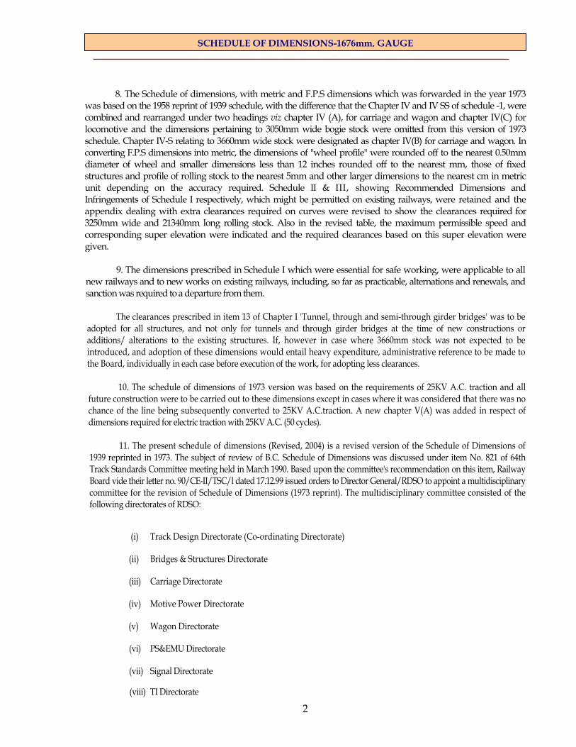
8. The Schedule of dimensions, with metric and F.P.S dimensions which was forwarded in the year 1973
was based on the 1958 reprint of 1939 schedule, with the difference that the Chapter IV and IV SS of schedule -1, were combined and rearranged under two headings viz chapter IV (A), for carriage and wagon and chapter IV(C) for locomotive and the dimensions pertaining to 3050mm wide bogie stock were omitted from this version of 1973 schedule. Chapter IV-S relating to 3660mm wide stock were designated as chapter IV(B) for carriage and wagon. In converting F.P.S dimensions into metric, the dimensions of "wheel profile" were rounded off to the nearest 0.50mm diameter of wheel and smaller dimensions less than 12 inches rounded off to the nearest mm, those of fixed structures and profile of rolling stock to the nearest 5mm and other larger dimensions to the nearest cm in metric unit depending on the accuracy required. Schedule II & III, showing Recommended Dimensions and Infringements of Schedule I respectively, which might be permitted on existing railways, were retained and the appendix dealing with extra clearances required on curves were revised to show the clearances required for 3250mm wide and 21340mm long rolling stock. Also in the revised table, the maximum permissible speed and corresponding super elevation were indicated and the required clearances based on this super elevation were given.
9. The dimensions prescribed in Schedule I which were essential for safe working, were applicable to all
new railways and to new works on existing railways, including, so far as practicable, alternations and renewals, and sanction was required to a departure from them.
The clearances prescribed in item 13 of Chapter I 'Tunnel, through and semi-through girder bridges' was to be
adopted for all structures, and not only for tunnels and through girder bridges at the time of new constructions or additions/ alterations to the existing structures. If, however in case where 3660mm stock was not expected to be introduced, and adoption of these dimensions would entail heavy expenditure, administrative reference to be made to the Board, individually in each case before execution of the work, for adopting less clearances.
10. The schedule of dimensions of 1973 version was based on the requirements of 25KV A.C. traction and all
future construction were to be carried out to these dimensions except in cases where it was considered that there was no chance of the line being subsequently converted to 25KV A.C.traction. A new chapter V(A) was added in respect of dimensions required for electric traction with 25KV A.C. (50 cycles).
11. The present schedule of dimensions (Revised, 2004) is a revised version of the Schedule of Dimensions of
1939 reprinted in 1973. The subject of review of B.C. Schedule of Dimensions was discussed under item No. 821 of 64th Track Standards Committee meeting held in March 1990. Based upon the committee's recommendation on this item, Railway Board vide their letter no. 90/CE-II/TSC/l dated 17.12.99 issued orders to Director General/RDSO to appoint a multidisciplinary committee for the revision of Schedule of Dimensions (1973 reprint). The multidisciplinary committee consisted of the following directorates of RDSO:
(i) Track Design Directorate (Co-ordinating Directorate)
(ii) Bridges & Structures Directorate
(iii) Carriage Directorate
(iv) Motive Power Directorate
(v) Wagon Directorate
(vi) PS&EMU Directorate
(vii) Signal Directorate
(viii) TI Directorate

3
SCHEDULE OF DIMENSIONS-1676mm, GAUGE
The present schedule of dimensions (Revised, 2004) consists of only metric units. All dimensions in FPS units are
deleted. The following modifications have been done over the structure of Schedule of Dimensions of 1973. (a) Only two schedules - Schedule I & Schedule II, are provided in this revised Schedule of Dimensions. Schedule-I
consists of those items which are mandatory and have to be observed on all 1676mm Gauge Railways in India. It is mandatory and contains the items of Schedule-I & certain selected items of Schedule-II of 1973 version of Schedule of Dimensions.
(b) Schedule-II consists of items included in Schedule-III of 1973 version of Schedule of Dimensions. (c) For maximum moving dimensions, profile shown in diagram ID (EDO/T-2202) is being adopted which is based
on the two profiles viz EDO/T-1043( for goods stock) and EDO/T-2227 (for double decker coach) approved by Railway Board vide their letter No. 72/WDO/SR/31 dated 21.2.1974 & 60/WDO/SR/19 dated 5.8.92 respectively.
(d) The diagrams of 1973 schedule are suitably modified by replacing 1929 profile with present profile (diagram
ID).
(e) The appendix dealing with extra clearances required on curves has been modified to suit maximum speed of 160 kmph and maximum superelevation of 165mm as per high speed Rajdhani and Shatabdi Routes, with other parameters kept as earlier. Additional appendix for extra clearances required on curves for maximum speed upto 200 kmph is also enclosed.
(f) Various correction slips issued from time to'time to Schedule of Dimensions of 1973 as listed in Annexure-III
have been incorporated in this Revised Schedule of Dimensions-2004.
Yours faithfully,
(BUDH PRAKASH)
Additional Member/Civil Engineering Ministry of Railways, Railway Board
Rail Bhawan, New Delhi-110 001

4
SCHEDULE OF DIMENSIONS-1676mm, GAUGE
SCHEDULE—I
STANDARD
IMENSIONS
1676mm GAUGE (BG)
CHAPTER I—GENERAL
The DIMENSIONS given in this Schedule-I have been classified under two heads namely for ‘Existing works' and for 'New works'. Existing works means the works which were existing before issue of this Schedule of Dimensions (2004) and would help the field engineers to provide the information about previous dimensions followed at one place.
New works would include altogether new constructions, additions of new lines/structure, gauge conversion and doubling. However, it is not intended to include the works of alteration such as shifting of a points and crossings, extension of siding, building etc.
The dimensions, except for existing works, are to be observed on all 1676 mm gauge on Indian Rail-ways unless prior sanction has been obtained from the Railway Board through the Commissioner/Chief Com-missioner of Rail Safety to execute the new works which would infringe this Schedule of Dimensions
[See Diagram Nos. 1A, 1A (Modified), IB, 1C and 1D|
Note :
(1) Items 8 and 10 are applicable only to structures outside station yards. All other items are of general applicability.
(2) For running EMU and other 3660mm Stock on existing works, clearances prescribed in items 13 of Chapter I "Tunnels, Through and Semi Through, Girder Bridges" shall also be required for all structures governed by items 1, 7, 8 and 12 of this chapter and not only for tunnels, through and semi through girder bridges.
Spacing of tracks:—
1. Minimum distance centre to centre of tracks.
(i) For existing works 4265mm
(ii) For new works/additions to existing works 5300mm
Note: (a) See Appendix for extra clearance required on curves
(i) Extra clearance upto 5 degree has been accounted for the track spacing given in item (ii) above
(ii) For curves more than 5 degree, extra clearance is to be calculated and accounted for.
(b) For spacing of tracks in tunnels, through and semi through girder bridges, see item 13 (i).
(c) New/Additional works cover laying of new line and new running loops. Extension of existing line or replacement of points & crossings will not be treated as new work.

5
SCHEDULE OF DIMENSIONS-1676mm, GAUGE
Curves :—
2. Minimum radius of curves 75m (10 degrees)
Bridges:— 3. Bridges must conform to the requirements of chapter IV of the Railways opening for the Public carriage of
Passengers, Rule 2000.
On existing bridges where there is nothing solid between sleepers to prevent a derailed wheel dropping, the clear distance between two consecutive sleepers shall not exceed 510mm. The clear distance between the joint sleepers shall not, however, exceed 200mm and that between the two consecutive sleepers 450mm in all new constructions and in existing bridges when regirdering or carrying out through sleeper renewal.
Bridge sleepers resting directly on longitudinal girders should not be less than 152mm deep exclusive of any notching which may be required to allow for cover plates, camber, etc. and not less than 305mm greater in length than the distance outside to outside of girder flanges subject to a minimum of 2440mm. The minimum length of steel trough sleepers should be the distance outside to outside of girder flanges subject to a minimum of 2440mm.
Rails-
4. Minimum clearance of check rails for a curve 44 mm
Note :(a) This clearance must be increased by not less than half the amount of any difference between 1676mm and the gauge to which the curve is actually laid.
(b) Check rails to be provided in curves where the radius is 218 metres or less i.e. curvature is 8° or more. They may be necessary also in the case of flatter curves, if high speed is contemplated.
5. (i) Minimum clearance of check rail at a level crossing 51mm
(ii) Maximum clearance of check rail at a level crossing 57mm
6. Minimum depth of space for wheel flange from rail level 38mm
Building and structures-
7. Minimum horizontal distance from centre of track to any structure from rail level to 305mm above rail level
(i) For existing works 1675mm
(ii) For new works or alterations to existing works 1905mm
8. Minimum horizontal distance from centre of track to any structure except a platform
(i) For existing works.
From 305mm above rail level to 4420mm above rail level 2135mm
(ii) For new works or alterations to existing works (a) From 305mm above rail level to 1065mm 1905mm increasing to 2360mm (b) From 1065 mm above rail level to 3355mm 2360mm (c) From 3355mm above rail level to 4420mm 2360mm decreasing to 2135mm (d) From 4420mm above rail level to 5870mm 213 5rrim decreasing to
915mm
6
SCHEDULE OF DIMENSIONS-1676mm, GAUGE
Note:
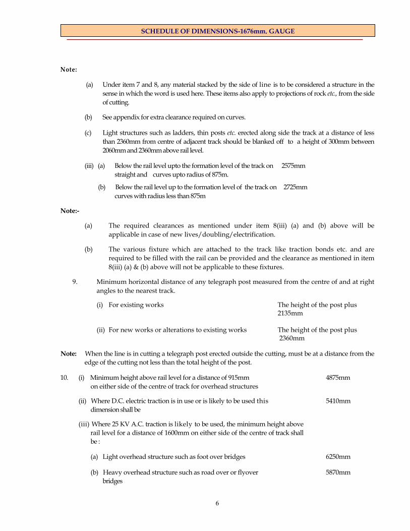
(a) Under item 7 and 8, any material stacked by the side of line is to be considered a structure in the sense in which the word is used here. These items also apply to projections of rock etc., from the side of cutting.
(b) See appendix for extra clearance required on curves.
(c) Light structures such as ladders, thin posts etc. erected along side the track at a distance of less than 2360mm from centre of adjacent track should be blanked off to a height of 300mm between 2060mm and 2360mm above rail level.
(iii) (a) Below the rail level upto the formation level of the track on 2575mm straight and curves upto radius of 875m.
(b) Below the rail level up to the formation level of the track on 2725mm curves with radius less than 875m
Note:-
(a) The required clearances as mentioned under item 8(iii) (a) and (b) above will be applicable in case of new lives/doubling/electrification.
(b) The various fixture which are attached to the track like traction bonds etc. and are required to be filled with the rail can be provided and the clearance as mentioned in item 8(iii) (a) & (b) above will not be applicable to these fixtures.
9. Minimum horizontal distance of any telegraph post measured from the centre of and at right angles to the nearest track.
(i) For existing works The height of the post plus 2135mm (ii) For new works or alterations to existing works The height of the post plus
2360mm
Note: When the line is in cutting a telegraph post erected outside the cutting, must be at a distance from the edge of the cutting not less than the total height of the post.
10. (i) Minimum height above rail level for a distance of 915mm 4875mm on either side of the centre of track for overhead structures
(ii) Where D.C. electric traction is in use or is likely to be used this 5410mm dimension shall be
(iii) Where 25 KV A.C. traction is likely to be used, the minimum height above rail level for a distance of 1600mm on either side of the centre of track shall be :
(a) Light overhead structure such as foot over bridges 6250mm
(b) Heavy overhead structure such as road over or flyover 5870mm bridges
7
SCHEDULE OF DIMENSIONS-1676mm, GAUGE
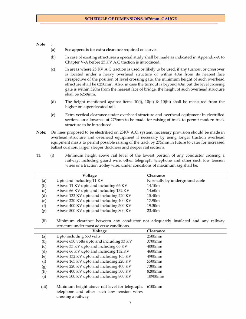
Note : (a) See appendix for extra clearance required on curves.
(b) In case of existing structures a special study shall be made as indicated in Appendix-A to Chapter V-A before 25 KV A.C traction is introduced.
(c) In areas where 25 KV A.C traction is used or likely to be used, if any turnout or crossover is located under a heavy overhead structure or within 40m from its nearest face irrespective of the position of level crossing gate, the minimum height of such overhead structure shall be 6250mm. Also, in case the turnout is beyond 40m but the level crossing gate is within 520m from the nearest face of bridge, the height of such overhead structure shall be 6250mm.
(d) The height mentioned against items 10(i), 10(ii) & 10(iii) shall be measured from the higher or superelevated rail.
(e) Extra vertical clearance under overhead structure and overhead equipment in electrified sections an allowance of 275mm to be made for raising of track to permit modern track structure to be introduced.
Note: On lines proposed to be electrified on 25KV A.C. system, necessary provision should be made in overhead structure and overhead equipment if necessary by using longer traction overhead equipment masts to permit possible raising of the track by 275mm in future to cater for increased ballast cushion, larger sleeper thickness and deeper rail sections.
11. (i) Minimum height above rail level of the lowest portion of any conductor crossing a railway, including guard wire, other telegraph, telephone and other such low tension wires or a traction trolley wire, under conditions of maximum sag shall be:
Voltage Clearance
(a) Upto and including 11 KV Normally by underground cable (b) Above 11 KV upto and including 66 KV 14.10m (c) Above 66 KV upto and including 132 KV 14.60m (d) Above 132 KV upto and including 220 KV 15.40m (e) Above 220 KV upto and including 400 KV 17.90m (f) Above 400 KV upto and including 500 KV 19.30m (g) Above 500 KV upto and including 800 KV 23.40m
(ii) Minimum clearance between any conductor not adequately insulated and any railway
structure under most adverse conditions. Voltage Clearance
(a) Upto including 650 volts 2500mm (b) Above 650 volts upto and including 33 KV 3700mm (c) Above 33 KV upto and including 66 KV 4000mm (d) Above 66 KV upto and including 132 KV 4600mm (e) Above 132 KV upto and including 165 KV 4900mm (f) Above 165 KV upto and including 220 KV 5500mm (g) Above 220 KV upto and including 400 KV 7300mm (h) Above 400 KV upto and including 500 KV 8200mm (i) Above 500 KV upto and including 800 KV 10900mm
(iii) Minimum height above rail level for telegraph, telephone and other such low tension wires crossing a railway
6100mm
8
SCHEDULE OF DIMENSIONS-1676mm, GAUGE
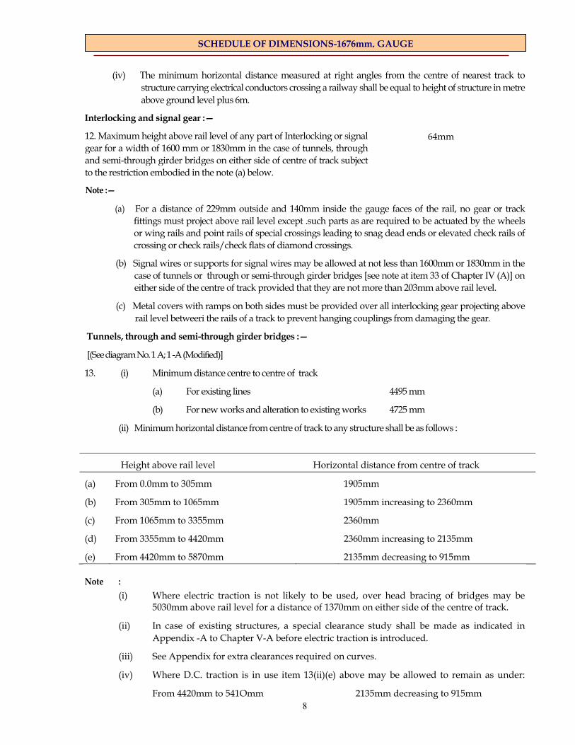
(iv) The minimum horizontal distance measured at right angles from the centre of nearest track to structure carrying electrical conductors crossing a railway shall be equal to height of structure in metre above ground level plus 6m.
Interlocking and signal gear :—
12. Maximum height above rail level of any part of Interlocking or signal gear for a width of 1600 mm or 1830mm in the case of tunnels, through and semi-through girder bridges on either side of centre of track subject to the restriction embodied in the note (a) below.
Note :—
(a) For a distance of 229mm outside and 140mm inside the gauge faces of the rail, no gear or track fittings must project above rail level except .such parts as are required to be actuated by the wheels or wing rails and point rails of special crossings leading to snag dead ends or elevated check rails of crossing or check rails/check flats of diamond crossings.
(b) Signal wires or supports for signal wires may be allowed at not less than 1600mm or 1830mm in the case of tunnels or through or semi-through girder bridges [see note at item 33 of Chapter IV (A)] on either side of the centre of track provided that they are not more than 203mm above rail level.
(c) Metal covers with ramps on both sides must be provided over all interlocking gear projecting above rail level betweeri the rails of a track to prevent hanging couplings from damaging the gear.
Tunnels, through and semi-through girder bridges :—
[(See diagram No. 1 A; 1 -A (Modified)]
13. (i) Minimum distance centre to centre of track
(a) For existing lines 4495 mm
(b) For new works and alteration to existing works 4725 mm
(ii) Minimum horizontal distance from centre of track to any structure shall be as follows :
Height above rail level Horizontal distance from centre of track
(a) From 0.0mm to 305mm 1905mm
(b) From 305mm to 1065mm 1905mm increasing to 2360mm
(c) From 1065mm to 3355mm 2360mm
(d) From 3355mm to 4420mm 2360mm increasing to 2135mm
(e) From 4420mm to 5870mm 2135mm decreasing to 915mm Note :
(i) Where electric traction is not likely to be used, over head bracing of bridges may be 5030mm above rail level for a distance of 1370mm on either side of the centre of track.
(ii) In case of existing structures, a special clearance study shall be made as indicated in Appendix -A to Chapter V-A before electric traction is introduced.
(iii) See Appendix for extra clearances required on curves.
(iv) Where D.C. traction is in use item 13(ii)(e) above may be allowed to remain as under:
From 4420mm to 541Omm 2135mm decreasing to 915mm
64mm
9
SCHEDULE OF DIMENSIONS-1676mm, GAUGE
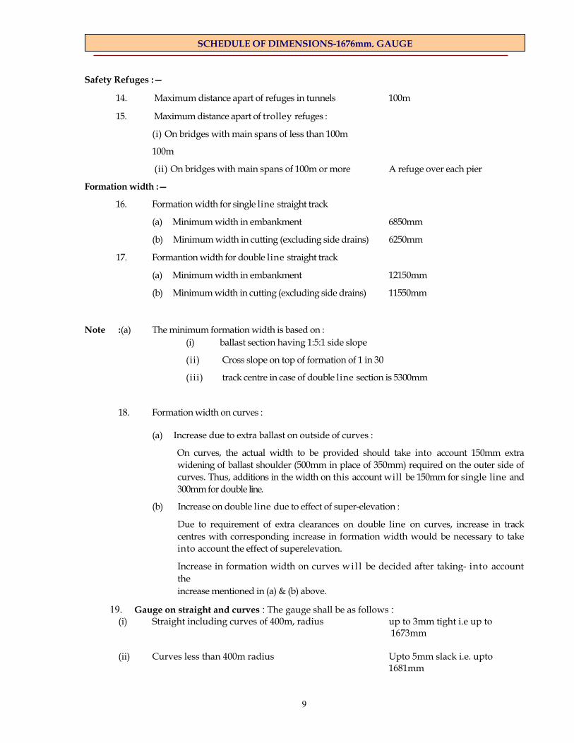
Safety Refuges :—
14. Maximum distance apart of refuges in tunnels 100m
15. Maximum distance apart of trolley refuges :
(i) On bridges with main spans of less than 100m
100m
(ii) On bridges with main spans of 100m or more A refuge over each pier
Formation width :—
16. Formation width for single line straight track
(a) Minimum width in embankment 6850mm
(b) Minimum width in cutting (excluding side drains) 6250mm
17. Formantion width for double line straight track
(a) Minimum width in embankment 12150mm
(b) Minimum width in cutting (excluding side drains) 11550mm
Note :(a) The minimum formation width is based on : (i) ballast section having 1:5:1 side slope
(ii) Cross slope on top of formation of 1 in 30
(iii) track centre in case of double line section is 5300mm
18. Formation width on curves :
(a) Increase due to extra ballast on outside of curves :
On curves, the actual width to be provided should take into account 150mm extra widening of ballast shoulder (500mm in place of 350mm) required on the outer side of curves. Thus, additions in the width on this account will be 150mm for single line and 300mm for double line.
(b) Increase on double line due to effect of super-elevation :
Due to requirement of extra clearances on double line on curves, increase in track centres with corresponding increase in formation width would be necessary to take into account the effect of superelevation.
Increase in formation width on curves wi l l be decided after taking- into account the increase mentioned in (a) & (b) above.
19. Gauge on straight and curves : The gauge shall be as follows : (i) Straight including curves of 400m, radius up to 3mm tight i.e up to
1673mm
(ii) Curves less than 400m radius Upto 5mm slack i.e. upto 1681mm
10
SCHEDULE OF DIMENSIONS-1676mm, GAUGE
CHAPTER II - STATION YARDS (See Diagram No. 2)
Note :
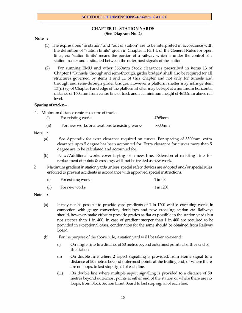
(1) The expressions "in station" and "out of station" are to be interpreted in accordance with the definition of "station limits" given in Chapter I, Part I, of the General Rules for open lines, viz "station limits" means the portion of a railway which is under the control of a station master and is situated between the outermost signals of the station.
(2) For running EMU and other 3660mm Stock clearances prescribed in items 13 of Chapter I "Tunnels, through and semi-through, girder bridges" shall also be required for all structures governed by items 1 and 11 of this chapter and not only for tunnels and through and semi-through girder bridges. However a platform shelter may infringe item 13(ii) (e) of Chapter I and edge of the platform shelter may be kept at a minimum horizontal distance of 1600mm from centre line of track and at a minimum height of 461Omm above rail level.
Spacing of tracks:—
1. Minimum distance centre to centre of tracks. (i) For existing works 4265mm
(ii) For new works or alterations to existing works 5300mm
Note :
(a) See Appendix for extra clearance required on curves. For spacing of 5300mm, extra clearance upto 5 degree has been accounted for. Extra clearance for curves more than 5 degree are to be calculated and accounted for.
(b) New/Additional works cover laying of a new line. Extension of existing line for replacement of points & crossings will not be treated as new work.
2 Maximum gradient in station yards unless special safety devices are adopted and/or special rules enforced to prevent accidents in accordance with approved special instructions.
(i) For existing works 1 in 400
(ii) For new works 1 in 1200
Note :
(a) It may not be possible to provide yard gradients of 1 in 1200 while executing works in connection with gauge conversion, doublings and new crossing station etc. Railways should, however, make effort to provide grades as flat as possible in the station yards but not steeper than 1 in 400. In case of gradient steeper than 1 in 400 are required to be provided in exceptional cases, condonation for the same should be obtained from Railway Board.
(b) For the purpose of the above rule, a station yard will be taken to extend :
(i) On single line to a distance of 50 metres beyond outermost points at either end of the station.
(ii) On double line where 2 aspect signalling is provided, from Home signal to a distance of 50 metres beyond outermost points at the trailing end, or where there are no loops, to last stop signal of each line.
(iii) On double line where multiple aspect signalling is provided to a distance of 50 metres beyond outermost points at either end of the station or where there are no loops, from Block Section Limit Board to last stop signal of each line.
11
SCHEDULE OF DIMENSIONS-1676mm, GAUGE
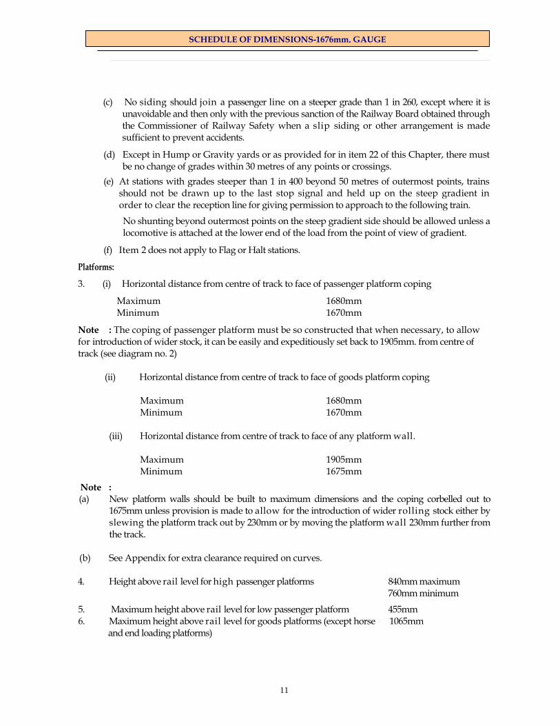
(c) No siding should join a passenger line on a steeper grade than 1 in 260, except where it is
unavoidable and then only with the previous sanction of the Railway Board obtained through the Commissioner of Railway Safety when a slip siding or other arrangement is made sufficient to prevent accidents.
(d) Except in Hump or Gravity yards or as provided for in item 22 of this Chapter, there must be no change of grades within 30 metres of any points or crossings.
(e) At stations with grades steeper than 1 in 400 beyond 50 metres of outermost points, trains should not be drawn up to the last stop signal and held up on the steep gradient in order to clear the reception line for giving permission to approach to the following train.
No shunting beyond outermost points on the steep gradient side should be allowed unless a locomotive is attached at the lower end of the load from the point of view of gradient.
(f) Item 2 does not apply to Flag or Halt stations.
Platforms:
3. (i) Horizontal distance from centre of track to face of passenger platform coping
Maximum 1680mm Minimum 1670mm
Note : The coping of passenger platform must be so constructed that when necessary, to allow for introduction of wider stock, it can be easily and expeditiously set back to 1905mm. from centre of track (see diagram no. 2)
(ii) Horizontal distance from centre of track to face of goods platform coping Maximum 1680mm Minimum 1670mm (iii) Horizontal distance from centre of track to face of any platform wall. Maximum 1905mm Minimum 1675mm
Note : (a) New platform walls should be built to maximum dimensions and the coping corbelled out to
1675mm unless provision is made to allow for the introduction of wider rolling stock either by slewing the platform track out by 230mm or by moving the platform wall 230mm further from the track.
(b) See Appendix for extra clearance required on curves. 4. Height above rail level for high passenger platforms 840mm maximum 760mm minimum
5. Maximum height above rail level for low passenger platform 455mm 6. Maximum height above rail level for goods platforms (except horse 1065mm
and end loading platforms)
12
SCHEDULE OF DIMENSIONS-1676mm, GAUGE
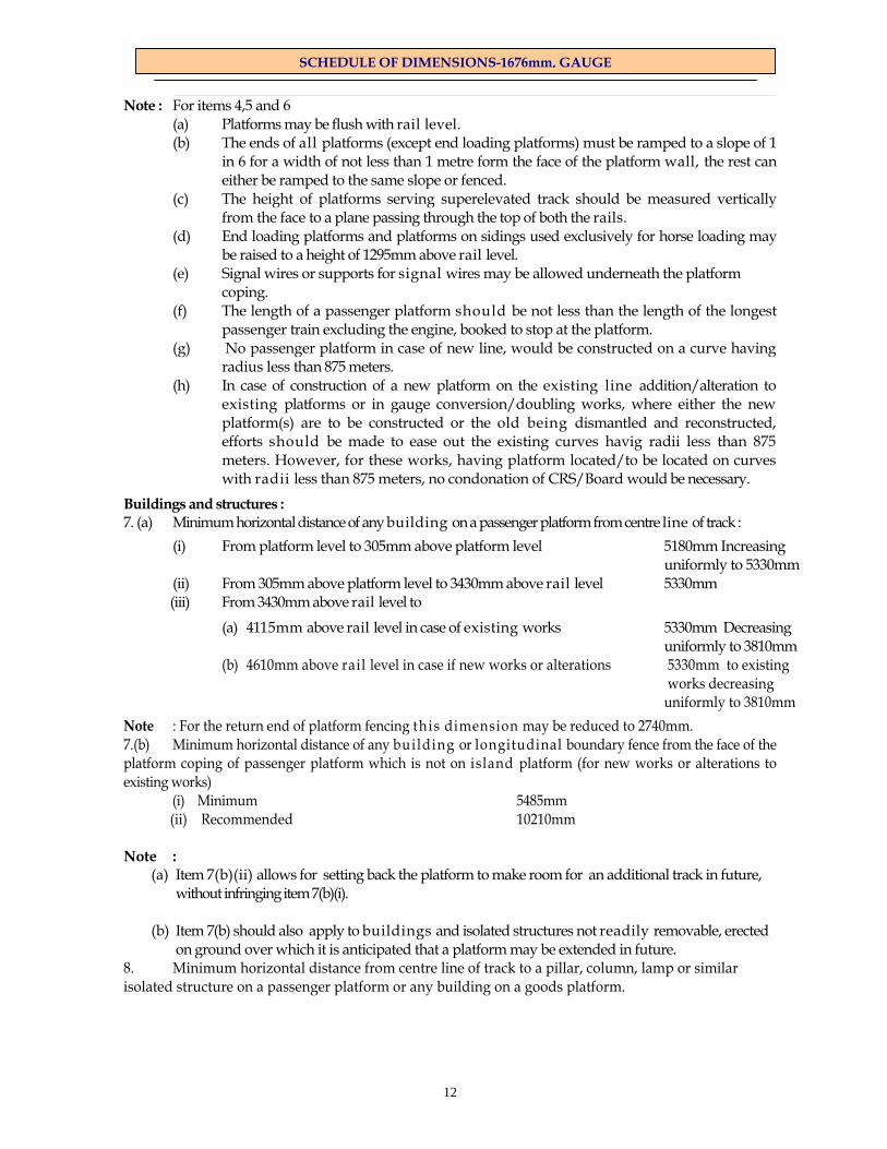
Note : For items 4,5 and 6 (a) Platforms may be flush with rail level. (b) The ends of all platforms (except end loading platforms) must be ramped to a slope of 1
in 6 for a width of not less than 1 metre form the face of the platform wall, the rest can either be ramped to the same slope or fenced.
(c) The height of platforms serving superelevated track should be measured vertically from the face to a plane passing through the top of both the rails.
(d) End loading platforms and platforms on sidings used exclusively for horse loading may be raised to a height of 1295mm above rail level.
(e) Signal wires or supports for signal wires may be allowed underneath the platform coping.
(f) The length of a passenger platform should be not less than the length of the longest passenger train excluding the engine, booked to stop at the platform.
(g) No passenger platform in case of new line, would be constructed on a curve having radius less than 875 meters.
(h) In case of construction of a new platform on the existing line addition/alteration to existing platforms or in gauge conversion/doubling works, where either the new platform(s) are to be constructed or the old being dismantled and reconstructed, efforts should be made to ease out the existing curves havig radii less than 875 meters. However, for these works, having platform located/to be located on curves with radii less than 875 meters, no condonation of CRS/Board would be necessary.
Buildings and structures : 7. (a) Minimum horizontal distance of any building on a passenger platform from centre line of track :
(i) From platform level to 305mm above platform level 5180mm Increasing uniformly to 5330mm (ii) From 305mm above platform level to 3430mm above rail level 5330mm (iii) From 3430mm above rail level to
(a) 4115mm above rail level in case of existing works 5330mm Decreasing uniformly to 3810mm
(b) 4610mm above rail level in case if new works or alterations 5330mm to existing works decreasing
uniformly to 3810mm
Note : For the return end of platform fencing th is dimension may be reduced to 2740mm. 7.(b) Minimum horizontal distance of any building or longitudinal boundary fence from the face of the platform coping of passenger platform which is not on island platform (for new works or alterations to existing works)
(i) Minimum 5485mm (ii) Recommended 10210mm
Note :
(a) Item 7(b)(ii) allows for setting back the platform to make room for an additional track in future, without infringing item 7(b)(i).
(b) Item 7(b) should also apply to buildings and isolated structures not readily removable, erected
on ground over which it is anticipated that a platform may be extended in future. 8. Minimum horizontal distance from centre line of track to a pillar, column, lamp or similar isolated structure on a passenger platform or any building on a goods platform.
13
SCHEDULE OF DIMENSIONS-1676mm, GAUGE
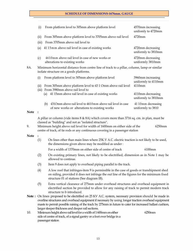
(i) From platform level to 305mm above platform level 4570mm increasing
unifomly to 4720mm
(ii) From 305mm above platform level to 3705mm above rail level 4720mm
(iii) From 3705mm above rail level to
(a) 41 15 m m above rail level in case of existing works 4720mm decreasing uniformly to 3810mm
(c) 4610mm above rail level in case of new works or 4720mm decreasing alterations to existing works uniformly 3810mm
8A. Minimum horizontal distance from centre line of track to a pillar, column, lamp or similar isolate structure on a goods platforms.
(i) From platform level to 305mm above platform level 3960mm increasing uniformly to 4110mm (ii) From 305mm above platform level to 43 1 Omm above rail level 4110mm (iii) From 3980mm above rail level to
(a) 41 15mm above rail level in case of existing works 4110mm decreasing uniformly to 3810mm
(b) 431Omm above rail level to 4610mm above rail level in case 41 10mm decreasing of new works or alterations to existing works uniformly to 3810
Note :
A pillar or column (vide items 8 & 8A) which covers more than 3716 sq. cm. in plan, must be classed as "building" and not as "isolated structure".
9. Minimum height above rail level for width of 1600mm on either side of the 6250mm centre of track, of tie rods or any continuous covering in a passenger station
Note : (1) On lines other than main lines where 25K.V A.C. electric traction is not likely to be used,
the dimensions given above may be modified as under :
For a width of 1370mm on either side of centre of track 6100mm
(2) On existing primary lines, not likely to be electrified, dimension as in Note 1 may be allowed to continue.
(3) Item 9 does not apply to overhead piping parallel to the track.
(4) A low roof that infringes-item 9 is permissible in the case of goods or transhipment shed on siding, provided it does not infringe the out line of the figures for the minimum fixed structure 01 of stations (See diagram IB).
(5) Extra vertical clearance of 275mm under overhead structures and overhead equipment in electrified section be provided to allow for any raising of track to permit modern track structure to b introduced.
Note : On lines proposed to be electrified on 25 KV A.C. system, necessary provision should be made in overline structures and overhead equipment if necessary by using longer traction overhead equipment masts to permit possible raising of the track by 275mm in future to cater for increased ballast cushion, larger sleeper thickness and deeper rail sections.
10. Minimum height above rail level for a width of 1 600mm on either 6250mm side of centre of track, of a signal gantry or a foot over bridge in a passenger station

14
SCHEDULE OF DIMENSIONS-1676mm, GAUGE
Note :
(a) Where D.C. traction is in use or likely to be used, this minimum height should be 54 1Omm. (b) On secondary lines where electric traction is not likely to be introduced, this m i n i m u m height
may be 4875mm. This also applies to overhead piping arrangements parallel to track wherever provided, which shall necessarily be changed over to the ground hydrants when the section is electrified.
11. Minimum, horizontal distance from centre of track to any structure : (A) For existing works :
(i) From rail level to 305mm above rail level 1675mm (ii) From 305mm above rail level to 3355mm above rail level 2135mm (iii) From 3355mm above rail level to 41 15mm above rail level 2135mm decreasing to 1980mm (iv) From 41 15mm to 6250mm above rail levelon main line 1600mm (v) Below the rail level upto the formation level of the 2575mm
track on straight and curves upto radius of 875m. (vi) Below the rail level upto the formation level of the track on curves with radius less than 875 in. 2725mm
Note : (a) See appendix for extra clearances required on curves (b) On lines other than main lines or existing main lines where electric traction is
not likely to be introduced, the horizontal distance of 1375mm from 4115mm to 6100mm above rail level may be allowed to continue.
(c) The clearance mentioned above in item (v) and (vi) will be applicable only in new yards/electrification works. The various fixtures which are attached to the track like lock bar, point machine, 'traction bonds, point and signal rodding etc. and are required to be fitted with the rail can be provided and the clearance as mentioned in item 11 (v) and 11 (vi) above will not be applicable to these items.
(B) In case of new works or alteration to existing works (i) From rail level to 305mm above rail level 1905mm (ii) From 305mm above rail level to 1065mm 1905mm increasing to 2360mm
(iii) From 1065mm above rail level to 3355mm 2360mm (iv) From 3355mm above rail level to 4420mm 2360mm decreasing
to 2135mm (v) From 4420mm above rail level to 4610mm 2135mm decreasing
to 1980mm (vi) From 4610mm above rail level to 6250mm 1600mm
Note : See Appendix for extra clearances on curves Points and crossings : 12. Maximum clearance of check rail opposite nose of crossing 48mm Note :
(a) In case of turnouts laid with 1673mm gauge, the clearance shall be 45mm instead of 48mm
(b) In the obtuse crossing of diamond crossings, the clearances at the throat of the obtuse crossing shall be 41mm

15
SCHEDULE OF DIMENSIONS-1676mm, GAUGE
13. Minimum clearance of check rail opposite nose of crossing 44mm Note :
(a) In case of turnouts laid with 1673mm gauge, the clearance shall be 41mm instead of 44mm
(b) In the obtuse crossing of diamond crossings the clearance at the throat of the obtuse crossing shall be 41mm
14. Maximum clearance of wing rail at nose of crossing 48mm Note : In case of turnouts laid with 1673mm gauge, the clearance shall be 41mm instead of 44mm. 15. Minimum clearance of wing rail at nose of crossing 44mm Note : In case of turn outs laid with 1673mm gauge, the clearance shall be 41mm instead of 44mm. 16. Minimum clearance between toe of open switch and stock rail (i) For existing works 95mm (ii) For new works or alteration to existing works 115mm Note :
The clearance can be increased upto 160mm in curved switches in order to obtain adequate clearance between gauge face of stock rail and back face of tongue rail.
17. Minimum radius of curvature for slip points, turnouts of crossover roads 218 metres (8 degree) Note : In special cases mentioned below this may be reduced to not less than the minimum of
(i) 213m radius in case of 1 in 8.5 BG turnouts with 6.4m over riding switch, and (ii) 175m radius in case of 1 in 8.5 scissors crossing to allow for sufficient straight over
the diamond crossing between crossovers. 18. Minimum angles of crossing (ordinary) 1 in 16 Note :
Crossings as flat as 1 in 20 will usually be sanctioned if recommended by the Commissioner of Railway Safety.
19. Diamond crossings not to be flatter than 1 in 8.5 Note :
Diamond Crossings as flat as 1 in 10 will usually be sanctioned if recommended by the Commissioner of Railway Safety.
20. Minimum length of tongue rail 3660mm
21. Minimum length of train protection, point locking or fouling treadle bar 12800mm Note : There must be no change of superelevation (of outer over inner rail) between points 18m out side toe of switch rail and nose of crossing respectively, except in the case of special crossings leading to snag dead-ends or under circumstances as provided for in item-22.

16
SCHEDULE OF DIMENSIONS-1676mm, GAUGE
22. Superelevation and speed in stations on curves with turnouts of contrary and similar flexure :
Main line : Subject to the permissible run through speed, based on the standard of. interlocking, the equilibirium superelevation, calculated for the speed of the fastest train, may be reduced by a maximum amount of 75mm without reducing the speed on the mainline.
Turnouts:
(i) Curves of contrary flexure :—
The equilibrium superelevation in millimeters should be calculated by the formula
11860 C = ---------------- R
Where R = Radius of turnout in metres
The permissible negative superelevation on the turnout (which is also the actual superelevation of the main line) may then be made as (75-C)mm.
(ii) Curves of similar flexure :—
The question of reduction or otherwise of superelevation on the mainline must necessarily be determined by the administration concerned. In the case of a reverse curve close behind the crossing of the turnouts, the superelevation may be run out at the maximum of 1 mm in 360mm.
Length of sidings :
23. Minimum clear available length of one siding at any station where it is intended to cross trains :
(i) At a non-watering station-7 percent longer than the longest train permitted to run on the section
(ii) At a watering station such that when the train engine is standing (and taking water), at the water column the rear of the longest train permitted to run on the section shall be at least 15 metres clear of the fouling mark in rear and such that when a second assisting engine is standing (and taking water) at a water column the leading engine is clear of the fouling mark in front.
(iii) Although it may not be necessary till traffic develops to provide sidings for the largest possible train loads, land should be acquired for them and no building, level crossings or other obstructions should be permitted that will interfere with one crossing siding being lengthened to the following dimensions:
On sections of the railway where the ruling gradients is
Minimum clear available length of one siding
1 in 500 or flatter
770metres
Between 1 in 500 and 1 in 300 610metres
Between 1 in 300 and 1 in 100 550metres
Between 1 in 100 and 1 in 50 490metres
Steeper than 1 in 50 370metres

17
SCHEDULE OF DIMENSIONS-1676mm, GAUGE
CHAPTER III - Workshops and Station Machinery
Water tanks and water cranes :
1. (a) Minimum height above rail level for discharge orifice of water crane 3660mm
(b) Distance from centre of track to face of tank house less than 60 metres beyond the end of a passenger platform.
(i) Minimum 7165mm
(ii) Recommended 11890mm Note :
(a) Item l(b) need not be observed in the case of small subsidiary or relay tanks which can easily be removed back to provide room for an extension of the yard.
(b) Item l(b)(i) allows for the extension of the platform and item l(b)(i i ) allows for the laying of an additional track and extending of the platform in future.
(c) Minimum height for bottom of tank above rail level at water column :
(i) For watering engines 7620mm
(ii) For washing engines 12190mm
(d) Minimum total tank capacity at any station 56.5 cu metres or 56825 liters
(e) Minimum internal diameter for piping from tank to water crane 203mm
Workshops and running sheds :
2. Minimum distance from centre to centre of tracks
(i) For existing works 4570mm
(ii) For new works or alterations to existing works
(a) In workshops 4570mm
(b) In running sheds 5260mm
Note :
Where there is a structure between tracks, the distance of centre to centre of tracks is to be increased by the amount of the width of the structure like O.H.E. post etc.
3. Minimum clear distance from centre of track to any isolated structure such as a pillar in :
(i) Workshops
(a) For existing works 2285mm (b) For new works or alterations to existing works 2360mm
18
SCHEDULE OF DIMENSIONS-1676mm, GAUGE
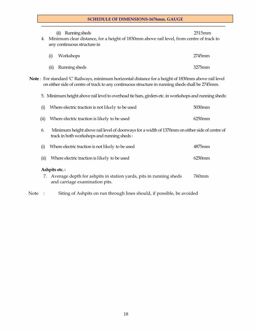
(ii) Running sheds 2515mm 4. Minimum clear distance, for a height of 1830mm above rail level, from centre of track to
any continuous structure in
(i) Workshops 2745mm (ii) Running sheds 3275mm
Note : For standard 'C' Railways, minimum horizontal distance for a height of 1830mm above rail level on either side of centre of track to any continuous structure in running sheds shall be 2745mm.
5. Minimum height above rail level to overhead tie bars, girders etc. in workshops and running sheds: (i) Where electric traction is not likely to be used 5030mm (ii) Where electric traction is likely to be used 6250mm 6. Minimum height above rail level of doorways for a width of 1370mm on either side of centre of
track in both workshops and running sheds :
(i) Where electric traction is not likely to be used 4875mm
(ii) Where electric traction is likely to be used 6250mm
Ashpits etc. : 7. Average depth for ashpits in station yards, pits in running sheds 760mm
and carriage examination pits. Note : Siting of Ashpits on run through lines should, if possible, be avoided
19
SCHEDULE OF DIMENSIONS-1676mm, GAUGE
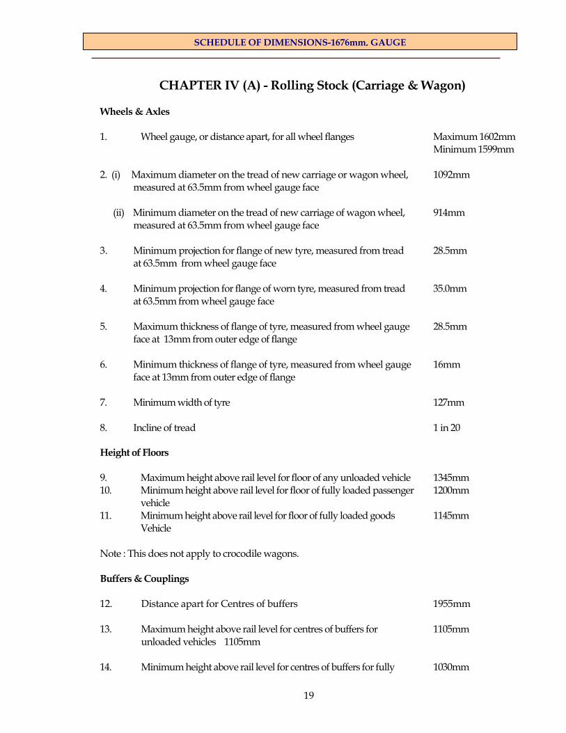
CHAPTER IV (A) - Rolling Stock (Carriage & Wagon)
Wheels & Axles 1. Wheel gauge, or distance apart, for all wheel flanges Maximum 1602mm Minimum 1599mm 2. (i) Maximum diameter on the tread of new carriage or wagon wheel, 1092mm
measured at 63.5mm from wheel gauge face
(ii) Minimum diameter on the tread of new carriage of wagon wheel, 914mm measured at 63.5mm from wheel gauge face
3. Minimum projection for flange of new tyre, measured from tread 28.5mm
at 63.5mm from wheel gauge face
4. Minimum projection for flange of worn tyre, measured from tread 35.0mm at 63.5mm from wheel gauge face
5. Maximum thickness of flange of tyre, measured from wheel gauge 28.5mm face at 13mm from outer edge of flange
6. Minimum thickness of flange of tyre, measured from wheel gauge 16mm face at 13mm from outer edge of flange
7. Minimum width of tyre 127mm 8. Incline of tread 1 in 20 Height of Floors 9. Maximum height above rail level for floor of any unloaded vehicle 1345mm 10. Minimum height above rail level for floor of fully loaded passenger 1200mm vehicle 11. Minimum height above rail level for floor of fully loaded goods 1145mm Vehicle Note : This does not apply to crocodile wagons. Buffers & Couplings 12. Distance apart for Centres of buffers 1955mm 13. Maximum height above rail level for centres of buffers for 1105mm unloaded vehicles 1105mm 14. Minimum height above rail level for centres of buffers for fully 1030mm

20
SCHEDULE OF DIMENSIONS-1676mm, GAUGE
loaded vehicles Wheel Base & Length of Vehicles 15. Maximum rigid wheel base for four wheeled vehicles 6100mm 16. Minimum distance apart of bogie centres for bogie vehicles 5400mm 17. Maximum distance apart of bogie centres for bogie vehicles 15241mm 18. (i) Minimum rigid wheel base for bogie truck of any vehicle 1830mm
(ii) Minimum rigid wheel base for bogie truck of passenger vehicle 2440mm
19. Maximum length of body or roof for:
(a) 4-wheeled vehicle 8540mm (b) Bogie vehicles 21340mm
Note : (i) A cornice may project beyond the maximum permissible length of the roof up to 51 mm in
the case of (a) above, beyond each end of the vehicle. (ii) Fittings on the end of a vehicle, such as step iron, vacuum brake piping, electrical
connection vestibule etc., need not be kept within the prescribed maximum permissible lengths for bodies of vehicles, but may project beyond the end of the body to a reasonable extent.
(iii) Maximum length of bogie wagons can be upto 23550mm subject to tapering of the ends in
a manner that the end throw when calculated as per Appendix is same as that for a coach of 21340mm length and within this Schedule of Dimensions.
20. Maximum length over side buffers :
(a) 4-wheeled vehicle 9810mm (b) Bogie vehicles 22300mm
Note: The maximum length over the side buffers for longer coaches as per item 20 above shall be so arranged that the difference between the length over side buffers and the length of body or roof is not less than 460mm.
21. Maximum distance apart between any two adjacent axles 12345mm Maximum Moving Dimensions (See diagram ID) 22. Maximum width over all projections at 102mm above rail level, 2440mm

21
SCHEDULE OF DIMENSIONS-1676mm, GAUGE
when fully loaded 23. Maximum width over all projections, at 305mm above rail level, 3135mm
when fully loaded.
24. Maximum width over all projections from 305mm above rail level, 3135mm to 1082mm above rail level, when fully loaded
25. Maximum width over all projection from 1082mm above rail level, 3135mm to 1170mm above rail level, when fully loaded increasing gradually to 3250mm
26. Maximum width over all projections from 1082mm above rail level, 3250mm when fully loaded to a height of 3380mm when empty
(i) Guttering, side lamps and destination boards may project 76mm on each side beyond the dimensions given above from a height of 2895mm to 3355mm above rail level, upto a maximum over all width of 3402mm.
(ii) Coach number plates may project 25mm on each side beyond the dimension given
above from a height of 2590mm to 2895mm above rail level, upto a maximum over all width of 3300mm.
(iii) Reservation card holders may project 25mm on each side beyond the dimensions
given above from a height of 1750mm to 1980mm above rail level upto a maximum over all width of 3300mm.
(iv) The doors are to be either sliding or opening inwards. Handbolts, door locks,
handles and window bars shall not, however, project beyond the dimensions given against item above.
27. Maximum width over open doors, including all projections for passenger vehicles. 4040mm 28. Maximum width over open doors, including all projections for goods vehicles. 4265mm Note : Doors of horse boxes, brake vans, luggage vans and rising and falling flap doors of
goods wagons are exempted from this rule. 29. Maximum height above rail level for a width of 760mm on either side of the 4265mm
centre of unloaded vehicles. 30. Maximum height above rail level at side of unloaded vehicles. 3735mm Note :
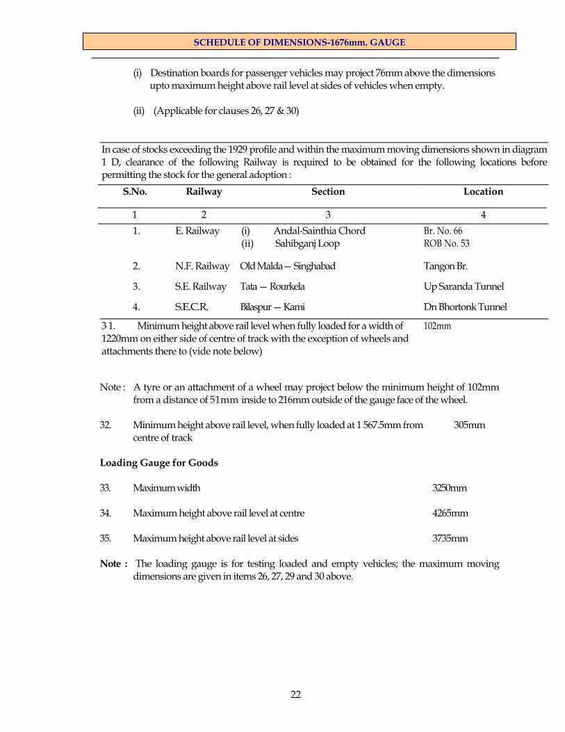
22
SCHEDULE OF DIMENSIONS-1676mm, GAUGE
(i) Destination boards for passenger vehicles may project 76mm above the dimensions upto maximum height above rail level at sides of vehicles when empty.
(ii) (Applicable for clauses 26, 27 & 30)
In case of stocks exceeding the 1929 profile and within the maximum moving dimensions shown in diagram 1 D, clearance of the following Railway is required to be obtained for the following locations before permitting the stock for the general adoption :
S.No.
Railway
Section
Location
1 2 3 4 1.
E. Railway
(i) Andal-Sainthia Chord (ii) Sahibganj Loop
Br. No. 66 ROB No. 53
2.
N.F. Railway
Old Malda— Singhabad
Tangon Br.
3.
S.E. Railway
Tata — Rourkela
Up Saranda Tunnel
4.
S.E.C.R.
Bilaspur — Kami
Dn Bhortonk Tunnel 3 1. Minimum height above rail level when fully loaded for a width of
1220mm on either side of centre of track with the exception of wheels and attachments there to (vide note below)
102mm
Note : A tyre or an attachment of a wheel may project below the minimum height of 102mm
from a distance of 51mm inside to 216mm outside of the gauge face of the wheel. 32. Minimum height above rail level, when fully loaded at 1 567.5mm from 305mm
centre of track
Loading Gauge for Goods 33. Maximum width 3250mm 34. Maximum height above rail level at centre 4265mm 35. Maximum height above rail level at sides 3735mm Note : The loading gauge is for testing loaded and empty vehicles; the maximum moving
dimensions are given in items 26, 27, 29 and 30 above.

23
SCHEDULE OF DIMENSIONS-1676mm, GAUGE
CHAPTER IV (B)
Rolling Stock, 3660mm wide stock Note :
These dimensions shall not be adopted in designs for rolling stock without the special sanction of the Railway Board in each case.
Maximum Future Moving Dimensions : (See diagram No. 1A)
1. Maximum width over all projections: (i) At 102mm above rail level, when fully loaded 2895mm
(ii) At 305mm above rail level, when fully loaded 3505mm
(iii) From 305mm above rail level to 1145mm above rail level 3505mm when fully loaded
(iv) From 1145mm above rail level, when fully loaded to a height 3660mm of 3355mm when empty
(v) At 4265mm above rail level, when empty 3505mm
2. Maximum width over open doors, including all projections, 4495mm for passenger vehicles
3. Maximum width over open doors, including all projections, 4725mm for goods vehicles
Note : Doors of horse boxes, brake vans, luggage vans and rising and falling flap doors of goods wagons are exempted from this rule.
4. Maximum height above rail level for a width of 915mm on either 4725mm side of the centre of unloaded vehicles.
5. Maximum height above rail level at sides of unloaded vehicles 4265mm
6. Minimum height above rail level, when fully loaded for a width 102mm of 1450mm on either side of centre of track, with the exception of wheels and attachments thereto (vide note below)
Note : A tyre or an attachment to a wheel may project below the minimum height of 102mm from a distance of 51mm inside to 216mm outside of the gauge face of the wheel.
7. Minimum height above rail level, when fully loaded at 1755mm 305mm from centre of track
Loading gauge for goods :
8. (i) Maximum width at a height of 3380mm above rail level 3710mm (ii) Maximum width at a height of 4295mm above rail level 3555mm
9. Maximum height above rail level for a width of 915mm on either 4750mm side of the centre of track
10. Maximum height above rail level at sides 4295mm Note: The loading gauge is for testing loaded and empty vehicles, the maximum moving
dimensions are given in items 1 (iv), 4 and 5 above.

24
SCHEDULE OF DIMENSIONS-1676mm, GAUGE
CHAPTER IV(C) Rolling Stock (Locomotive) Wheels and axles :
1. Wheel gauge or distance apart for wheel flanges :
(a) Wheels with thick flanges/wear adopted wheel profile 1596mm
(b) Wheels with standard flanges 1600mm
(c) Wheels with thin flanges 1600mm (d) Wheels without flanges 1600mm (See item 5 for identification of thick/wear adopted, standard & thin flanges)
2. (i) Maximum diameter on the tread of new locomotive carrying 1092mm wheels measured at 63.5mm from wheel gauge face.
(ii) Minimum diameter on the tread of new locomotive carrying 914mm wheels measured at 63.5mm from wheel gauge face.
3. Minimum projection for flange of new tyre measured from tread at 28.5mm 63.5mm from wheel gauge face.
4. Maximum projection for flange of worn tyre measured from tread at 35mm
63.5mm from wheel gauge face. 5. Maximum & minimum thicknesses of tyre flanges measured at 13mm from outer edge of flange :
Max. Min. (a) Thick flanges/wear adopted wheel profile 32mm —
(b) Standard flanges 28mm — (c) Thin flanges 18mm —
Note :
(i) The above values of flange thicknesses are measured from the back face of the tyre. (ii) Minimum size of flange of locomotive tyres shall be determined by condemning profile gauge which
specifies the minimum thickness and the limits of angularity of the flange on the gauge face. 6. Minimum width of tyres:
(a) Locomotive coupled wheels 133mm (b) Locomotive wheels other than coupled 127mm
7. Incline of tread 1 in 20 for all profiles except wear adopted profile for which the tread inclination of 1 in 20 will merge
with radii of the wear adopted profile

25
SCHEDULE OF DIMENSIONS-1676mm, GAUGE
Buffers & Couplings :
8. Distance apart for centres of buffers 1955mm
9. Maximum height above rail level for centres of buffers for empty 1105mm locomotive
10. Minimum height above rail level for centres of buffers when fully 1030mm loaded
Maximum Moving Dimensions : (See diagrams 1 D-the new diagrams introduced by RDSO)
11. Maximum width over all Projections:
(i) At 102mm (min) above rail level, when fully loaded 2440mm
(ii) From 305mm (min.) above rail level to 1082mm above rail level, 3135mm when fully loaded
(iii) From 1082mm above rail level to 1170mm above rail level, 3135mm when fully loaded creasing gradually to 3250mm
(iv) From 1170mm above rail level, when fully loaded, 3250mm to a height of 3735mm when empty
12. Maximum height above rail level for a width of 760mm on either 4265mm side of centre of empty locomotives
13. Maximum height above rail level at sides of empty locomotives 3735mm
Maximum Moving Dimensions for X-CIass locomotives
14. Maximum width over all projections:
(i) At 102mm above rail level, when fully loaded 2440mm
(ii) From 305mm above rail level to 1110mm above rail level, 3135mm when fully loaded in creasing
gradually to 3200mm
(iv) From 1145mm above rail level when fully loaded to a height 3200mm of 3735mm above rail level, when empty
15. Maximum height above rail level for a width of 305mm 4470mm on either side of centre of empty locomotives
16. Maximum height above rail level at sides of empty locomotives 3735mm
17. Minimum height above rail level when fully loaded for a width 102mm of 1220mm on either side of centre of track with the exception of wheels and attachments thereto (vide note below)
Note : A tyre or an attachment to a wheel or sand pipes in line with the wheel may project below the minimum height of 102mm from a distance of 51mm insides to 216mm outside of the gauge face of the wheel.
18. Minimum height above rail level when fully loaded at 1525mm from 305mm centre of track

26
SCHEDULE OF DIMENSIONS-1676mm, GAUGE
CHAPTER V - ELECTRIC TRACTION (Direct Current)
Note: Wherever electric traction, employing overhead conductor wires, is in use strict orders must be issued prohibiting any one from getting on the roofs of vehicles until the current in the overhead conductors has been switched off and the conductors themselves have been earthed.
1. Minimum height from rail level to the underside of live conductor wire:
(i) Under bridges and tunnels 5030mm (ii) In the open 5335 mm (iii) In running and carriage sheds 5790 mm (iv) At level crossing 5485 mm
Note : The height prescribed in item 1 (iv) applies also to tramway trolley wires crossing the railway.
2. Maximum height from rail level to the underside of live 5790mm contact wire except in running and carriage sheds
Note: In the case of running and carriage sheds, the maximum height of the contact wire will be determined in each case based on the operating range of the pantograph and the permissible electrical clearances required inside the sheds.
3. Maximum variation of live conductor wire on either side of the central line of
track: (i) On straight track 230mm (ii) On curves (on the inside of the curve) 380mm
4. Minimum distance between live conductor wire and 130mm any structure
5. Maximum width of pantograph collector 2030mm
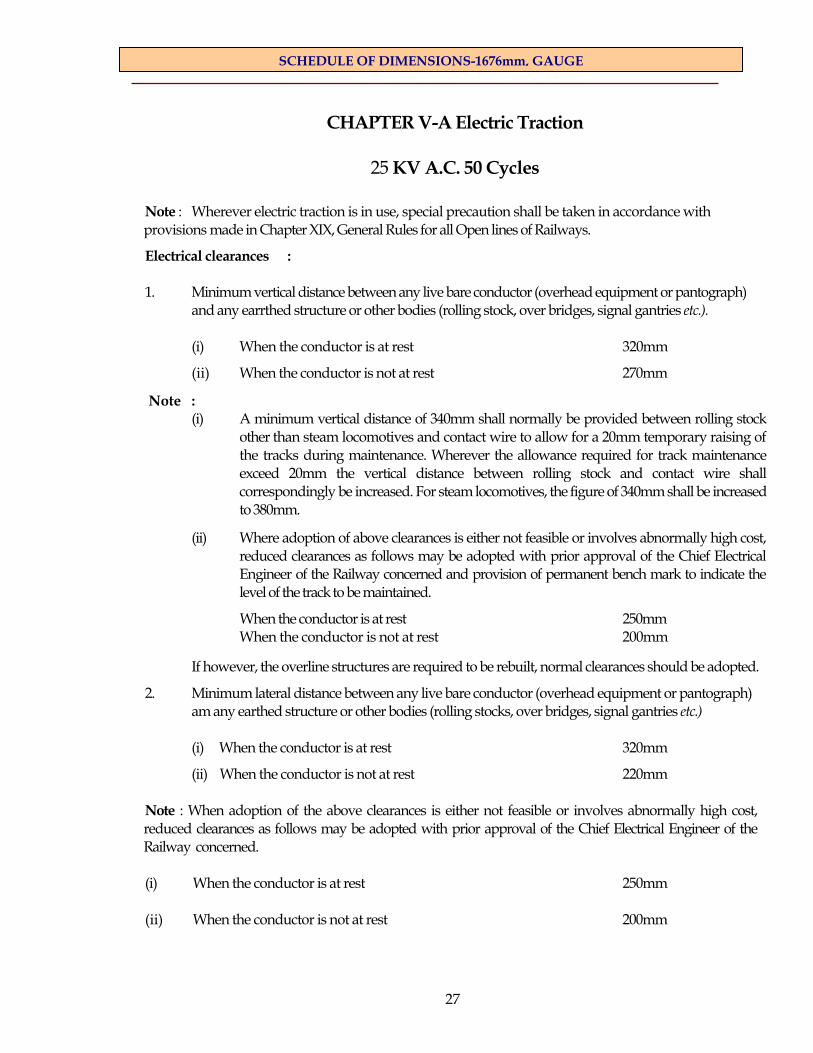
27
SCHEDULE OF DIMENSIONS-1676mm, GAUGE
CHAPTER V-A Electric Traction
25 KV A.C. 50 Cycles
Note : Wherever electric traction is in use, special precaution shall be taken in accordance with provisions made in Chapter XIX, General Rules for all Open lines of Railways.
Electrical clearances : 1. Minimum vertical distance between any live bare conductor (overhead equipment or pantograph)
and any earrthed structure or other bodies (rolling stock, over bridges, signal gantries etc.).
(i) When the conductor is at rest 320mm
(ii) When the conductor is not at rest 270mm Note :
(i) A minimum vertical distance of 340mm shall normally be provided between rolling stock other than steam locomotives and contact wire to allow for a 20mm temporary raising of the tracks during maintenance. Wherever the allowance required for track maintenance exceed 20mm the vertical distance between rolling stock and contact wire shall correspondingly be increased. For steam locomotives, the figure of 340mm shall be increased to 380mm.
(ii) Where adoption of above clearances is either not feasible or involves abnormally high cost, reduced clearances as follows may be adopted with prior approval of the Chief Electrical Engineer of the Railway concerned and provision of permanent bench mark to indicate the level of the track to be maintained.
When the conductor is at rest 250mm When the conductor is not at rest 200mm
If however, the overline structures are required to be rebuilt, normal clearances should be adopted.
2. Minimum lateral distance between any live bare conductor (overhead equipment or pantograph) am any earthed structure or other bodies (rolling stocks, over bridges, signal gantries etc.)
(i) When the conductor is at rest 320mm
(ii) When the conductor is not at rest 220mm Note : When adoption of the above clearances is either not feasible or involves abnormally high cost, reduced clearances as follows may be adopted with prior approval of the Chief Electrical Engineer of the Railway concerned. (i) When the conductor is at rest 250mm (ii) When the conductor is not at rest 200mm

28
SCHEDULE OF DIMENSIONS-1676mm, GAUGE
3. Height of contact wire : Minimum height from rail level to the underside of live conductor:
(i) Under bridges and in tunnels 4.80m Note : Para 4(a) Appendix A to Chapter V-A explains the basis of this dimension. (ii) In the open 5.50m
(iii)At level crossings 5.50m (iv) In running and carriage sheds 5.80m
Note :
(a) (i) In cases where it is proposed to allow only locomotives or stocks not higher than ,4.27m, the minimum height of contact wire specified under item 3(i) may be reduced to 4.65m. A board showing this restriction and specifying locomotives or stocks not permitted to ply normally on such sections should be exhibited at the entrance to the same.
(ii) In case reduced clearances as indicated in Note(ii) under item 1 are adopted, the
minimum height of contact wire as provided in Note (a)(i) above upto 4.65m may be further reduced to 4.58m. The board as adopted in note (a)(i) should also indicate clearly the special reduced clearances having been adopted at the location.
(b) For movement of over dimensional consignments the height specified under 3(i) above, shall
be increased by the difference between the height of the consignment contemplated and 4.41 m. In case such an over dimensional consignment is moved at speeds not exceeding 15 Km/h and is also specially escorted by authorized railway staff, the desired height of contact wire may be reduced by 50mm.
(c) On curves, all vertical distance specified in item 3 above, shall be measured above the level
of the inner rail, increased by half the superelevation.
4. Maximum variation of the live conductor wire on either side of the centre line of track under static conditions.
(i) On straight track 200mm (ii) On curves 300mm
Note: These limits would not apply to special locations like insulated overlaps and out of run wires. 5. Maximum width of pantograph collector 1800mm Note : A tolerance of plus 10mm on maximum width specified is permissible to accommodate variation in manufacture and mounting with respect to the centre line of vehicle.
29
SCHEDULE OF DIMENSIONS-1676mm, GAUGE
SCHEDULE – II
Existing infringements of Schedule I which may be permitted to continue on existing 1676mm gauge Railways :
The following infringements of the dimensions prescribed in Schedule I may, subject to such restrictions of speed as are considered necessary, be permitted on existing railways (See diagram No. 3) it being understood that when structures are altered they will be rebuilt to comply with Schedule I, except in case of structures falling under item 7.
Dimensions marked (a) refer to the requirements for 3250mm wide stick [Chapter IV(A) of Schedule I], and those marked (b) refer to the requirements for 3660mm wide and 4725mm high stock (Chapter IV(B) of Schedule I)
1. (a) Maximum distance centre to centre of tracks 3660mm
(b) Minimum distance centre to centre of tracks 4040mm
2. (a) Minimum clear horizontal distance from centre of track to 1675mm any fixed structure from rail level to 1 065mm above rail level.
(b) Minimum clear horizontal distance from centre of track to any fixed 1905mm structure from rail level to 1065mm above rail level
3. (a) Minimum clear horizontal distance from centre of track to any fixed 1980mm structure from 1065mm above rail level to 3505mm above rail level.
(b) Minimum clear horizontal distance from centre of track to any fixed 21 35mm structure from 1 065mm above rail level to 3355mm above rail level.
4. (a) Minimum clear horizontal distance from centre of track at 4265mm 2055mm above rail level.
5. (a) Minimum clear height above rail level for a distance of 305mm on 4420mm either side of centre of track.
(b) Minimum clear height above rail level for a distance of 915mm on 5030mm either side of centre of track.
Note :
(i) Items 2(a), 3(a), 3(b) and 4(a) refer to structures outside station yards only.
(ii) Where speed is restricted to 16 km/h, the minimum clear horizontal distance under 4(a) may be reduced to 1980mm. (iii) Where, as on girder bridges, ashpits, etc., the structure is not likely to be out of plumb
and the superelevation (or level of rails) does not vary and where the speed is restricted to 16km/h, the above dimensions may be reduced to :
3580mm for l(a), 3960mm for
l(b), 1 905mm for 3(a), 2055mm for 3(b), 1980mm for 4(a), 4265mm for 5(a), 4875mm for 5(b)

30
SCHEDULE OF DIMENSIONS-1676mm, GAUGE
(iv) To the horizontal distance given in 1 to 5 must be added the extra allowance for curves (See Appendix). Where existing structures do not permit of these allowances being given, they may be reduced by limiting the superelevation to be allowed for outer over inner rail. When this is done a notice board should be erected against the structure, stating the maximum permissible superelevation.
6. The minimum permissible clearances in existing tunnels and girder bridges shall be:
(i) Under any circumstances and subject to any restriction of speed which it may be considered necessary to impose:
In tunnels
(See Diagram No.3) On grider bridges
At ‘A’ 229mm 229mm at top of sides of vehicles ‘B’ 305mm 229mm at side of vehicles ‘C’ 380mm 305mm between moving trains ‘D’ 229mm 152mm above vehicles (ii) For unrestricted speeds: In tunnels On Girder Bridges At ‘A’ 380mm 229mm at top of the sides of vehicles ‘B’ 535mm 455mm at sides of vehicles ‘C’ 610mm 535mm between moving trains ‘D’ 305mm 229mm above vehicles
Where doors opening inwards or of the recessed or sliding type are provided the minimum clearances in tunnels and bridges may be reduced to 380mm, at 'B' and 455mm at 'C' for unrestricted speed. To the above must be added the extra allowance for curves (See Appendix).
7. Structures which have already been built in accordance with items 10 and 13 of Chapter I, tems 9, 10 and 11 of Chapter II and items 5 and 6 of Chapter III of Schedule I as contained in the 1958 reprint, reproduced in note below, may infringe the dimensions now shown against these items. Such infringements may continue and alterations for the removal of such infringements need be taken up only when 25 KV A.C. Electric Traction is undertaken when a study shall be made of each structure to limit the extent of alterations as indicated in Appendix A to Chapter V-A.
Note : The items referred to above are reproduced below :
Item 10 Chapter 1, Schedule I
(i) Minimum height above rail level for a distance of 915mm 4875mm on either side of the centre of track for overhead structure
(ii) Where electric traction is in use or likely to be used, this 5410mm dimension shall be
Note : See Appendix for extra clearance required on curves

31
SCHEDULE OF DIMENSIONS-1676mm, GAUGE
Item 13, Chapter I Schedule I
(i) Minimum distance centre to centre of tracks 725mm Note : When respacing existing lines, the minimum distance centre to centre of tracks may be reduced, from 4725mm to not less than 4495mm for the purpose of avoiding heavy alterations to tunnels or through or semi through girder bridges. The 4725mm dimension is to be adopted for all new works.
(iii) Minimum horizontal distance from centre of track to any structure shall be as follows:
Hight above rail level Horizontal distance from centre of track (a) From 0 to 305mm 1905mm (b) From 305mm to 1065mm 1905mm increasing to 2360mm (c) From 1065mm to 3355mm 2360mm (d) From 3355mm to 4420mm 2360mm decreasing to 2135mm (e) From 4420mm to 5410mm 213 5mm decreasing to,915mm
Note :
(a) Where electric traction is not likely to be used overhead bracing of bridges may be 5030mm above rail level for a distance of 1370mm on either side of centre of track.
(b) See Appendix for extra clearance required on curves.
Item 9, Chapter II, Schedule. I
Minimum height above rail level for a width of 1370mm on either 6100mm side of the centre of track, of tie rods or any continuous covering in a passenger station.
Note : Item 9 does not apply to overhead piping parallel to the track.
Item 10, Chapter II, Schedule I
Minimum height above rail level for width of 1370mm on either side 6100mm of the centre of track of a signal gantry or a foot over bridge in passenger station.
Note :
(a) This also applies to overhead piping arrangements parallel to track wherever provided which shall necessarily be changed over to the ground hydrants when the section is electrified.
(b) Where electric traction is likely to be introduced this minimum height should be 541Omm.
Item 11, Chapter II, Schedule I
Minimum horizontal distance from centre of track to any structure
(i) From rail level to 305mm above rail level 1675mm
(ii) From 305mm above rail level to 3355mm above rail level 2135mm
(iii) From 3355mm above rail level to 4115mm above rail level 2135mm decreasing to 1980mm
(iv) From 4115mm above rail level to 6100mm above rail level 1370mm Note : See Appendix for clearance required on curves.

32
SCHEDULE OF DIMENSIONS-1676mm, GAUGE
Item 5, Chapter III, Schedule I Minimum height above rail level to overhead tie bars, girders etc in workshops and running sheds (i) Where electric traction is not likely to be used 5030mm (ii) Where electric traction is likely to be used 6176mm Item 6, Chapter III, Schedule I Minimum height above rail level of doorways for a width of 1370mm on either side of centre of track, in both workshops and running sheds.
(i) Where electric traction is not likely to be used 4875mm (ii) Where electric traction is likely to be used 6176mm
A.C. Traction 25 KV 50 cycles 8. General: Out of station
Minimum height above rail level for a distance of 1600mm on either 541 Omm side of the centre of track for overhead structures Note: See Appendix for extra clearance required on curves.
9. General : For tunnels & through girder bridges.
Minimum horizontal distance from centre of track to any structure from 2135mm decreasing to 4420mm to 541Omm above rail level 915mm Note: See Appendix for extra clearance required on curves.
10. Station Yards:
Minimum height above rail level for a distance of 1600mm on either 541Omm side of the centre of track, of a signal gantry or a foot over bridge in a passenger station Note: See Appendix for extra clearance required on curves.
11. Minimum horizontal distance from centre of track to any structure 1370mm from 4115mm to 6100mm above rail level
Note: See Appendix for extra clearance required on curves.

33
SCHEDULE OF DIMENSIONS-1676mm, GAUGE
APPENDIX Note :
(a) Column 5 applies to goods platforms 1065mm above rail level which are not on a running line. For such platforms on running lines 25mm should be added to the figures given in column 5.
(b) For intermediate heights between 4420mm and 5410mm add 1mm for every 12mrn of height to the figures given in column 6.
(c) Where electric traction is likely to be used, add 1mm for every 12mm of height above 5410mm to the figures given in the column 7 upto the height at which the conductor wires are likely to be fixed.
(d) Where there is a structure between tracks, the extra clearance to be provided must be according to column 5,6,7 and 8 instead of column 9.
(e) Appendix showing extra clearance on curves has been revised. In the revised table, the maxi-mum permissible speed and corresponding superelevation are indicated and the required clear-ances based on these superelevations have been given.
Note on Extra Clearance on Curves :
1. It has been contended that the extra clearance prescribed for curves both in the 1913 and in the 1922 Schedule of Dimensions was too liberal in the case of platforms, and caused a gap between the platform and foot board at certain parts of a bogie carriage, which was dangerous to passengers. In the 1922 schedule, the allowance for lurching and sway of the carriage was treated as entirely additional to that already provided for such motion in the clearance given for straight platforms whereas only additional sway due to the curved track in excess of the maximum occurring on straight track need be provided for. The amount of superelevation allowed for was also excessive on the sharper curves.
2. The clearance provided between a vehicle (i.e. the foot boards) and the platform coping on the straight is 152mm. It is consider that to reduce the average distance between a curved platform and the foot boards the minimum clearance between a platform on the out side of a curve and the ends of a vehicle may safely be reduced to 127mm. The maximum movement due to lurching at the centre of a vehicle cannot be greater than seven tenth of that at the ends, so that the minimum clearance between the centre of a vehicle and a platform on the inside of a curve may be safely reduced to 102mm. Therefore, in calculating the extra allowance to be provided on curves as explained in paragraph 5,6,7 and 8, a reduction of these extra allowance has been made of 51mm on the inside and 25mm on the outside of curve as shown in paragraph 7.
3. Allowance to be made : The additional clearance to be given on the inside of a curve must include the effect of curvature, the lean due to superelevation, and an allowance for any additional sway of the vehicles over that already provided for in the clearance on straight tracks. The additional clearance to be given on the outside of a curve must allow for the effect of curvature. Additional sway or lurch due to curve can be considered as fully counteracted by the inward lean of the vehicle due to superelevation.
4. Allowance for curvature : The allowance for curvature for a vehicle 21340mm long, 14785mm between bogie centre shall be calculated as under:
At the centre of vehicle
V= R
xx8
1000785.14785.14 =
mm27330
mm
At the end of vehicle
34
SCHEDULE OF DIMENSIONS-1676mm, GAUGE
Vo = R
xx8
1000340.21340.21 ---
R27330
= R
29600 mm
Where R is the radius of the curve in metres.
5. Allowance for superelevation : The lean due to superelevation at any point at height 'h' above rail level is given by:
L = gh
X S where S is the superelevation g is the gauge of the track.
6. Allowance for additional sway on curves : The provision for additional lurch and sway on the inside of a curve as given in the 1913 and 1922 schedules has been adopted, namely one-fourth of the lean due to superelevation. No provision has been made for additional sway due to a curve in the outward direction for reasons already given in paragraph 3 above. 7. Platforms :—For platforms the total additional clearance to be provided is:
On the inside of a curve
(i) V + 45
L – 51mm
Where L is the lean in millimetres
On the outside of a curve (ii) Vo — 25mm. (See paragraph 2 above) Column 5 of the Appendix has been calculated for a high passenger platform 840mm according to Formula(i).
8. Clearance from adjacent structure on the inside of a curve : For obtaining the figures given in column 6 & 7, Formula (i) of paragraph 7 above has been used.
9. Clearance from adjacent structures on the outside of a curve : For column 8, Formula (ii) of paragraph 7 above has been used.
10. Extra clearance between adjacent tracks : The worst case will be when the end of a bogie carriage on the inner track is opposite the centre of a similar carriage on the outer track. Nothing is allowed for superelevation, it being assumed that both tracks will be inclined the same amount. Though there are cases where a different superelevation is provided on each track, the distance allowed between centres of tracks gives a sufficient margin of safety to permit of this being omitted from consideration. The formula used for column 9 is
V + Vo + 4
2L
and as the height adopted for the value of h in calculating L, is 3355mm, the above therefore reduces to
V + Vo+ S
11. Railway Board vide letter No. 68/WDO/SC/l dt. 16-4-1968 have issued instructions for increase of speed over curves for contemplating 160/200 kmph speed on Broad Gauge. As stated thereir while locating any permanent structures by the side of the track in the case of trunk routes an main lines which have the potential for the increase of speed in future, the need for additional clearances for realignment of curves for higher speed operation should be kept in view. The particulars of the extra clearances necessary on curves between structures and the adjacent track and between tracks when there are no structrues are given in additional appendix for extra clearances on curves for maximum speed of 200 kmph. The same should be followed when high speeds of the order of 160/200 kmph are contemplated. Extra clearances for the speeds specified above are shown in Annexure-l & II.

35
SCHEDULE OF DIMENSIONS-1676mm, GAUGE
ANNEXURE-I
ADDITIONAL APPENDIX—EXTRA CLEARANCES
EXTRA CLEARANCES ON CURVES FOR HIGH SPEED ROUTES (160 KMPH)
Extra Clearance between structure and adjacent track
Inside of curve
Degree of curvature
Radius of curve
Maximum permissible speed
Super- elevation
Upto 840mm above rail level
From 840 mm to 4420mm above rail level
At 5410 mm above rail level
Out side of curve any ht
Extra clearance between adjacent track when there is no structrure between track
Degree Metre Kmph mm mm mm mm mm mm 1
1750
158
95
25
280
350
—
130 1.5
1167
145
142
60
440
545
—
190 2
875
130
164
85
520
640
10
230
3
583
106
165
100
540
665
25
265 4
438
92
165
115
555
680
45
295
5
350
83
165
130
570
695
60
300 6
292
75
165
145
590
710
75
360
7
250
70
165
165
605
725
95
395 8
219
65
165
180
620
740
110
425
9
194
62
165
195
635
755
130
460 10
175
58
165
210
650
770
145
490

36
SCHEDULE OF DIMENSIONS-1676mm, GAUGE
ANNEXURE-II
ADDITIONAL APPENDIX—EXTRA CLEARANCES
EXTRA LEARANCES ON CURVES FOR MAXIMUM SPEED OF 200 KMPH
Degree of curvature
Radius of curve
Maximumpermissible speed
Super- elevation
Extra Clearance between structure and adjacent track
Extra clearance between adjacent track when there is no structrure between track
Inside of curve
Upto 840mm above rail level
From 840 mm to 4420 mm above rail level
At 5410mm above rail level
Out side of curve any ht
Degree Metre Kmph mm mm mm mm mm mm 1 1750 190 185 81 574 711 — 218
1.5 1167 155 185 88 582 719 — 234
2
875
134
185
96
590
727
9
250
3
583
110
185
112
606
742
26
283
4
438
95
185
127
621
758
43
315
5
350
85
185
143
637
774
60
348
6
292
77
185
159
653
789
76
380

37
SCHEDULE OF DIMENSIONS-1676mm, GAUGE
APPENDIX A TO CHAPTER V-A Clearances required for 25 KV single phase
A.C. Electric Traction
It is desirable to provide the maximum possible clearance in the case of lines equipped for 25 KV A.C. 50 cycle single phase electric traction. The feeding system for the 25 KV phase A.C. electric traction can be any of (i) 25 KV simple feeding system (i.e. system where rails/earth only are used for the retrun of traction current), (ii) 25 KV booster transformers (BT) and return conductor (RC) feeding system and (iii) 2x25 KV auto transformers (AT) feeding system. In no case, shall these be less than the basic dimensions as recommended by the International Union of Railways on pages 6,7 and 8 of their leaflet No. 606 (2nd edition, 1st January 1963) of which an extract is given below :
A. Clearance between live bare conductors (catenaries or pantographs) and structure.
Note : The term "catenary" is used to represent traction overhead equipment
(a) Clearances normally existing only for a brief period (distance between structures and catenary raised momentarily or vehicle pantographs outside normal stopping points).
(a-2) Operation in which extensive steam haulage is used or installations close to the sea :
Vertical distance between live conductors and earth 270mm
Lateral distance between live conductors and earth 220mm
(b) Clearance which may remain for a considerable period (distance between structures and catenary at rest or immobile pantographs at normal stopping points).
(b-2) Operation in which extensive steam haulage is used or installations close to the sea :
Vertical or lateral distance between live conductors and earth 320mm
B. Clearance between the upper section of the rolling stock and the contact wire.
(a) Normal loads:
In the case of normal loads, the clearance between the upper part of the load and the lowest point of the contact wire in static position must not be less than D mm. D=340mm. This applies in the case of normal loads not receiving any special supervision and the contact wires subject to considerable vertical oscillation under pressure from the pantographs and due to wind.
D may be reduced to 290 mm in the case of specially supervised loads and on condition that the contact wire cannot sway to any considerable extent, due to pressure from the pantograph wind effect.
(b) Special loads:
It shall be the responsibility of each Administration to decide upon the deviation from the above clearances to be made in respect of the characteristics of special loads.

38
SCHEDULE OF DIMENSIONS-1676mm, GAUGE
(c) Tracks raised from maintenance purposes
The above clearances for normal and special loads apply to tracks in normal condition. For the purpose of track maintenance, a reduction of 20mm may be made in the above clearances, on the assumption that the passing of the first train following the lifting takes place will cause conditions to revert to normal.
2. In order to ascertain whether the requisite clearance would be available under an existing structure, the permissible height of the contact wire shall first be determined by competent authority. For this purpose the following particulars should be known :
(i) Particulars of the structure including profile (ii) Allowance for slewing of tracks (iii) Allowance for low joints in tracks (iv) Radius of curvature of track under the structure (v) Superelevation of track under the structure (vi) Maximum permissible speed under the structure (vii) Maximum dimensions of over-dimensional consignments which are permissible and safety
measures which would be taken for movement of over-dimensional consignments. (viii) Location of the structure in relation to level crossings, water column and turnouts in the
vicinity.
(ix) The type of overhead equipment.
3. After determining the permissible height of the contact wire based on the above particulars, the clearance required between the lowest portion of the bridge or structure and the top most position of the overhead wire shall be determined in each case after study of the following :—
(a) System of tensioning of the overhead equipment (regulated or otherwise) (b) Atomspheric conditions. (c) Maximum permissible number of electric locomotives per train (double or triple headed) (d) Location of the structure in relation to points and crossings, overlap spans, etc. (e) Length of the structure along the tracks. (f) Type of structure, girder, masonry etc.
(g) The span of overhead equipment under the bridge, (h) Presence of a traction feeder, (i) Likelihood of steam/diesel locomotives halting under the structure.
4. (a) The minimum height of contact wire has been derived on the assumption that standard locomotives of height of 4.42m should be able to work on all sections electrified with 25 KV A.C. traction system with live traction overhead equipment.
Height of the locomotive 4.42 m Minimum clearance to contact wire 0.32 m Allowance for ionization over chimney 0.04 m Allowance for track maintenance 0.02 m
Total 4.80 m

39
SCHEDULE OF DIMENSIONS-1676mm, GAUGE
(b) After determining the minimum height of contact wire on the assumption that it would permit passage of standard locomotives, the maximum height of rolling stock over dimensional consignments with live overhead equipment at speed over 15km/h (when vertical oscillation of overhead equipment is pronounced) is derived as under:
Minimum height of contact wire 4080 m
Less
(i) Minimum electrical clearance 0.27 m
(ii) Track allowance 0.02 m (iii) Allowance for vertical oscillation of contact wire under 0.10 m influence of moving pantographs
Total 0.39 m
Permissible maximum height of over dimensional consignment 4.41 m
(c) If an over dimensional consignment is moved at slow speed not exceeding 15 kmph there will be no downward displacement (due to oscillation) of contact wire. However, to cater for the likelihood of an over dimensional consignment halting under a structure, a clearance of 0.32m under rest condition is to be provided, vide item 1 of Chapter V-A. In this case the derived height of contact wire may be reduced by 50mm.
5. In chapter 1, item 10, the height of structures above rail level has been separately specified for light and heavy structures. It should normally be feasible to erect traction overhead equipment under a structure irrespective of its location and the fact that a structure with a large height would permit of a better and more economic layout of tractions overhead equipment, while a structure with a low would lessen the cost of the structure itself. Therefore, in the case of light structures such as foot-over bridges it would be desirable to keep a standard height of contact wire of 5.50m. In case of heavy structures, such as flyover bridges or road over bridges, it is desirable to keep the height of contact wire as low as possible consistent with the requirements of movement of standard class 'C' over dimensional consignments of height 4.80m.

40
SCHEDULE OF DIMENSIONS-1676mm, GAUGE
ANNEXURE— III
Statement showing the Correction Slips issued to BG Metric Schedule of Dimensions
Correction Slip No.
File No.
Date of issue
Page Nos. of SOD-73
1.
74/WDO/SD/13
Nov. 1974
62 2.
71/WDO/AC/SD/l
June, 1975
76 3.
74/WDO/SD/13
Aug. 1975
60 4.
75/WDO/SD/l 1
Nov. 1975
24 (superseded) CS- 11 5.
76/WDO/SD/30
Dec. 1976
61 6.
77/WDO/SD/l 1
Dec. 1977
17 7.
78/WDO/SD/24
Jan. 1979
Dial 1 A (modified) 1C & 2 8.
79/WDO/SD/20
Oct. 1979
14 9.
80/WDO/SD/9
Oct. 1980
33 10.
79/WDO/SD/28
Feb. 1982
73 11.
82/WDO/SD/12
May J 982
8, 1 3, 24, 65 & 7 12.
80/CEDO/SD/10
Aug. 1984
61,62,63, 64, 10 & 104 13.
80/CEDO/SD/10
Sept. 1992
23 14.
15.
94/CEDO/SD/43
March, 1999
65 16.
80/WDO/SD/10
Dec. 2000
73 17.
80/WDO/SD/10
June, 2003
19.34 18.
2004/CEDO/SD/l
April, 2004
28


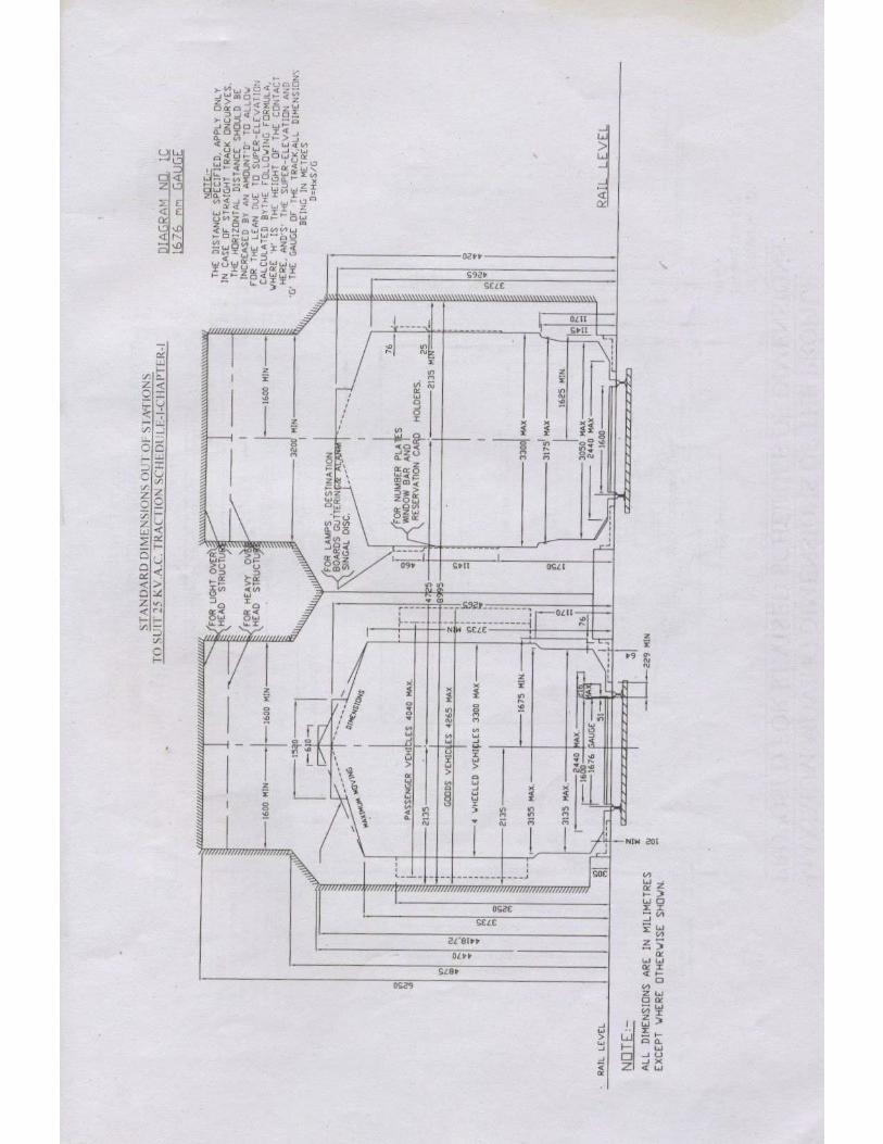

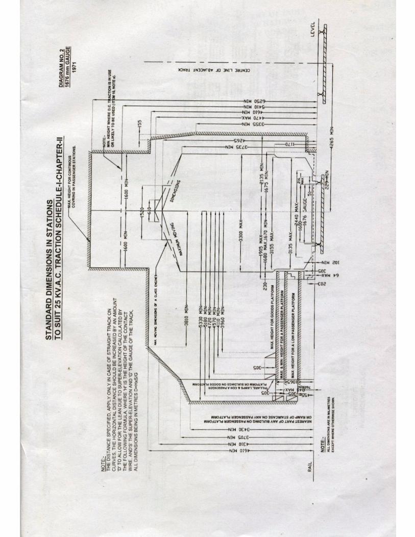

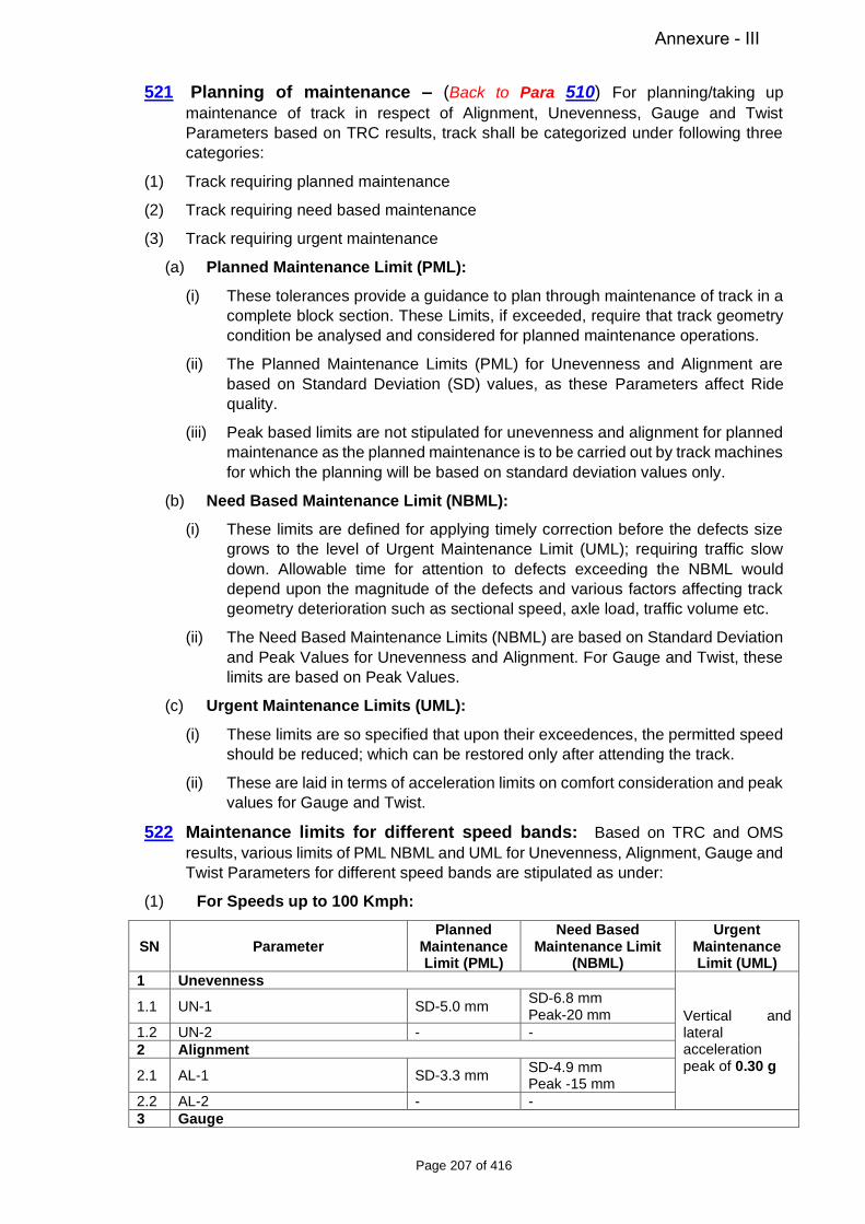
Page 207 of 416
521 Planning of maintenance – (Back to Para 510) For planning/taking up maintenance of track in respect of Alignment, Unevenness, Gauge and Twist Parameters based on TRC results, track shall be categorized under following three categories:
(1) Track requiring planned maintenance
(2) Track requiring need based maintenance
(3) Track requiring urgent maintenance
(a) Planned Maintenance Limit (PML):
(i) These tolerances provide a guidance to plan through maintenance of track in a complete block section. These Limits, if exceeded, require that track geometry condition be analysed and considered for planned maintenance operations.
(ii) The Planned Maintenance Limits (PML) for Unevenness and Alignment are based on Standard Deviation (SD) values, as these Parameters affect Ride quality.
(iii) Peak based limits are not stipulated for unevenness and alignment for planned maintenance as the planned maintenance is to be carried out by track machines for which the planning will be based on standard deviation values only.
(b) Need Based Maintenance Limit (NBML):
(i) These limits are defined for applying timely correction before the defects size grows to the level of Urgent Maintenance Limit (UML); requiring traffic slow down. Allowable time for attention to defects exceeding the NBML would depend upon the magnitude of the defects and various factors affecting track geometry deterioration such as sectional speed, axle load, traffic volume etc.
(ii) The Need Based Maintenance Limits (NBML) are based on Standard Deviation and Peak Values for Unevenness and Alignment. For Gauge and Twist, these limits are based on Peak Values.
(c) Urgent Maintenance Limits (UML):
(i) These limits are so specified that upon their exceedences, the permitted speed should be reduced; which can be restored only after attending the track.
(ii) These are laid in terms of acceleration limits on comfort consideration and peak values for Gauge and Twist.
522 Maintenance limits for different speed bands: Based on TRC and OMS results, various limits of PML NBML and UML for Unevenness, Alignment, Gauge and Twist Parameters for different speed bands are stipulated as under:
(1) For Speeds up to 100 Kmph:
SN Parameter Planned
Maintenance Limit (PML)
Need Based Maintenance Limit
(NBML)
Urgent Maintenance Limit (UML)
1 Unevenness
Vertical and lateral acceleration peak of 0.30 g
1.1 UN-1 SD-5.0 mm SD-6.8 mm Peak-20 mm
1.2 UN-2 - - 2 Alignment
2.1 AL-1 SD-3.3 mm SD-4.9 mm Peak -15 mm
2.2 AL-2 - - 3 Gauge
Annexure - III
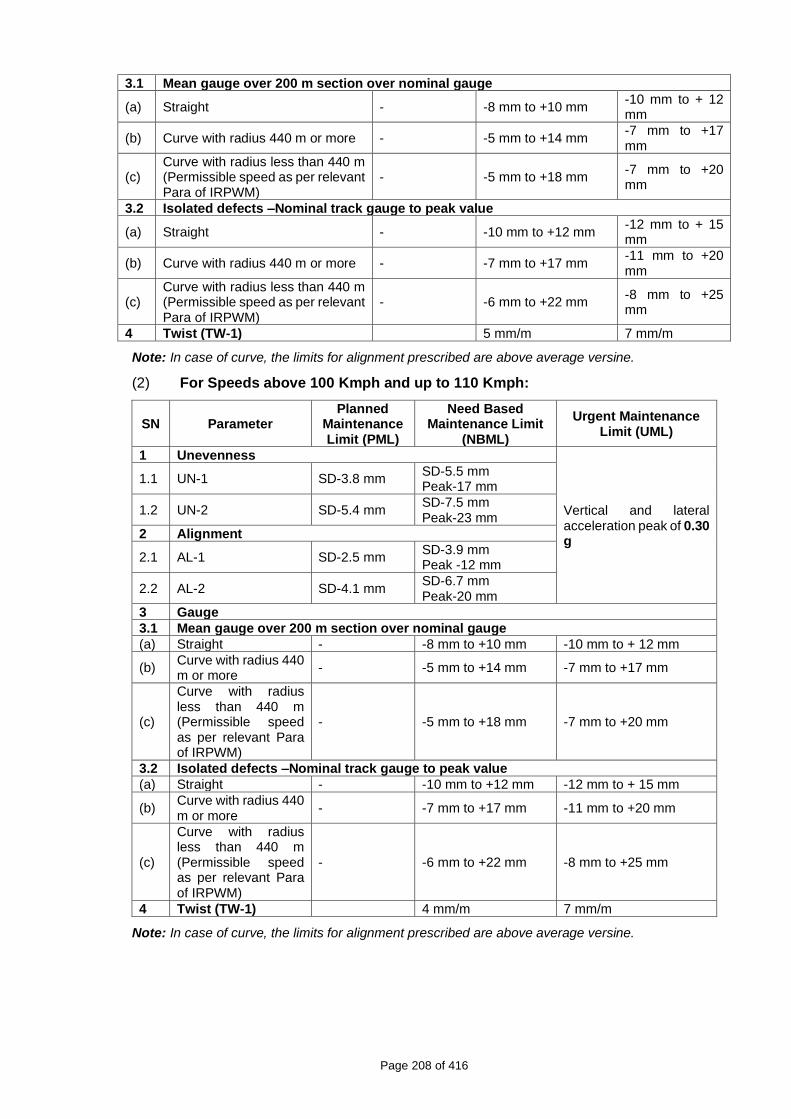
Page 208 of 416
3.1 Mean gauge over 200 m section over nominal gauge
(a) Straight - -8 mm to +10 mm -10 mm to + 12 mm
(b) Curve with radius 440 m or more - -5 mm to +14 mm -7 mm to +17 mm
(c) Curve with radius less than 440 m (Permissible speed as per relevant Para of IRPWM)
- -5 mm to +18 mm -7 mm to +20 mm
3.2 Isolated defects –Nominal track gauge to peak value
(a) Straight - -10 mm to +12 mm -12 mm to + 15 mm
(b) Curve with radius 440 m or more - -7 mm to +17 mm -11 mm to +20 mm
(c) Curve with radius less than 440 m (Permissible speed as per relevant Para of IRPWM)
- -6 mm to +22 mm -8 mm to +25 mm
4 Twist (TW-1) 5 mm/m 7 mm/m
Note: In case of curve, the limits for alignment prescribed are above average versine.
(2) For Speeds above 100 Kmph and up to 110 Kmph:
SN Parameter Planned
Maintenance Limit (PML)
Need Based Maintenance Limit
(NBML)
Urgent Maintenance Limit (UML)
1 Unevenness
Vertical and lateral acceleration peak of 0.30 g
1.1 UN-1 SD-3.8 mm SD-5.5 mm Peak-17 mm
1.2 UN-2 SD-5.4 mm SD-7.5 mm Peak-23 mm
2 Alignment
2.1 AL-1 SD-2.5 mm SD-3.9 mm Peak -12 mm
2.2 AL-2 SD-4.1 mm SD-6.7 mm Peak-20 mm
3 Gauge
3.1 Mean gauge over 200 m section over nominal gauge
(a) Straight - -8 mm to +10 mm -10 mm to + 12 mm
(b) Curve with radius 440 m or more - -5 mm to +14 mm -7 mm to +17 mm
(c)
Curve with radius less than 440 m (Permissible speed as per relevant Para of IRPWM)
- -5 mm to +18 mm -7 mm to +20 mm
3.2 Isolated defects –Nominal track gauge to peak value
(a) Straight - -10 mm to +12 mm -12 mm to + 15 mm
(b) Curve with radius 440 m or more - -7 mm to +17 mm -11 mm to +20 mm
(c)
Curve with radius less than 440 m (Permissible speed as per relevant Para of IRPWM)
- -6 mm to +22 mm -8 mm to +25 mm
4 Twist (TW-1) 4 mm/m 7 mm/m
Note: In case of curve, the limits for alignment prescribed are above average versine.

Page 209 of 416
(3) For Speeds above 110 Kmph and up to 130 Kmph:
SN Parameter Planned
Maintenance Limit (PML)
Need Based Maintenance Limit
(NBML)
Urgent Maintenance Limit
(UML)
1 Unevenness
Vertical and lateral acceleration peak of 0.25 g
1.1 UN-1 SD-3.3 mm SD-4.9 mm Peak-15 mm
1.2 UN-2 SD-5.1 mm SD-7.4 mm Peak-22 mm
2 Alignment
2.1 AL-1 SD-2.5 mm SD-3.6 mm Peak -11 mm
2.2 AL-2 SD-3.5 mm SD-5.3 mm Peak-16 mm
3 Gauge 3.1 Mean gauge over 200 m section over nominal gauge
(a) Straight - -8 mm to +10 mm -10 mm to + 12 mm
(b) Curve with radius 440 m or more - -5 mm to +14 mm -7 mm to +17 mm
(c)
Curve with radius less than 440 m (Permissible speed as per relevant Para of IRPWM)
- -5 mm to +18 mm -7 mm to +20 mm
3.2 Isolated defects –Nominal track gauge to peak value
(a) Straight - -10 mm to +12 mm -12 mm to + 15 mm
(b) Curve with radius 440 m or more - -7 mm to +17 mm -11 mm to +20 mm
(c)
Curve with radius less than 440 m (Permissible speed as per relevant Para of IRPWM)
- -6 mm to +22 mm -8 mm to +25 mm
4 Twist (TW-1) 4 mm/m 6 mm/m
Note: In case of curve, the limits for alignment prescribed are above average versine.
(4) For Speeds above 130 Kmph and up to 160 Kmph:
SN Parameter Planned
Maintenance Limit (PML)
Need Based Maintenance Limit (NBML)
Urgent Maintenance Limit (UML)
1 Unevenness Vertical and lateral acceleration peak of 0.20 g
1.1 UN-1 SD-2.9 mm SD-4.4 mm Peak-13 mm
1.2 UN-2 SD-4.4 mm SD-6.6 mm Peak-20 mm
2 Alignment
2.1 AL-1 SD-1.9 mm SD-3.6 mm Peak -11 mm
2.2 AL-2 SD-2.5 mm SD-4.9 mm Peak-15 mm
3 Gauge
3.1 Mean gauge over 200 m section over nominal gauge
(a) Straight - -6 mm to +10 mm -8 mm to + 12 mm
(b) Curve with radius 440 m or more - -5 mm to +13
mm -7 mm to +15 mm
(c) Curve with radius less than 440 m (Permissible speed as per relevant Para of IRPWM)
- -5 mm to +18 mm -7 mm to +20 mm

Page 210 of 416
3.2 Isolated defects –Nominal track gauge to peak value
(a) Straight - -8 mm to +12 mm -10 mm to + 15 mm
(b) Curve with radius 440 m or more - -6 mm to +16
mm -9 mm to +20 mm
(c) Curve with radius less than 440 m (Permissible speed as per relevant Para of IRPWM)
- -6 mm to +22 mm -8 mm to +25 mm
4 Twist (TW-1) 3.5 mm/m 5 mm/m
Note: In case of curve, the limits for alignment prescribed are above average versine.
523 Action to be taken based on TRC results: (Back to Para 510, 602, 604)
(1) Action to be taken on exceedence of UML:
Spots/blocks exceeding track Parameter limits, and acceleration peak limits set as UML should be noted by the ADEN and SSE accompanying the TRC and suitable speed restrictions have to be immediately imposed, which shall be relaxed only after suitable attention/maintenance of track at concerned location. Similar action should be taken on exceedence of UML during OMS run also.
(2) Action to be taken on exceedence of NBML:
(i) The blocks requiring Need Based Maintenance on the basis of laid down SD based NBML and isolated spots on the basis of laid down Peak based NBML shall be identified using offline software or through TMS. All such blocks and isolated spots should be attended within a reasonable time of TRC run so that good ride quality is maintained and the track geometry does not exceed the UML. The reasonable time would be different for different sections depending upon the magnitude of defects, cause of the defect, Traffic Density of the section, Maximum Permissible Speed of the section etc. The officials responsible for maintenance at various levels have to plan the deployment of maintenance resources keeping in view the relative priority and availability of maintenance resources.
(ii) Gap between two successive NBML locations in block sections/yards should also be tamped while attending these NBML locations if this gap is less than/equal to 200 m. (1 TRC block).
(iii) While attending an NBML block in the yard in which any portion of the turnout falls, the entire turnout should be tamped.
(3) Planning of through tamping based on PML:
(i) The blocks requiring planned maintenance on the basis of laid down SD based PML shall be identified for block sections and for yards separately using off line software or through TMS.
The Block Section for any main line should be treated from block (TRC Block of 200 m) of last SEJ of preceding station to block of first SEJ of current station. Both the blocks containing above SEJ would be excluded from the block section on any particular line (UP & DOWN separately).
Similarly, the Yard would be treated from a Block of 200 m containing 1st SEJ to Block of last SEJ on any particular line (UP & DOWN separately) of the concerned station/yard.
In case of CWR through yards, the yard should be taken as 50 metres beyond farthest SRJ/ Back of crossing of turnout from centre of station yard on either side on any particular line (UP and DN separately).
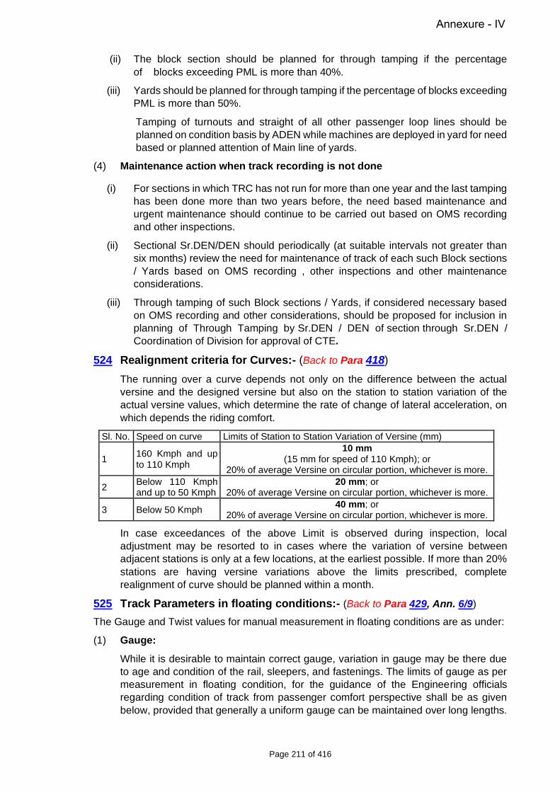
Page 211 of 416
(ii) The block section should be planned for through tamping if the percentage of blocks exceeding PML is more than 40%.
(iii) Yards should be planned for through tamping if the percentage of blocks exceeding PML is more than 50%.
Tamping of turnouts and straight of all other passenger loop lines should be planned on condition basis by ADEN while machines are deployed in yard for need based or planned attention of Main line of yards.
(4) Maintenance action when track recording is not done
(i) For sections in which TRC has not run for more than one year and the last tamping has been done more than two years before, the need based maintenance and urgent maintenance should continue to be carried out based on OMS recording and other inspections.
(ii) Sectional Sr.DEN/DEN should periodically (at suitable intervals not greater than six months) review the need for maintenance of track of each such Block sections / Yards based on OMS recording , other inspections and other maintenance considerations.
(iii) Through tamping of such Block sections / Yards, if considered necessary based on OMS recording and other considerations, should be proposed for inclusion in planning of Through Tamping by Sr.DEN / DEN of section through Sr.DEN / Coordination of Division for approval of CTE.
524 Realignment criteria for Curves:- (Back to Para 418)
The running over a curve depends not only on the difference between the actual versine and the designed versine but also on the station to station variation of the actual versine values, which determine the rate of change of lateral acceleration, on which depends the riding comfort.
Sl. No. Speed on curve Limits of Station to Station Variation of Versine (mm)
1 160 Kmph and up to 110 Kmph
10 mm (15 mm for speed of 110 Kmph); or
20% of average Versine on circular portion, whichever is more.
2 Below 110 Kmph and up to 50 Kmph
20 mm; or 20% of average Versine on circular portion, whichever is more.
3 Below 50 Kmph 40 mm; or 20% of average Versine on circular portion, whichever is more.
In case exceedances of the above Limit is observed during inspection, local adjustment may be resorted to in cases where the variation of versine between adjacent stations is only at a few locations, at the earliest possible. If more than 20% stations are having versine variations above the limits prescribed, complete realignment of curve should be planned within a month.
525 Track Parameters in floating conditions:- (Back to Para 429, Ann. 6/9)
The Gauge and Twist values for manual measurement in floating conditions are as under:
(1) Gauge:
While it is desirable to maintain correct gauge, variation in gauge may be there due to age and condition of the rail, sleepers, and fastenings. The limits of gauge as per measurement in floating condition, for the guidance of the Engineering officials regarding condition of track from passenger comfort perspective shall be as given below, provided that generally a uniform gauge can be maintained over long lengths.
Annexure - IV

Page 212 of 416
a) On straight Track -6 mm to +6 mm b) On curves with radius 440 m or more -6 mm to +15 mm c) On curves with radius less than 440 m Up to + 20 mm
In case of exceedences of these limits, the results of last TRC/OMS shall be analyzed for planning suitable maintenance action.
(2) Twist:
It is desirable to maintain the track geometry for a comfortable ride at Sectional Speed. The limits of twists as per measurement in floating condition, for guidance of the Engineering officials regarding condition of track from passenger comfort perspective shall be as under; (to be calculated on a base of 3.0 m)
(i) On straight and curve track, other than transition - 3.5 mm/m
(ii) On transition of curve- 2.1 mm/m (Local defects above Designed value)
In case of exceedences of above limits, the results of last TRC/OMS shall be analyzed for planning suitable maintenance action.
526 Track Parameters for low speeds:-
For guidance of field officials, following track Parameters are stipulated in floating conditions, for maintenance of tracks where speeds are low such as worksite, yard line, etc.
Speed (in Kmph)
Peak value of UN (on 3.6 m chord)
in mm
Peak value of twist (on 3.0 m chord)
in mm
Permissible gauge range
Up to 45 22 18 -10 to +27 mm Up to 30 24 21 -10 to +27 mm Up to 15 33 25 -12 to +27 mm
527 Stability of trains against derailment: The stability of trains against derailment depends upon several factors such as track geometry, vehicle characteristics and state of their maintenance and speed of the particular vehicle at relevant point of time etc. Rail wheel interaction is, thus, a complex phenomenon and, therefore, safety tolerance for track alone cannot be prescribed in Isolation. Accordingly, safety tolerances for maintenance of track have not been prescribed on Indian Railways. Each derailment case, therefore, needs careful examination of all available evidence, in respect of track, rolling stock, speed and other factors considered relevant, to arrive at the cause. The provisions and tolerances mentioned herein before and elsewhere in this Manual are with a view to maintain track geometry for good riding comfort considered and deviation from these maintenance Parameters should not be considered alone for cause of accident without examining all evidences mentioned above.
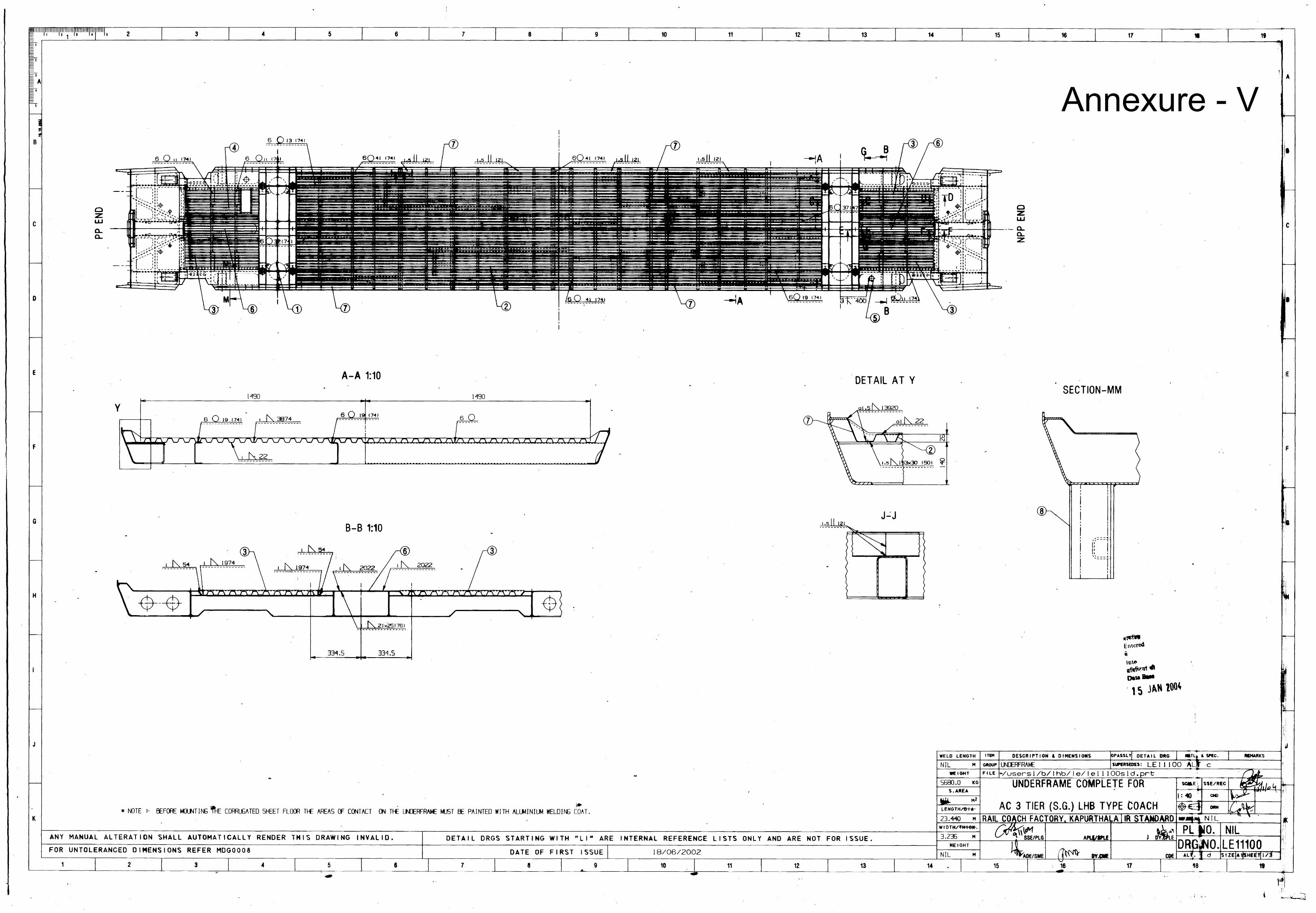
Annexure - V
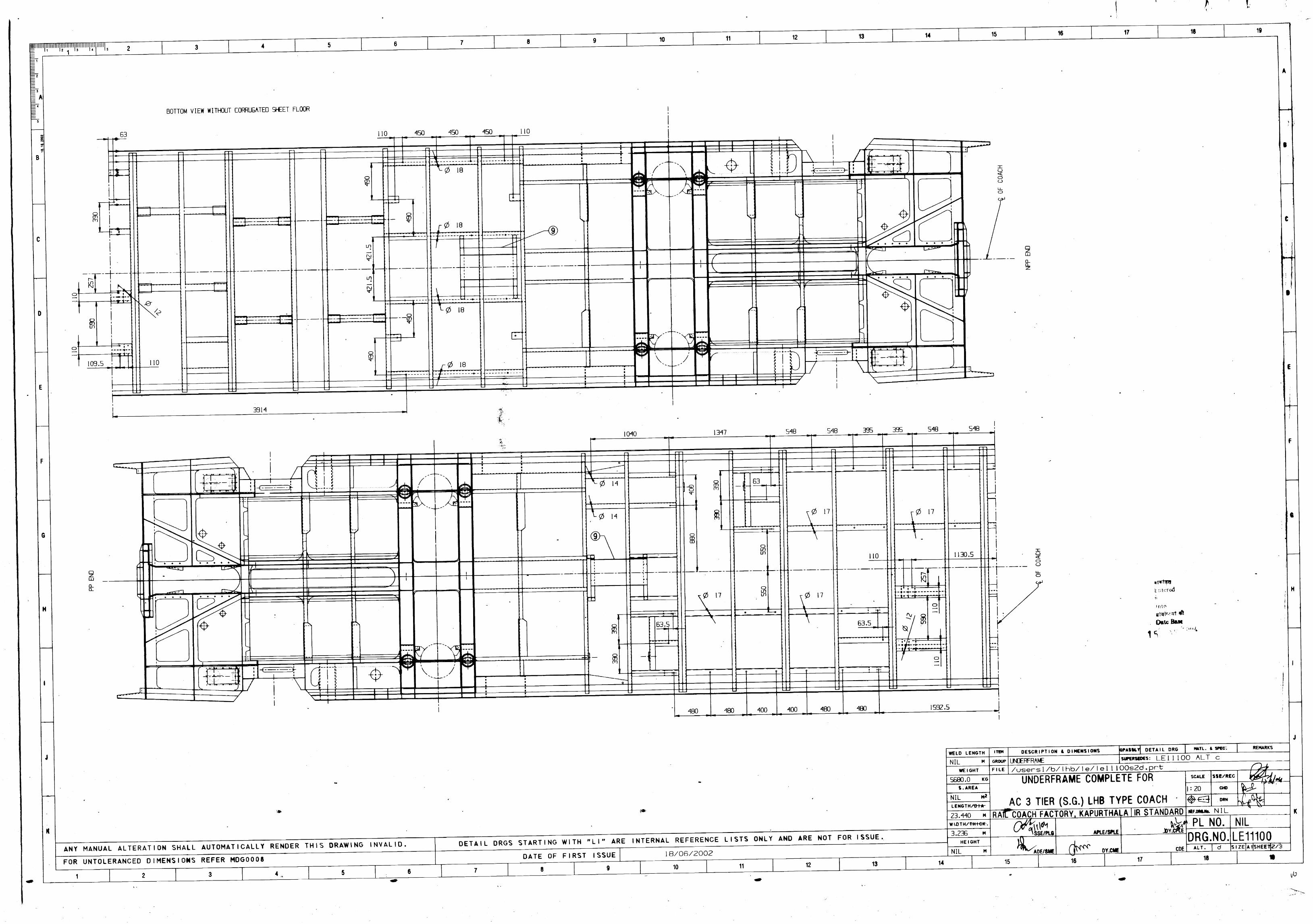
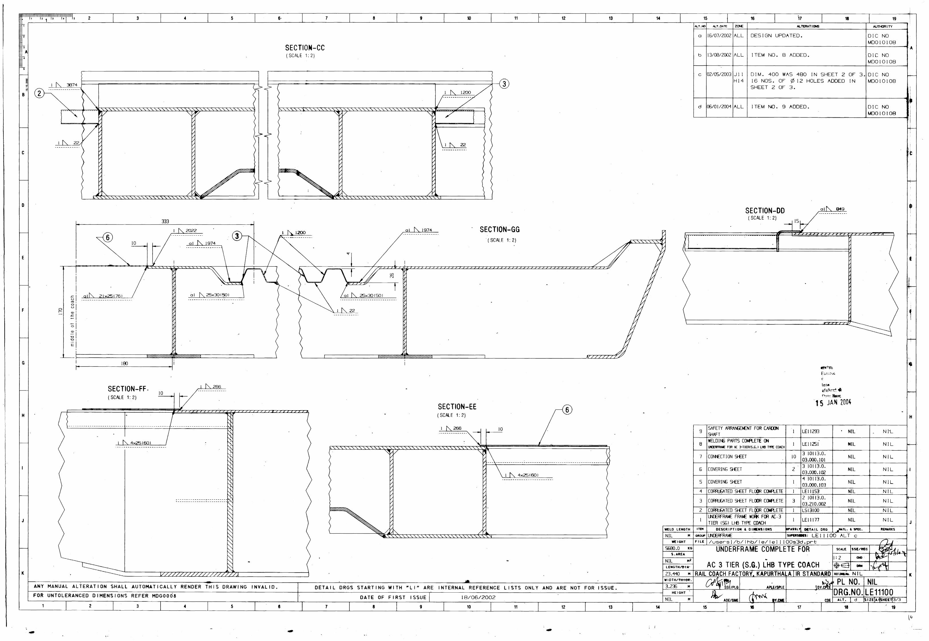

Annexure - VI

Annexure - VII