Embed Size (px)
Citation preview

DEVELOPMENT OF ROTARY CRANE SYSTEM CONTROLLER USING
FUZZY LOGIC CONTROLLER: MEMBERSHIP FUNCTION STUDY
MOHD AZRI BIN AKHIAK
A project report submitted in partial
fulfillment of the requirement for the award of the
Degree of Master of Electrical Engineering
Faculty of Electrical and Electronics Engineering
Universiti Tun Hussein Onn Malaysia
JANUARY 2012

v
ABSTRACT
The rotary crane also known as a tower crane is widely being used in the
construction of higher buildings. The crane is consists of a jib that rotates in a
horizontal plane around a fixed vertical axis and a trolley that holds the load which
can move linearly along the jib. This study only focuses on the linear motion of
trolley along the jib. The challenging process in order to control the crane are to
make sure the trolley stop at the desired position and to deal with swing phenomenon
introduced by the trolley motion. But, for the beginning of this study, the position
control issue needs to be considered. Since many controllers can be implemented in
this system in order to control the position, thus the implementation of practical
controller must be investigated. A practical controller known as a fuzzy logic
controller with various types of membership functions is implemented to control the
position of the trolley. Since fuzzy logic controller is known as non-model based
controller, hence it will be less time consuming to design. The scope of this study is
limited only for four types of membership function which are common triangular,
gaussian, trapezoidal and generalized bell membership function due to their
similarities of symmetry characteristics. The performance of fuzzy logic controller
with those membership functions is recorded and compared by using Simulink
(MATLAB) simulation.

vi
ABSTRAK
Kren berputar atau juga dikenali sebagai kren menara digunakan secara meluas
dalam sektor pembinaan bangunan-bangunan tinggi. Kren ini terdiri daripada lengan
yang boleh berputar pada satah melintang dimana ia mengelilingi paksi tegak dan
mempunyai troli yang berupaya untuk mengangkat beban dan bergerak secara linear
di sepanjang lengan. Namun, kajian ini hanya memfokuskan kepada pergerakan
linear troli sepanjang lengan kren tersebut. Proses yang mencabar dalam mengawal
kren adalah untuk memastikan troli ini berhenti tepat pada posisi yang dikehendaki
dan menangani fenomena ayunan yang dicetuskan oleh pergerakan troli. Sebagai
permulaan, isu berkaitan kawalan posisi akan diambilkira terlebih dahulu. Oleh
kerana pelbagai pengatur boleh diaplikasikan ke atas sistem ini untuk mengawal
posisi, maka perlaksanaan pengatur yang praktikal perlu di siasat. Salah satu
pengatur yang praktikal dipanggil pengatur logik kabur dengan fungsi kesertaan yang
pelbagai digunakan untuk mengawal posisi troli. Oleh kerana pengatur logik kabur
ini juga dikenali dengan pengatur yang tidak bersandarkan kepada model, maka ia
menjimatkan masa untuk direkabentuk. Skop kajian ini hanya terhad kepada empat
fungsi kesertaan iaitu triangular, gaussian, trapezoidal dan generalized bell
disebabkan persamaan ciri simetri mereka. Prestasi pengatur logik kabur bersama
fungsi-fungsi kesertaan itu akan direkod dan dibandingkan menggunakan simulasi
perisian Simulink (MATLAB).

vii
TABLE OF CONTENTS
TITLE i
DECLARATION ii
DEDICATION iii
ACKNOWLEDGEMENT iv
ABSTRACT v
TABLE OF CONTENTS vii
LIST OF TABLES ix
LIST OF FIGURES x
LIST OF SYMBOLS AND ABBREVIATIONS xii
LIST OF APPENDICES xiv
CHAPTER 1 INTRODUCTION 1
1.1 Project overview 1
1.2 Problem statement 2
1.3 Project objective 3
1.4 Project scope 3
1.5 Project report layout 4
CHAPTER 2 LITERATURE REVIEW 5
2.1 Related work 5
2.2 Types of crane 6
2.2.1 Gantry crane 7
2.2.2. Rotary crane 8
2.2.3 Boom crane 9
2.3 Fuzzy logic controller system 10

viii
2.3.1 Fuzzification 11
2.3.2 Rule base 14
2.3.3 Inference engine 15
2.3.4 Defuzzification 16
CHAPTER 3 METHODOLOGY 18
3.1 Introduction 18
3.2 Proposed plant 18
3.2.1 Rotary crane system structure 18
3.2.2 DC motor position modeling 20
3.3 Proposed controller 24
3.4 Fuzzy logic controller design 24
3.4.1 Fuzzification interface 25
3.4.2 Fuzzy inference mechanism 30
3.4.3 Fuzzy rules 30
3.4.4 Defuzzification interface 33
CHAPTER 4 RESULT AND ANALYSIS 34
4.1 Introduction 34
4.2 System performance without controller 35
4.3 System performance of PID controller and
fuzzy logic controller 36
4.4 System performance of fuzzy logic controller
with different types of membership function 40
CHAPTER 5 CONCLUSION AND RECOMMENDATION 45
5.1 Conclusion 45
5.2 Recommendation 46
REFERENCES 47
APPENDICES 49

ix
LIST OF TABLES
2.1 Example of rule base for air conditioner system 15
3.1 Parameter of jib’s DC motor (Faulhaber DC motor) 22
3.2 Fuzzy rules for position control 31
4.1 Performance comparison between PID controller
and fuzzy logic controller 40
4.2 Performance comparison between different types of
fuzzy logic controller 43

x
LIST OF FIGURES
2.1 Gantry crane 7
2.2 Rotary crane 8
2.3 Boom crane 9
2.4 Structure of fuzzy logic controller system 10
2.5 Triangular membership function shape 12
2.6 Gaussian membership function shape 12
2.7 Trapezoidal membership function shape 13
2.8 Generalized bell membership function shape 13
2.9 Sigmoidal membership function shape 14
3.1 Main components of rotary crane system (1: base plate,
2: tower, 4: jib, 6: trolley, 7: steel cable, 8: payload) 19
3.2 Components of jib (2: tower, 4: jib, 5: jib DC motor,
9: jib optical encoder) 19
3.3 Underside of jib (4: jib, 13: linear guide, 23: trolley pulley,
24: belt) 20
3.4 Circuit diagram of DC motor 20
3.5 Block diagram of proposed controller 24
3.6 Triangular membership function for (a) error and (b) delta of
error input variables 26
3.7 Gaussian membership function for (a) error and (b) delta of
error input variables 27
3.8 Trapezoidal membership function for (a) error and (b) delta
of error input variables 28
3.9 Generalized bell membership function for (a) error and
(b) delta of error input variables 29

xi
3.10 Triangular membership function for voltage output
variable 30
3.11 Illustration of how fuzzy rules can cover all possible
positions 33
4.1 Rotary crane system without controller in Simulink 35
4.2 Response of trolley position without controller 36
4.3 Rotary crane system with PID controller in Simulink 37
4.4 Rotary crane system with fuzzy logic controller in Simulink 37
4.5 Response of trolley position at input reference 10 cm with
PID controller and fuzzy logic controller 38
4.6 Response of trolley position at input reference 20 cm with
PID controller and fuzzy logic controller 38
4.7 Response of trolley position at input reference 30 cm with
PID controller and fuzzy logic controller 39
4.8 Response of trolley position at input reference 40 cm with
PID controller and fuzzy logic controller 39
4.9 Response of trolley position at input reference 10 cm with
different types of membership function 41
4.10 Response of trolley position at input reference 20 cm with
different types of membership function 42
4.11 Response of trolley position at input reference 30 cm with
different types of membership function 42
4.12 Response of trolley position at input reference 40 cm with
different types of membership function 43

xii
LIST OF SYMBOLS AND ABBREVIATIONS
µe
µ
- degree of membership function of error
Δe
µ
- degree of membership function of delta of error
u
µ
- degree of membership function of voltage ouput
o
∨ - maximum operator
- output of COG
˄ - minimum operator
Ia
V
- armature current
a
J
- rated voltage DC motor
m
T
- equivalent of moment inertia
m
B
- motor torque
m
e
- damping ratio
b
θ
- motor back emf
m
ω
- position in terms of angle
m
r
- angular velocity
pulley
K - motor torque constant factor
- radius of trolley pulley from pivot to end of tooth
R - motor terminal resistance
L - motor terminal inductance resistance
θref
θ
- reference position in terms of angle
act
BOA - Bisector of Area
- actual position in terms of angle
COG - Centroid of Gravity
DOF - Degree of Freedom
DC - Direct Current
FLC - Fuzzy Logic Controller

xiii
gaussmf - Gaussian Membership Function
gbellmf - Generalized Bell Membership Function
GUI - Graphic User Interface
LQR - Linear Quadratic Regulator
MF - Membership Function
MOM - Mean of Maximum
NB - Negative Big
NS - Negative Small
PB - Positive Big
PID - Proportional Integral Derrivative
PS - Positive Small
trapmf - Trapezoidal Membership Function
trimf - Triangular Membership Function
sigmf - Sigmoidal Membership Function
Z - Zero

xiv
LIST OF APPENDICES
APPENDIX TITLE PAGE
A S-Function Source Code for Triangular
Membership Function 49
B S-Function Source Code for Gaussian
Membership Function 55
C S-Function Source Code for Trapezoidal
Membership Function 60
D S-Function Source Code for Generalized Bell
Membership Function 69

CHAPTER 1
INTRODUCTION
1.1 Project overview
A crane is one of major equipment or machine in industries, exists in most places;
from domestic industries to naval yards to warehouses. It uses levers and/or pulleys
for gripping, lifting and moving loads horizontally, as well as lowering and release
the gripper back. The basic task of crane is to move payload (usually heavy load)
from one point to another point. There are many types of crane that have been used
for this purpose, such as rotary crane, gantry crane, boom crane and others.
Until now, crane was manually operated by skillful and professional person.
Safety is the most important thing to consider in handling the crane. So, the crane
must be operated in safe operating manner and procedures. Although the guidelines
have been sketched to avoid any unwanted incident, still there are some chances for
the accident can occur in future due to the operator is a human being. Perhaps, the
solution is to substitute the automatic crane system with the best controller strategies
as a replacement for the manual-controlled crane system.

2
1.2 Problem statement
Nowadays, cranes become larger and higher. Due to that, the transportation payload
along the trolley system to the desired position needs faster time. Since the payload
move in high speed, it will result the payload swing extremely when it suddenly stop
after reach the final position. This excessive swing is not only reduces the efficiency
of the cranes, even can cause hazard and safety problem in the complicated working
environment.
Moreover, skilful operator still needed to control gantry crane manually based
on his experiences to reduce and stop the swing immediately at the right position.
The failure of controlling crane can cause accident and may harm people
surrounding. Therefore, many researchers have given a lot of efforts in developing a
control algorithms and designing controllers that can be used and realized in nature.
Since to that, many control strategies based on the classic or modern control
techniques have been proposed, investigated and tested in the laboratory level for the
control of crane such as PID adaptive control and optimal control nonlinear control.
All the design control strategies have the same objective that should take into
account which is to minimize the consume time to move the payload from initial
position to the final position and reduce the swing of payload during transportation
process. Besides, there are several issues to deal in order to design new control
strategy. The important ones is the simplification of algorithm structure which make
the controller is easy to design and adjust without neglecting the performance of the
controller. Therefore, the implementation of practical controller that will deal to the
issue must be investigated.

3
1.3 Project objective
The objectives of this project are;
i) To control the position of trolley by using model-based PID controller and
non model-based fuzzy logic controller with different types of membership
function via simulation
iii) To compare the performance of position control between PID controller and
fuzzy logic controller
iv) To compare the performance of position control between different types of
membership function of fuzzy logic controller
1.4 Project scope
The rotary crane system used for this study involving lab scaled; 3-DOF Crane
System (manufactured by Quanser). This lab scale rotary crane system consists of 3
subsystems namely payload, jib and tower. But, this study focuses only on the jib
part.
The scope of proposed fuzzy logic controller is limited to four membership
functions which are triangular, gaussian, trapezoidal and generalized bell as a
proposed controller for position control.

4
1.5 Project report layout
This project report is organized as follows;
i) Chapter 1 briefs the overall background of the study. A quick glimpse of
study touched in first sub-topic. The heart of study such as problem
statement, project objective, project scope and project report layout is present
well through this chapter.
ii) Chapter 2 covers the literature review of previous case study based on fuzzy
logic controller background and development. Besides, general information
about crane and theoretical revision on fuzzy logic control system also
described in this chapter.
iii) Chapter 3 presents the methodology used to design fuzzy logic controller and
applied to the rotary crane system. All the components that have been used in
designing of fuzzy logic controller are described well in this chapter.
iv) Chapter 4 reports and discuss on the results obtained based on the problem
statements as mentioned in the first chapter. The simulation results from PID
controller and the new proposed of fuzzy logic controller with different
membership function will be analyzed with helps from set of figures and
tables.
v) Chapter 5 will go through about the conclusion and recommendation for
future study. References cited and supporting appendices are given at the end
of this project report while the documentation CD also available and attached
on the back cover of this project report for future reference.

CHAPTER 2
LITERATURE REVIEW
2.1 Related work
Since fuzzy logic controller can mimic human behaviour, many researchers applied
fuzzy logic controller to control either overhead crane, gantry crane as well as rotary
crane. A thorough literature overview was done on the usage of fuzzy logic
controller as applied to the various crane systems.
Lee, H. H. and Cho, S. K. (2001) proposed a new fuzzy logic anti swing
control for industrial three dimensional overhead cranes. However, PID controller
still approached for position control which is based on model controller.
Omar, H.M (2003) proposed a controller with robust and fast for gantry and
rotary cranes. The result shows that the fuzzy logic controller has smaller transfer
time and overshoots unfortunately, with higher swing angles. Besides, the fuzzy
logic controller uses mapping method which needs delayed feedback controller
before fuzzy logic can be designed thus resulting time consuming.
Wahyudi & Jalani, J. (2005) designed and implemented robust Fuzzy Logic
Controller for An Intelligent Gantry Crane System. The experimental results for anti
swing control successfully proved that fuzzy logic controller is better compared to
the conventional PID controller. However, the application of the fuzzy logic

6
controller that has been proposed is for gantry crane which is their parameter is
totally different with rotary crane.
Othman, M. Z. (2006) proposed a rough controller as a replacement for fuzzy
logic controller which is based on mathematical computation to control the overhead
travelling crane. The result shows that, it is just satisfactory, even more the quality
index for both controllers does not differ very much. The complex mathematical
modelling involves in designing process is not practicable.
Ruslee, R. , Jalani, J. & Abdullah, J. (2008) proposed Anti-Swing Control
Strategy for Automatic 3 D.O.F. Crane System Using Fuzzy Logic Controller. The
simpler and practical design of fuzzy logic controller applied for both position and
anti swing control. It is obvious that the performance of fuzzy logic controller is
better compared to Linear Quadratic Regulator (LQR) controller.
Based on those related work, the researchers make a great efforts to propose
the good controller in the industrial setup to overcome the crane problems. Their
applications of each method differ and still, the fuzzy logic controller is better
controller compared to other conventional controller yet. Thus, the further
investigation of this controller is needed in depth.
The approach of this study is similar to Ruslee, R. , Jalani, J. & Abdullah, J.
(2008) in designing the fuzzy logic controller but for position control only. The
investigation will be based on the different types of membership function applied on
fuzzy logic controller.
2.2 Types of crane
There are many different styles and variation of cranes that abound in the world.
Each of them is used for specific tasks but most of them are used for industrial
purposes and are considered as heavy equipment machinery. However, in general
there are three types of cranes in industries which can be classified in terms of their
mechanical structures and dynamics. They are classified as gantry, rotary, and boom
cranes.

7
2.2.1 Gantry crane
Gantry crane has a hoist in a trolley which runs horizontally along gantry rails and
usually fitted underneath a beam spanning between uprights which themselves have
wheels so that the whole crane can move at right angles to the desired direction of
the gantry rails. Gantry cranes are fixed to the ground and give offer a combination
of height and lifting capacity as shown in the Figure 2.1.
This type of crane is characterized by a trolley moving over a jib or glider.
The trolley’s movement can be described with a one-degree-of-freedom model. In
some cases, the jib is mounted on another set of orthogonal railings in what is called
bridge cranes. In this case, the trolley can move in a two-dimensional horizontal
plane. They are common in factories because of their low cost, ease of assembly, and
maintenance. They are also used in mines, steel-mill productions lines, and transport
industry.
Figure 2.1: Gantry crane

8
2.2.2 Rotary crane
The rotary crane or also known as tower crane is a modern form of balance crane. It
was fixed to the ground or jacked up and supported by the structure is being built.
The rotary crane as shown in the Figure 2.2 often gives the best combination of
height and lifting. Rotary crane is a common fixture at any major construction site. It
is pretty hard to miss and often rise hundreds of feet into the air and can reach out
just as far.
The crane was consists of a jib that rotates in a horizontal plane around a
fixed vertical axis. The hoist motor and transmissions are located on the mechanical
deck on the counter-jib while the trolley motor is located on the jib. The trolley that
holds the load can move radically over the jib. Hence, the combined motion of the
trolley and jib can place the load at any point in the horizontal plane within the reach
of the crane. The load is attached to the trolley using a set of cables.
Figure 2.2: Rotary crane

9
2.2.3 Boom crane
Shown in the Figure 2.3 was a boom crane type which is very common on ships and
in harbors. The typical boom crane was a pivoting structure equipped with double
tread wheels. These cranes were placed docksides for the loading and unloading of
cargo where they replaced or complemented older lifting method.
In general, a boom crane consists of a rotating base to which a boom is
attached. The load hangs from the tip of the boom by a set of cables and pulleys. The
rotational movement of the base along with the luff movement of the boom places tip
over any point in the horizontal plane that is in reach of the crane. Meanwhile,
changing the elevation (luff) angle of the boom causes a change in the radial and
vertical positions of the load. The structure of boom cranes supports loads in
compression, whereas rotary and gantry cranes support loads in a bending fashion.
This makes boom cranes more compact than rotary and gantry cranes of similar
capacities. Boom cranes are mounted on ships to transfer cargo between ships or on
harbor pavements to transfer cargo between ships and offshore structures.
Figure 2.3: Boom crane

10
2.3 Fuzzy logic controller system
Fuzzy logic and fuzzy control theories added a new dimension to control systems
engineering in the early 1970s. From its beginnings as mostly heuristic, somewhat
ad-hoc, more recent and rigorous approaches to fuzzy control theory have helped
make it integral part of modem control theory and produced many exciting results.
Fuzzy logic is a technique to embody human like thinking which is much less
rigid than the calculations computer generally perform into a control system. Fuzzy
controller can be designed to emulate human deductive thinking, that is, the process
people use to infer conclusion from what they know. Meanwhile, conventional
controller requires formal modeling of the physical reality of any plant. Apart from
that, fuzzy control incorporates ambiguous human logic into computer programs. It
suit control problem that can’t be easily represented by mathematical model. Design
of such controller leads to faster development and implementation cycles due to its
unconventional approach.
There are four important elements in the fuzzy logic controller system
structure which are fuzzifier, rule base, inference engine and defuzzifier. Details of
the fuzzy logic controller system structure can be seen in Figure 2.4 below. Firstly, a
crisp set of input data are gathered and converted to a fuzzy set using fuzzy linguistic
variables, fuzzy linguistic terms and membership functions. This step also known as
fuzzification. Afterwards, an inference is made base on a set of rules. Lastlty, the
resulting fuzzy output is mapped to a crisp output using the membership functions, in
the defuzzification step.
Figure 2.4: Structure of fuzzy logic controller system
Fuzzification
Inference Engine
Rule Base Defuzzification
Crisp input data Crisp output data
fuzzy input data fuzzy output data

11
2.3.1 Fuzzification
Fuzzification is a process of making a crisp quantity fuzzy. Before this process is
taken in action, the definition of the linguistic variables and terms is needed.
Linguistic variables are the input or output variables of the system whose values are
words or sentences from a natural language, instead of numerical values. A linguistic
variable is generally decomposed into asset of linguistic terms. Example, in the air
conditioner system, Temperature,T is linguistic variable represents the temperature
of a room. To qualify the temperature, terms such as “hot” and “cold” are used in
real life. Then, Temperature (T) = too cold, cold, warm, hot, too hot can be the set
of decomposition for the linguistic variable temperature. Each member of this
decomposition is called a linguistic term and can cover a portion of the overall values
of the temperature.
Next, to map the non-fuzzy input or crisp input data to fuzzy linguistic terms,
membership functions is used. In other words, a membership function is used to
quantify a linguistic term. Note that, an important characteristic of fuzzy logic is that
a numerical valu does not have to be fuzzified using only one membership function
meaning, a value can belong to multiple sets at the same time. Membership function
can be measured in percentage from 0% to 100% or as a number 0 to 1. Sometimes
membership function is also called as confidence factor. There are different forms or
shapes of membership functions such as triangular, gaussian, trapezoidal, generalized
bell and sigmoidal. The most common type of membership function used by many
applications is triangular. The type of the membership function can be context
dependent and it is generally chosen arbitrarily according to the user experience.
Figure 2.5 to Figure 2.9 shows the different types of membership function shape.

12
Figure 2.5: Triangular membership function shape
Equation for triangular membership function can be defined as follow;
≤
≤≤−−
≤≤−−
≤
=
xc
cxbbcxc
bxaabax
ax
cbaxtrimf
0
0
),,;( (2.1)
Figure 2.6: Gaussian membership function shape
Equation for gaussian membership function can be defined as follow;
2
2
2)(
),;( σσ ⋅−−
=cx
ecxgaussmf (2.2)

13
Figure 2.7: Trapezoidal membership function shape
Equation for trapezoidal membership function can be defined as follow;
≤
≤≤−−
≤≤
≤≤−−
≤
=
xd
dxccdxd
cxb
bxaabax
ax
cbaxtrapmf
0
1
0
),,;( (2.3)
Figure 2.8: Generalized bell membership function shape

14
Equation for generalized bell membership function can be defined as follow;
b
acx
cbaxgbellmf 2
1
1),,;(−
+
= (2.4)
Figure 2.9: Sigmoidal membership function shape
Equation for sigmoidal membership function can be defined as follow;
( )cxaecaxsigmf −−+=
11),;( (2.5)
2.3.2 Rule base
In a fuzzy logic control system, a rule base is constructed to control the output
variable. A fuzzy rule is a simple IF-THEN rule with a condition and conclusion. It
can be represented by the matrix table. Let say, the air conditioner system with two
input linguistic variables of temperature and humidity and one output linguistic
variable of motor speed as shown in Table 2.1.

15
Table 2.1: Example of rule base for air conditioner system
Motor speed Humidity
low moderate high
Temperature
cold medium slow slow
warm fast medium slow
hot fast fast medium
Row captions in the matrix contain the values that current room temperature can take
while column caption contain the values for humidity in the room. Each cell is the
resulting command when the input variables take the values in that row and column.
Based on the table 2.1, the maximum numbers of rules are nine (9). For instance, the
cell (3,3) can be read as follows: IF temperature is hot and humidity is high THEN
motor speed is medium.
2.3.3 Inference engine
In general, inference is a process of obtaining new knowledge through existing
knowledge. In the context of fuzzy logic control system, it can be defined as a
process to obtain the final result of combination of the result of each rule in fuzzy
value. There are many methods to perform fuzzy inference method and the most
common two of them are Mamdani and Takagi-Sugeno-Kang method.
Mamdani method was proposed by Ebrahim Mamdani as an attempt to
control a steam engine and boiler in 1975. It is based on Lofti Zadeh’s 1973 paper on
fuzzy algorithms for complex system and decision processes. This method uses the
minimum operation Rc
as a fuzzy implication and the max-min operator for the
composition. Suppose a rule base is given in the following form;
IF input x = A AND input y = B
THEN output z = C
After the aggregation process, there is a fuzzy set for each output variable that needs
defuzzification. It is possible and in many cases much more efficient, to use a single
16
spike as the output membership functions rather than a distributed fuzzy set. This is
sometimes known as a singleton output membership function. It enhances the
efficiency of defuzzification process because it greatly simplifies the computation
required by the more general Mamdani method, which finds the centroid of two
dimensional function.
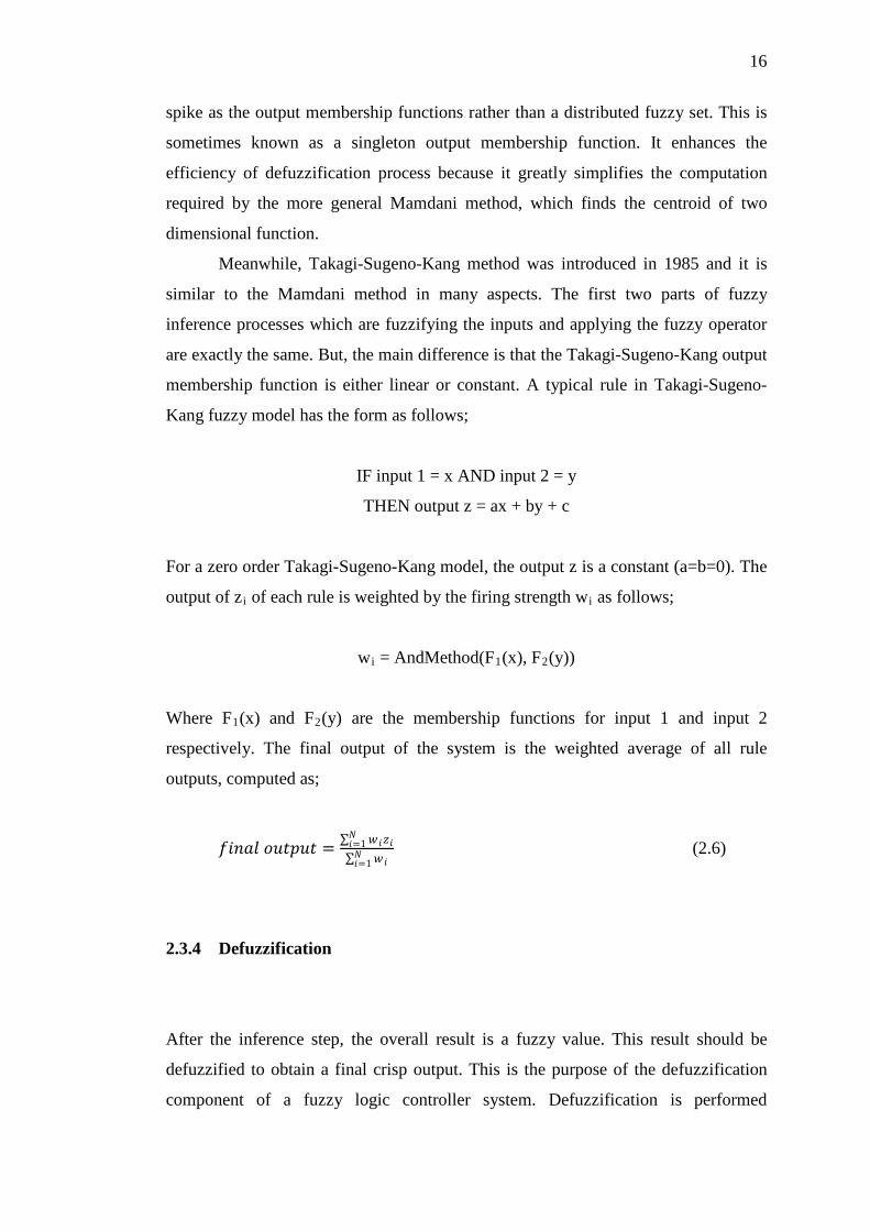
Meanwhile, Takagi-Sugeno-Kang method was introduced in 1985 and it is
similar to the Mamdani method in many aspects. The first two parts of fuzzy
inference processes which are fuzzifying the inputs and applying the fuzzy operator
are exactly the same. But, the main difference is that the Takagi-Sugeno-Kang output
membership function is either linear or constant. A typical rule in Takagi-Sugeno-
Kang fuzzy model has the form as follows;
IF input 1 = x AND input 2 = y
THEN output z = ax + by + c
For a zero order Takagi-Sugeno-Kang model, the output z is a constant (a=b=0). The
output of zi of each rule is weighted by the firing strength wi
as follows;
wi = AndMethod(F1(x), F2
(y))
Where F1(x) and F2
(y) are the membership functions for input 1 and input 2
respectively. The final output of the system is the weighted average of all rule
outputs, computed as;
𝑓𝑓𝑓𝑓𝑓𝑓𝑓𝑓𝑓𝑓 𝑜𝑜𝑜𝑜𝑜𝑜𝑜𝑜𝑜𝑜𝑜𝑜 = ∑ 𝑤𝑤𝑓𝑓𝑧𝑧𝑓𝑓𝑁𝑁𝑓𝑓=1∑ 𝑤𝑤𝑓𝑓𝑁𝑁𝑓𝑓=1
(2.6)
2.3.4 Defuzzification
After the inference step, the overall result is a fuzzy value. This result should be
defuzzified to obtain a final crisp output. This is the purpose of the defuzzification
component of a fuzzy logic controller system. Defuzzification is performed

17
according to the membership function of the output variable. There are many
different methods for defuzzification such as Centroid of Gravity (COG), Mean of
Maximum (MOM), Weighted Average, Bisector of Area (BOA), First of Maxima
and Last of Maxima. There is no systematic procedure for choosing a good
defuzzification strategy, but the selection of defuzzification procedure is depends on
the properties of the application.
Centroid of Gravity (COG) is the most frequent used and the most prevalent
and physically appealing of all defuzzification methods. The basic equation of
Centroid of Gravity (COG) as below;
𝑜𝑜𝑜𝑜 = ∫ µ𝑜𝑜 (𝑜𝑜)𝑜𝑜 𝑜𝑜𝑢𝑢𝑜𝑜
∫ µ𝑜𝑜 (𝑜𝑜)𝑜𝑜 𝑢𝑢𝑜𝑜 (2.7)
where 𝑜𝑜𝑜𝑜 is control output obtained by using Centroid of Gravity (COG)
defuzzification method.

CHAPTER 3
METHODOLOGY
3.1 Introduction
This chapter will discuss details about designing fuzzy logic controller for rotary
crane system controller.
3.2 Proposed plant
The proposed plant including lab scaled rotary crane system also known as 3-DOF
Crane System manufactured by Quanser and modeling of DC motor position.
3.2.1 Rotary crane system structure
Basically, the rotary crane system consists of the base plate, tower, jib, trolley, steel
cable and payload. The jib of rotary crane system as shown in Figure 3.1 and Figure
3.2 has a motorized gearbox (DC Motor) to move the trolley and equipped with an

19
optical encoder to measure the trolley position. The trolley need to be at the centered
position as initial condition. The maximum movement can be made by the trolley
was ±40cm or 0.4m. Even the desired position are setup, there still need to take a
safety action. At the end both side of the jib has a limit switch as a safety for trolley
movement.
Figure 3.1: Main components of rotary crane system (1: base plate, 2: tower, 4: jib, 6:
trolley, 7: steel cable, 8: payload)
Figure 3.2: Components of jib (2: tower, 4: jib, 5: jib DC motor, 9: jib optical
encoder)

20
The motor shaft of the trolley connected to a 16-tooth pulley, shown in Figure
3.3 that is interlocked with a belt. The trolley is anchored along the underside of the
jib to a linear guide and is fastened to the belt such that the motor can be used to
position the trolley along the track.
Figure 3.3: Underside of jib (4: jib, 13: linear guide, 23: trolley pulley, 24: belt)
3.2.2 DC motor position modeling
To perform the simulation of the rotary crane system, an appropriate model needs to
be established. By neglecting the dynamic model of trolley motion, the plant can be
represented by the DC motor circuit diagram as shown in Figure 3.4.
Va(t) eb(t)
Tm(t)
Jm Bm
Load
θm(t) ωm(t)
Motor
Ia(t) R L
Figure 3.4: Circuit diagram of DC motor
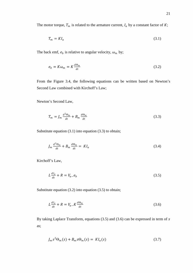
21
The motor torque, 𝑇𝑇𝑚𝑚 is related to the armature current, 𝐼𝐼𝑎𝑎 by a constant factor of 𝐾𝐾;
𝑇𝑇𝑚𝑚 = 𝐾𝐾𝐼𝐼𝑎𝑎 (3.1)
The back emf, 𝑒𝑒𝑏𝑏 is relative to angular velocity, 𝜔𝜔𝑚𝑚 by;
𝑒𝑒𝑏𝑏 = 𝐾𝐾𝜔𝜔𝑚𝑚 = 𝐾𝐾 𝑑𝑑Ѳ𝑚𝑚𝑑𝑑𝑑𝑑
(3.2)
From the Figure 3.4, the following equations can be written based on Newton’s
Second Law combined with Kirchoff’s Law;
Newton’s Second Law,
𝑇𝑇𝑚𝑚 = 𝐽𝐽𝑚𝑚𝑑𝑑2Ѳ𝑚𝑚𝑑𝑑𝑑𝑑
+ 𝐵𝐵𝑚𝑚𝑑𝑑Ѳ𝑚𝑚𝑑𝑑𝑑𝑑
(3.3)
Substitute equation (3.1) into equation (3.3) to obtain;
𝐽𝐽𝑚𝑚𝑑𝑑2Ѳ𝑚𝑚𝑑𝑑𝑑𝑑
+ 𝐵𝐵𝑚𝑚𝑑𝑑Ѳ𝑚𝑚𝑑𝑑𝑑𝑑
= 𝐾𝐾𝐼𝐼𝑎𝑎 (3.4)
Kirchoff’s Law,
𝐿𝐿 𝑑𝑑𝐼𝐼𝑎𝑎𝑑𝑑𝑑𝑑
+ 𝑅𝑅 = 𝑉𝑉𝑎𝑎−𝑒𝑒𝑏𝑏 (3.5)
Substitute equation (3.2) into equation (3.5) to obtain;
𝐿𝐿 𝑑𝑑𝐼𝐼𝑎𝑎𝑑𝑑𝑑𝑑
+ 𝑅𝑅 = 𝑉𝑉𝑎𝑎−𝐾𝐾𝑑𝑑Ѳ𝑚𝑚𝑑𝑑𝑑𝑑
(3.6)
By taking Laplace Transform, equations (3.5) and (3.6) can be expressed in term of 𝑠𝑠
as;
𝐽𝐽𝑚𝑚𝑠𝑠2Ѳ𝑚𝑚 (𝑠𝑠) + 𝐵𝐵𝑚𝑚𝑠𝑠Ѳ𝑚𝑚 (𝑠𝑠) = 𝐾𝐾𝐼𝐼𝑎𝑎(𝑠𝑠) (3.7)

22
𝐿𝐿𝑠𝑠𝐼𝐼𝑎𝑎(𝑠𝑠) + 𝑅𝑅𝐼𝐼𝑎𝑎(𝑠𝑠) = 𝑉𝑉𝑎𝑎(𝑠𝑠) − 𝐾𝐾𝑠𝑠Ѳ𝑚𝑚 (𝑠𝑠) (3.8)
From equation (3.7), 𝐼𝐼𝑎𝑎(𝑠𝑠) can be expressed as;
𝐼𝐼𝑎𝑎(𝑠𝑠) = 𝑠𝑠Ѳ𝑚𝑚 (𝑠𝑠)[𝐽𝐽𝑚𝑚 𝑠𝑠+𝐵𝐵𝑚𝑚 ]𝐾𝐾
(3.9)
Substitute equation (3.9) into equation (3.8) to obtain;
𝑉𝑉𝑎𝑎(𝑠𝑠) = 𝑠𝑠Ѳ𝑚𝑚 (𝑠𝑠)[𝐽𝐽𝑚𝑚 𝑠𝑠+𝐵𝐵𝑚𝑚 ][𝐿𝐿𝑠𝑠+𝑅𝑅]𝐾𝐾
(3.10)
Therefore, from the equation (3.10), the transfer functions where the position, Ѳ𝑚𝑚 as
an output and the voltage, 𝑉𝑉𝑎𝑎(𝑠𝑠) as an input can be obtained;
Ѳ𝑚𝑚 (𝑠𝑠)𝑉𝑉𝑎𝑎 (𝑠𝑠) = 𝐾𝐾
𝑠𝑠[𝐽𝐽𝑚𝑚 𝑠𝑠+𝐵𝐵𝑚𝑚 ][𝐿𝐿𝑠𝑠+𝑅𝑅] (3.11)
The constants value of voltage,𝑉𝑉𝑎𝑎 , torque constant factor, 𝐾𝐾, rotor inertia, 𝐽𝐽𝑚𝑚 ,
damping ratio,𝐵𝐵𝑚𝑚 , resistance, 𝑅𝑅 and inductance, 𝐿𝐿 for DC motor must be known. The
specifications of DC motor which will be used in the rotary crane system are
described in the Table 3.1 below:
Table 3.1: Parameter of jib’s DC motor (Faulhaber DC motor)
Symbol Description Value Unit
𝑉𝑉𝑎𝑎 Jib motor rated voltage 12 V 𝐼𝐼𝑎𝑎 Jib motor current without load 0.093 A 𝐾𝐾 Jib motor torque constant 0.0436 N.m/A 𝐽𝐽𝑚𝑚 Jib motor equivalent moment of
inertia 9.341e-7 kg.m2
𝑅𝑅 Jib motor terminal resistance 1.7 Ω 𝐿𝐿 Jib motor terminal inductance 6.7 mH 𝑊𝑊 Jib motor speed without load 1460 RPM
pulleyr Radius of trolley pulley from pivot to end of tooth
0.0071 m

23
From the Table 3.1, there is no parameter for damping ratio,𝐵𝐵𝑚𝑚 of the DC
Motor. By using equation (3.4), for𝜔𝜔𝑚𝑚 = 𝑑𝑑Ѳ𝑚𝑚𝑑𝑑𝑑𝑑
,
𝐽𝐽𝑚𝑚𝑑𝑑𝜔𝜔𝑚𝑚𝑑𝑑𝑑𝑑
+ 𝐵𝐵𝑚𝑚𝜔𝜔𝑚𝑚 = 𝐾𝐾𝐼𝐼𝑎𝑎 (3.12)
The speed of motor 𝜔𝜔𝑚𝑚 is in rad/sec unit. The conversion unit for speed from RPM
to rad/sec is given by;
𝜔𝜔𝑚𝑚 = 2𝜋𝜋𝑊𝑊60
(3.13)
By substituting 𝑊𝑊 = 1460 into equation (3.13),𝜔𝜔𝑚𝑚 = 152.8908
At the steady state (used as analyze data), both 𝐼𝐼𝑎𝑎 and 𝜔𝜔𝑚𝑚 are stabilized, so that 𝑑𝑑𝜔𝜔𝑚𝑚𝑑𝑑𝑑𝑑
= 0. Then, by substituting 𝑑𝑑𝜔𝜔𝑚𝑚𝑑𝑑𝑑𝑑
= 0 and 𝜔𝜔𝑚𝑚 = 152.8908 into equation (3.12),
the total equivalent damping ratio, 𝐵𝐵𝑚𝑚 can be calculated by;
𝐵𝐵𝑚𝑚 × 152.8908 = 0.0436 × 0.093
𝐵𝐵𝑚𝑚 = 2.6521 × 10⁻⁵ Nms
Since, the motor shaft of the trolley connected to a pulley thus, the travel
distance of trolley in fully 2π radian rotation of motor shaft can be calculated by;
𝐷𝐷𝐷𝐷𝑠𝑠𝑑𝑑𝑎𝑎𝐷𝐷𝐷𝐷𝑒𝑒 = 2𝜋𝜋𝑟𝑟𝑝𝑝𝑝𝑝𝑝𝑝𝑝𝑝𝑒𝑒𝑝𝑝 (3.14)
By substituting 𝑟𝑟𝑝𝑝𝑝𝑝𝑝𝑝𝑝𝑝𝑒𝑒𝑝𝑝 = 0.0071𝑚𝑚 into equation (3.14), 𝐷𝐷𝐷𝐷𝑠𝑠𝑑𝑑𝑎𝑎𝐷𝐷𝐷𝐷𝑒𝑒 = 4.4611𝐷𝐷𝑚𝑚
Thus, maximum movement ±40cm of trolley can be represented by; 404.4611
× 2𝜋𝜋 =
56.3773 𝑟𝑟𝑎𝑎𝑑𝑑𝐷𝐷𝑎𝑎𝐷𝐷. For the purpose of simplification, it is assume that ±50 radian as
universe of discourse for error input variables.

24
3.3 Proposed controller
The structure of the proposed controller for rotary crane system is shown in Figure
3.5. The proposed controller consists of fuzzy logic controller for position control in
the completed closed loop system. The designation of fuzzy logic controller is based
on expert knowledge which means the knowledge of skillful operator during the
handling of rotary crane system is adopted into the rule based design of fuzzy logic
controller.
Figure 3.5: Block diagram of proposed controller
3.4 Fuzzy logic controller design
There are four elements to be considered in order to design the fuzzy logic controller
which are fuzzification interface, fuzzy rules, fuzzy inference mechanism and
defuzzification interface.
PLANT POSITION CONTROL
Fuzzy Logic Controller
Rotary Crane
System (DC Motor)
de/dt
Error
Delta Error
Voltage, V
Actual Position, Ѳact
Reference Position, Ѳref

47
REFERENCES
Lee, H. H. and Cho, S. K. (2001). A New Fuzzy-Logic Anti-Swing Control for
Industrial Three-Dimensional Overhead Cranes. Proc. Int. Conference on
Robotics & Automation 2001. Seoul, Korea, pp.2956-2961.
Omar, H.M (2003). Control of Gantry and Tower Cranes. M.S. Virginia Tech. Ph.D.
Thesis.
Wahyudi & Jalani, J. (2005). Design and Implementation of Logic Controller for
Intelligent Gantry Crane System. Proc. of the 2nd
Int. Conference on
Mechatronics, ICOM’05. Kuala Lumpur, Malaysia.
Jalani, J. (2005). Control Strategies for Automatic Gantry Crane System. Islamic
International University of Malaysia: Master Thesis.
Othman, M. Z. (2006). A New Approach for Controlling Overhead Traveling Crane
Using Rough Controller. Int. Journal of Intelligent Technology 1:3 2006
Ruslee, R. , Jalani, J. & Abdullah, J. (2008). Anti-Swing Control Strategy for
Automatic 3 D.O.F. Crane System Using FLC. Proc. of the 3rd
Int.
Conference on Mechatronics, ICOM’08. Kuala Lumpur, Malaysia.
Wai, P. A. (2007). Analysis on Modeling and Simulink of DC Motor and its Driving
System Used for Wheeled Mobile Robot. World Academy of Science,
Engineering and Technology, pp 32 2007.

48
Purtojo, Rini Akmeliawati & Wahyudi (2008). Fuzzy-based NCTF Controller for
PTP Positioning: Fuzzy Membership and Rule Based Modifications. Proc. of
the 3rd
Int. Conference on Mechatronics, ICOM’08. Kuala Lumpur, Malaysia.
Ahmad, M. A. (2009). Active Sway Suppression Techniques of a Gantry Crane
System. European Journal of Scientific Research ISSN 1450-216X Vol.27
No.3 (2009), pp.322-333.
Universiti Tun Hussein Onn Malaysia (2011). Thesis Writing Guide. Centre for
Graduate Studies.