Embed Size (px)
Citation preview

DEVELOPMENT OF INTAKE SYSTEM FOR IMPROVEMENT
OF PERFORMANCE OF COMPRESSED NATURAL GAS
SPARK IGNITION ENGINE
MARDANI
A Thesis submitted in fulfilment of
The requirements for the award of the degree of
Doctor of Philosophy of Engineering (Mechanical)
Faculty of Mechanical Engineering
Universiti Teknologi Malaysia
OCTOBER 2004

iii
“For my wife Siti Oniah and all of my children Abang Harits,
Mba’ Tazkia, Abang Asad, Mba’ Qonita, Mba’ Azimah,
Mba’ Raina and my little baby Adib, jazakumullahu
khairan kasiro. May Allah Ta’ala always bless us…”

iv
ACKNOWLEDGEMENTS
The author likes to express his heartiest gratitude to Dr. Rosli Abu Bakar, for
his guidance, help and critical examination on this thesis. The author also wishes to
express his thanks to Assoc. Prof. Dr. Azhar Abdul Aziz and Prof. Dr. Awaluddin
Mohd Shaharoun for their invaluable suggestion during discussion of engine
performance and thesis framework.
Thanks to my colleagues : Sin Kwan Leong, Ismail Ali, Low Kean Ann, Tn.
Hj. Norizan Mansur, Hazree and Nizham for their helps. Gratitude are also conveyed
to Mr. Sairaji, Mr. Tn. Hj. Abdul Wahab, Mr. M. Mazlin, Mr. Hishamuddin and Mr.
Subki from Automotive laboratory.
The author would also like to thank the Coordinator of the Post Graduate
Studies, at the Faculty of Mechanical Engineering and to others members of the
faculty for their direct and indirect assistances and invaluable suggestion on this
thesis. Finally, special thanks to the author’s ‘family’ in Malaysia for their great help
and pray during this study to complete this thesis.
Thanks to Almighty Allah Ta’ala for His guidance and help.
Mardani bin Ali Sera

v
ABSTRACT
The improvement of flow strategy was implemented in the intake system of the
engine to produce better Compressed Natural Gas engine performance. Three components
were studied, designed, simulated, developed, tested and validated in this research. The
components are: the mixer, swirl device and fuel cooler device. The three components were
installed to produce pressurised turbulent flow with higher fuel volume in the intake system,
which is ideal condition for Compressed Natural Gas (CNG) fuelled engine. A combination
of experimental work with simulation technique were carried out. The work included design
and fabrication of the engine test rig; the CNG fuel cooling system; fitting of instrumentation
and measurement system for the performance testing of both gasoline and CNG modes. The
simulation work was utilised to design appropriate mixer and swirl device. The flow test rig,
known as the steady state flow rig (SSFR) was constructed to validate the simulation results.
Then the investigation of the effect of these components on the CNG engine performance
was carried out. A venturi-inlet holes mixer with three variables: number of inlet hole (8, 12
and 16); the inlet angles (300, 400, 500 and 600) and the outlet angles (200, 300, 400 and 500)
were studied. The swirl-device with number of revolution and the plane angle variables were
also studied. The CNG fuel cooling system with the ability to control water flow rate and the
coolant temperature was installed. In this study it was found that the mixer and swirl-device
improved the swirl ratio and pressure condition inside the intake manifold. The installation
of the mixer, swirl device and CNG fuel cooling system had successfully increased 5.5%,
5% and 3% of CNG engine performance respectively compared to that of existing operating
condition. The overall results proved that there is a high potential of this mixer and swirl
device method in increasing the CNG engine performance. The overall improvement on
engine performance of power and torque was about 11% and 13 % compared to the original
mixer.

vi
ABSTRAK
Pembaikan strategi pengurusan aliran pada sistem kemasukan telah digunakan untuk
mempertingkatkan prestasi enjin Gas Asli Termampat (CNG). Sebanyak tiga komponen
dikaji, direka, disimulasikan, dibangunkan, diuji dan dibuktikan. Komponen-komponen
tersebut adalah alat pencampur bahan api (mixer), alat penjana swirl dan sistem penyejukan
bahan api. Ketiga-tiga komponen tersebut telah dipasang untuk menghasilkan aliran
bertekanan-turbulent dengan ketumpatan bahan api yang lebih tinggi pada system
kemasukan enjin. Dan ini merupakan keadaan yang paling sesuai bagi enjin Gas Asli
Termampat (CNG).Di dalam penyelidikan ini, beberapa ujikaji dan disertai dengan kaedah
simulasi telah dijalankan. Ujikaji ini terbahagi kepada kerja-kerja merekabentuk dan
membuat rig pengujian enjin, sistem penyejukan bahan api CNG, dan menyediakan sistem
pengukuran untuk ujikaji prestasi enjin menggunakan petrol dan CNG. Simulasi telah
digunakan untuk mereka dan memilih rekabentuk alat pencampur bahan api dan penjana
swirl yang sesuai. Rig Aliran Mantap (Steady State Flow Rig atau SSFR) telah dibangunkan
untuk membuktikan keputusan simulasi. Peringkat terakhir adalah menguji kesan ketiga-tiga
pembolehubah keatas prestasi enjin CNG. Pecampur bahan api yang berasaskan prinsip
venturi-lubang kemasukan pula mempunyai tiga pembolehubah iaitu bilangan liang
kemasukan (8,12 dan 16), sudut kemasukan (300 , 400,500 dan 600) dan sudut keluaran (200,
300 , 400 dan 500). Alat penjana swirl mempunyai pembolehubah jumlah pusingan bilah dan
sudut bilah. Sistem penyejukan bahan api CNG dapat mengawal kadaralir udara dan air
termasuk suhu penyejuk. Penggunaan pencampur bahan api, alat penjana swirl dan system
penyejukan bahan apo CNG masing-masing telah meningkatkan prestasi enjin sebanyak
5.5%, 5% dan 3% berbanding kondisi operasi petrol. Secara amnya hasil penyelidikan telah
membuktikan bahawa pencampur bahan api dan alat penjana swirl memiliki potensi yang
tinggi dalam meningkatkan prestasi enjin CNG. Peningkatan am terhadap kuasa dan tork
adalah sebesar 11% dan 13% berbanding dengan pencampur bahan api asal.

vii
TABLE OF CONTENTS
TITLE
DECLARATION
DEDICATION
ACKNOWLEDGMENT
ABSTRACT
ABSTRAK
LITS OF FIGURES
LIST OF TABLE
NOMENCLATURE
LIST OF APPENDICES
CHAPTER PAGE
1 INTRODUCTION
1.1 Background 1
1.2 The Statement of the Problem 3
1.3 The Objective of the Study 4
1.4 The Scope of The Research 4
1.5 The Research Methodology 4
1.6 Thesis Organisation 6

viii
2 LITERATURE REVIEW
2.1 Introduction 8
2.2 The Internal Combustion Engine 8
2.3 CNG as an Alternative Fuel 11
2.4 The Potential of Compressed Natural Gas
(CNG) as Automotive Fuel 13
2.5 The CNG Engine Research 17
2.6 The Fuel Intake System 25
2.6.1 The CNG Mixer 25
2.6.2 Swirl Device 28
2.6.3 CNG Fuel Cooling System 33
3 MIXER AND SWIRL DEVICE DESIGN
3.1 Introduction 34
3.2 Mixer Testing 34
3.2.1 Engine Performance Test 37
3.2.2 Intake system Test Results 39
3.3 The Selected Design of Mixer 42
3.4 Simulation of Selected Mixer 44
3.5 Results and Discussions 50
3.5.1 Effect of Inlet Angles 50
3.5.2 Effect of Number of Inlet Holes 58
3.5.3 Effect of Outlet Angles 67
3.6 Swirl Device 78
4 THE EXPERIMENTAL VALIDATION OF MIXER
4.1 Introduction 81
ix
4.2 Flowchart of Validation Process 81
4.3 The Methodology 82
4.4 Transparent Mixer 83
4.5 The Steady State Flow Test Rig (SSFR) 86
4.6 SSFR Measurement System 88
4.7 Flow Visualisation Method 88
4.8 Flow Characteristics Test 90
4.8.1 Flow Measurement Procedures 90
4.8.2 Mixture Visualisation 92
4.9 Results and Discussions 92
4.9.1 Flow Profiles 92
4.9.2 Number of Holes 95
4.9.3 The Discharge Coefficient and Swirl Ratio 97
4.9.4 Flow Visualisation 99
4.10 The Selected Mixer Design 102
4.11 Swirl Device 104
5 CNG FUEL COOLING SYSTEM
5.1 Introduction 108
5.2 The Cooling System 108
5.3 Temperature and Thermal Load Measurements 109
5.4 Experimental Procedures for CNG Cooling System 110
5.5 Results and Discussions 111
5.5.1 Temperature Profiles 111
5.5.2 Fuel Temperature Effect on Engine Performance 117
6 THE METHODOLOGY AND INSTRUMENTATIONS
OF ENGINE PERFORMANCE TESTS
x
6.1 Introduction 118
6.2 Testing Apparatus 118
6.2.1 The Engine Test Bed 118
6.2.2 Intake system Test Rig 122
6.3 Instrumentations 122
6.3.1 Data Acquisition System 123
6.3.2 Pressure Transducer 127
6.3.3 Mass Flowmeter 129
6.3.4 Exhaust Gas Analyser 131
6.4 Experimental Procedures 132
6.4.1 JIS for Road Vehicle 132
6.4.2 Engine Performance Test 133
6.4.3 Torque, Power and Specific Fuel Consumption
Measurement 134
6.4.4 In-Cylinder Pressure Measurements 136
6.4.5 Air Fuel Ratio Measurement 138
7 RESULTS AND DISCUSSIONS ON CNG
ENGINE PERFORMANCE
7.1 Introduction 139
7.2 Original Gasoline and CNG Fuelled
Engine Performance 139
7.2.1 Power and Torque 140
7.2.2 Fuel Consumption 141
7.2.3 Pressure-Crank Angle Profiles 149
7.2.4 Pressure-Volume Diagrams 154
7.2.5 Effect of Air Fuel Ratio 158
7.2.6 Rate of Heat Release (ROHR) Profiles 159
7.2.7 Exhaust Emissions Analysis 162
7.3 Effect of New Mixer on CNG Fuelled
Engine Performances 164

xi
7.3.1 Engine Performance 164
7.3.2 Pressure Rise Profiles 165
7.3.3 Indicator Diagrams Profiles 168
7.3.4 Rate of Heat Release Profiles 170
7.4 Effect of Swirl Device 171
7.4.1 Engine Performance 171
7.4.2 Pressure Profiles 172
7.4.3 Indicator Diagrams Profiles 174
7.4.4 Rate of Heat Release Profiles 176
7.5 Effect of CNG Fuel Cooling System 178
7.5.1 Engine Performance 178
7.5.2 Pressure Rise Profiles 179
7.5.3 Indicator Diagrams Profiles 181
7.6 Effect of Advanced Intake System 183
7.6.1 Effect of Advanced Intake System
On Engine Performance 183
7.6.2 Specific Fuel Consumption 184
7.6.3 Pressure Profiles 187
7.6.4 Indicator Diagrams Profiles 189
7.6.5 Rate of Heat Release Profiles 191
7.7 Quantification, Benefits and Cost 192
8 CONCLUSIONS AND RECOMMENDATION
8.1 Conclusions 194
8.2 Recommendations 195
REFERENCES 196
APPENDICES 207

xii
LIST OF FIGURES
NO. FIGURE TITLE PAGE
1.1 Methodology Flowchart 5
2.1 The CNG Engine Research Map (Rosli abu Bakar et al.,2001c) 19
2.2 Engine Design Considerations (Rosli abu Bakar et al.,2001c) 20
2.3 Variable Venturi Mixer (IMPCO, 1998) 26
2.4 Fan Type Mixer (Rosli abu Bakar et al.,2002b) 27
2.5 Intake with Multi Inlet Holes 28
2.6 Volumetric Efficiency at Different Engine Speeds
(Pukrabek, 1997) 29
2.7 A Swirl Device to Create Turbulent 30
2.8 Intake Port without Swirl Device 31
2.9 Intake Port with Swirl Device 31
2.10 Side View of Intake Port with Swirl Device around
The Intake Valve 32
2.11 Intake Temperature Profiles for 1.6L EFI Engine 33
3.1 Venturi-Type Mixer 36
3.2 Intake Holes-type Mixer 36
3.3 Pressure Rise Profile 37
3.4 Torque Test Results 38
3.5 Power Test Results 39
3.6 Tapped Location for Pressure and Velocities Measurements 40
3.7 Velocity Profile at Intake System 41
3.8 Pressure Profile at the Intake System 42
3.9 STAR-CD Display for Mixer Simulation 45
3.10 Mixer Simulation Flowchart 47
3.11 Side View of the Mixer 48

xiii
3.12 Meshing of the Mixer 49
3.13 Effect 600 Inlet on Velocity in 3D Display 51
3.14 Effects of Velocity Magnitude in Mixer with Inlet Angle
(a) 300, (b) 400, (c) 500, (d) 600 52
3.15 Effects of Pressure in Mixer with Inlet Angle(a) 300, (b) 400,
(c) 500, (d) 600 54
3.16 Effects of Velocity Magnitude in Mixer with Inlet Angle
(a) 300, (b) 400, (c) 500, (d) 600 55
3.17 Maximum Velocity in Venturi versus Inlet Angle 56
3.18 Pressure Difference in Venturi versus Inlet Angle 56
3.19 Turbulent Kinetic Energy in versus Inlet Angle 57
3.20 Effect of Eight Inlet Holes on Velocity in 3D Display of the 59
3.21 Effects of Velocity Magnitude in Mixer with (a) one, (b) four
(c) eight, (d) 12 and (e) 16 CNG Inlet Holes 61
3.22 Effects of Pressure Difference in Mixer with (a) one, (b) four
(c) eight, (d) 12 and (e) 16 CNG Inlet Holes 63
3.23 Effects of Turbulent Kinetic Energy in Mixer with (a) one,
(b) four, (c) eight, (d) 12 and (e) 16 CNG Inlet Holes 65
3.24 Velocity versus No. of CNG Inlet Holes 65
3.25 Pressure Differences versus No. of CNG Inlet Holes 66
3.26 Turbulent Kinetic Energy versus No. of CNG Inlet Holes 66
3.27 Effect of 500 Outlet Angle on Velocity in 3D Display 68
3.28 Velocity Profiles in the Outlet Part for (a) 200, (b) 300, (c) 400
(d) 500 and (e) 600 70
3.29 Pressure Differences Profiles Velocity Profiles in the Outlet
Part for (a) 200, (b) 300, (c) 400 , (d) 500 and (e) 600 72
3.30 Turbulent Kinetic Energy Profiles Velocity Profiles in the
Outlet Part for (a) 200, (b) 300, (c) 400 , (d) 500 and (e) 600 74
3.31 Maximum Velocity in Venturi versus Outlet Angle 75
3.32 Pressure Difference in Venturi Versus Outlet Angle 75
3.33 Turbulent Kinetic Energy versus Outlet Angle 76
3.34 Simulation Results for 600-500 inlet-outlet Combination 78
3.35 Swirl Device Drawing 79
3.1 Validation Flowchart Process 82
xiv
3.2 Isometric Drawing of Mixer Assembly 84
3.3 Element of Transparent Mixer and Burner 85
3.4 Closer Look at the Inlet Section of Mixer 85
3.5 The Whole Display of Transparent Mixer 86
3.6 Schematic Diagram of Complete SSFR 87
3.7 Smoke Density and Smoke Generator 89
3.8 Effect of Outlet Angles with Varies Inlet Angles on Velocity 93
3.9 Effect of Outlet Angles with Varies Inlet Angles on
Pressure Differences 94
4.10 Effect of Outlet Angles with Varies Inlet Angles
on Swirl Number 94
3.11 Effect of Number of Holes on Velocity Profiles 95
3.12 Effect of Number of Holes on Pressure Differences 96
3.13 Effect of Number of Holes on Swirl Number 96
3.14 Discharge Coefficient for Different Blower Speeds 98
3.15 Swirl Ratio for Different Engine Speeds 99
3.16 Front View Smoke Flow Concentration for
Different Combination 100
4.17 Side View Smoke Flow Concentration for
Different Combination 101
3.18 Side View Smoke Flow at 15 litre per minute 102
3.19 Aluminium Mixer 103
3.20 Plastic Mixer 103
3.21 Swirl Device Instalment Position in the Valve Seat of SSFR 104
3.22 Swirl Number Produced by Swirl Device 105
3.23 Swirl Ratio for Mixer and Swirl Device 106
3.24 Swirl Device and Intake Runner Position 107
3.25 Two Types of Swirl Devices 107
5.1 Schematic Diagram of the CNG Fuel Cooling System 109
5.2 Coolant Temperature Profile for all Speeds 112
5.3 Oil Temperature Profile for All Speeds 113
5.4 Exhaust Temperature Profile for All Speeds 114
5.5 Temperature Profiles at Inner and Outer Cylinder Block 115
5.6 Fuel Temperature Profiles for All Engine Speeds 116

xv
5.7 Thermal Load Profile for All Engine Speeds 117
6.1 The Pent-Roof Type Combustion Chamber and Piston 120
6.2 Element of CNG Conversion Kit 120
6.3 Schematic Diagram of the Test Rig Facilities 121
6.4 Pressure and Velocity Measurement in the Intake System 122
6.5 Intake System Lay Out 122
6.6 Schematic Diagram of a Principle PC-based DAQ System 123
6.7 Schematic Diagram of DAQ System Parts 124
6.8 Basic Formula of Pressure Rise and Temperature Measurement
System 125
6.9 Display of Monitoring Format of the Program 125
6.10 Pressure and engine Speed Data 126
6.11 The Transducer Hole Position in Cylinder No. 1 129
6.12 Gas Flowmeter Readout in LPM 131
7.1 Indicator Diagram for CNG and Gasoline 140
7.2 Specific Fuel Consumption Profile for CNG at
Different Loads 144
7.3 Specific Fuel Consumption Profile for Gasoline at
Different Loads 145
7.4 Specific Fuel Consumption Profile for CNG and Gasoline 146
7.5 Specific Fuel Consumption versus Power for Gasoline 147
7.6 Specific Fuel Consumption versus Power for CNG 147
7.7 Specific Fuel Consumption versus Power for Gasoline
and CNG 148
7.8 Thermal Efficiency for Gasoline and CNG 148
7.9 Pressure Rise Profile for CNG and Gasoline 150
7.10 Gasoline Operation Pressure Rise Profile at Different Load 151
7.11 CNG Fuelled Pressure Rise Profile at Different Load 151
7.12 Gasoline Fuelled Pressure Rise Profile at Engine Speeds 152
7.13 CNG Fuelled Pressure Rise Profile at Engine Speeds 153
7.14 The p-V Diagram of Gasoline and CNG at WOT 155
7.15 The p-V Diagram of Gasoline at 3500 rpm for Different Loads 156
7.16 The p-V Diagram of CNG at 3500 rpm for Different Load 156
7.17 The p-V Diagram of CNG at Different Speeds 157
xvi
7.18 The p-V Diagram of Gasoline at Different Speeds 157
7.19 CNG Fuelled Pressure Rise Profile at Air Fuel Ratio 158
7.20 Effect of Air Fuel Ratio on CNG Fuelled Indicator Diagram 159
7.21 The ROHR Profile of Gasoline and CNG 160
7.22 Effect of Different Loads on the Gasoline ROHR Profile 160
7.23 Effect of Different Loads on the CNG ROHR Profile 161
7.24 Effect of Engine Speeds on the Gasoline ROHR Profile 161
7.25 Effect of Engine Speeds on the CNG ROHR Profile 162
7.26 Effect of Engine Speeds on Emission of Carbon Monoxide 163
7.27 Emission of Carbon Dioxide versus Engine Speeds 163
7.28 Emission of Hydrocarbon versus Engine Speeds 164
7.29 Effect of New Mixer on Torque Profile for CNG 165
7.30 Effect of New Mixer on Pressure Rise 166
7.31 Effect of New Mixer on Pressure Rise at Different Loads 167
7.32 Effect of Engine Speeds on CNG Pressure Rise Profile 168
7.33 Effect of New Mixer on CNG Net Indicated Work 169
7.34 Effect of Engine Speeds on CNG Indicator Diagram 169
7.35 Effect of New Mixer on CNG ROHR Profile 170
7.36 Effect of Engine Speeds on CNG ROHR Profile 171
7.37 Effect of Swirl on CNG Engine Performance 172
7.38 Effect of Swirl on Pressure Profile 173
7.39 Effect of Different Loads on CNG Pressure Profile 173
7.40 Effect of Swirl Device on Pressure Profile for
All Engine Speeds 174
7.41 Effect of Swirl on CNG Indicator Diagram Profile 175
7.42 Effect of Different Speeds on CNG ROHR Profile 175
7.43 Effect of Swirl Device on CNG ROHR Profile 176
7.44 Effect of Swirl Device at Different Loads on CNG
ROHR Profile 177
7.45 Effect of Swirl Device for all Engine Speeds on
CNG ROHR Profile 177
7.46 Effect of Fuel Cooler on Power of CNG Engine 178
7.47 Effect of Fuel Cooler on Torque of CNG Engine 179
7.48 Effect of Fuel Cooling System on the Pressure Profile 180
xvii
7.49 Effect of Engine Speeds on the Pressure Profile 180
7.50 Effect of Different Loads on the Pressure Profile 181
7.51 Effect of Fuel Cooling System on Indicator Diagram 182
7.52 Effect of Fuel Cooler on the Work Produced 182
7.53 Effect of Advanced Intake System on Power 183
7.54 Effect of Advanced Intake System on Torque 184
7.55 Effect of Advanced Intake System on Specific
Fuel Consumption 185
7.56 Effect of Advanced Intake System on Specific
Fuel Consumption against Power 186
7.57 Effect of Advanced Intake System on Thermal Efficiency 186
7.58 Effect of Advanced Intake System on Pressure Rise Profile 187
7.59 Effect of Advanced Intake System on Pressure Rise
at Different Loads 188
7.60 Effect of Advanced Intake System on Pressure Rise
at Different Speeds 188
7.61 Effect of Advanced Intake System on Indicator Diagram 189
7.62 Effect of Advanced Intake System on Indicator Diagram
at Different Loads 190
7.63 Effect of Advanced Intake System on Indicator Diagram
at Different Speeds 190
7.64 Effect of Advanced Intake System on ROHR Profile 191
7.65 Effect of Advanced Intake System on ROHR Profile
at Different Loads 191
7.66 The Effect of Advanced Intake System on ROHR Profile
At Various Speeds 192

xviii
LIST OF TABLES
NO. TABLE TITLE PAGE
2.1 Technological Options for Improving Vehicle Fuel Economy
(DeCicco, J., 1999) 10
2.2 Factors Affecting the Suitability of an Alternative Fuel
(Stratton, 1996) 11
2.3 Dennis Dart Fuel Requirements for Various Alternative Fuel
(Stratton, 1996) 12
2.4 Natural Gas Characteristics 13
2.5 Petronas CNG Properties (Petronas, 2000) 14
2.6 Petronas CNG Composotion (Petronas, 2000) 14
2.7 Emissions Reduction by CNG Compared to Gasoline
and Diesel (Gorman, 2003) 15
2.8 Methane and Gasoline Characteristics
(Guibet and Faure-Birchem, 1999) 15
2.9 Fuel Price 16
3.1 Properties of Air 48
3.2 Mechanical Properties of Brass (Juzt and Eduad Ed., 1987) 80
3.1 The Measurement System used in the SFFR 88
3.2 Air Consumption for Various Engine Speeds 91
3.3 Discharge Coefficient for Different Blower Speeds 97
3.4 Swirl Ratio at Different Air Flow rate 98
3.5 Effect of Swirl Device on Swirl Ratio at Different
Air Flow rate 105
5.1 Temperature Code and Its Location 111
6.1 Engine Specification 119
6.2 6041A Kistler Piezoelectric Pressure Transducer Specification 128
xix
6.3 822S Top-Trak Mass Flowmeter Specification (Sierra, 2000) 130
7.1 CNG Fuel Consumption in GLE 142
7.2 CNG Specific Fuel Consumption 142
7.3 Thermal Efficiency of CNG Operation 143
7.4 Gasoline Fuel Consumption 143
7.5 Thermal Efficiency of Gasoline 143
7.6 MAP at Different Engine Speeds (in bar) 149
7.7 Initial Investment to Convert Gasoline to CNG Vehicle
(SUTP, 2000) 193

xx
LIST OF APPENDICES
NO. TITLE PAGE
A Mixer Drawings 207
B Fuel Properties 219
C Flow Visualisation 225
D Thermodynamic Analysis of the Engine 228
E Uncertainty Estimation 236
F Published Papers 243

CHAPTER 1
INTRODUCTION
1.1 Background
The strategy to implement alternative fuels in internal combustion engines is
becoming the subjects of interest nowadays. The reasons are driven by two factors:
the environmental effects and the energy independence from petroleum based fuel.
With more than one billion vehicles around the world, vehicle pollution is becoming
the most significant source of air pollution (Freidman et al., 2000). The World
Health Organisation (WHO) estimated that approximately 460,000 people die
prematurely each year as a result of exposure to particulate matter in the air (Walsh,
1999). Moreover, the air pollution also contributes to negative health impacts such as
respiratory symptoms, chronic bronchitis, asthma exacerbation and the deficit in
growth of lung function (Garcia, 2001). Kunzi et al. (2000) has calculated as much as
∈360 (equal to RM 1,612)/person/year should be spent as a health cost due to air
pollution.
Malaysia, as one of the developing countries, has to deal with this problem
too. The situation may even be worst if we consider the following facts that
potentially related to air pollution. By the year 2002, 434,954 new vehicles were
sold (EON, 2003), making Malaysia on the top of the list compared to other ASEAN
countries for four consecutive years. This situation occurs where Kuala Lumpur has
already exceed the World Health Organization guidelines in particulate and sulphur
dioxide concentration, i.e. exceeding in the value of 119 micrograms/m3 of
particulate and 24 micrograms/m3 of sulphur dioxide concentration (APEC

2
Secretariat, 2000). In addition, the ratio of 129 vehicles per 1,000 people in Malaysia
is a strong signal to find a better solution systematically.
From these facts, the priority is to find the solution for a cleaner, affordable
and better quality of alternative fuels. Among the alternative fuels, Compressed
Natural gas (CNG) has been recognized as one of the promising alternative fuel due
to its substantial benefits compared to gasoline and diesel. However, the number of
vehicle powered by this alternative fuel is still small compared to the number of the
conventional vehicle that powered by gasoline and diesel. In the case of gaseous
engine, from 5.5 millions – only one million used CNG and the rest used LPG
(Vitale, 1998).
The challenge is not only in the technology aspect but also in the economic
aspect. In technological aspect, although most of the alternative fuel engine produced
less power, some cars manufacturers had successfully manufactured the commercial
alternative fuel vehicle. For example, Honda Civic 1.6 with advanced engine
technology has produced even higher engine output based on CNG compared to that
of gasoline (Nylun and Lawson, 2000).
The problem is that this high performance engine is generated through
massive modification in the engine features, especially in the combustion chamber.
In the case of Honda (Suga et al., 1997) and Toyota (Kato et al., 1999), the
compression ratio, valve seats and also intake valve timing were modified. This
implicate on the high cost that has to be spent, either by car manufacturers or the
consumers. Therefore, a simpler and a cheaper method to encourage consumers using
the CNG fuelled vehicle will be a great contribution to the society.
Up to now, the improvement on CNG engine performance concentrated on
the combustion process. By introducing turbulent flow and modified combustion
chambers proved to reduce combustion duration due to improve burning rates (Zhang
and Hill, 1996), (Evan et al., 1996) and improve rate of heat release during the main
combustion period (Johansson and Olsson, 1995). Adding hydrogen into the CNG/air
mixture will also improve the burning rate (Swain et al., 1993). Higher compression
ratio recommended in CNG fuelled vehicle (Kato et al., 1999). However, Duan

3
(1996) concluded that low volumetric efficiency is one of the factor that cause drop
the CNG engine performance.
It has also known that the inlet port design and the intake manifold
configuration has a direct influence on engine performance and emissions (Blaxill,
1999). Based on this fact, the intake process may give a great contribution toward
increasing the CNG engine performance. This study considers the novel design of the
intake system as economical devices without major modification. The alteration in
the intake system is much simpler and cheaper compared to that of modification on
combustion chamber.
World Energy Council (Edward, 1998) predicts that Malaysia and Japan each
could have 200,000 natural gas vehicles (NGVs) by 2000. However, this estimation
was not reached. Data from IANGV (2003) exposed that the quantity NGV’s was
only 7,700, compared to more than 12 millions vehicles registered in Malaysia
(Mustaffa, 2003). One of the reasons of this low percentage is that the car buyers
need easier way in converting conventional fuel system into CNG fuel system with
less modification. Hence, this design may fulfil the requirements, as it does not need
to do major modification to convert their conventional fuel engine to that of CNG
fuel.
1.2 The Statement of the Problem
This study is aiming at improving the CNG engine performance by
implementing the pressurised turbulent flow. The pressurised flow will increase
volume of the fuel and the volumetric efficiency and the turbulent increase the flame
speed. To promote this condition during intake process, an advanced intake system
consisting of a mixer and swirled-device together with the cooling system for CNG
fuel was designed and developed in this study.
4
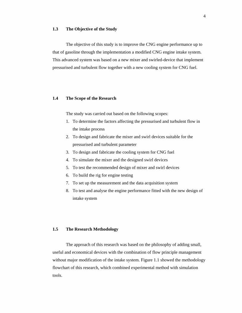
1.3 The Objective of the Study
The objective of this study is to improve the CNG engine performance up to
that of gasoline through the implementation a modified CNG engine intake system.
This advanced system was based on a new mixer and swirled-device that implement
pressurised and turbulent flow together with a new cooling system for CNG fuel.
1.4 The Scope of the Research
The study was carried out based on the following scopes:
1. To determine the factors affecting the pressurised and turbulent flow in
the intake process
2. To design and fabricate the mixer and swirl devices suitable for the
pressurised and turbulent parameter
3. To design and fabricate the cooling system for CNG fuel
4. To simulate the mixer and the designed swirl devices
5. To test the recommended design of mixer and swirl devices
6. To build the rig for engine testing
7. To set up the measurement and the data acquisition system
8. To test and analyse the engine performance fitted with the new design of
intake system
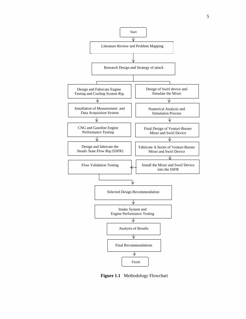
1.5 The Research Methodology
The approach of this research was based on the philosophy of adding small,
useful and economical devices with the combination of flow principle management
without major modification of the intake system. Figure 1.1 showed the methodology
flowchart of this research, which combined experimental method with simulation
tools.
5
Figure 1.1 Methodology Flowchart
Research Design and Strategy of attack
Analysis of Results
Selected Design Recommendation
Intake System and Engine Performance Testing
Start
Final Recommendations
Finish
Literature Review and Problem Mapping
Design of Swirl device and Simulate the Mixer
Design and Fabricate Engine Testing and Cooling System Rig
Installation of Measurement and Data Acquisition System
Numerical Analysis and Simulation Process
CNG and Gasoline Engine Performance Testing
Final Design of Venturi-Burner Mixer and Swirl Device
Design and fabricate the Steady State Flow Rig (SSFR)
Fabricate A Series of Venturi-Burner Mixer and Swirl Device
Flow Validation Testing Install the Mixer and Swirl Device into the SSFR

6
The literature review concentrated on the state of art of the CNG fuel and
engine research. The problem-solution map of the CNG fuelled engine research was
then developed. The next step was divided into two parts: the experimental works;
and design and simulation processes. Experimental part included designed and
fabricated the engine testing experimental rig and CNG fuel cooling system;
instrumentation of the measurement system and running the engine performance test
for both gasoline and CNG mode. The validation flow rig test bed, known as steady
state flow rig test (SSFR) was then constructed.
Simultaneously, the design and simulation steps were initiated. The CNG
mixer was designed, simulated and then analysed. The Star CD software with the
finite volume method with SIMPLE algorithm used in this simulation process.
Moreover, the swirl device was then designed based on variable geometrical
computation. The recommended mixer and swirl were then fabricated.
Subsequently, a series of recommended mixer and swirl-device were validated in the
SSFR. The final recommended design was then fabricated and introduced into the
intake system.
1.6 Thesis Organisation
Chapter 2 presents a literature review of the state of the arts effort relating to
advanced intake system for optimum CNG fuelled engine performance. Beginning
with the automotive trends in implementing alternative fuels, a problem-map solution
in the CNG engine technology was demonstrated. The literature on the flow
management in the intake system as a tool to improve the CNG engine performance
was elaborated. The factors affecting the development of the optimum mixer and
swirl device were reported.
Chapter 3 describes the approach on designing the mixer and swirl device.
Starting from the design and with testing the mixers, then analysing the results. The
simulation stage was then proceed.

7
Chapter 4 explains the validation of mixer design. Experimental results on
effect of various inlet and outlet angles and number of holes on the specified
parameters were presented and discussed.
Chapter 5 depicts a validation process of the mixer and swirl device.
Description on the Steady State Flow Rig (SSFR) and the procedures on validating
process are presented. The visualisation results were also examined. The operational
process of the cooling system for CNG fuel was also explained. The technique in
characterised the CNG engine temperature profiles was also presented. The results
was then analysed in term of heat rejection to coolant.
Chapter 6 sets up a comprehensive coverage on the methodology to perform
an advanced intake system. Detail of experimental design, procedures and
instrumentations were demonstrated. Depiction on the data acquisition system with
its sensor and its software were also provided.
Chapter 7 demonstrated the results and discussion on the effect of advanced
intake system on the engine performance. The indicator diagram, pressure rise inside
the cylinder and the ROHR were analysed for various combination of mixer and
swirl device.
Chapter 8 is the general conclusions and a description of suggestion for future
research.

195
reduced operational cost on the vehicle. As much of RM 4,306 per year can be saved
through implementation of the CNG system.
In the overall, the study has provided a simpler, cheaper and effective
alternative to improve the CNG engine performance.
8.2 Recommendations
The advanced intake system in this study can be further improved by
focusing on the swirl device that can create turbulent without blocking the air
passage into the combustion chamber. A combination studies on intake and
combustion system in the CNG engine is a possible option that has potential to
further improve CNG engine performance.

REFERENCES
AIAA Standard Series (1998). AIAA Guide for the Verification and Validation of
Computational Fluid Dynamics Simulations Reston, VA, USA, AIAA G-077-
1998.
Aldrich B. and Chandler C. (1997). The ABCs of AFVs – A Guide to Alternative Fuel
Vehicles. 4th ed. Sacramento, CA: The California Energy Commission. 53-54.
Ali, Y., M.A. Hanna, and J.E. Borg. (1996). Effect of alternative diesel fuels on heat
release curves for Cummins N14-410 diesel engine. Trans. of the ASAE, 39(2):
407-414.
Alkidas, A.C. and Suh, In-Soo (1991). The Effects of Intake Flow Configuration on
the Heat Release and Heat Transfer Characteristics of a Single Cylinder Four
Valve DI Diesel Engine. Society of Automotive Engineers (SAE) Paper 910296.
Alternative Fuel Data Centre (1996). What are the characteristic of alternative fuel?
Frequently Asked Question on alternative Fuel. Washington: US Department of
Energy. 1-2.
Ando, H. (1996). Combustion Control Technologies for Gasoline Engines. ImechE
Seminar Publication, S433/001/96: 3-15.
Andrew, A.E. and Bradley, D.(1975). The burning velocity of methane-air mixtures.
Combustion and Flame, 24: 275-288
APEC Secretariat (2000). The Role of Petroleum Based and Alternative Transport
Fuels in Reducing Emissions in The APEC Region. Energy Working Group
197
Project EWG 04/99. Singapore: APEC Expert Group on Clean Fossil Energy. 13-
65.
Aston, J.G.L. (1991). Computational Fluid Dynamic without Complex Mathematics:
the Advantage for Thermofluids Education. Proc. ImechE vol. 205: 11-24.
Benek, J.A., E.M. Kraft, and R.F. Lauer, (1998). Validation Issues for Engine -
Airframe Integration. AIAA Journal, Vol. 36, No. 5: 759-764.
Blaxill, H., Qowning, J. Seabrok, J. and Fry, M. (1999). A Parametric Approach to
Spark-Ignition Engine Inlet-Port Design. Society of Automotive Engineers (SAE).
Paper No. 1999-01-0555: 1-6.
Brekken, M. and Durbin, E. (1998). An analysis of the True Efficiency of Alternative
Vehicle Power plants and Alternative Fuels: State of Alternative Fuel
Technologies 1998, Society of Automotive Engineers (SAE). Paper SP-1365:
127-140.
Bo Y. X. and Furuyama M. (1997). Visualization of natural gas-air mixing flow in
the mixer of a CNG vehicle. JSAE Review 18 (1977): 57-82.
Bundu, M.M. (1998). Investigation of the Performance of a Spark Ignition Engine
with Gaseous Fuels. Dalhousie University-Daltech: Master Thesis: 69.
Callister, J.R., Timothi, C.M., and Albert, R.G. (1997). The Design of Automobile
and Racing Car Cooling System. Society of Automotive Engineers (SAE). Paper
No. 971835.
Chapman, K.S. and Brentano, T. (2000). Engine Air Flow Prediction Algorithm.
Manhattan: National Gas Machinery Laboratory. p.20-21.
Cyro, Industries (2001). Working with Acrylite Acrylic Sheet. Rockaway, NJ 07866
Crowther D.A.J. (1996). Natural gas—Just the ticket. ImechE Conference
Transaction, Conference on Bus and Coach, C513/001/96: 109-119.

198
DeCicco, John (2000). It’s Not (Just). Technology, It’s the Market (stupid!).
Washington DC: American Council for an Energy Efficient Economy. 6-7.
Dent, J.C and Chen, A. (1994). An Investigation of Steady Flow Through a Curved
Inlet Port. Society of Automotive Engineers (SAE). Paper No. 940522.
Dietrich, C.F. (1973). Uncertainty, Calibration and Probability, London: Adam
Hilger.
Duan, S.Y. (1996). Using Natural Gas in Engines: Laboratory experience with the
use of natural gas fuel in IC engines. IMechE Seminar Publication S410/005/96:
39-46.
EON (Edaran Otomobil Nasional) Berhad (2003). Chairman Statement. In Annual
Report Year 2002. Kuala Lumpur: Edaran Otomobil Nasional Berhad. 29-30.
Edward, M. (1998). Environmental Vehicles: Competition for the Car of the Future.
London: World Economy Council. 8-11.
Einwall, P. and Johansson, B. (1997). Combustion Chambers for Supercharged
Natural Gas Engines. Society of Automotive Engineers (SAE). Paper No. 970221:
408-433.
Eng, E. (1998). Acura GS-R Header Test. Import Tuner. Fall 1998. 1-2.
Evan, R.L., Blaszczyk, J., and Matys, P. (1996). An Experimental and Numerical
Study of Combustion Chamber Design for Lean-Burn Natural Gas Engines.
Society of Automotive Engineers SAE Paper 961672: 15-21.
Ferguson, Colin R. and Kirkpatrick T. (2001). Internal Combustion engines Applied
Thermosciences. New York: John Wiley and Sons. 213.
Figliola, R.S. and Beasley, D.E. (1995). Theory and Design for Mechanical
Measurement. Canada: John Wiley and Sons.
Fitzgerald, N (2001). Micro-Gas Turbine Engine Ejector-Mixer Design and Testing.
Final Report No 16.621 MIT Turbine Gas Laboratory. 9-11.
199
Floch, A., Frank, J.V. and Ahmed, A. (1995). Comparison of the Effects of Intake-
Generated Swirl and Tumble on Turbulence Characteristics in a 4-valve Engine.
Society of Automotive Engineers SAE Paper 952457: 69-84.
Freidman, M., Powel, K., Hutwagner, L., Graham, L. and Teague, W. (2001). Impact
of Changes in Transportation and Community Behaviors during the 1996
Summer Olympic Games in Atlanta on Air Quality and Childhood Asthma.
Journal of The American Medical Association, vol. 285, February: 897-905.
Garcia, S. (2001). Air Pollution Impacts and Reduction Strategies. Southwestern
Oklahoma State University: Undergraduate Thesis.
Gasparetti M, Paone, N and Tomasini E.P (1996). Laser Doppler Techniques For
The Combined Measurement Of Inlet Flow And Valve Motion In IC Engines.
Measurement Science Technology 7: 576-591.
Gorman, T. (2003). Has the Gas Car a Future? London: World Economy Council.
2-3.
Goto, Y. and Narusawa, K. (1996). Combustion Stabilization of a Spark Ignition
Natural Gas Engine. JSAE Review 17 (1996), p. 251-258.
Guibet, J.C., Faure-Birchem and Levy, R.H. (1999). Fuel and Engines: technology,
Energy and Environment Volume 2. Paris: Institute Francais du Petrole
Publications: 55.
Hardman, K. (1994). Turbocharged, spark ignition, two-stroke engine. Society of
Automotive Engineers SAE Paper 942529
Heuvell, S.L., Van Steenhoven, A.A. and Baert, R.S.G. (1997). Three Dimensional
Calculations and Laser Velocimetry Validation of Steady State Port Valve
Cylinder Flow. Proceedings of the 7th International Conference on Laser
Anemometry - Advances and Applications (ICOLA'97), Karlsruhe, Germany.
Heywood J. (1988). Internal Combustion Engines Fundamentals. Singapore: Mc
Graw Hill International Edition, Automotive Technologies Series.

200
Holman, J.P (1994). Experimental Methods for Engineers. 6th Ed. Singapore: Mc
Graw Hill. 7.
IANGV (2003). International Statistic. New Zealand: International Association for
Natural Gas Vehicle.
IMPCO (1998). Material Handling and Industrial Engine Gaseous Fuel Training
Textbook. Cerritos, CA.: IMPCO Technologies Inc. 92-94.
International Standard (1989). Reciprocating Internal Combustion Engines-
Performance- Part 3: Test Measurements. ISO 3046-3: 1989 (E)
Japanese Industrial Standard (1982). Engine Power Test Code for Road Vehicles JIS
Japan, Japanese Standard Association D 1001-1982.
Johansson, B., and Olsson, K. (1995). Combustion Chambers for Natural Gas SI
Engines Part I: Fluid Flow and Combustion. Society of Automotive Engineers
Paper No. 950469: 374-385.
Karim, G.A, and Wierzba, I. (1983). Comparative Studies of Methane and Propane
as Fuels for Spark Ignition and Compression Ignition Engines. Society of
Automotive Engineers Paper No. 831196.
Kato, K., Igarashi, K., Masuda, M., Otsubo, K., Yasuda, A., Takeda, K., and Sato, T.
(1999). Development of Engine for Natural Gas Vehicle. Society of Automotive
Engineers SAE Paper 1999-01-0574:
Kawashima, J., Ogawa, H. and Tsuru, Y. (1998). Research on a variable swirl
intake port for 4-valve, high-speed DI diesel engines. Society of Automotive
Engineers SAE Paper 982680
Kays, W.M. and London, A.L. (1998). Compact Heat Exchanger. 3rd ed., Krieger
Publishing.
Kompas, Newspaper, Mobil-mobil Baru Triwulan Terakhir Tahun 2001. 23rd
October, 2001

201
Kong, H. and Woods, R.L. (1992). Tuning of intake manifold of an internal
combustion engine using fluid transmission line dynamics. Society of
Automotive Engineers SAE Paper 920685
Kubesh, J.T., Podnar, D.J., Gugliemo, K.H., and McCaw, D. (1995). Development of
an Electronically-Controlled Natural Gas-Fuelled John Deere Power Tech 8.1L
Engine. Society of Automotive Engineers SAE 951940: 788-795.
Kuleshov, A.S (2003). Simulation of interaction of fuel jets with an air swirl and
walls. Research Report on Moscow State Technological University, Piston
Engine Department (E-2): 1-12.
Kunzli, N., Kaiser, R., and Medina, S. (2000). Public-health Impact of Outdoor and
Traffic-related air Pollution: A European Assessment. The Lancet, vol. 356,
September: 795-801.
Kurs, Henk (1993). Numerical Simulation And Experimental Verification Of DI
Diesel Intake Port Designs. Proceeding of the 4th Int. Conf. on Vehicle and
Traffic Systems Technology. June 16-18. Strasbourg..
Lapetz J., Beitler J., Fulton B., LeRoux M., LeRoux J., Peters E., Roman L., Walsh
R. and Wolff W. (1995). Fords 1996 Crown Victoria Dedicated Natural Gas
Vehicle, Society of Automotive Engineers SAE 95: 2083-2091.
Mardani Ali Sera and Rosli Abu Bakar (2001). The Comparison Study On 1.5 L
Engine Performance And Emission Using Gasoline And Natural Gas Fuel.
Proceedings of the Malaysian Science and Technology Congress 2001, Melaka.
Mardani Ali Sera (2002). Experimental Report. Fakulti Kejuruteraan Mekanikal,
Universiti Teknologi Malaysia
Mardani Ali Sera, Rosli Abu Bakar and Sin Kwan Leong (2003). CNG Engine
Performance Improvement Strategy Through Advanced Intake System. Society
of Automotive Engineers (SAE) Paper No. 2003-01-1937.
Maxwell T.T. and Jones J.C. (1995). Alternative Fuels: Emissions, Economics and
Performance. USA: SAE Inc. .17-35.

202
Mayers, D. P., Bourn G. S., Hedrick J. C. and Kubesh J. T. (1997). Evaluation of Six
Natural Gas Combustion System for LNG Locomotive Applications, Society of
Automotive Engineers SAE Paper 972967:1531-1543.
Mustaffa bin Tek (2003). Control of Smoke Emissions In Malaysia. Kuala Lumpur:
Road Transport Department Malaysia. 3-4.
Nakamura, H., Motoyama, H. and Kiyota, Y. (1991). Passenger Car Engines for 21st
Century. Society of Automotive Engineers SAE 911908:1703-1729.
Nylun and Lawson (2000). Exhaust Emission From Natural Gas Vehicle. Aucland,
New Zealand: International Association for Natural Gas Vehicle. 81-82.
Obert, E.F. (1973). Internal Combustion Engines and Air Pollution. New York:
Harper& Row Publisher, Inc.
Omori, S., Iwachido, K., Motomochi, M. and Hirako, O. (1991). Effect of Intake
Port Flow Pattern on the In Cylinder Tumbling Air Flow in Multi Valve SI
Engine. Society of Automotive Engineers SAE Paper 910477: 729
Oullette, P., Mtui P.L., and Hill, P.G. (1998). Numerical Simulation of Directly
Injected Natural Gas and Pilot Diesel Fuel in a Two Stroke Compression Ignition
Engine. State of Alternative Fuel Technologies Society of Automotive Engineers
SP-136, SAE 981400: 141-153.
Park. K.A (1995). Effect of Inlet shapes of a Critical Venturi Nozzles on Discharge
Coefficient Flow Mass Inst. Vol. 6 No. 1: 15-19.
Petronas NGV (2000). Automotive Fuel 2000. Kuala Lumpur. 1-6.
Plint, M. and Martyr, A. (1999). Engine Testing Theory and Practice. Second ed.
London: Butterworth-Heinemann.190-193.
Poulton, M.L. (1994). Alternative Engines for Road Vehicles. Southampton, UK:
Computational Mechanics Publications.

203
Pulkrabek, W.W. (1997) Engineering Fundamentals of The Internal Combustion
Engine. New Jersey, USA: Prentice-Hall Inc. 166-186.
Purcell, R.C. (2000). The Future of Automotive Technology. Advanced Technology
Vehicles, Proceedings of the National Petrochemical & Refiners Association
Annual Meeting, March 27. San Antonio, Texas.
Randolph, A. (1990). Method of Processing Cylinder Pressure Transducer Signals to
Maximise Data Accuracy Society of Automotive Engineers SAE Paper 900170:
191-219.
Rosli Abu Bakar, Mardani Ali Sera and Wong Hong Mun (2001a). Heat Transfer
Analysis In Cooling System of a CNG Fuelled SI Engine. Proceedings of the
BICET, October 9-11. Brunei
Rosli Abu Bakar, Mardani Ali Sera and Wong Hong Mun (2001b). Towards The
Implementation Of CNG Engine: A Literature Review Approach To Problems
And Solutions. Proceedings of the BSME-ASME International Conference on
Thermal Engineering. December 31. Dhaka
Rosli Abu Bakar and Mardani Ali Sera (2001c). The Realization Of Optimum CNG
Engine: It’s Implication On Engine Design. Proceedings of Advances in
Malaysian Energy Research (AMER 2001), October 19. UKM Bangi.
Rosli Abu Bakar , Sin Kwan Leong, Mardani Ali Sera (2003). Effects of Swirl
Device in a Compressed Natural Gas (CNG). Proceedings of the 3rd
International Conference on Recent Advances in Material, Mineral and
Environment (RAMM), Oct. 2003, Penang.
Rosli Abu Bakar, Mardani Ali Sera, Srithar a/l Rajoo and Sin Kwan Leong (2002a).
Study On Engine and Heat Transfer Characteristics of a CNG And Gasoline
Fuelled EFI Engine, Proceedings of the 6th Asia Pacific International Symposium
on Combustion and Energy Utilization, May 20-22. Kuala Lumpur.
Rosli Abu Bakar, Azhar Abdul Aziz and Mardani Ali Sera (2002b), Effect of Air
Fuel Mixer Design on Engine Performance and Exhaust Emission of A CNG

204
Fuelled Vehicles, Proceedings of the 2nd World Engineering Conference (WEC),
July 22-25. Sarawak.
Royo, R, José Corberán, and Antonio Pérez (1994). Optimal Design of the Intake
System in 4-S I.C.E. Society of Automotive Engineers SAE Paper 940210: 1-10.
Saxena, M. (1995). Development of a dual-intake two-stroke engine for two-wheeler
application. Society of Automotive Engineers SAE Paper 951786
Seong, S.K and Sung, S.K. (1995). Effects of Swirl and Spark plug Shape on
Combustion Characteristic in a High Speed Single Shot Visualised SI Engine.
Society of Automotive Engineers SAE Paper 951003.
Shindo, S. and Brask, O. (1969). A Smoke Generator for Low Speed Wind Tunnels.
Technical note No. 69-1, University of Washington, USA: 1-10.
Sierra, Instrument (2000). Sierra 820 Series Top-Trak Mass Flow Meters:
Instruction Manual. Amsterdam.
Star-CD (1999). Computational Fluid Dynamics Software STAR-CD Version 3.10
Methodology, Japan: Computational Dynamics Limited. 1-1.
Stone, R. (1999). Introduction to Internal Combustion Engines 3rd ed. Warrendale,
Pa.: Society of Automotive Engineers.150.
Stratton, S.D. (1996). The design and development of natural gas powered midi bus.
C513/025/96, Proceedings of the IMechE Conference Transaction, Conference
on Bus and Coach ’96, London, 121-130.
Stratton, D.G., Stringer, R.E. and Taylor S.R.G. (1965). Engine Cooling System
Design and Development. ImechE. Proc. 1965-1966, vol. 180, part 2A,
Automobile Division, London, 221-235.
Suga, T., Knight, B. and Arai, S. (1997). Near-Zero Emissions Natural Gas Vehicle
Honda Civic GX. Society of Automotive Engineers SAE Paper 972643: 782-791.

205
SUTP (Sustainable Urban Transportation Project) (2000). Feasibility Study for CNG
Microbuses. SUTP Publication, Surabaya, 19-20.
Swain, M.R., Yusuf, M.J., Dulger, Z., and Swain, M.N. (1993). The Effect of
Hydrogen Addition on Natural Gas Engine Operation. Society of Automotive
Engineers SAE Paper 932775.
Swearingen, C. (1999). Choosing the Best Flowmeter. Chemical Engineering (7/99
issue), New York: Mc Graw-Hill, Inc.
Tallio, K.V., Tobis, B. J. and Selamet, A. (1993). The application of steady-flow
loss correlations to intake manifold design. Society of Automotive Engineers
SAE Paper 930608.
Tilagone, R., Monnier, G., Chaouche, A., Baguelin, Y., and Chauveron D.S. (1996).
Development of a High Efficiency, Low Emission SI-CNG Bus Engine. Society
of Automotive Engineers SAE Paper 961080.
Tunestal, P., Wilcust, M., Lee, A.T. and Hendrick, J.K (1999). In-Cylinder
Measurement for Engine Cold-Start Control. Proceedings of the 1999 IEEE
Internal Conference on Control Applications. August 22-27: Kohala Coast-Island
of Hawaii, Hawaii, USA: p.460-464.
Tunestal, P (2001). Estimation of the In-Cylinder Air/Fuel Ratio of an Internal
Combustion Engine by the use of Pressure Sensor. Lund University: Sweden:
PhD Thesis.
Urushihara, T, Muruyama, T., Takagi, Y. and Lee, K.H. (1995). Turbulence and
Cycle- by-Cycle Velocity Generated by Swirl and Tumble Flow and Their
Effects on Combustion. Society of Automotive Engineers SAE Paper 950813:
157-163.
Vermiglio E, Jenskins, T., Kleliszewski, M., Lapetz, J., Povinger, B., Willey, R.,
Herber, J., Sahutske, K., (1997). Ford’s SULEV Dedicated Natural Gas Trucks.
Society of Automotive Engineers SAE Paper 971662: 2421-2429

206
Vitale, S.(1998). A Physics-based Design Model for Turbulent Reaction Rates in a
Natural Gas Fuelled Internal Combustion Engine. Polytechnic University: PhD.
Thesis.
Walsh, M.P. (1999). Motor Vehicle Pollution Control: Global Progress and
Remaining Problems. Proceeding of the 1st International Conference on Health
Effects of Vehicle Emissions. February 16-17. London: 3-14.
Warsi, Z.V.A. (1981). Conservation Form of the Navier-Stokes Equations in General
Non-Steady Coordinates. Proceedings of AIAA J., 19. 240-242.
Yossefi, D., Maskell, S. J., Ashcroft, S. J. and Belmont, M. R. (2000). Ignition
source characteristics for natural-gas-burning vehicle engines. Proc. ImechE vol.
214 Part D, D05998: 171 – 178
Yufeng, L., Lili, L., Junfeng, X., Xiaohui, G., Shuliang, L. and Sidu X. (2000).
Effect of Combination and Orientation of Intake Port on Swirl Motion in Four
Valve DI Diesel Engines. Society of Automotive Engineers SAE Paper 2000-01-
1823.
Zhang, D. and Hill, P.G. (1996). Effect of Swirl on Combustion in a Short
Cylindrical Chamber. Combustion and Flame 106: 318-332
Zhao, H. and Landomatos, N. (2001). Engine Combustion Instrumentation and
Diagnostics. Warrendale, Pa: Society of Automotive Engineers.70-71.