Embed Size (px)
Citation preview
Missouri University of Science and Technology Missouri University of Science and Technology
Scholars' Mine Scholars' Mine
American Iron and Steel Institute (AISI) Specifications, Standards, Manuals and Research Reports (1946 - present)
Wei-Wen Yu Cold-Formed Steel Library
01 Mar 2021
Development of CUFSM Hole Module and Design Tables for the Development of CUFSM Hole Module and Design Tables for the
Cold-Formed Steel Cross-Sections With Typical Web Holes in AISI Cold-Formed Steel Cross-Sections With Typical Web Holes in AISI
D100 D100
Committee on Specifications for the Design of Cold-Formed Steel Structural Members
Follow this and additional works at: https://scholarsmine.mst.edu/ccfss-aisi-spec
Part of the Structural Engineering Commons
Recommended Citation Recommended Citation Committee on Specifications for the Design of Cold-Formed Steel Structural Members, "Development of CUFSM Hole Module and Design Tables for the Cold-Formed Steel Cross-Sections With Typical Web Holes in AISI D100" (2021). American Iron and Steel Institute (AISI) Specifications, Standards, Manuals and Research Reports (1946 - present). 226. https://scholarsmine.mst.edu/ccfss-aisi-spec/226
This Technical Report is brought to you for free and open access by Scholars' Mine. It has been accepted for inclusion in American Iron and Steel Institute (AISI) Specifications, Standards, Manuals and Research Reports (1946 - present) by an authorized administrator of Scholars' Mine. This work is protected by U. S. Copyright Law. Unauthorized use including reproduction for redistribution requires the permission of the copyright holder. For more information, please contact [email protected].
D e v e l o p m e n t o f C U F S M H o l e M o d u l e a n d D e s i g n T a b l e s f o r t h e C o l d -F o r m e d S t e e l C r o s s -S e c t i o n s W i t h T y p i c a l W e b H o l e s i n A I S I D 1 0 0 R E S E A R C H R E P O R T R P 2 1 - 0 2
Committee on Specifications
for the Design of Cold-Formed
Steel Structural Members
re
sear
ch re
port
American Iron and Steel Institute
ii Development of CUFSM Hole Module and Design Tables for the CFS Cross-Sections With Typical Web Holes in AISI D100
DISCLAIMER
The material contained herein has been developed by researchers based on their research findings. The material has also been reviewed by the American Iron and Steel Institute Committee on Specifications for the Design of Cold-Formed Steel Structural Members. The Committee acknowledges and is grateful for the contributions of such researchers.
The material herein is for general information only. The information in it should not be used without first securing competent advice with respect to its suitability for any given application. The publication of the information is not intended as a representation or warranty on the part of the American Iron and Steel Institute, or of any other person named herein, that the information is suitable for any general or particular use or of freedom from infringement of any patent or patents. Anyone making use of the information assumes all liability arising from such use.
Copyright 2021 American Iron and Steel Institute

Development of CUFSM Hole Module and Design Tables for the CFS Cross-Sections With Typical Web Holes in AISI D100 iii
PREFACE
This report summarizes the effort to develop a simple hole module to perform elastic buckling analysis to obtain the design parameters needed for DSM considering the influence of holes. The hole module requires simple inputs and direct outputs of the elastic buckling information of the local and distortional buckling modes for both gross sections and sections with hole influences.
The excel file can be downloaded via the link below, which contains the nominal local and
distortional buckling strengths of members with web holes for those cross-sections listed in AISI D100, Cold-Formed Steel Design Manual:
(https://www.dropbox.com/s/3dlnmgy9zryfisd/D100_Sections%20with%20holes_V1.xlsx?dl=0 )
A stand-alone software can be downloaded using the link below. This software can be used to determine the local and distortional buckling strengths for any C- or Z-section members with web holes:
(https://www.dropbox.com/sh/2shja16awvz7qe8/AAA_zx_xfTNw2FJAYC0e00bla?dl=0 )
AISI Small Project Fellowship Research Report
Development of CUFSM Hole Module and Design Tables for the Cold-Formed Steel Cross-Sections With Typical Web Holes in AISI D100
Damir Akchurin
Undergraduate Researcher
Department of Engineering
The SUNY Polytechnic Institute
Utica, NY
Zhanjie Li
Associate Professor
Department of Engineering
The SUNY Polytechnic Institute
Utica, NY
July 2020
Contents Introduction .................................................................................................................................................. 1
The hole module function ............................................................................................................................ 2
Material properties ................................................................................................................................... 3
Section dimensions .................................................................................................................................... 3
C/Z Template ............................................................................................................................................. 4
Web hole information ............................................................................................................................... 4
Loading ...................................................................................................................................................... 4
Analyze ...................................................................................................................................................... 4
Outputs ..................................................................................................................................................... 5
Analysis background .................................................................................................................................... 8
Critical buckling and nominal design strengths of C/Z sections with typical holes ................................... 9
References: ................................................................................................................................................. 10
Appendices: ................................................................................................................................................ 11
Example I: Lipped C-section With Web Perforations – Fully Braced Section – Direct Strength Method ................................................................................................................................................................ 11
Example II: Lipped Z-section With Web Perforations – Fully Braced Section – Direct Strength Method ................................................................................................................................................................ 18
1
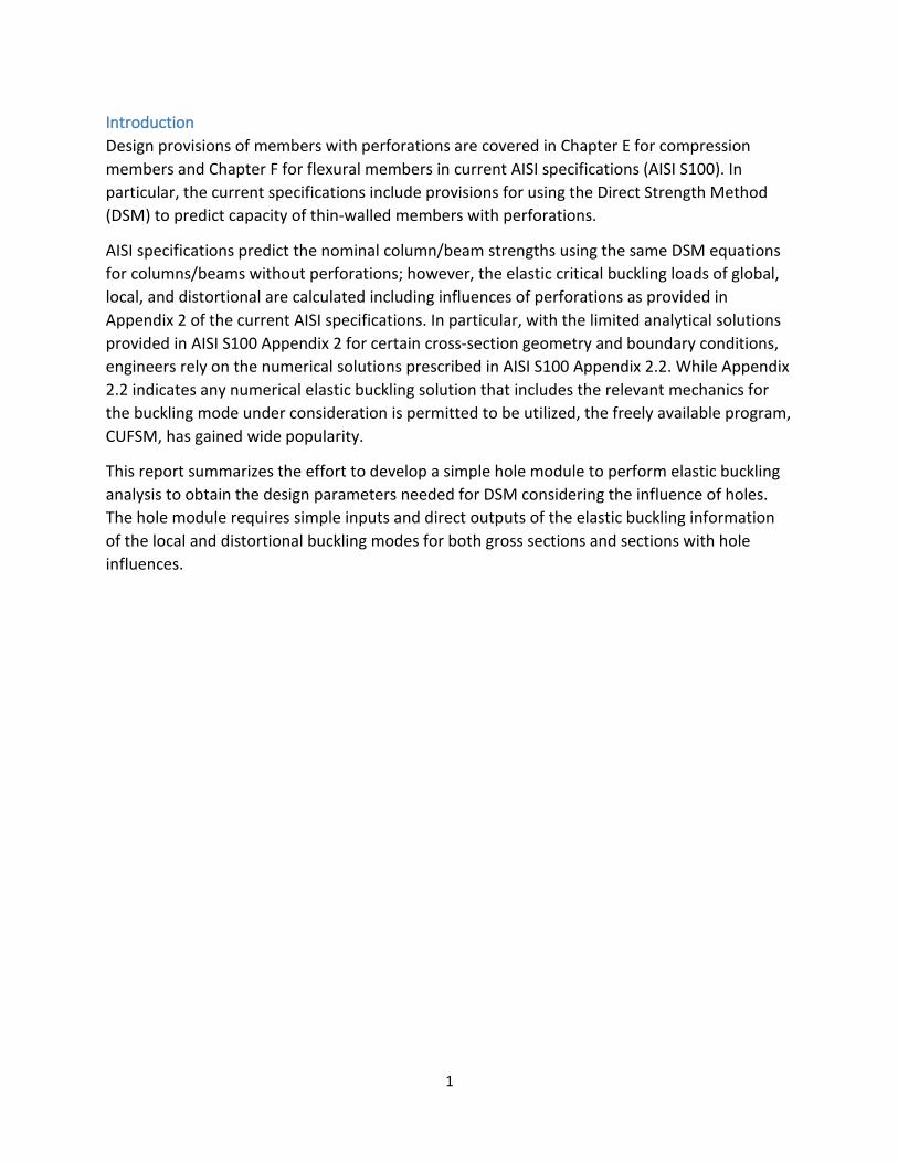
Introduction Design provisions of members with perforations are covered in Chapter E for compression members and Chapter F for flexural members in current AISI specifications (AISI S100). In particular, the current specifications include provisions for using the Direct Strength Method (DSM) to predict capacity of thin-walled members with perforations.
AISI specifications predict the nominal column/beam strengths using the same DSM equations for columns/beams without perforations; however, the elastic critical buckling loads of global, local, and distortional are calculated including influences of perforations as provided in Appendix 2 of the current AISI specifications. In particular, with the limited analytical solutions provided in AISI S100 Appendix 2 for certain cross-section geometry and boundary conditions, engineers rely on the numerical solutions prescribed in AISI S100 Appendix 2.2. While Appendix 2.2 indicates any numerical elastic buckling solution that includes the relevant mechanics for the buckling mode under consideration is permitted to be utilized, the freely available program, CUFSM, has gained wide popularity.
This report summarizes the effort to develop a simple hole module to perform elastic buckling analysis to obtain the design parameters needed for DSM considering the influence of holes. The hole module requires simple inputs and direct outputs of the elastic buckling information of the local and distortional buckling modes for both gross sections and sections with hole influences.
2
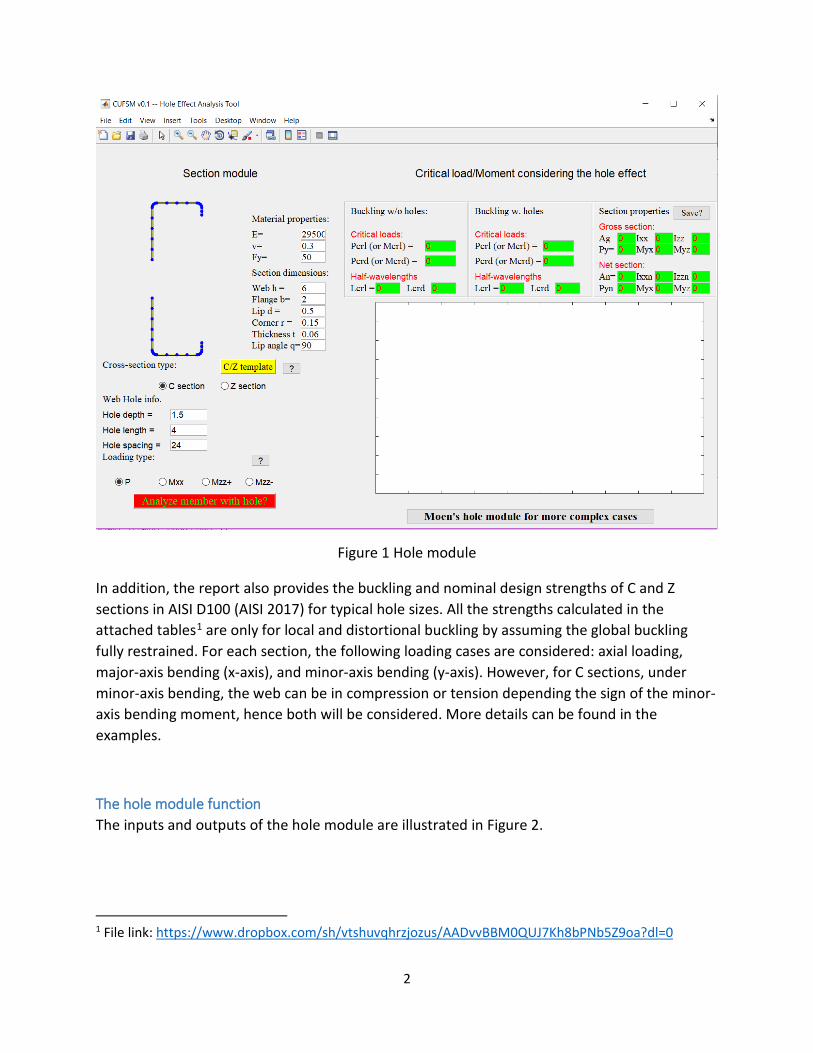
Figure 1 Hole module
In addition, the report also provides the buckling and nominal design strengths of C and Z sections in AISI D100 (AISI 2017) for typical hole sizes. All the strengths calculated in the attached tables1 are only for local and distortional buckling by assuming the global buckling fully restrained. For each section, the following loading cases are considered: axial loading, major-axis bending (x-axis), and minor-axis bending (y-axis). However, for C sections, under minor-axis bending, the web can be in compression or tension depending the sign of the minor-axis bending moment, hence both will be considered. More details can be found in the examples.
The hole module function The inputs and outputs of the hole module are illustrated in Figure 2.
1 File link: https://www.dropbox.com/sh/vtshuvqhrzjozus/AADvvBBM0QUJ7Kh8bPNb5Z9oa?dl=0
3
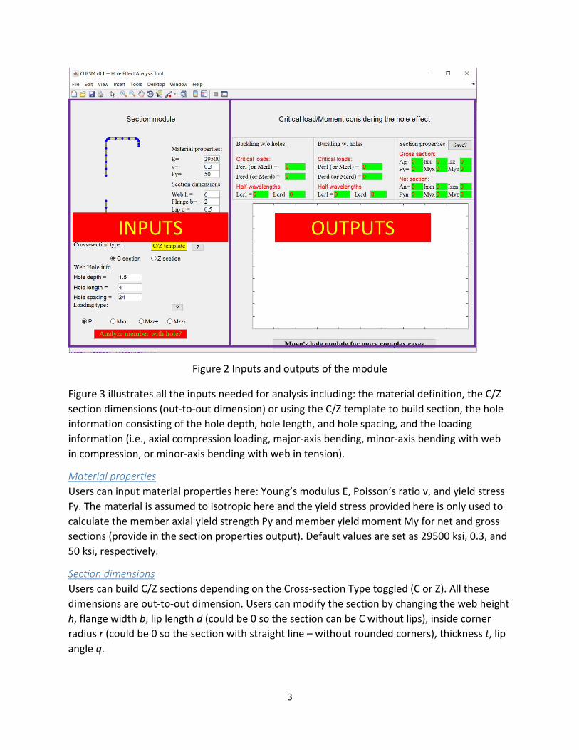
Figure 2 Inputs and outputs of the module
Figure 3 illustrates all the inputs needed for analysis including: the material definition, the C/Z section dimensions (out-to-out dimension) or using the C/Z template to build section, the hole information consisting of the hole depth, hole length, and hole spacing, and the loading information (i.e., axial compression loading, major-axis bending, minor-axis bending with web in compression, or minor-axis bending with web in tension).
Material properties Users can input material properties here: Young’s modulus E, Poisson’s ratio v, and yield stress Fy. The material is assumed to isotropic here and the yield stress provided here is only used to calculate the member axial yield strength Py and member yield moment My for net and gross sections (provide in the section properties output). Default values are set as 29500 ksi, 0.3, and 50 ksi, respectively.
Section dimensions Users can build C/Z sections depending on the Cross-section Type toggled (C or Z). All these dimensions are out-to-out dimension. Users can modify the section by changing the web height h, flange width b, lip length d (could be 0 so the section can be C without lips), inside corner radius r (could be 0 so the section with straight line – without rounded corners), thickness t, lip angle q.
4
C/Z Template This will allow users to build C/Z sections using templates in CUFSM, particularly users can find the Steel Framing Industry Association (SFIA) section database. Users can also use the function provided inside the template to switch from U.S. customary units to SI units.
Web hole information Only web holes are considered. The holes are assumed to be evenly spaced. The hole depth is the height of the hole in the web, the hole length is the length of the hole along the member length, and the hole spacing is the center-to-center space between the holes along the member.
Loading The typical loading conditions can be considered as
• P: Axial loading (compression) • Mxx: Bending about x-axis • Mzz+: Bending about y-axis (Web in compression) • Mzz-: Bending about y-axis (Web in tension)
Analyze With all of these are appropriately set up, the users can hit the ‘Analyze member with hole?’ push button to analyze the member.

5
Figure 3 Inputs of the module for analysis
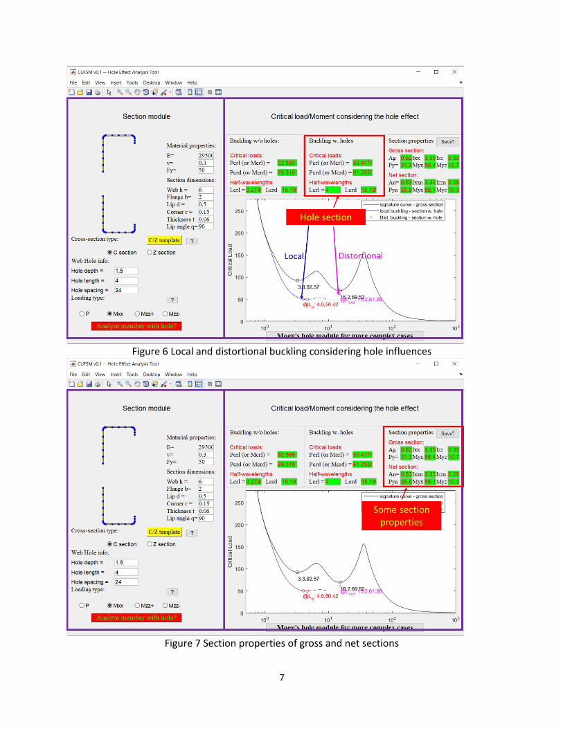
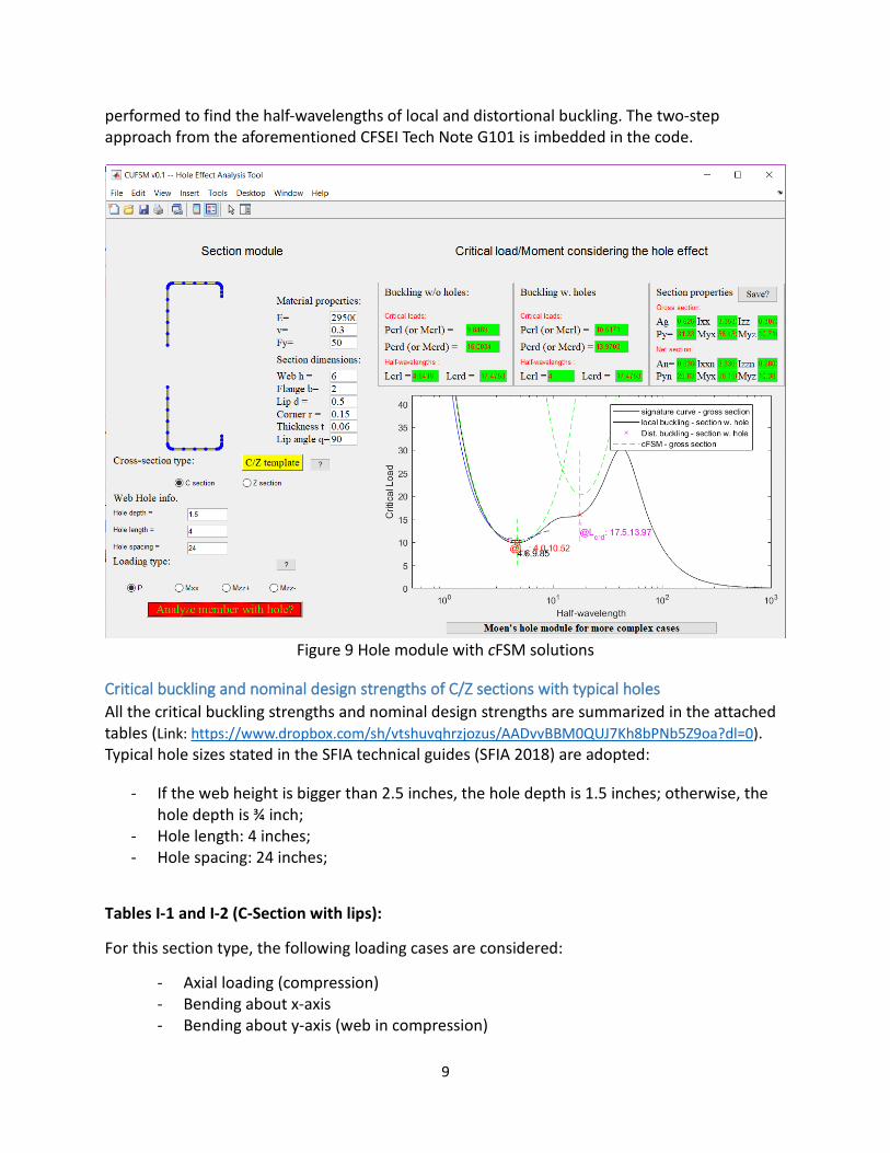
Outputs Once the analysis is done, the module will populate the output fields as shown in Figures 4-7, including the local and distortional buckling half-wavelengths and strengths for the section without holes and with holes and also the sectional properties. The figure plots the following curves: signature curve of the gross section, local buckling with hole influence, distortional buckling with hole influence. In the case where there is no distinct local minima from the signature curve, the constrained Finite Strip Method (cFSM) analysis of a straight-line model (without rounded corners) will be plotted as well. The cFSM analysis results provide the half-wavelengths of local and distortional buckling modes.

6
Figure 4 Output results from analysis
Figure 5 Local and distortional buckling of Gross section
7
Figure 6 Local and distortional buckling considering hole influences
Figure 7 Section properties of gross and net sections

8
In case users want to have all the section properties from CUFSM analysis, the ‘Save?’ push button can output all the properties to a text file.
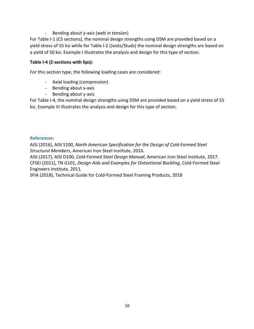
Analysis background While the above illustrations show the analysis following the recommended procedure of using numerical analysis in AISI S100 Appendix 2.2, there is one approach adopted in the module to overcome the challenges of no distinct minima. To overcome the potential challenge of the “non- unique minima” from the CUFSM elastic buckling analysis, where either or both minima related to local and distortional buckling is “indistinct” in the finite strip method (FSM) solution, a two-step approach in CFSEI Tech Note G101 (CFSEI, 2011) is adopted. The approach also provides the opportunity to automate the design process utilizing the computational tools such as CUFSM with DSM.
In calculating the buckling loads, a conventional FSM model considering rounded corners is used. If the resulting signature curve has unique minima, no further analysis is conducted. If the signature curve does not have unique minima, cFSM solutions with straight line model are used to identify the appropriate buckling half-wavelength, Lcr. The critical load Pcr (or moment Mcr) at the associated Lcr is then determined from the conventional FSM analysis.
Figure 8 Signature curve augmented with pure mode cFSM solution and illustration of the proposed FSM@cFSM-Lcr solution to identifying non-unique minima
Figure 9 shows a case of no distinct minima from the FSM analysis and cFSM analyses are
100 101 102 1030
5
10
15
20
25
30
35
40
4.1,4.47
X: FSM@cFSM-Lcr=4.09 , Mcrl=4.47
X: FSM@cFSM-Lcr=19.31 , Mcrd=9.24
Half-wave length
Crit
ical
Loa
d M
c r
FSM solution, rounded corner modelcFSM solution, straight-line model
, kip
s-in
, inch
Distortional X
Local X
9
performed to find the half-wavelengths of local and distortional buckling. The two-step approach from the aforementioned CFSEI Tech Note G101 is imbedded in the code.
Figure 9 Hole module with cFSM solutions
Critical buckling and nominal design strengths of C/Z sections with typical holes All the critical buckling strengths and nominal design strengths are summarized in the attached tables (Link: https://www.dropbox.com/sh/vtshuvqhrzjozus/AADvvBBM0QUJ7Kh8bPNb5Z9oa?dl=0). Typical hole sizes stated in the SFIA technical guides (SFIA 2018) are adopted:
- If the web height is bigger than 2.5 inches, the hole depth is 1.5 inches; otherwise, the hole depth is ¾ inch;
- Hole length: 4 inches; - Hole spacing: 24 inches;
Tables I-1 and I-2 (C-Section with lips):
For this section type, the following loading cases are considered:
- Axial loading (compression) - Bending about x-axis - Bending about y-axis (web in compression)
10
- Bending about y-axis (web in tension) For Table I-1 (CS sections), the nominal design strengths using DSM are provided based on a yield stress of 55 ksi while for Table I-2 (Joists/Studs) the nominal design strengths are based on a yield of 50 ksi. Example I illustrates the analysis and design for this type of section.
Table I-4 (Z-sections with lips):
For this section type, the following loading cases are considered:
- Axial loading (compression) - Bending about x-axis - Bending about y-axis
For Table I-4, the nominal design strengths using DSM are provided based on a yield stress of 55 ksi. Example III illustrates the analysis and design for this type of section.
References: AISI (2016), AISI S100, North American Specification for the Design of Cold-Formed Steel Structural Members, American Iron Steel Institute, 2016. AISI (2017), AISI D100, Cold-Formed Steel Design Manual, American Iron Steel Institute, 2017. CFSEI (2011), TN G101, Design Aids and Examples for Distortional Buckling, Cold-Formed Steel Engineers Institute, 2011. SFIA (2018), Technical Guide for Cold-Formed Steel Framing Products, 2018

11
Appendices:
Example I: Lipped C-section With Web Perforations – Fully Braced Section – Direct Strength Method
Given: 1. Steel: Fy = 33 ksi 2. Section: 550S162-33 as shown above Required: 1. Nominal compressive strength Pn 2. Nominal flexural strength Mn for bending about x-axis (major-axis bending) 3. Nominal flexural strength Mn for bending about y-axis (minor-axis bending, web in tension) 4. Nominal flexural strength Mn for bending about y-axis (minor-axis bending, web in compression) Solution: The limits of applicability for the Direct Strength Method contained in Table B4.1-1 must be satisfied. The following gross section properties are determined from Table I-2: A = 0.327 in.2 Sx = 0.530 in.3 Sy = 0.0952 in.3
1. Nominal compressive strength Pn:
a. The gross and net section yield strengths are calculated with the section property calculator in CUFSM. To determine the net section properties in CUFSM, assign a thickness of zero to the elements at the location of the perforations, but do not delete them. Assuming 33 ksi steel, Py = 10.8 kips and Pynet = 9.1 kips.
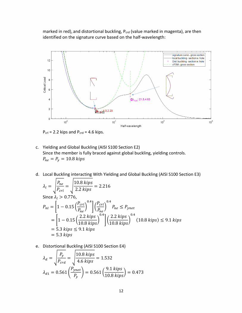
b. A finite strip analysis of the 550S162-33 section in compression is performed according to AISI S100 Appendix 2.2. The minima corresponding to local buckling, Pcrl (value
12
marked in red), and distortional buckling, Pcrd (value marked in magenta), are then identified on the signature curve based on the half-wavelength:
Pcrl = 2.2 kips and Pcrd = 4.6 kips.
c. Yielding and Global Buckling (AISI S100 Section E2) Since the member is fully braced against global buckling, yielding controls. 𝑃𝑃𝑛𝑛𝑛𝑛 = 𝑃𝑃𝑦𝑦 = 10.8 𝑘𝑘𝑘𝑘𝑘𝑘𝑘𝑘
d. Local Buckling interacting With Yielding and Global Buckling (AISI S100 Section E3)
𝜆𝜆𝑙𝑙 = �𝑃𝑃𝑛𝑛𝑛𝑛𝑃𝑃𝑐𝑐𝑐𝑐𝑙𝑙
= �10.8 𝑘𝑘𝑘𝑘𝑘𝑘𝑘𝑘2.2 𝑘𝑘𝑘𝑘𝑘𝑘𝑘𝑘
= 2.216
Since 𝜆𝜆𝑙𝑙 > 0.776,
𝑃𝑃𝑛𝑛𝑙𝑙 = �1 − 0.15 �𝑃𝑃𝑐𝑐𝑐𝑐𝑙𝑙𝑃𝑃𝑛𝑛𝑛𝑛
�0.4
� �𝑃𝑃𝑐𝑐𝑐𝑐𝑙𝑙𝑃𝑃𝑛𝑛𝑛𝑛
�0.4
𝑃𝑃𝑛𝑛𝑛𝑛 ≤ 𝑃𝑃𝑦𝑦𝑛𝑛𝑛𝑛𝑦𝑦
= �1 − 0.15 �2.2 𝑘𝑘𝑘𝑘𝑘𝑘𝑘𝑘
10.8 𝑘𝑘𝑘𝑘𝑘𝑘𝑘𝑘�0.4
� �2.2 𝑘𝑘𝑘𝑘𝑘𝑘𝑘𝑘
10.8 𝑘𝑘𝑘𝑘𝑘𝑘𝑘𝑘�0.4
(10.8 𝑘𝑘𝑘𝑘𝑘𝑘𝑘𝑘) ≤ 9.1 𝑘𝑘𝑘𝑘𝑘𝑘𝑘𝑘
= 5.3 𝑘𝑘𝑘𝑘𝑘𝑘𝑘𝑘 ≤ 9.1 𝑘𝑘𝑘𝑘𝑘𝑘𝑘𝑘 = 5.3 𝑘𝑘𝑘𝑘𝑘𝑘𝑘𝑘
e. Distortional Buckling (AISI S100 Section E4)
𝜆𝜆𝑑𝑑 = �𝑃𝑃𝑦𝑦𝑃𝑃𝑐𝑐𝑐𝑐𝑑𝑑
= �10.8 𝑘𝑘𝑘𝑘𝑘𝑘𝑘𝑘4.6 𝑘𝑘𝑘𝑘𝑘𝑘𝑘𝑘
= 1.532
𝜆𝜆𝑑𝑑1 = 0.561�𝑃𝑃𝑦𝑦𝑛𝑛𝑛𝑛𝑦𝑦𝑃𝑃𝑦𝑦
� = 0.561 �9.1 𝑘𝑘𝑘𝑘𝑘𝑘𝑘𝑘
10.8 𝑘𝑘𝑘𝑘𝑘𝑘𝑘𝑘� = 0.473
13
𝜆𝜆𝑑𝑑2 = 0.561 �14.0�𝑃𝑃𝑦𝑦𝑛𝑛𝑛𝑛𝑦𝑦𝑃𝑃𝑦𝑦
�0.4
− 13.0� = 0.561 �14.0 �9.1 𝑘𝑘𝑘𝑘𝑘𝑘𝑘𝑘
10.8 𝑘𝑘𝑘𝑘𝑘𝑘𝑘𝑘�0.4
− 13.0� = 0.041
Since 𝜆𝜆𝑑𝑑 > 𝜆𝜆𝑑𝑑2 and 𝜆𝜆𝑑𝑑 > 0.561,
𝑃𝑃𝑛𝑛𝑑𝑑 = �1 − 0.25�𝑃𝑃𝑐𝑐𝑐𝑐𝑑𝑑𝑃𝑃𝑦𝑦
�0.6
� �𝑃𝑃𝑐𝑐𝑐𝑐𝑑𝑑𝑃𝑃𝑦𝑦
�0.6
𝑃𝑃𝑦𝑦
= �1 − 0.25 �4.6 𝑘𝑘𝑘𝑘𝑘𝑘𝑘𝑘
10.8 𝑘𝑘𝑘𝑘𝑘𝑘𝑘𝑘�0.6
� �4.6 𝑘𝑘𝑘𝑘𝑘𝑘𝑘𝑘
10.8 𝑘𝑘𝑘𝑘𝑘𝑘𝑘𝑘�0.6
(10.8 𝑘𝑘𝑘𝑘𝑘𝑘𝑘𝑘)
= 5.5 𝑘𝑘𝑘𝑘𝑘𝑘𝑘𝑘
f. Nominal compressive strength (AISI S100 Section E1) 𝑃𝑃𝑛𝑛 = min(𝑃𝑃𝑛𝑛𝑛𝑛 ,𝑃𝑃𝑛𝑛𝑙𝑙 ,𝑃𝑃𝑛𝑛𝑑𝑑) = min(10.8 𝑘𝑘𝑘𝑘𝑘𝑘𝑘𝑘, 5.3 𝑘𝑘𝑘𝑘𝑘𝑘𝑘𝑘, 5.5 𝑘𝑘𝑘𝑘𝑘𝑘𝑘𝑘) = 5.5 𝑘𝑘𝑘𝑘𝑘𝑘𝑘𝑘 Local buckling controls. The nominal compressive strength of the fully braced section is therefore 5.3 kips.
2. Nominal flexural strength Mn for bending about x-axis:
a. The gross and net section yield strengths are calculated with the section property calculator in CUFSM. To determine the net section properties in CUFSM, assign a thickness of zero to the elements at the location of the perforations, but do not delete them. Assuming 33 ksi steel, My=17.6 kip*in and Mynet=17.5 kip*in.
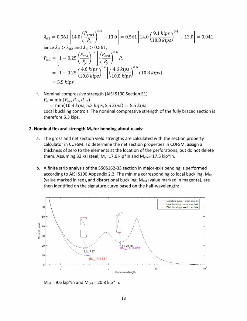
b. A finite strip analysis of the 550S162-33 section in major-axis bending is performed according to AISI S100 Appendix 2.2. The minima corresponding to local buckling, Mcrl (value marked in red), and distortional buckling, Mcrd (value marked in magenta), are then identified on the signature curve based on the half-wavelength:
Mcrl = 9.6 kip*in and Mcrd = 20.8 kip*in.
14
c. Yielding and Global Buckling (AISI S100 Section F2) Since the member is fully braced against global buckling, yielding controls. 𝑀𝑀𝑛𝑛𝑛𝑛 = 𝑀𝑀𝑦𝑦 = 17.6 𝑘𝑘𝑘𝑘𝑘𝑘 ∗ 𝑘𝑘𝑖𝑖
d. Local Buckling interacting With Yielding and Global Buckling (AISI S100 Section F3)
𝜆𝜆𝑙𝑙 = �𝑀𝑀𝑛𝑛𝑛𝑛
𝑀𝑀𝑐𝑐𝑐𝑐𝑙𝑙= �
17.6 𝑘𝑘𝑘𝑘𝑘𝑘 ∗ 𝑘𝑘𝑖𝑖9.6 𝑘𝑘𝑘𝑘𝑘𝑘 ∗ 𝑘𝑘𝑖𝑖
= 1.354
Since 𝜆𝜆𝑙𝑙 > 0.776,
𝑀𝑀𝑛𝑛𝑙𝑙 = �1 − 0.15 �𝑀𝑀𝑐𝑐𝑐𝑐𝑙𝑙
𝑀𝑀𝑛𝑛𝑛𝑛�0.4
� �𝑀𝑀𝑐𝑐𝑐𝑐𝑙𝑙
𝑀𝑀𝑛𝑛𝑛𝑛�0.4
𝑀𝑀𝑛𝑛𝑛𝑛 ≤ 𝑀𝑀𝑦𝑦𝑛𝑛𝑛𝑛𝑦𝑦
= �1 − 0.15 �9.6 𝑘𝑘𝑘𝑘𝑘𝑘 ∗ 𝑘𝑘𝑖𝑖
17.6 𝑘𝑘𝑘𝑘𝑘𝑘 ∗ 𝑘𝑘𝑖𝑖�0.4
� �9.6 𝑘𝑘𝑘𝑘𝑘𝑘 ∗ 𝑘𝑘𝑖𝑖
17.6 𝑘𝑘𝑘𝑘𝑘𝑘 ∗ 𝑘𝑘𝑖𝑖�0.4
(17.6 𝑘𝑘𝑘𝑘𝑘𝑘 ∗ 𝑘𝑘𝑖𝑖) ≤ 17.5 𝑘𝑘𝑘𝑘𝑘𝑘 ∗ 𝑘𝑘𝑖𝑖
= 12.2 𝑘𝑘𝑘𝑘𝑘𝑘 ∗ 𝑘𝑘𝑖𝑖 ≤ 17.5 𝑘𝑘𝑘𝑘𝑘𝑘 ∗ 𝑘𝑘𝑖𝑖 = 12.2 𝑘𝑘𝑘𝑘𝑘𝑘 ∗ 𝑘𝑘𝑖𝑖
e. Distortional Buckling (AISI S100 Section F4)
𝜆𝜆𝑑𝑑 = �𝑀𝑀𝑦𝑦
𝑀𝑀𝑐𝑐𝑐𝑐𝑑𝑑= �
17.6 𝑘𝑘𝑘𝑘𝑘𝑘 ∗ 𝑘𝑘𝑖𝑖20.8 𝑘𝑘𝑘𝑘𝑘𝑘 ∗ 𝑘𝑘𝑖𝑖
= 0.920
𝜆𝜆𝑑𝑑1 = 0.673�𝑀𝑀𝑦𝑦𝑛𝑛𝑛𝑛𝑦𝑦
𝑀𝑀𝑦𝑦�3
= 0.673 �17.5 𝑘𝑘𝑘𝑘𝑘𝑘 ∗ 𝑘𝑘𝑖𝑖17.6 𝑘𝑘𝑘𝑘𝑘𝑘 ∗ 𝑘𝑘𝑖𝑖
�3
= 0.662
𝜆𝜆𝑑𝑑2 = 0.673 �1.7�𝑀𝑀𝑦𝑦𝑛𝑛𝑛𝑛𝑦𝑦
𝑀𝑀𝑦𝑦�2.7
− 0.7� = 0.673 �1.7 �17.5 𝑘𝑘𝑘𝑘𝑘𝑘 ∗ 𝑘𝑘𝑖𝑖17.6 𝑘𝑘𝑘𝑘𝑘𝑘 ∗ 𝑘𝑘𝑖𝑖
�2.7
− 0.7� = 0.671
Since 𝜆𝜆𝑑𝑑 > 𝜆𝜆𝑑𝑑2 and 𝜆𝜆𝑑𝑑 > 0.673,
𝑀𝑀𝑛𝑛𝑑𝑑 = �1 − 0.22�𝑀𝑀𝑐𝑐𝑐𝑐𝑑𝑑
𝑀𝑀𝑦𝑦�0.5
� �𝑀𝑀𝑐𝑐𝑐𝑐𝑑𝑑
𝑀𝑀𝑦𝑦�0.5
𝑀𝑀𝑦𝑦
= �1 − 0.22 �20.8 𝑘𝑘𝑘𝑘𝑘𝑘 ∗ 𝑘𝑘𝑖𝑖17.6 𝑘𝑘𝑘𝑘𝑘𝑘 ∗ 𝑘𝑘𝑖𝑖
�0.5
� �20.8 𝑘𝑘𝑘𝑘𝑘𝑘 ∗ 𝑘𝑘𝑖𝑖17.6 𝑘𝑘𝑘𝑘𝑘𝑘 ∗ 𝑘𝑘𝑖𝑖
�0.5
(17.6 𝑘𝑘𝑘𝑘𝑘𝑘 ∗ 𝑘𝑘𝑖𝑖)
= 14.6 𝑘𝑘𝑘𝑘𝑘𝑘 ∗ 𝑘𝑘𝑖𝑖
f. Nominal flexural strength (AISI S100 Section F1) 𝑀𝑀𝑛𝑛 = min(𝑀𝑀𝑛𝑛𝑛𝑛 ,𝑀𝑀𝑛𝑛𝑙𝑙 ,𝑀𝑀𝑛𝑛𝑑𝑑) = min(17.6 𝑘𝑘𝑘𝑘𝑘𝑘 ∗ 𝑘𝑘𝑖𝑖, 12.2 𝑘𝑘𝑘𝑘𝑘𝑘 ∗ 𝑘𝑘𝑖𝑖, 14.6 𝑘𝑘𝑘𝑘𝑘𝑘 ∗ 𝑘𝑘𝑖𝑖) = 12.2 𝑘𝑘𝑘𝑘𝑘𝑘 ∗ 𝑘𝑘𝑖𝑖 Local buckling controls. The nominal flexural strength for x-axis bending of the fully braced section is therefore 12.2 kip*in.
3. Nominal flexural strength Mn for bending about y-axis with web in compression:
a. The gross and net section yield strengths are calculated with the section property calculator in CUFSM. To determine the net section properties in CUFSM, assign a

15
thickness of zero to the elements at the location of the perforations, but do not delete them. Assuming 33 ksi steel, My=3.2 kip*in and Mynet=3.1 kip*in.
b. A finite strip analysis of the 550S162-33 section in major-axis bending is performed according to AISI S100 Appendix 2.2. The minima corresponding to local buckling, Mcrl (value marked in red), is then identified on the signature curve based on the half-wavelength:
Mcrl = 1.7 kip*in.
c. Yielding and Global Buckling (AISI S100 Section F2) Since the member is fully braced against global buckling, yielding controls. 𝑀𝑀𝑛𝑛𝑛𝑛 = 𝑀𝑀𝑦𝑦 = 3.2 𝑘𝑘𝑘𝑘𝑘𝑘 ∗ 𝑘𝑘𝑖𝑖
d. Local Buckling interacting With Yielding and Global Buckling (AISI S100 Section F3)
𝜆𝜆𝑙𝑙 = �𝑀𝑀𝑛𝑛𝑛𝑛
𝑀𝑀𝑐𝑐𝑐𝑐𝑙𝑙= �
3.2 𝑘𝑘𝑘𝑘𝑘𝑘 ∗ 𝑘𝑘𝑖𝑖1.7 𝑘𝑘𝑘𝑘𝑘𝑘 ∗ 𝑘𝑘𝑖𝑖
= 1.372
Since 𝜆𝜆𝑙𝑙 > 0.776,
𝑀𝑀𝑛𝑛𝑙𝑙 = �1 − 0.15 �𝑀𝑀𝑐𝑐𝑐𝑐𝑙𝑙
𝑀𝑀𝑛𝑛𝑛𝑛�0.4
� �𝑀𝑀𝑐𝑐𝑐𝑐𝑙𝑙
𝑀𝑀𝑛𝑛𝑛𝑛�0.4
𝑀𝑀𝑛𝑛𝑛𝑛 ≤ 𝑀𝑀𝑦𝑦𝑛𝑛𝑛𝑛𝑦𝑦
= �1 − 0.15 �1.7 𝑘𝑘𝑘𝑘𝑘𝑘 ∗ 𝑘𝑘𝑖𝑖3.2 𝑘𝑘𝑘𝑘𝑘𝑘 ∗ 𝑘𝑘𝑖𝑖
�0.4
� �1.7 𝑘𝑘𝑘𝑘𝑘𝑘 ∗ 𝑘𝑘𝑖𝑖3.2 𝑘𝑘𝑘𝑘𝑘𝑘 ∗ 𝑘𝑘𝑖𝑖
�0.4
(3.2 𝑘𝑘𝑘𝑘𝑘𝑘 ∗ 𝑘𝑘𝑖𝑖) ≤ 3.1 𝑘𝑘𝑘𝑘𝑘𝑘 ∗ 𝑘𝑘𝑖𝑖
= 2.2 𝑘𝑘𝑘𝑘𝑘𝑘 ∗ 𝑘𝑘𝑖𝑖 ≤ 3.1 𝑘𝑘𝑘𝑘𝑘𝑘 ∗ 𝑘𝑘𝑖𝑖 = 2.2 𝑘𝑘𝑘𝑘𝑘𝑘 ∗ 𝑘𝑘𝑖𝑖
e. Nominal flexural strength (AISI S100 Section F1) 𝑀𝑀𝑛𝑛 = min(𝑀𝑀𝑛𝑛𝑛𝑛 ,𝑀𝑀𝑛𝑛𝑙𝑙) = min(3.2 𝑘𝑘𝑘𝑘𝑘𝑘 ∗ 𝑘𝑘𝑖𝑖, 2.2 𝑘𝑘𝑘𝑘𝑘𝑘 ∗ 𝑘𝑘𝑖𝑖) = 2.2 𝑘𝑘𝑘𝑘𝑘𝑘 ∗ 𝑘𝑘𝑖𝑖 Local buckling controls. The nominal flexural strength for x-axis bending with web in compression of the fully braced section is therefore 2.2 kip*in.
16
4. Nominal flexural strength Mn for bending about y-axis with web in tension:
a. The gross and net section yield strengths are calculated with the section property calculator in CUFSM. To determine the net section properties in CUFSM, assign a thickness of zero to the elements at the location of the perforations, but do not delete them. Assuming 33 ksi steel, My=3.2 kip*in and Mynet=3.1 kip*in.
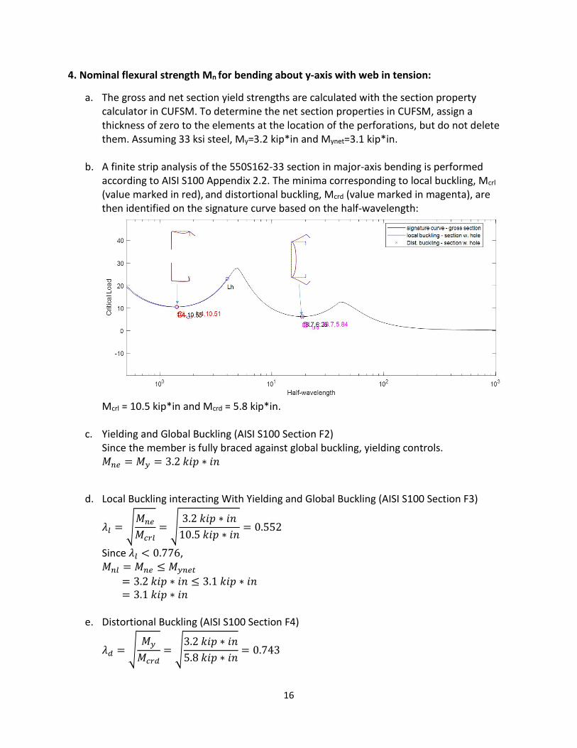
b. A finite strip analysis of the 550S162-33 section in major-axis bending is performed according to AISI S100 Appendix 2.2. The minima corresponding to local buckling, Mcrl (value marked in red), and distortional buckling, Mcrd (value marked in magenta), are then identified on the signature curve based on the half-wavelength:
Mcrl = 10.5 kip*in and Mcrd = 5.8 kip*in.
c. Yielding and Global Buckling (AISI S100 Section F2) Since the member is fully braced against global buckling, yielding controls. 𝑀𝑀𝑛𝑛𝑛𝑛 = 𝑀𝑀𝑦𝑦 = 3.2 𝑘𝑘𝑘𝑘𝑘𝑘 ∗ 𝑘𝑘𝑖𝑖
d. Local Buckling interacting With Yielding and Global Buckling (AISI S100 Section F3)
𝜆𝜆𝑙𝑙 = �𝑀𝑀𝑛𝑛𝑛𝑛
𝑀𝑀𝑐𝑐𝑐𝑐𝑙𝑙= �
3.2 𝑘𝑘𝑘𝑘𝑘𝑘 ∗ 𝑘𝑘𝑖𝑖10.5 𝑘𝑘𝑘𝑘𝑘𝑘 ∗ 𝑘𝑘𝑖𝑖
= 0.552
Since 𝜆𝜆𝑙𝑙 < 0.776, 𝑀𝑀𝑛𝑛𝑙𝑙 = 𝑀𝑀𝑛𝑛𝑛𝑛 ≤ 𝑀𝑀𝑦𝑦𝑛𝑛𝑛𝑛𝑦𝑦 = 3.2 𝑘𝑘𝑘𝑘𝑘𝑘 ∗ 𝑘𝑘𝑖𝑖 ≤ 3.1 𝑘𝑘𝑘𝑘𝑘𝑘 ∗ 𝑘𝑘𝑖𝑖 = 3.1 𝑘𝑘𝑘𝑘𝑘𝑘 ∗ 𝑘𝑘𝑖𝑖
e. Distortional Buckling (AISI S100 Section F4)
𝜆𝜆𝑑𝑑 = �𝑀𝑀𝑦𝑦
𝑀𝑀𝑐𝑐𝑐𝑐𝑑𝑑= �
3.2 𝑘𝑘𝑘𝑘𝑘𝑘 ∗ 𝑘𝑘𝑖𝑖5.8 𝑘𝑘𝑘𝑘𝑘𝑘 ∗ 𝑘𝑘𝑖𝑖
= 0.743
17
𝜆𝜆𝑑𝑑1 = 0.673�𝑀𝑀𝑦𝑦𝑛𝑛𝑛𝑛𝑦𝑦
𝑀𝑀𝑦𝑦�3
= 0.673 �3.1 𝑘𝑘𝑘𝑘𝑘𝑘 ∗ 𝑘𝑘𝑖𝑖3.2 𝑘𝑘𝑘𝑘𝑘𝑘 ∗ 𝑘𝑘𝑖𝑖
�3
= 0.612
𝜆𝜆𝑑𝑑2 = 0.673 �1.7�𝑀𝑀𝑦𝑦𝑛𝑛𝑛𝑛𝑦𝑦
𝑀𝑀𝑦𝑦�2.7
− 0.7� = 0.673 �1.7 �17.5 𝑘𝑘𝑘𝑘𝑘𝑘 ∗ 𝑘𝑘𝑖𝑖17.6 𝑘𝑘𝑘𝑘𝑘𝑘 ∗ 𝑘𝑘𝑖𝑖
�2.7
− 0.7� = 0.656
Since 𝜆𝜆𝑑𝑑 > 𝜆𝜆𝑑𝑑2 and 𝜆𝜆𝑑𝑑 > 0.673,
𝑀𝑀𝑛𝑛𝑑𝑑 = �1 − 0.22�𝑀𝑀𝑐𝑐𝑐𝑐𝑑𝑑
𝑀𝑀𝑦𝑦�0.5
� �𝑀𝑀𝑐𝑐𝑐𝑐𝑑𝑑
𝑀𝑀𝑦𝑦�0.5
𝑀𝑀𝑦𝑦
= �1 − 0.22 �5.8 𝑘𝑘𝑘𝑘𝑘𝑘 ∗ 𝑘𝑘𝑖𝑖3.2 𝑘𝑘𝑘𝑘𝑘𝑘 ∗ 𝑘𝑘𝑖𝑖
�0.5
� �5.8 𝑘𝑘𝑘𝑘𝑘𝑘 ∗ 𝑘𝑘𝑖𝑖3.2 𝑘𝑘𝑘𝑘𝑘𝑘 ∗ 𝑘𝑘𝑖𝑖
�0.5
(3.2 𝑘𝑘𝑘𝑘𝑘𝑘 ∗ 𝑘𝑘𝑖𝑖)
= 3.0 𝑘𝑘𝑘𝑘𝑘𝑘 ∗ 𝑘𝑘𝑖𝑖
f. Nominal flexural strength (AISI S100 Section F1) 𝑀𝑀𝑛𝑛 = min(𝑀𝑀𝑛𝑛𝑛𝑛 ,𝑀𝑀𝑛𝑛𝑙𝑙 ,𝑀𝑀𝑛𝑛𝑑𝑑) = min(3.2 𝑘𝑘𝑘𝑘𝑘𝑘 ∗ 𝑘𝑘𝑖𝑖, 3.1 𝑘𝑘𝑘𝑘𝑘𝑘 ∗ 𝑘𝑘𝑖𝑖, 3.0 𝑘𝑘𝑘𝑘𝑘𝑘 ∗ 𝑘𝑘𝑖𝑖) = 3.0 𝑘𝑘𝑘𝑘𝑘𝑘 ∗ 𝑘𝑘𝑖𝑖 Local buckling controls. The nominal flexural strength for y-axis bending with web in compression of the fully braced section is therefore 3.0 kip*in.
18
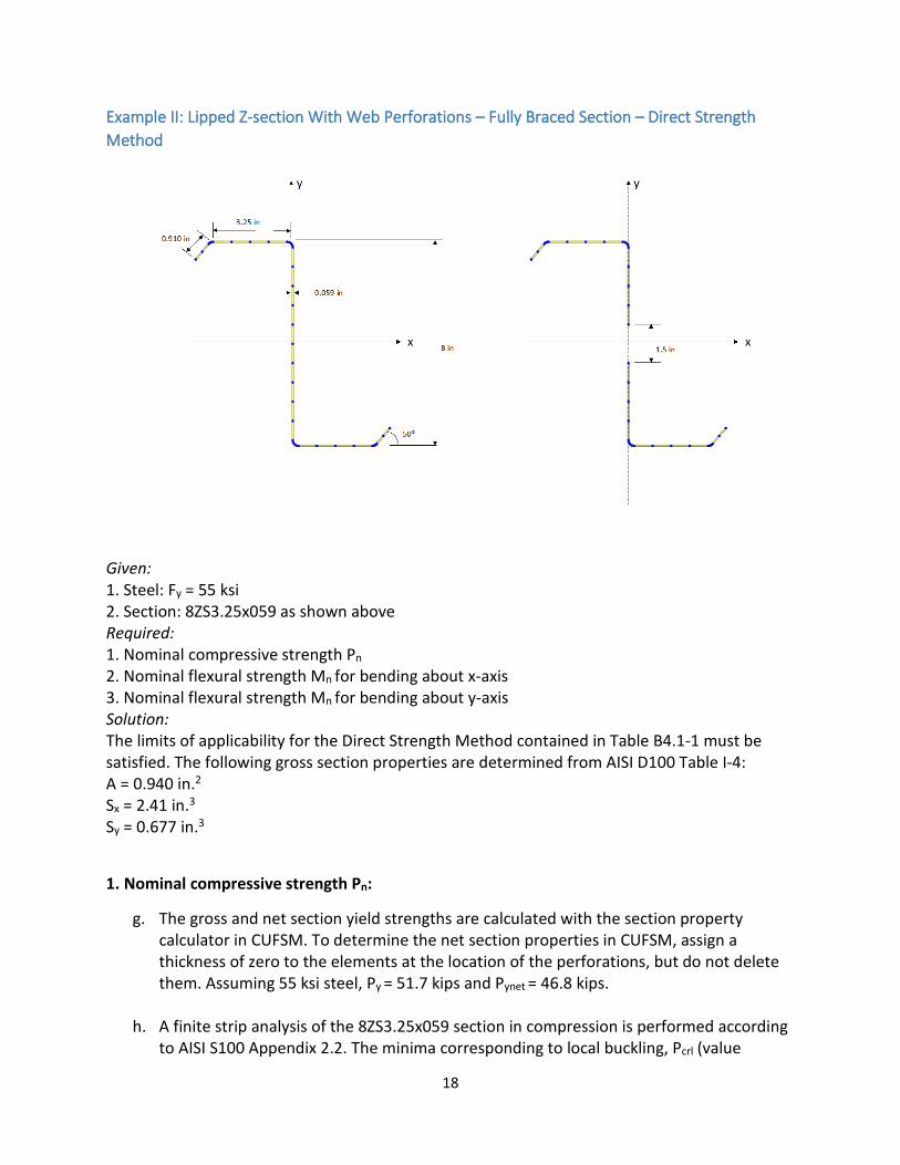
Example II: Lipped Z-section With Web Perforations – Fully Braced Section – Direct Strength Method
Given: 1. Steel: Fy = 55 ksi 2. Section: 8ZS3.25x059 as shown above Required: 1. Nominal compressive strength Pn 2. Nominal flexural strength Mn for bending about x-axis 3. Nominal flexural strength Mn for bending about y-axis Solution: The limits of applicability for the Direct Strength Method contained in Table B4.1-1 must be satisfied. The following gross section properties are determined from AISI D100 Table I-4: A = 0.940 in.2 Sx = 2.41 in.3 Sy = 0.677 in.3
1. Nominal compressive strength Pn:
g. The gross and net section yield strengths are calculated with the section property calculator in CUFSM. To determine the net section properties in CUFSM, assign a thickness of zero to the elements at the location of the perforations, but do not delete them. Assuming 55 ksi steel, Py = 51.7 kips and Pynet = 46.8 kips.
h. A finite strip analysis of the 8ZS3.25x059 section in compression is performed according to AISI S100 Appendix 2.2. The minima corresponding to local buckling, Pcrl (value
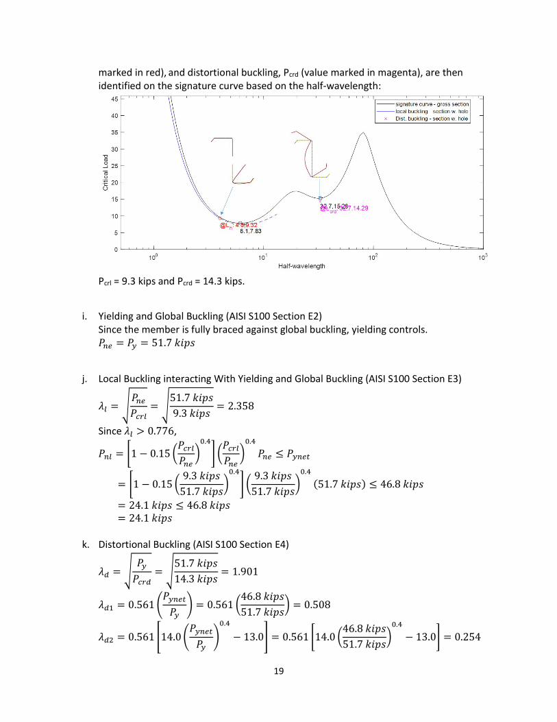
19
marked in red), and distortional buckling, Pcrd (value marked in magenta), are then identified on the signature curve based on the half-wavelength:
Pcrl = 9.3 kips and Pcrd = 14.3 kips.
i. Yielding and Global Buckling (AISI S100 Section E2) Since the member is fully braced against global buckling, yielding controls. 𝑃𝑃𝑛𝑛𝑛𝑛 = 𝑃𝑃𝑦𝑦 = 51.7 𝑘𝑘𝑘𝑘𝑘𝑘𝑘𝑘
j. Local Buckling interacting With Yielding and Global Buckling (AISI S100 Section E3)
𝜆𝜆𝑙𝑙 = �𝑃𝑃𝑛𝑛𝑛𝑛𝑃𝑃𝑐𝑐𝑐𝑐𝑙𝑙
= �51.7 𝑘𝑘𝑘𝑘𝑘𝑘𝑘𝑘9.3 𝑘𝑘𝑘𝑘𝑘𝑘𝑘𝑘
= 2.358
Since 𝜆𝜆𝑙𝑙 > 0.776,
𝑃𝑃𝑛𝑛𝑙𝑙 = �1 − 0.15 �𝑃𝑃𝑐𝑐𝑐𝑐𝑙𝑙𝑃𝑃𝑛𝑛𝑛𝑛
�0.4
� �𝑃𝑃𝑐𝑐𝑐𝑐𝑙𝑙𝑃𝑃𝑛𝑛𝑛𝑛
�0.4
𝑃𝑃𝑛𝑛𝑛𝑛 ≤ 𝑃𝑃𝑦𝑦𝑛𝑛𝑛𝑛𝑦𝑦
= �1 − 0.15 �9.3 𝑘𝑘𝑘𝑘𝑘𝑘𝑘𝑘
51.7 𝑘𝑘𝑘𝑘𝑘𝑘𝑘𝑘�0.4
� �9.3 𝑘𝑘𝑘𝑘𝑘𝑘𝑘𝑘
51.7 𝑘𝑘𝑘𝑘𝑘𝑘𝑘𝑘�0.4
(51.7 𝑘𝑘𝑘𝑘𝑘𝑘𝑘𝑘) ≤ 46.8 𝑘𝑘𝑘𝑘𝑘𝑘𝑘𝑘
= 24.1 𝑘𝑘𝑘𝑘𝑘𝑘𝑘𝑘 ≤ 46.8 𝑘𝑘𝑘𝑘𝑘𝑘𝑘𝑘 = 24.1 𝑘𝑘𝑘𝑘𝑘𝑘𝑘𝑘
k. Distortional Buckling (AISI S100 Section E4)
𝜆𝜆𝑑𝑑 = �𝑃𝑃𝑦𝑦𝑃𝑃𝑐𝑐𝑐𝑐𝑑𝑑
= �51.7 𝑘𝑘𝑘𝑘𝑘𝑘𝑘𝑘14.3 𝑘𝑘𝑘𝑘𝑘𝑘𝑘𝑘
= 1.901
𝜆𝜆𝑑𝑑1 = 0.561�𝑃𝑃𝑦𝑦𝑛𝑛𝑛𝑛𝑦𝑦𝑃𝑃𝑦𝑦
� = 0.561 �46.8 𝑘𝑘𝑘𝑘𝑘𝑘𝑘𝑘51.7 𝑘𝑘𝑘𝑘𝑘𝑘𝑘𝑘
� = 0.508
𝜆𝜆𝑑𝑑2 = 0.561 �14.0�𝑃𝑃𝑦𝑦𝑛𝑛𝑛𝑛𝑦𝑦𝑃𝑃𝑦𝑦
�0.4
− 13.0� = 0.561 �14.0 �46.8 𝑘𝑘𝑘𝑘𝑘𝑘𝑘𝑘51.7 𝑘𝑘𝑘𝑘𝑘𝑘𝑘𝑘
�0.4
− 13.0� = 0.254
20
Since 𝜆𝜆𝑑𝑑 > 𝜆𝜆𝑑𝑑2 and 𝜆𝜆𝑑𝑑 > 0.561,
𝑃𝑃𝑛𝑛𝑑𝑑 = �1 − 0.25�𝑃𝑃𝑐𝑐𝑐𝑐𝑑𝑑𝑃𝑃𝑦𝑦
�0.6
� �𝑃𝑃𝑐𝑐𝑐𝑐𝑑𝑑𝑃𝑃𝑦𝑦
�0.6
𝑃𝑃𝑦𝑦
= �1 − 0.25 �14.3 𝑘𝑘𝑘𝑘𝑘𝑘𝑘𝑘51.7 𝑘𝑘𝑘𝑘𝑘𝑘𝑘𝑘
�0.6
� �14.3 𝑘𝑘𝑘𝑘𝑘𝑘𝑘𝑘51.7 𝑘𝑘𝑘𝑘𝑘𝑘𝑘𝑘
�0.6
(51.7 𝑘𝑘𝑘𝑘𝑘𝑘𝑘𝑘)
= 21.1 𝑘𝑘𝑘𝑘𝑘𝑘𝑘𝑘
l. Nominal compressive strength (AISI S100 Section E1) 𝑃𝑃𝑛𝑛 = min(𝑃𝑃𝑛𝑛𝑛𝑛 ,𝑃𝑃𝑛𝑛𝑙𝑙 ,𝑃𝑃𝑛𝑛𝑑𝑑) = min(51.7 𝑘𝑘𝑘𝑘𝑘𝑘𝑘𝑘, 24.1 𝑘𝑘𝑘𝑘𝑘𝑘𝑘𝑘, 21.1 𝑘𝑘𝑘𝑘𝑘𝑘𝑘𝑘) = 21.1 𝑘𝑘𝑘𝑘𝑘𝑘𝑘𝑘 Distortional buckling controls. The nominal compressive strength of the fully braced section is therefore 21.1 kips.
2. Nominal flexural strength Mn for bending about x-axis:
g. The gross and net section yield strengths are calculated with the section property calculator in CUFSM. To determine the net section properties in CUFSM, assign a thickness of zero to the elements at the location of the perforations, but do not delete them. Assuming 55 ksi steel, My = 133.2 kip*in and Mynet = 133.0 kip*in.
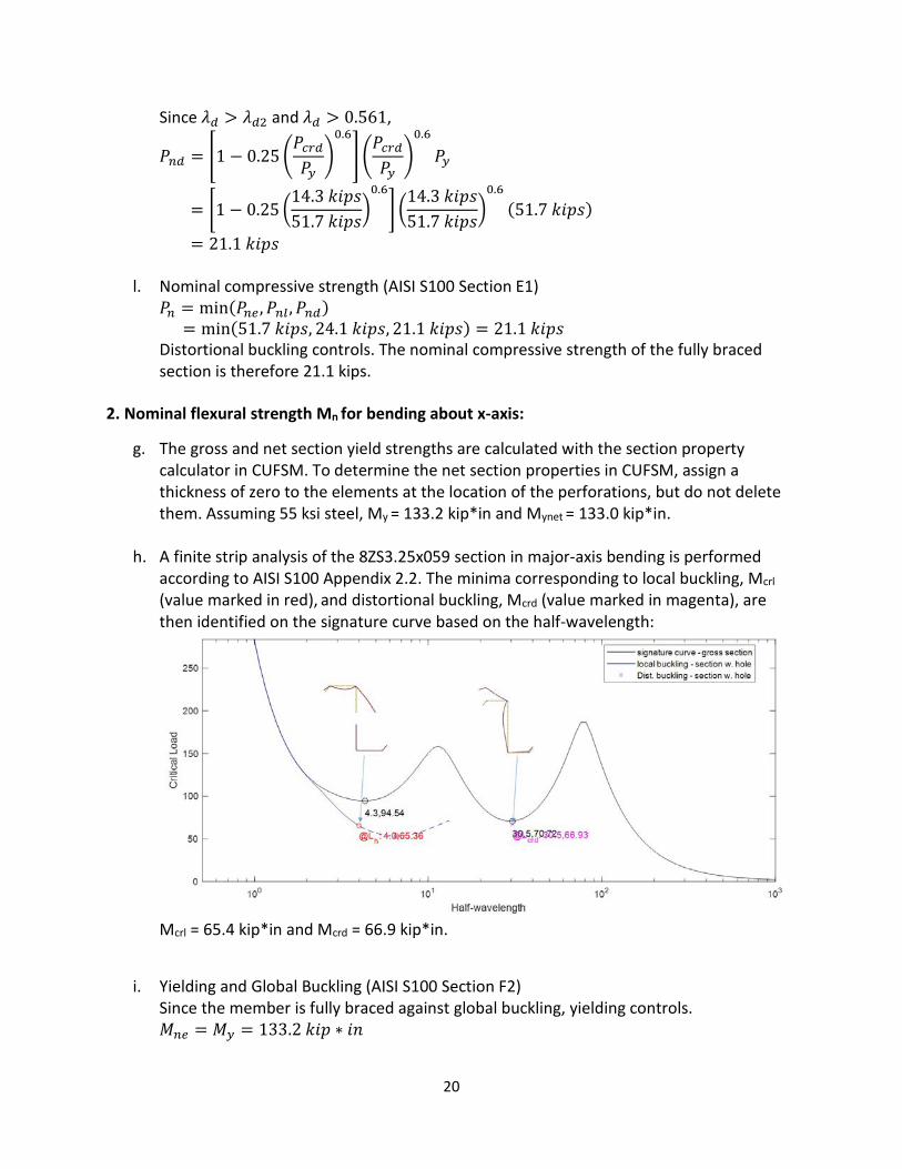
h. A finite strip analysis of the 8ZS3.25x059 section in major-axis bending is performed according to AISI S100 Appendix 2.2. The minima corresponding to local buckling, Mcrl (value marked in red), and distortional buckling, Mcrd (value marked in magenta), are then identified on the signature curve based on the half-wavelength:
Mcrl = 65.4 kip*in and Mcrd = 66.9 kip*in.
i. Yielding and Global Buckling (AISI S100 Section F2) Since the member is fully braced against global buckling, yielding controls. 𝑀𝑀𝑛𝑛𝑛𝑛 = 𝑀𝑀𝑦𝑦 = 133.2 𝑘𝑘𝑘𝑘𝑘𝑘 ∗ 𝑘𝑘𝑖𝑖
21
j. Local Buckling interacting With Yielding and Global Buckling (AISI S100 Section F3)
𝜆𝜆𝑙𝑙 = �𝑀𝑀𝑛𝑛𝑛𝑛
𝑀𝑀𝑐𝑐𝑐𝑐𝑙𝑙= �
133.2 𝑘𝑘𝑘𝑘𝑘𝑘 ∗ 𝑘𝑘𝑖𝑖65.4 𝑘𝑘𝑘𝑘𝑘𝑘 ∗ 𝑘𝑘𝑖𝑖
= 1.427
Since 𝜆𝜆𝑙𝑙 > 0.776,
𝑀𝑀𝑛𝑛𝑙𝑙 = �1 − 0.15 �𝑀𝑀𝑐𝑐𝑐𝑐𝑙𝑙
𝑀𝑀𝑛𝑛𝑛𝑛�0.4
� �𝑀𝑀𝑐𝑐𝑐𝑐𝑙𝑙
𝑀𝑀𝑛𝑛𝑛𝑛�0.4
𝑀𝑀𝑛𝑛𝑛𝑛 ≤ 𝑀𝑀𝑦𝑦𝑛𝑛𝑛𝑛𝑦𝑦
= �1 − 0.15 �65.4 𝑘𝑘𝑘𝑘𝑘𝑘 ∗ 𝑘𝑘𝑖𝑖
133.2 𝑘𝑘𝑘𝑘𝑘𝑘 ∗ 𝑘𝑘𝑖𝑖�0.4
� �65.4 𝑘𝑘𝑘𝑘𝑘𝑘 ∗ 𝑘𝑘𝑖𝑖
133.2 𝑘𝑘𝑘𝑘𝑘𝑘 ∗ 𝑘𝑘𝑖𝑖�0.4
(133.2 𝑘𝑘𝑘𝑘𝑘𝑘 ∗ 𝑘𝑘𝑖𝑖) ≤ 133.0 𝑘𝑘𝑘𝑘𝑘𝑘 ∗ 𝑘𝑘𝑖𝑖
= 88.9 𝑘𝑘𝑘𝑘𝑘𝑘 ∗ 𝑘𝑘𝑖𝑖 ≤ 133.0 𝑘𝑘𝑘𝑘𝑘𝑘 ∗ 𝑘𝑘𝑖𝑖 = 88.9 𝑘𝑘𝑘𝑘𝑘𝑘 ∗ 𝑘𝑘𝑖𝑖
k. Distortional Buckling (AISI S100 Section F4)
𝜆𝜆𝑑𝑑 = �𝑀𝑀𝑦𝑦
𝑀𝑀𝑐𝑐𝑐𝑐𝑑𝑑= �
133.2 𝑘𝑘𝑘𝑘𝑘𝑘 ∗ 𝑘𝑘𝑖𝑖66.9 𝑘𝑘𝑘𝑘𝑘𝑘 ∗ 𝑘𝑘𝑖𝑖
= 1.411
𝜆𝜆𝑑𝑑1 = 0.673�𝑀𝑀𝑦𝑦𝑛𝑛𝑛𝑛𝑦𝑦
𝑀𝑀𝑦𝑦�3
= 0.673 �133.0 𝑘𝑘𝑘𝑘𝑘𝑘 ∗ 𝑘𝑘𝑖𝑖133.2 𝑘𝑘𝑘𝑘𝑘𝑘 ∗ 𝑘𝑘𝑖𝑖
�3
= 0.670
𝜆𝜆𝑑𝑑2 = 0.673 �1.7�𝑀𝑀𝑦𝑦𝑛𝑛𝑛𝑛𝑦𝑦
𝑀𝑀𝑦𝑦�2.7
− 0.7� = 0.673 �1.7 �133.0 𝑘𝑘𝑘𝑘𝑘𝑘 ∗ 𝑘𝑘𝑖𝑖133.2 𝑘𝑘𝑘𝑘𝑘𝑘 ∗ 𝑘𝑘𝑖𝑖
�2.7
− 0.7� = 0.668
Since 𝜆𝜆𝑑𝑑 > 𝜆𝜆𝑑𝑑2 and 𝜆𝜆𝑑𝑑 > 0.673,
𝑀𝑀𝑛𝑛𝑑𝑑 = �1 − 0.22�𝑀𝑀𝑐𝑐𝑐𝑐𝑑𝑑
𝑀𝑀𝑦𝑦�0.5
� �𝑀𝑀𝑐𝑐𝑐𝑐𝑑𝑑
𝑀𝑀𝑦𝑦�0.5
𝑀𝑀𝑦𝑦
= �1 − 0.22 �66.7 𝑘𝑘𝑘𝑘𝑘𝑘 ∗ 𝑘𝑘𝑖𝑖
133.2 𝑘𝑘𝑘𝑘𝑘𝑘 ∗ 𝑘𝑘𝑖𝑖�0.5
� �66.7 𝑘𝑘𝑘𝑘𝑘𝑘 ∗ 𝑘𝑘𝑖𝑖
133.2 𝑘𝑘𝑘𝑘𝑘𝑘 ∗ 𝑘𝑘𝑖𝑖�0.5
(133.2 𝑘𝑘𝑘𝑘𝑘𝑘 ∗ 𝑘𝑘𝑖𝑖)
= 79.6 𝑘𝑘𝑘𝑘𝑘𝑘 ∗ 𝑘𝑘𝑖𝑖
l. Nominal flexural strength (AISI S100 Section F1) 𝑀𝑀𝑛𝑛 = min(𝑀𝑀𝑛𝑛𝑛𝑛 ,𝑀𝑀𝑛𝑛𝑙𝑙 ,𝑀𝑀𝑛𝑛𝑑𝑑) = min(133.2 𝑘𝑘𝑘𝑘𝑘𝑘 ∗ 𝑘𝑘𝑖𝑖, 88.9 𝑘𝑘𝑘𝑘𝑘𝑘 ∗ 𝑘𝑘𝑖𝑖, 79.6 𝑘𝑘𝑘𝑘𝑘𝑘 ∗ 𝑘𝑘𝑖𝑖) = 79.6 𝑘𝑘𝑘𝑘𝑘𝑘 ∗ 𝑘𝑘𝑖𝑖 Distortional buckling controls. The nominal flexural strength for bending about x-axis of the fully braced section is therefore 79.6 kip*in.
3. Nominal flexural strength Mn for bending about y-axis:
f. The gross and net section yield strengths are calculated with the section property calculator in CUFSM. To determine the net section properties in CUFSM, assign a thickness of zero to the elements at the location of the perforations, but do not delete them. Assuming 55 ksi steel, My = 37.4 kip*in and Mynet = 37.4 kip*in.
22
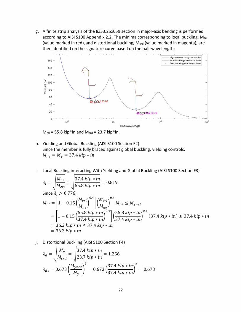
g. A finite strip analysis of the 8ZS3.25x059 section in major-axis bending is performed according to AISI S100 Appendix 2.2. The minima corresponding to local buckling, Mcrl (value marked in red), and distortional buckling, Mcrd (value marked in magenta), are then identified on the signature curve based on the half-wavelength:
Mcrl = 55.8 kip*in and Mcrd = 23.7 kip*in.
h. Yielding and Global Buckling (AISI S100 Section F2) Since the member is fully braced against global buckling, yielding controls. 𝑀𝑀𝑛𝑛𝑛𝑛 = 𝑀𝑀𝑦𝑦 = 37.4 𝑘𝑘𝑘𝑘𝑘𝑘 ∗ 𝑘𝑘𝑖𝑖
i. Local Buckling interacting With Yielding and Global Buckling (AISI S100 Section F3)
𝜆𝜆𝑙𝑙 = �𝑀𝑀𝑛𝑛𝑛𝑛
𝑀𝑀𝑐𝑐𝑐𝑐𝑙𝑙= �
37.4 𝑘𝑘𝑘𝑘𝑘𝑘 ∗ 𝑘𝑘𝑖𝑖55.8 𝑘𝑘𝑘𝑘𝑘𝑘 ∗ 𝑘𝑘𝑖𝑖
= 0.819
Since 𝜆𝜆𝑙𝑙 > 0.776,
𝑀𝑀𝑛𝑛𝑙𝑙 = �1 − 0.15 �𝑀𝑀𝑐𝑐𝑐𝑐𝑙𝑙
𝑀𝑀𝑛𝑛𝑛𝑛�0.4
� �𝑀𝑀𝑐𝑐𝑐𝑐𝑙𝑙
𝑀𝑀𝑛𝑛𝑛𝑛�0.4
𝑀𝑀𝑛𝑛𝑛𝑛 ≤ 𝑀𝑀𝑦𝑦𝑛𝑛𝑛𝑛𝑦𝑦
= �1 − 0.15 �55.8 𝑘𝑘𝑘𝑘𝑘𝑘 ∗ 𝑘𝑘𝑖𝑖37.4 𝑘𝑘𝑘𝑘𝑘𝑘 ∗ 𝑘𝑘𝑖𝑖
�0.4
� �55.8 𝑘𝑘𝑘𝑘𝑘𝑘 ∗ 𝑘𝑘𝑖𝑖37.4 𝑘𝑘𝑘𝑘𝑘𝑘 ∗ 𝑘𝑘𝑖𝑖
�0.4
(37.4 𝑘𝑘𝑘𝑘𝑘𝑘 ∗ 𝑘𝑘𝑖𝑖) ≤ 37.4 𝑘𝑘𝑘𝑘𝑘𝑘 ∗ 𝑘𝑘𝑖𝑖
= 36.2 𝑘𝑘𝑘𝑘𝑘𝑘 ∗ 𝑘𝑘𝑖𝑖 ≤ 37.4 𝑘𝑘𝑘𝑘𝑘𝑘 ∗ 𝑘𝑘𝑖𝑖 = 36.2 𝑘𝑘𝑘𝑘𝑘𝑘 ∗ 𝑘𝑘𝑖𝑖
j. Distortional Buckling (AISI S100 Section F4)
𝜆𝜆𝑑𝑑 = �𝑀𝑀𝑦𝑦
𝑀𝑀𝑐𝑐𝑐𝑐𝑑𝑑= �
37.4 𝑘𝑘𝑘𝑘𝑘𝑘 ∗ 𝑘𝑘𝑖𝑖23.7 𝑘𝑘𝑘𝑘𝑘𝑘 ∗ 𝑘𝑘𝑖𝑖
= 1.256
𝜆𝜆𝑑𝑑1 = 0.673�𝑀𝑀𝑦𝑦𝑛𝑛𝑛𝑛𝑦𝑦
𝑀𝑀𝑦𝑦�3
= 0.673 �37.4 𝑘𝑘𝑘𝑘𝑘𝑘 ∗ 𝑘𝑘𝑖𝑖37.4 𝑘𝑘𝑘𝑘𝑘𝑘 ∗ 𝑘𝑘𝑖𝑖
�3
= 0.673

23
𝜆𝜆𝑑𝑑2 = 0.673 �1.7�𝑀𝑀𝑦𝑦𝑛𝑛𝑛𝑛𝑦𝑦
𝑀𝑀𝑦𝑦�2.7
− 0.7� = 0.673 �1.7 �37.4 𝑘𝑘𝑘𝑘𝑘𝑘 ∗ 𝑘𝑘𝑖𝑖37.4 𝑘𝑘𝑘𝑘𝑘𝑘 ∗ 𝑘𝑘𝑖𝑖
�2.7
− 0.7� = 0.673
Since 𝜆𝜆𝑑𝑑 > 𝜆𝜆𝑑𝑑2 and 𝜆𝜆𝑑𝑑 > 0.673,
𝑀𝑀𝑛𝑛𝑑𝑑 = �1 − 0.22�𝑀𝑀𝑐𝑐𝑐𝑐𝑑𝑑
𝑀𝑀𝑦𝑦�0.5
� �𝑀𝑀𝑐𝑐𝑐𝑐𝑑𝑑
𝑀𝑀𝑦𝑦�0.5
𝑀𝑀𝑦𝑦
= �1 − 0.22 �23.7 𝑘𝑘𝑘𝑘𝑘𝑘 ∗ 𝑘𝑘𝑖𝑖37.4 𝑘𝑘𝑘𝑘𝑘𝑘 ∗ 𝑘𝑘𝑖𝑖
�0.5
� �23.7 𝑘𝑘𝑘𝑘𝑘𝑘 ∗ 𝑘𝑘𝑖𝑖37.4 𝑘𝑘𝑘𝑘𝑘𝑘 ∗ 𝑘𝑘𝑖𝑖
�0.5
(37.4 𝑘𝑘𝑘𝑘𝑘𝑘 ∗ 𝑘𝑘𝑖𝑖)
= 24.6 𝑘𝑘𝑘𝑘𝑘𝑘 ∗ 𝑘𝑘𝑖𝑖
k. Nominal flexural strength (AISI S100 Section F1) 𝑀𝑀𝑛𝑛 = min(𝑀𝑀𝑛𝑛𝑛𝑛 ,𝑀𝑀𝑛𝑛𝑙𝑙 ,𝑀𝑀𝑛𝑛𝑑𝑑) = min(37.4 𝑘𝑘𝑘𝑘𝑘𝑘 ∗ 𝑘𝑘𝑖𝑖, 36.2 𝑘𝑘𝑘𝑘𝑘𝑘 ∗ 𝑘𝑘𝑖𝑖, 24.6 𝑘𝑘𝑘𝑘𝑘𝑘 ∗ 𝑘𝑘𝑖𝑖) = 24.6 𝑘𝑘𝑘𝑘𝑘𝑘 ∗ 𝑘𝑘𝑖𝑖 Distortional buckling controls. The nominal flexural strength for bending about y-axis of the fully braced section is therefore 24.6 kip*in.
Res
earc
h R
epor
t R
P-2
1-0
2
American Iron and Steel Institute
25 Massachusetts Avenue, NW Suite 800 Washington, DC 20001 www.steel.org