Embed Size (px)
Citation preview
Development of a vacuum cleaner nozzle for energy efficient dust pick-up
ANETTE LARSSON JOHAN PETERSSON
Master of Science Thesis Stockholm, Sweden 2009


Development of a vacuum cleaner nozzle for energy efficient dust pick-up
Anette Larsson Johan Petersson
Master of Science Thesis MMK 2009:24 MCE 182 KTH Industrial Engineering and Management
Machine Design SE-100 44 STOCKHOLM

Examensarbete MMK 2009:24 MCE 182
Utveckling av ett dammsugarmunstycke för energieffektiv dammupptagning
Anette Larsson
Johan Petersson
Godkänt
2009-03-05
Examinator
Lars Hagman
Handledare
Priidu Pukk Uppdragsgivare
Electrolux Kontaktperson
Håkan Miefalk
Sammanfattning Detta examensarbete i Integrerad Produktutveckling, Utveckling av ett dammsugarmunstycke för energieffektiv dammupptagning, genomfördes på Primärutvecklingsavdelningen, Electrolux Floor Care and Small Appliances AB, Stockholm, i samarbete med avdelningen Maskinkonstruktion på Kungliga Tekniska Högskolan, Stockholm.
Syftet med examensarbetet var att modifiera ett dammsugarmunstycke för att sänka energiförbrukningen och samtidigt bibehålla eller öka dammupptagningsförmågan.
Inledningsvis genomfördes en preliminärstudie, fortsättningsvis genomfördes en konceptgenereringsfas där fler än 40 koncept erhölls. Fem av dessa valdes för att genomgå en test och utvecklingsfas
Detta examensarbete är uppdelat i två delar på grund av det tidskrävande arbetet att testa samtliga koncept; en del innehållande förstudie och utvecklingsplan (denna rapport) samt en tillkommande akt som finns tillgänglig hos examinatorn av denna rapport.

Master of Science Thesis MMK 2009:24 MCE 182
Development of a vacuum cleaner nozzle for energy efficient dust pick-up
Anette Larsson
Johan Petersson
Approved
2009-03-05 Examiner
Lars Hagman Supervisor
Priidu Pukk Commissioner
Electrolux Contact person
Håkan Miefalk
Abstract This master thesis in Integrated Product Development, Development of a Vacuum Cleaner Nozzle for Energy Efficient Dust Pick-up, was performed at the Primary Development Department of Electrolux Floor Care and Small Appliances AB, Stockholm, in collaboration with the Department of Machine Design at the Royal Institute of Technology, Stockholm.
The main objective was to modify a vacuum cleaner nozzle in order to decrease the overall energy consumption of a vacuum cleaner and sustain or increase the dust pick-up performance.
Initially a preliminary information study was performed. Subsequently a concept generation phase followed and more than 40 concepts were created. Five of these were chosen for further tests and development.
This master thesis was divided into two parts. The time consuming nature of the tests in the Concept Development and architecture phase will divide this master thesis in two parts; this report containing the preliminary study and the development plan as well as a second act that is available at the examiner of this master thesis.

Acknowledgements
These words express our gratitude to everyone who has helped us with professional knowledge, innovative thinking and general support throughout this master thesis.
Håkan Miefalk, our mentor at Electrolux, has from the start been of remarkable support. Håkan has the ability to light up the darkest day with positive thinking and new approaches to sometimes seemingly impossible problems.
Jonas Beskow, Henrik Eriksson, Anders Haegermarck, Stefan Jonsson, Tommy Lindquist, Fredrik Sjöberg and Johann Zita at the Primary Development and Innovation department have been valuable sources of information and great colleagues throughout the master thesis. It has been delightful to work in such an inspiring and international environment.
We are also thankful for the help and input received from Lennart Carlsson, Don Davidshofer, Anders Ekman, Christer Kontio, Anton Lundberg, Håkan Messler, Bo Pilsmo, Andreas Pohl, Bianca Speller and Dag Stålhandske.
We would also like to thank our tutor at the Royal Institute of Technology, Priidu Pukk.

Table of contents
1 Introduction ............................................................................................................................................. 1 1.1 Problem background..................................................................................................................................................... 1 1.2 Purpose and aim .......................................................................................................................................................... 1 1.3 Limitation ................................................................................................................................................................... 1 1.4 Method ........................................................................................................................................................................ 2
2 Preliminary study ..................................................................................................................................... 5 2.1 Vacuum cleaners.......................................................................................................................................................... 5 2.2 Energy labelling ......................................................................................................................................................... 12 2.3 Energy efficiency ......................................................................................................................................................... 13 2.4 Market analysis ......................................................................................................................................................... 13 2.5 Patent search ............................................................................................................................................................. 14 2.6 Requirement specification ............................................................................................................................................ 15
3 Concept generation & evaluation .......................................................................................................... 17 3.1 Concept generation ..................................................................................................................................................... 17 3.2 Concept evaluation ..................................................................................................................................................... 18
4 Concept development & architecture ................................................................................................... 21
5 Results .................................................................................................................................................... 25
6 Discussion .............................................................................................................................................. 27 6.1 Preliminary study ....................................................................................................................................................... 27 6.2 Concept generation & evaluation ................................................................................................................................ 27 6.3 Concept development & architecture ............................................................................................................................ 27
8 References .............................................................................................................................................. 29
Vocabulary ................................................................................................................................................ 31
Appendix ...................................................................................................................................................... i Appendix 1 - Risk analysis ............................................................................................................................................... ii Appendix 2 - Vacuum cleaner design map ......................................................................................................................... iv Appendix 3 – Function matrix........................................................................................................................................... v Appendix 4 - Brainstorm template ..................................................................................................................................... vi

1
1 Introduction
To achieve a Master of Science degree from The Royal Institute of Technology (Kungliga Tekniska Högskolan) this final master thesis was performed at Electrolux Floor Care and Small Appliances, Global Primary Development and Innovation department in Stockholm, Sweden.
Electrolux is a global leader in home appliances and appliances for professional use, selling more than 40 million products in more than 150 markets every year. Electrolux products include dishwashers, vacuum cleaners, refrigerators, washing machines and cookers. [1]
1.1 Problem background Vacuum cleaners will, in a near future, be energy labelled in the same manner as refrigerators and dishwashers are today. [2] Energy efficient improvements have mainly been done in the motor and fan area. The vacuum cleaner nozzle has not, in an energy efficient aspect, been thoroughly investigated. Energy efficient appliances get more and more important and reducing the input power to a vacuum cleaner will give a number of benefits both for the environment and the user.
Over the years there has been an increasing input power for vacuum cleaners. Today, vacuum cleaners usually have an input power of 1600-2200W. For instance, a 50% increase of motor power does not implicate a 50% increase of dust pick-up ability (DPU-ability). A greater motor effect is likely to result in increased loss rather than increased performance. [3]
1.2 Purpose and aim The purpose of this master thesis was to modify a vacuum cleaner nozzle in order to decrease the overall energy consumption without compromising the DPU-ability.
The aim was to develop a physical prototype of a vacuum cleaner nozzle that fulfils the demands of the upcoming energy labelling for vacuum cleaners.
1.3 Limitation Focus was on making improvements to the vacuum cleaner nozzle and its functions, other parts of the vacuum cleaner were not considered in this master thesis.
The criteria for energy labelling are yet to be decided; therefore the main focus was achieving more DPU per amount of input energy.
Compared to other surfaces, such as hard floor, carpets are the most energy demanding surface to clean [3]; therefore the emphasis in this master thesis was on developing a vacuum cleaner nozzle that enhances the energy efficiency for carpet cleaning.
The project had a time limitation of five months from October 2008 – March 2009.
1

1.4 Method Electrolux uses a process called Product Creation Process (PCP) when creating new or next generation products, see Figure 1.
Figure 1. The Product Creation Process used at Electrolux [4]
A part of the PCP-process is the Primary Development (PD) phase, see Figure 2, where the overall purpose is to reduce uncertainties by systematic testing of new potential technologies. The output of the Primary Development phase is a verified idea to a solution to a core problem which has been evaluated and tested as a functional prototype. [4]
Figure 2. Electrolux Primary Development Process [4]
The Primary Development method was reinterpreted for this master thesis. The result of the modifications are shown in Figure 3.
Figure 3.The Primary Development method reinterpreted for this master thesis
Each phase of the Primary Development process was ended with a steering-group meeting (PPI, PCP00, PCP0 and PCP1). The steering-group was:
⋅ Tommy Lindquist, Project Manager Special Vacuum Cleaner Nozzle Projects
⋅ Håkan Miefalk, Senior Project Manager
⋅ Andreas Pohl, Module Manager
⋅ Johann Zita, Manager Global Primary Development and Innovation
2
Preliminary study During the preliminary study, the aim, purpose and limitations were determined. In order to avoid complications during the master thesis a risk analysis was established, see Appendix 1.
Furthermore, an information foundation was established through interviews and internal Electrolux documentation. The information foundation contained, general vacuum cleaning theory, energy labelling and efficiency, market analysis and patent search.
An initial brainstorm session was held prior to the information research part of the preliminary study. This would give ideas of an “unrestricted mind” without profound vacuum cleaner knowledge and other boundaries [5].
Concept generation and evaluation The concept generation phase started with an idea generation to come up with possible concepts for further development.
A method for evaluating the concepts was established. The method for concept evaluation was a combination of a multivoting session and consultation with employees at Electrolux that had extensive knowledge of the area.
Concept development and architecture This activity included steps for further development of the solutions chosen in the concept evaluation phase. This phase included procedures for verification of the concepts and their feasibility and effectiveness in solving the problem.
During the concept architecture one concept was chosen for further development and investigation. The concept was designed as 3D-CAD visualization and made as a physical prototype. The prototype was tested and evaluated in standard performance tests.
This phase ended this master thesis and there was no progress beyond this phase.
Hardware solution This phase included all steps necessary to develop a hardware solution, whose functions can be tested. This phase was decided to be left out of the process due to its time consuming nature. Further investigation and architecture of the prototype was considered as more time saving and valuable for the outcome of this master thesis.
3

4
2 Preliminary study
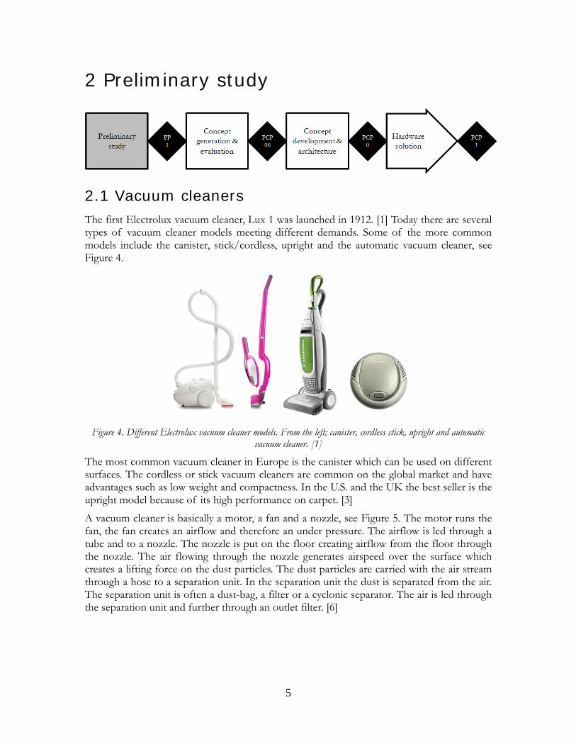
2.1 Vacuum cleaners The first Electrolux vacuum cleaner, Lux 1 was launched in 1912. [1] Today there are several types of vacuum cleaner models meeting different demands. Some of the more common models include the canister, stick/cordless, upright and the automatic vacuum cleaner, see Figure 4.
Figure 4. Different Electrolux vacuum cleaner models. From the left; canister, cordless stick, upright and automatic
vacuum cleaner. [1]
The most common vacuum cleaner in Europe is the canister which can be used on different surfaces. The cordless or stick vacuum cleaners are common on the global market and have advantages such as low weight and compactness. In the U.S. and the UK the best seller is the upright model because of its high performance on carpet. [3]
A vacuum cleaner is basically a motor, a fan and a nozzle, see Figure 5. The motor runs the fan, the fan creates an airflow and therefore an under pressure. The airflow is led through a tube and to a nozzle. The nozzle is put on the floor creating airflow from the floor through the nozzle. The air flowing through the nozzle generates airspeed over the surface which creates a lifting force on the dust particles. The dust particles are carried with the air stream through a hose to a separation unit. In the separation unit the dust is separated from the air. The separation unit is often a dust-bag, a filter or a cyclonic separator. The air is led through the separation unit and further through an outlet filter. [6]
5
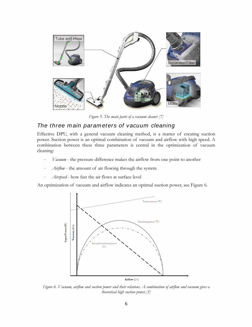
Figure 5. The main parts of a vacuum cleaner [7]
The three main parameters of vacuum cleaning Effective DPU, with a general vacuum cleaning method, is a matter of creating suction power. Suction power is an optimal combination of vacuum and airflow with high speed. A combination between these three parameters is central in the optimization of vacuum cleaning:
⋅ Vacuum - the pressure difference makes the airflow from one point to another
⋅ Airflow - the amount of air flowing through the system
⋅ Airspeed - how fast the air flows at surface level
An optimization of vacuum and airflow indicates an optimal suction power, see Figure 6.
Figure 6. Vacuum, airflow and suction power and their relations. A combination of airflow and vacuum gives a
theoretical high suction power.[3]
6
High airspeed results in increased DPU but creates higher noise when flowing through the system. Increased pressure difference, i.e. vacuum, increases the airspeed but it also increases the force needed to move the nozzle, motion resistance, over the floor or carpet. A larger pressure difference also relates to losses in the system; increased pressure difference leads to increased losses. [3]
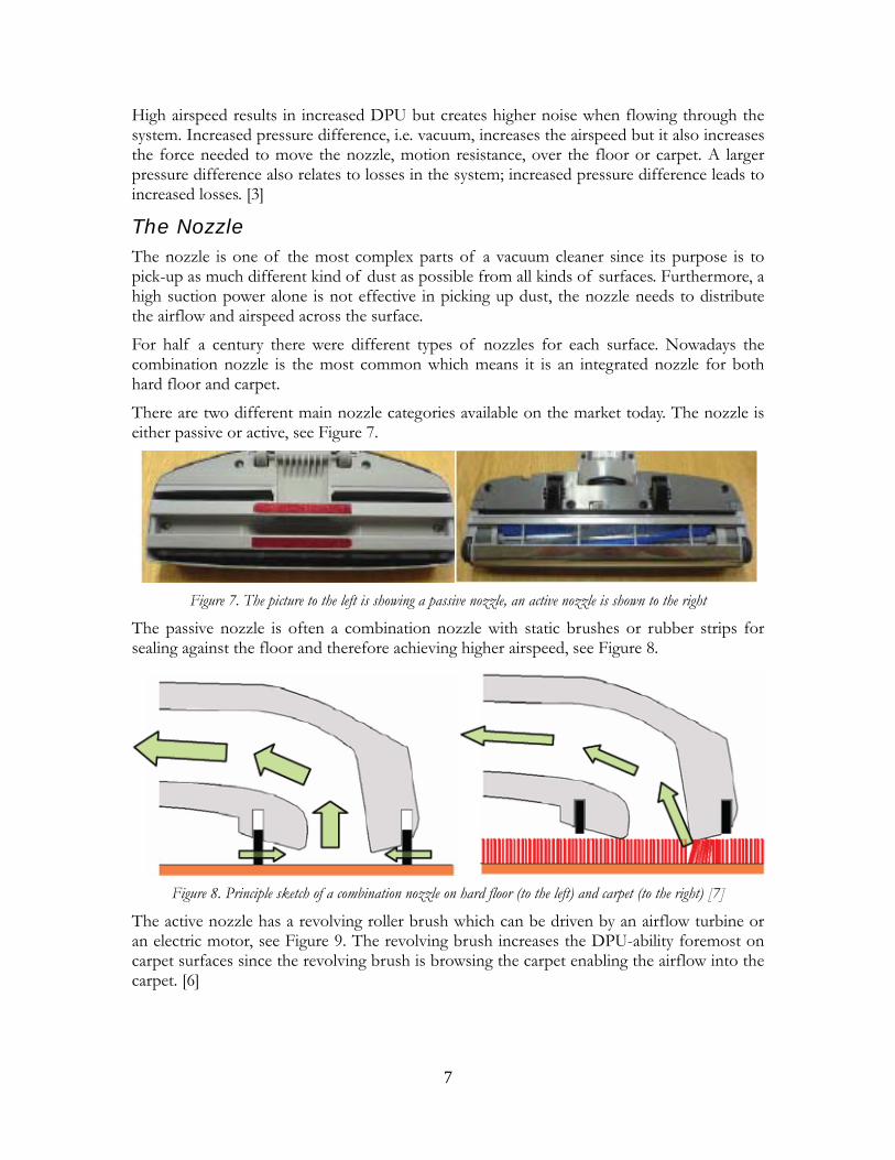
The Nozzle The nozzle is one of the most complex parts of a vacuum cleaner since its purpose is to pick-up as much different kind of dust as possible from all kinds of surfaces. Furthermore, a high suction power alone is not effective in picking up dust, the nozzle needs to distribute the airflow and airspeed across the surface.
For half a century there were different types of nozzles for each surface. Nowadays the combination nozzle is the most common which means it is an integrated nozzle for both hard floor and carpet.
There are two different main nozzle categories available on the market today. The nozzle is either passive or active, see Figure 7.
Figure 7. The picture to the left is showing a passive nozzle, an active nozzle is shown to the right
The passive nozzle is often a combination nozzle with static brushes or rubber strips for sealing against the floor and therefore achieving higher airspeed, see Figure 8.
Figure 8. Principle sketch of a combination nozzle on hard floor (to the left) and carpet (to the right) [7]
The active nozzle has a revolving roller brush which can be driven by an airflow turbine or an electric motor, see Figure 9. The revolving brush increases the DPU-ability foremost on carpet surfaces since the revolving brush is browsing the carpet enabling the airflow into the carpet. [6]
7
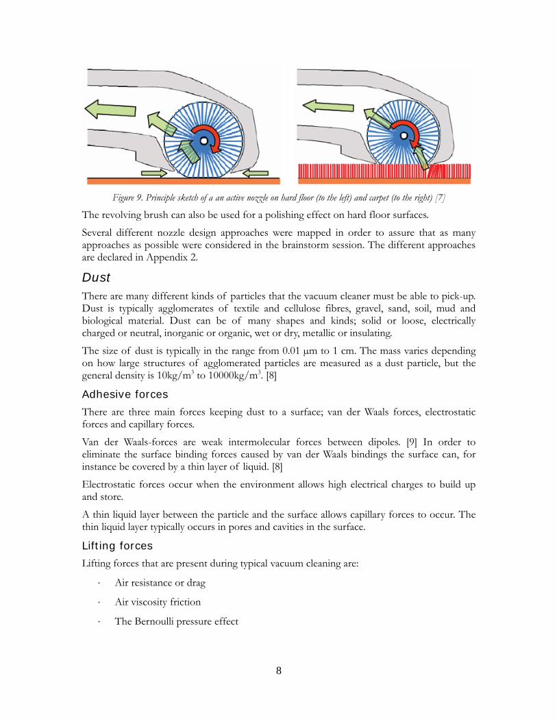
Figure 9. Principle sketch of a an active nozzle on hard floor (to the left) and carpet (to the right) [7]
The revolving brush can also be used for a polishing effect on hard floor surfaces.
Several different nozzle design approaches were mapped in order to assure that as many approaches as possible were considered in the brainstorm session. The different approaches are declared in Appendix 2.
Dust There are many different kinds of particles that the vacuum cleaner must be able to pick-up. Dust is typically agglomerates of textile and cellulose fibres, gravel, sand, soil, mud and biological material. Dust can be of many shapes and kinds; solid or loose, electrically charged or neutral, inorganic or organic, wet or dry, metallic or insulating.
The size of dust is typically in the range from 0.01 µm to 1 cm. The mass varies depending on how large structures of agglomerated particles are measured as a dust particle, but the general density is 10kg/m3 to 10000kg/m3. [8]
Adhesive forces There are three main forces keeping dust to a surface; van der Waals forces, electrostatic forces and capillary forces.
Van der Waals-forces are weak intermolecular forces between dipoles. [9] In order to eliminate the surface binding forces caused by van der Waals bindings the surface can, for instance be covered by a thin layer of liquid. [8]
Electrostatic forces occur when the environment allows high electrical charges to build up and store.
A thin liquid layer between the particle and the surface allows capillary forces to occur. The thin liquid layer typically occurs in pores and cavities in the surface.
Lifting forces Lifting forces that are present during typical vacuum cleaning are:
⋅ Air resistance or drag
⋅ Air viscosity friction
⋅ The Bernoulli pressure effect
8
In order to lift a dust particle the sum of all above given forces must be larger than the adhesive forces keeping it down. [8]
There are other known methods for removing the adhesive forces on the dust particle such as revolving or static brushes [8]. Brushes are attached to the nozzle to bring a force to the dust particles, the force from a brush on a dust particle can be described by Equation 1:
33lEIF δ= (1)
Where l is the length of the brush bristle, δ is the distance that the bristle is displaced, E is the brush bristles elastic module and I is the cross-section inertia factor.
Other, non-conventional methods, for overcoming the adhesive forces can be: sound waves, wet wiping, liquid and vapour dispersion and electric charging. [8]
Power losses Normally a vacuum cleaner has an input power of 1600-2200W and the suction power is approximately 200-500W. [3] That concludes to an average loss of 1250W via the motor, fan, tube and nozzle.
A key to improving the energy efficiency in a vacuum cleaner system is the knowledge of the pressure variations from one part of the system to another. The purpose with this analysis is to give the reader an understanding of where the input power is used.
The power loss, P, in each part of the vacuum cleaner is directly related to the pressure drop and the airflow, Q, as stated in Equation 2: 12 ppp −=Δ
pQP Δ= (2)
Generally the flow is the same throughout the vacuum cleaner. It is the pressure that is varied. More input power generates higher airflow and therefore gives more suction power, but the relation is not linear. The amount of suction power gained with every amount of input power added decreases due to losses caused by increased airflow. The pressure drop ( ) increases with the flow to the second power [10], Equation 3: 12 ppp −=Δ
2~ QpΔ (3)
The motor and the fan The largest power loss is in the motor and the fan. The fan is working as a vacuum pump and is therefore using a lot of power. The fan is the only power loss that is requested. The electrical motor, running the fan, contains internal power losses such as resistive losses in the coil windings, mechanical losses and magnetic hysteresis.
The hose, bent end and tube If the pressure drop between the nozzle and the surface is not calculated, since the power is used mainly for accelerating the air and therefore removing dust which in this case is not considered as a loss, the largest pressure drop is in the hose, bent end and tube section (HBT-section). Equation 4 explains the relation between the pressure drop, p, and the tube diameter, d: [10]
9
5~ −Δ dp (4)
The pressure drop and therefore the power loss in the HBT-section can be reduced by enlarging the tube diameter, even the inner roughness of the tube or decreasing the length.
The nozzle A specific energy analysis for the vacuum cleaner nozzle is hard to establish, mainly because a loss in the nozzle is hard to define. A loss can be described as for example; not reaching a dust particle or as a fluid mechanical loss when air is pressed through a narrow passage and accelerated. As for all other parts of the vacuum cleaner narrow passages and sudden changes in geometry relates to losses. It is hard to overlook that the nozzle geometry requires some sudden changes and narrow passages in order to accelerate the inlet air to required speed for lifting a dust particle.
Furthermore, a nozzle can be designed in indefinite variations and is used on a wide range of different surfaces. Losses are in a very high degree related to which kind of surface the nozzle is used on. On a carpet the airflow passage is often narrowed, compared to hard floor usage, the amount of air flowing through the system is decreased. A decreased airflow itself decreases the overall losses in the system.
An active nozzle using a motor brush is also a source of nozzle power loss. The design of the brush is directly related to the energy consumption. The basic rule is that - the more resistance revolving the brush due to carpet contact - the more current is required and therefore more power is required to keep the brush revolving.
However, in the canister model the revolving brush requires significantly less energy than the entire system (typically 50W compared to 2000W), and is therefore not a major source of power loss. The upright models have a more powerful revolving brush. The roller brush is generally larger, the tufts are stiffer and the roller brush requires more power (150-350W) compared to the revolving brushes used in the canister model nozzles. [3]
The separation and filters Generally the more filled a dust bag is the greater pressure drop. Separation can also be done by using cyclonic technology, the power loss in a cyclonic separation depends on the layout and design of the cyclone but generally the cyclonic separation has a more constant power loss. A dust bag has an increasing power loss depending on the amount of dust picked up and stored in the dust bag. The constant power loss of a cyclonic separation system is generally comparable to a dust bag that is filled to 50%. [6]
In common vacuum cleaners there is also an outlet filter, filtrating a very high fraction of the particles, making the air coming out of the vacuum cleaner, more clean than the surroundings. The pressure change over a standard HEPA-filter is approximately 1-3kPa. [8]
Dust pick-up Establishing the performance, i.e. DPU-ability, of a vacuum cleaner is done in a standard test (IEC60312, ed.4, clause 2.3) that is equal for all major actors. The DPU-test is also used by test institutes that rates different vacuum cleaner systems on DPU-ability on different surfaces.
10
The standard test is done on three different surfaces; hard floor, hard floor with crevice and carpet. The DPU-ability is measured for different airflows. The amount of dust used depends on the width of the nozzle. [11]
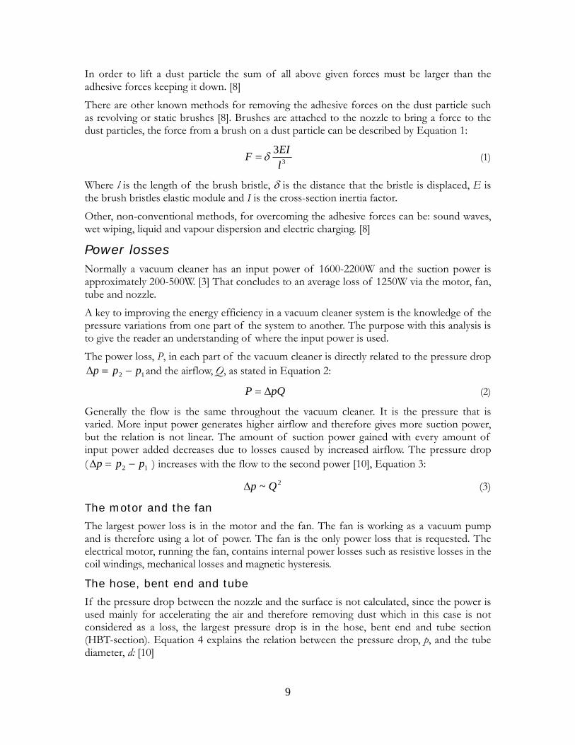
The carpet, hard floor and crevice test is done in an automatic vacuum cleaner rig where the vacuum cleaner has a motion speed of 0.5m/s, see Figure 10. Traditionally the vacuum cleaner is moved back and forth across the surface five times, i.e. five double strokes (5DS). The DPU-ability can also be measured for single front strokes (FS) or backward strokes (BS) and also for a single double stroke (1DS). This procedure becomes more relevant with energy labelling, since the time is a major factor in energy consumption.
Figure 10. The DPU-test rig [7]
The surface is vacuumed, the amount of dust in the dust bag is measured after each test and the DPU-ability is calculated as the amount of dust that is picked up from the surface.
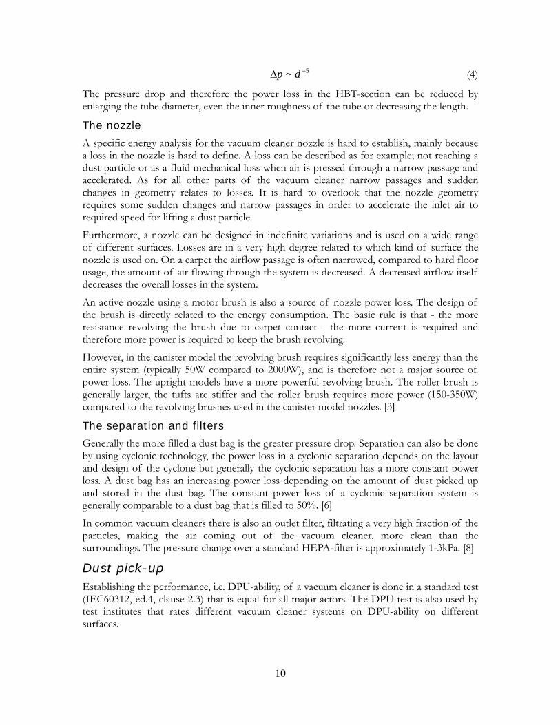
TABLE 1 shows DPU-ability for the two top ranked vacuum cleaner nozzles by Electrolux. [11] The energy efficient factor, EEF is a factor measuring how energy efficient the DPU is. Further information on EEF is available in chapter 2.3.
TABLE 1. DPU-ability for top performing vacuum cleaner nozzles
Nozzle
Strok
eTota
l inpu
t pow
er (W
)
Airflow
(l/s)
DPU carpe
t (%)
DPU hard
floor
(%)
DPU crevi
ce (%
)
EEF(10-3 )
(%m2 /W
s)
Sumo Passive 5DS 1600 41 80 99,3 93 0,76Sumo Active 5DS 2000 43 85 99,5 98 0,652G Passive 5DS 2000 43 82 99,8 104 0,622G Active 5DS 2000 43 87 99,5 100 0,66
11
Carpet wear Carpet wear needs to be considered especially with active nozzles. Carpet wear includes removal of carpet fibres and other changes in the appearance of the carpet after vacuum cleaning. The major factors of carpet wear are:
⋅ Rotational speed of the roller brush
⋅ Bristle material
⋅ Tuft size and stiffness
⋅ Length of time in the carpet
⋅ Resultant force applied by the nozzle
⋅ Airflow
⋅ The presence and quality of a carpet pad and the sub floor material
⋅ Engagement level
To minimize the carpet wear, rotational speed and length of time in carpet should be as low as possible. A typical bristle material for minimizing the risk for carpet wear is nylon since it has low friction against carpet material. If the airflow is not high enough, dust particles get stuck in the revolving brush chamber and therefore increases the carpet wear. [12]
Carpet burn is a problem that mostly exists in the U.S. and the UK where stiff revolving brushes are common. The damage is a result of the friction between the roller brush and the carpet. The heat generated by the friction is causing the carpet bristles to melt together. [12]
Today there are no standard tests for measuring the carpet wear. There are proposals for an upcoming standard for carpet wear tests, which in summary is to keep the nozzle in the same position for two minutes and subsequently visually identifying the carpet wear and changes in surface appearance.
Motion resistance Moving a nozzle across a surface requires a certain amount of force. This force is called motion resistance. The amount of force depends on the friction between the nozzle and surface, which surface (increased friction on carpet), under-pressure and airflow.
A vacuum cleaner with low airflow generally has lower motion resistance. There is a high variation between different nozzles but a maximum motion resistance of 50N is considered to be user friendly. [3]
2.2 Energy labelling The European Commission has a proposal for energy labelling of vacuum cleaners that is estimated to be applied in 2010/2011. The Council and the European Parliament has a Commission proposal for a directive on establishing a framework for setting Eco-design requirements for all energy using products in the residential, tertiary and industrial sector.
12
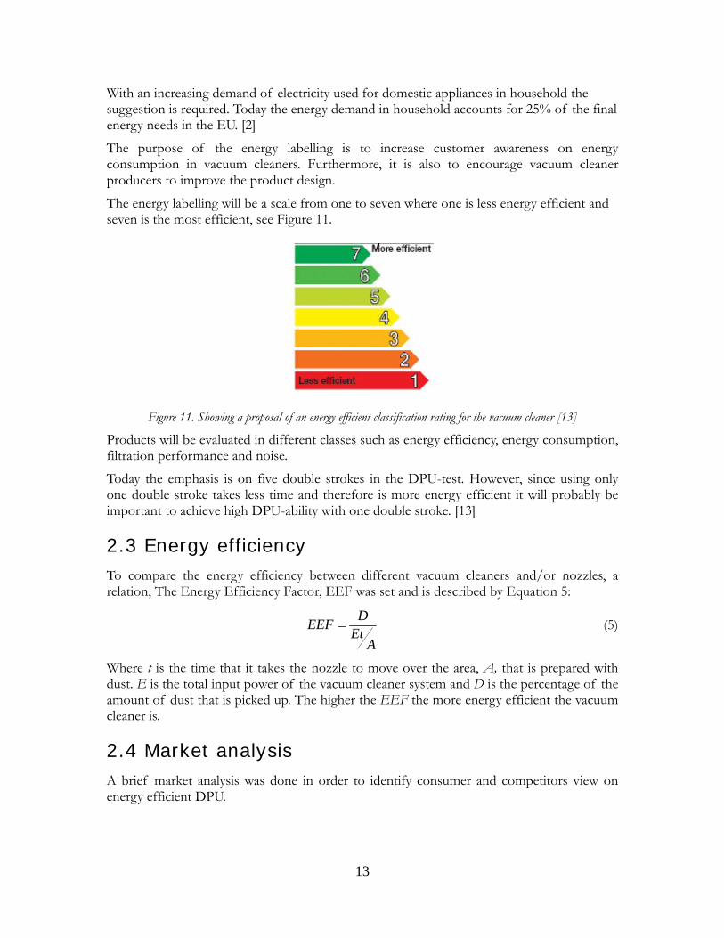
With an increasing demand of electricity used for domestic appliances in household the suggestion is required. Today the energy demand in household accounts for 25% of the final energy needs in the EU. [2]
The purpose of the energy labelling is to increase customer awareness on energy consumption in vacuum cleaners. Furthermore, it is also to encourage vacuum cleaner producers to improve the product design.
The energy labelling will be a scale from one to seven where one is less energy efficient and seven is the most efficient, see Figure 11.
Figure 11. Showing a proposal of an energy efficient classification rating for the vacuum cleaner [13]
Products will be evaluated in different classes such as energy efficiency, energy consumption, filtration performance and noise.
Today the emphasis is on five double strokes in the DPU-test. However, since using only one double stroke takes less time and therefore is more energy efficient it will probably be important to achieve high DPU-ability with one double stroke. [13]
2.3 Energy efficiency To compare the energy efficiency between different vacuum cleaners and/or nozzles, a relation, The Energy Efficiency Factor, EEF was set and is described by Equation 5:
DEEF EtA
= (5)
Where t is the time that it takes the nozzle to move over the area, A, that is prepared with dust. E is the total input power of the vacuum cleaner system and D is the percentage of the amount of dust that is picked up. The higher the EEF the more energy efficient the vacuum cleaner is.
2.4 Market analysis A brief market analysis was done in order to identify consumer and competitors view on energy efficient DPU.
13
Consumers Consumer analysis that was made by Consumer Insight and Marketing department at Electrolux showed that the major part of vacuum cleaner consumer believed that an input wattage increasing at least 1200W was needed for good cleaning performance.
Competitors Electrolux is one of major actors on the vacuum cleaner market and has a market share of 14% of the global market. Competitors include Dyson, Miele, Hoover, Wesselwerk, Bosch-Siemens, LG, Bissel, Royal, Samsung and Haier. [1] In the Asian market brands as Toshiba, Sharp, Seizo, Mitsubishi, Hitachi and Matsushita/Panasonic are major competitors. [6]
The competitor analysis indicated that today, energy efficiency is not a main marketing approach for any of the competitors.
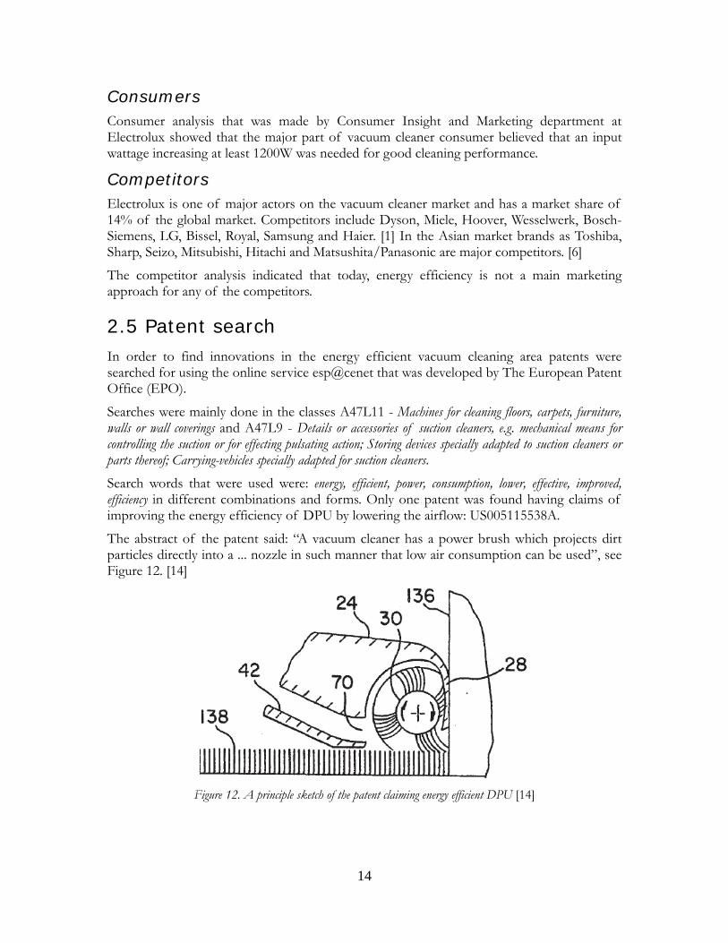
2.5 Patent search In order to find innovations in the energy efficient vacuum cleaning area patents were searched for using the online service esp@cenet that was developed by The European Patent Office (EPO).
Searches were mainly done in the classes A47L11 - Machines for cleaning floors, carpets, furniture, walls or wall coverings and A47L9 - Details or accessories of suction cleaners, e.g. mechanical means for controlling the suction or for effecting pulsating action; Storing devices specially adapted to suction cleaners or parts thereof; Carrying-vehicles specially adapted for suction cleaners. Search words that were used were: energy, efficient, power, consumption, lower, effective, improved, efficiency in different combinations and forms. Only one patent was found having claims of improving the energy efficiency of DPU by lowering the airflow: US005115538A.
The abstract of the patent said: “A vacuum cleaner has a power brush which projects dirt particles directly into a ... nozzle in such manner that low air consumption can be used”, see Figure 12. [14]
Figure 12. A principle sketch of the patent claiming energy efficient DPU [14]
14
2.6 Requirement specification A requirement specification was established in order to map the demands on the outcome of this master thesis. The requirement specification had few requirements, relating mainly to the energy efficiency demands, since the outcome of the master thesis was a prototype made for investigation purposes only. More specific demands are required in a later phase of the Product Creation Process.
15

16
3 Concept generation & evaluation
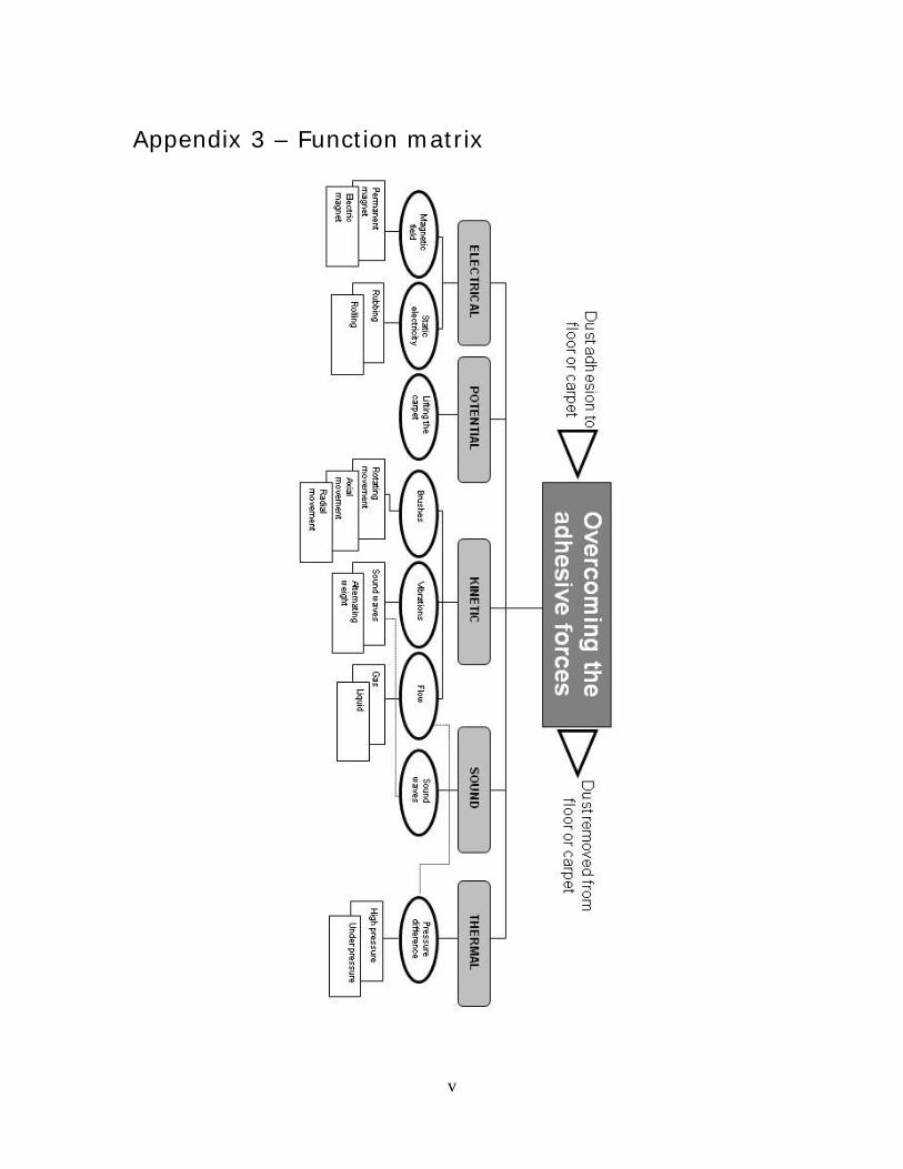
3.1 Concept generation Subsequent to the preliminary study the concept generation phase was initiated by establishing a function matrix where different approaches on overcoming the adhesive forces were made, see Appendix 3.
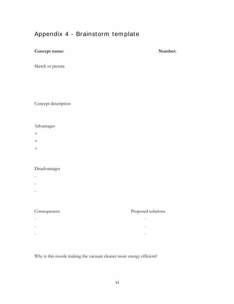
Brainstorm session After establishing the function matrix a brainstorm-session was held. Ideas were sketched, discussed and archived by the use of a brainstorm template, see Appendix 4. In the template the ideas were individually described by a descriptive sketch and a written function description.
Advantages and disadvantages that were discussed during the session were also written on the template. Eventually, ideas on how to solve the disadvantages came up and were also discussed and written on the template.
The main focus of the brainstorm session was how to improve the nozzle in order to achieve energy efficient DPU. Every idea during the brainstorm session was evaluated in terms of energy efficiency; “How is this concept making the DPU more energy efficient?”
Electrolux creativity workshop In order to cover a large amount of possible solutions and to get a second opinion on already existing ideas, a creativity workshop was arranged for the employees at Electrolux Floor Care and Small Appliances, Global Primary Development and Innovation.
The first part of the workshop included a creativity session that was inspired by a more familiar brain writing method called As Easy As 6-3-5. [15]
A blank paper was handed out. Every person sketches an idea for a defined problem during five minutes. In this case the problem was stated as: “A vacuum cleaner nozzle that enables energy efficient DPU”. No text or words explaining the idea on the paper was allowed. When the five minutes was up the sketch was passed to the next person. During the next three minutes the person that received the new sketch tried to understand and improve the idea. When the three minutes were up the original sketcher described his or hers idea and the improver described how he or she perceived the sketch and how it was improved. The different approaches were discussed and analyzed by the workshop-members.
17
3.2 Concept evaluation
Two methods were used to evaluate which concepts were most promising.
1. Consulting experts - Interviews and discussions with experts on vacuum cleaner nozzles at Electrolux.
2. Multivoting - A workshop with employees of Electrolux Floor Care and Small Appliances, Global Primary Development and Innovation department was held. The participants had three votes of a specific value; “Good”, “Better” and “Best”.
More than 40 concepts were evaluated by the use of the methods above. Concepts that were chosen for further development were:
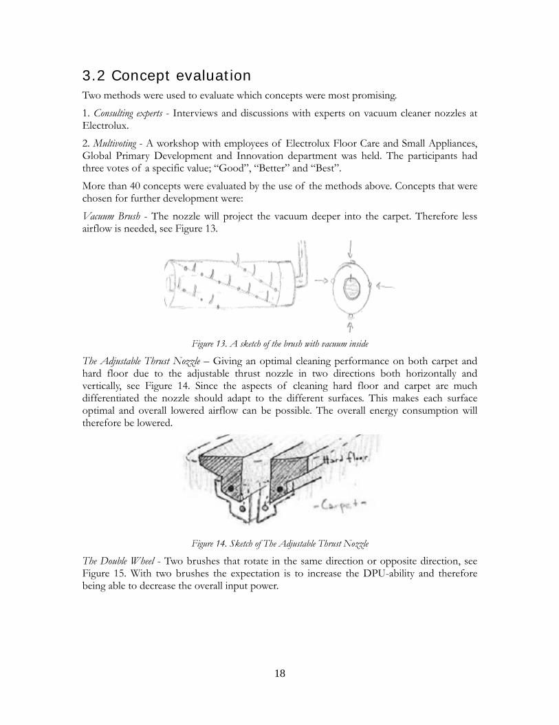
Vacuum Brush - The nozzle will project the vacuum deeper into the carpet. Therefore less airflow is needed, see Figure 13.
Figure 13. A sketch of the brush with vacuum inside
The Adjustable Thrust Nozzle – Giving an optimal cleaning performance on both carpet and hard floor due to the adjustable thrust nozzle in two directions both horizontally and vertically, see Figure 14. Since the aspects of cleaning hard floor and carpet are much differentiated the nozzle should adapt to the different surfaces. This makes each surface optimal and overall lowered airflow can be possible. The overall energy consumption will therefore be lowered.
Figure 14. Sketch of The Adjustable Thrust Nozzle
The Double Wheel - Two brushes that rotate in the same direction or opposite direction, see Figure 15. With two brushes the expectation is to increase the DPU-ability and therefore being able to decrease the overall input power.
18
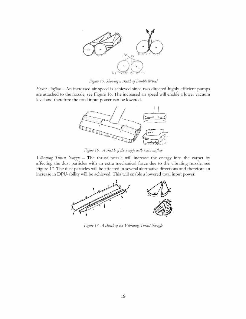
Figure 15. Showing a sketch of Double Wheel
Extra Airflow – An increased air speed is achieved since two directed highly efficient pumps are attached to the nozzle, see Figure 16. The increased air speed will enable a lower vacuum level and therefore the total input power can be lowered.
Figure 16. A sketch of the nozzle with extra airflow
Vibrating Thrust Nozzle – The thrust nozzle will increase the energy into the carpet by affecting the dust particles with an extra mechanical force due to the vibrating nozzle, see Figure 17. The dust particles will be affected in several alternative directions and therefore an increase in DPU-ability will be achieved. This will enable a lowered total input power.
Figure 17. A sketch of the Vibrating Thrust Nozzle
19

20
4 Concept development & architecture
On the steering-group meeting, at the check point PCP00, the decision was made to continue development and investigation of all the concepts left after the concept evaluation. None of the concept could be left out until they are thoroughly tested in standard performance tests.
The master thesis will from this checkpoint focus on establishing a test and development plan for all of the concepts. The time consuming nature of the tests will divide this master thesis in two parts; one part consisting of preliminary study and a development plan (this report) as well as a second part that will be available at the examiner of this master thesis.
Test and development plan All of the concepts need to be tested in standard performance test. Therefore a physical prototype needs to be built of every concept that fits in the DPU-test rig.
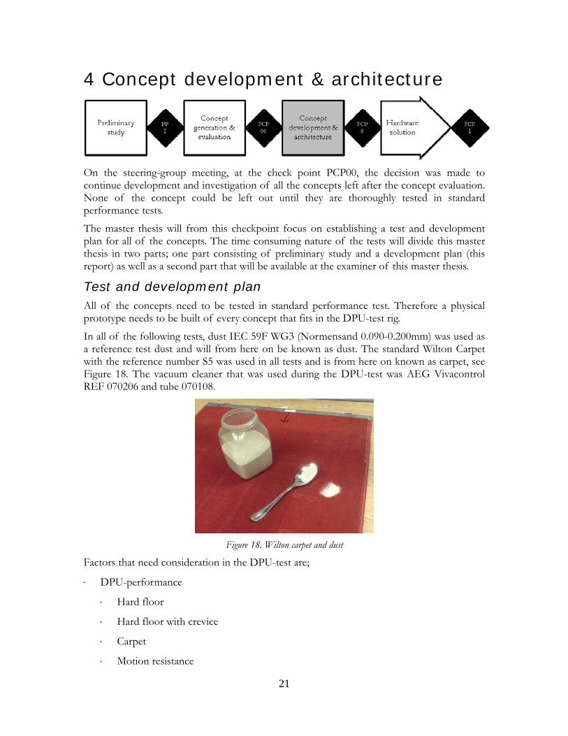
In all of the following tests, dust IEC 59F WG3 (Normensand 0.090-0.200mm) was used as a reference test dust and will from here on be known as dust. The standard Wilton Carpet with the reference number S5 was used in all tests and is from here on known as carpet, see Figure 18. The vacuum cleaner that was used during the DPU-test was AEG Vivacontrol REF 070206 and tube 070108.
Figure 18. Wilton carpet and dust
Factors that need consideration in the DPU-test are;
⋅ DPU-performance
⋅ Hard floor
⋅ Hard floor with crevice
⋅ Carpet
⋅ Motion resistance
21
⋅ Airflow
⋅ Low (24.4l/s)
⋅ Medium (32l/s)
⋅ High (38l/s)
In addition to the standard tests, there are other tests that the concepts need to be evaluated on:
Surface wear – Establish the impact of the different approaches
EEF – Establish the energy efficiency of every concept in standard DPU-tests
However, there are several individual parameters that need to be investigated.
Vacuum Brush Distribution of vacuum - Find out the optimal way of distributing the airflow from the source to the surface
Pulsating – Investigate the impact of pulsating vacuum level
Brush – Placement of the brush and the effect of different engagement levels
Motor – The placement of the motor might have effect on the DPU-ability due to weight distribution
Carpet wear – Establish the level of damage to the surface
Adjustable Thrust Nozzle Motor – The placement of the motor might have effect on the DPU-ability due to weight distribution
Horizontal and vertical adjusting level – Establish the most optimal adjustment level
Mechanism – Establish the function of the mechanism
Double Wheel Rotational direction – Establish the most optimal rotational direction of the brushes
Brush – Investigate different material and layout
Thrust nozzle – Find the most optimal way to improve and sustain the vacuum level inside the nozzle
Extra Airflow Positioning pumps – Investigate the effect of the positioning of the pumps
Direction of the airflow – Direct the airflow in different ways to find the most optimal direction
Amount of air – How much air and air pressure is needed in order to overcome the already high vacuum level in the nozzle
Air outlet positioning – Investigate how the air outlet position should be placed inside the nozzle
22
Vacuum level – Establish the vacuum level that is fitted for the extra airflow that is added to the nozzle
Vibrating Thrust Nozzle Mechanism – Establish the function of the mechanism
Pulsating – Investigate the impact of pulsating vibrations
Motor – The placement of the motor might affect the DPU-ability due to weight distribution
23

24
5 Results
The tests that were done during the concept development and architecture phase are, during the writing of this report, still to be finished and enclosed. The results, analyze, conclusions and discussion of the test results, the second act, are available at the examiner of this master thesis.
25

26
6 Discussion
6.1 Preliminary study It was clear during the market study that the majority of the vacuum cleaner consumers are not educated in the facts about the energy consumption of vacuum cleaners.
The fact that a high input power is not equal to high DPU-ability is very important both regarding customer needs and the environment. Rather than comparing the input power of different vacuum cleaners the DPU-ability should be compared. Comparing the input power of vacuum cleaners, when deciding on which have the best performance, can be compared to buying a car based solely on which car has the highest petrol consumption.
During the preliminary study it was identified that there are several other modifications that can be done to a vacuum cleaner in order to decrease the energy consumption, such as compressor or filter improvements. However, these measures were not considered in this master thesis but should, when further developing a complete energy efficient vacuum system, be considered.
6.2 Concept generation & evaluation The combination of having a brainstorm session before and after the preliminary study gave a wide range of alternative ideas and concepts available for the upcoming evaluation and development. The initial part gave ideas that focused on alternative methods for DPU and the second part gave ideas that were more specific and it was clear that the problem had been identified and understood.
Finishing the brainstorm sessions and the concept generation phase with a workshop was very successful. During the workshop valuable second opinions, improvements and new ideas were added to already existing concepts.
To evaluate concepts in a fair and non intuitive way it is important to verify if the concepts fulfil the requirement specification. Verification could have been done by, for example, scoring matrixes, prototyping, tests or mathematical models. The nature of this particular problem is that it is complex due to a lot of parameters affecting the result and it is hard to verify how well a concept fulfils the requirement specification with, for instance, a mathematical simplification.
The project had no specific limitations, requirements or demands considering parameters such as material, cost, size or weight. However, the most important demand on this product is the achievement of energy efficient DPU. That demand is hard to verify without an actual prototype that is designed for the standard DPU-tests. Prototyping every was extremely time consuming and therefore is this master thesis divided into two separate reports.
6.3 Concept development & architecture The energy efficiency factor, EEF gives a comparable value for different vacuum cleaners and their energy efficiency. The energy efficiency increases drastically when dust is picked up
27
using only one stroke in either direction. When vacuuming the same area several times it gets harder and harder to increase the DPU percentage. Therefore, it will be important to achieve good DPU already after one double stroke in order to achieve high ranking in the energy labelling.
28
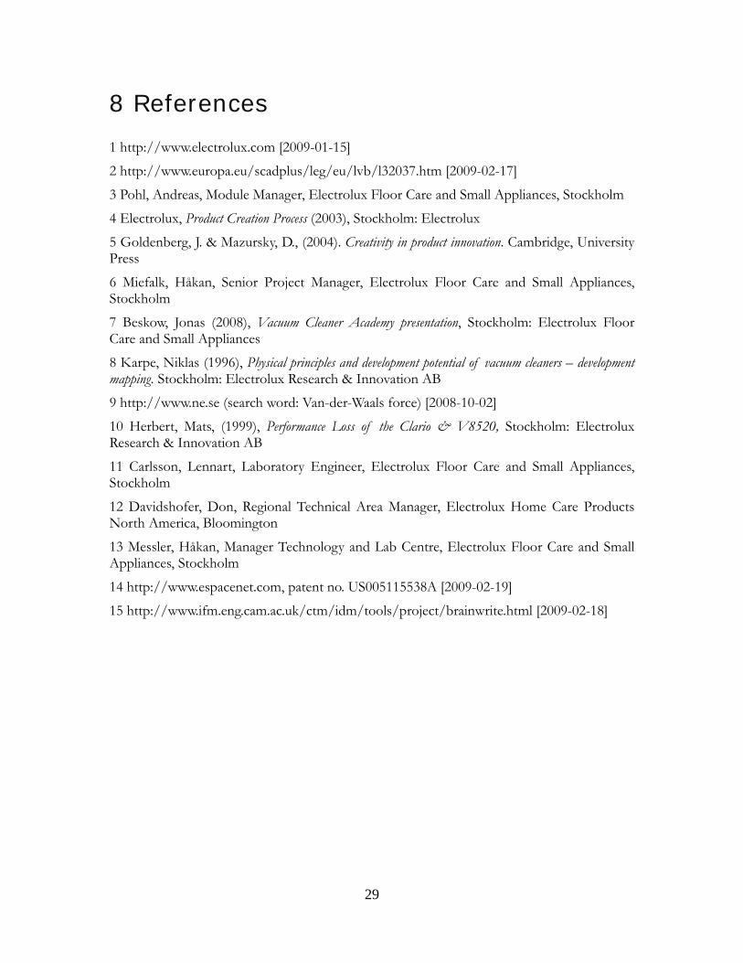
8 References
1 http://www.electrolux.com [2009-01-15]
2 http://www.europa.eu/scadplus/leg/eu/lvb/l32037.htm [2009-02-17]
3 Pohl, Andreas, Module Manager, Electrolux Floor Care and Small Appliances, Stockholm
4 Electrolux, Product Creation Process (2003), Stockholm: Electrolux
5 Goldenberg, J. & Mazursky, D., (2004). Creativity in product innovation. Cambridge, University Press
6 Miefalk, Håkan, Senior Project Manager, Electrolux Floor Care and Small Appliances, Stockholm
7 Beskow, Jonas (2008), Vacuum Cleaner Academy presentation, Stockholm: Electrolux Floor Care and Small Appliances
8 Karpe, Niklas (1996), Physical principles and development potential of vacuum cleaners – development mapping. Stockholm: Electrolux Research & Innovation AB
9 http://www.ne.se (search word: Van-der-Waals force) [2008-10-02]
10 Herbert, Mats, (1999), Performance Loss of the Clario & V8520, Stockholm: Electrolux Research & Innovation AB
11 Carlsson, Lennart, Laboratory Engineer, Electrolux Floor Care and Small Appliances, Stockholm
12 Davidshofer, Don, Regional Technical Area Manager, Electrolux Home Care Products North America, Bloomington
13 Messler, Håkan, Manager Technology and Lab Centre, Electrolux Floor Care and Small Appliances, Stockholm
14 http://www.espacenet.com, patent no. US005115538A [2009-02-19]
15 http://www.ifm.eng.cam.ac.uk/ctm/idm/tools/project/brainwrite.html [2009-02-18]
29

30
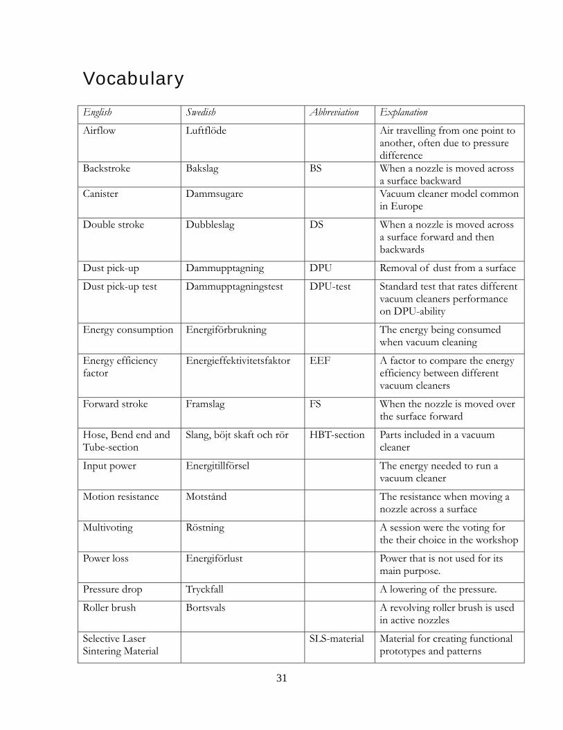
Vocabulary
English Swedish Abbreviation Explanation
Airflow Luftflöde Air travelling from one point to another, often due to pressure difference
Backstroke
Bakslag BS When a nozzle is moved across a surface backward
Canister Dammsugare Vacuum cleaner model common in Europe
Double stroke Dubbleslag DS When a nozzle is moved across a surface forward and then backwards
Dust pick-up Dammupptagning DPU Removal of dust from a surface
Dust pick-up test Dammupptagningstest DPU-test Standard test that rates different vacuum cleaners performance on DPU-ability
Energy consumption Energiförbrukning The energy being consumed when vacuum cleaning
Energy efficiency factor
Energieffektivitetsfaktor EEF A factor to compare the energy efficiency between different vacuum cleaners
Forward stroke Framslag FS When the nozzle is moved over the surface forward
Hose, Bend end and Tube-section
Slang, böjt skaft och rör HBT-section Parts included in a vacuum cleaner
Input power Energitillförsel The energy needed to run a vacuum cleaner
Motion resistance Motstånd The resistance when moving a nozzle across a surface
Multivoting Röstning A session were the voting for the their choice in the workshop
Power loss Energiförlust Power that is not used for its main purpose.
Pressure drop Tryckfall A lowering of the pressure.
Roller brush Bortsvals A revolving roller brush is used in active nozzles
Selective Laser Sintering Material
SLS-material Material for creating functional prototypes and patterns
31
32
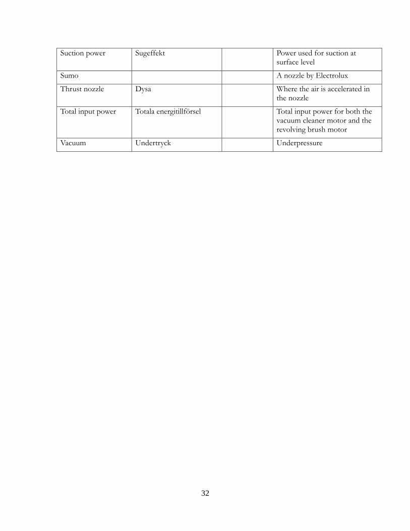
Suction power Sugeffekt Power used for suction at surface level
Sumo A nozzle by Electrolux
Thrust nozzle Dysa Where the air is accelerated in the nozzle
Total input power Totala energitillförsel Total input power for both the vacuum cleaner motor and the revolving brush motor
Vacuum Undertryck Underpressure

Appendix
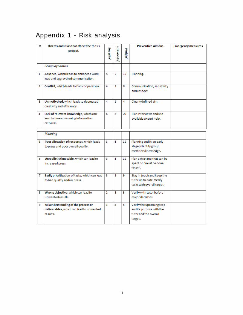
Appendix 1 - Risk analysis
ii
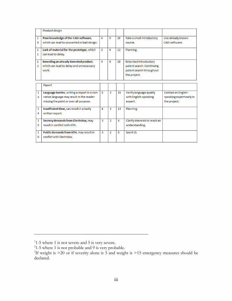
__________________________________________________ 11-5 where 1 is not severe and 5 is very severe. 21-5 where 1 is not probable and 9 is very probable. 3If weight is >20 or if severity alone is 5 and weight is >15 emergency measures should be declared.
iii
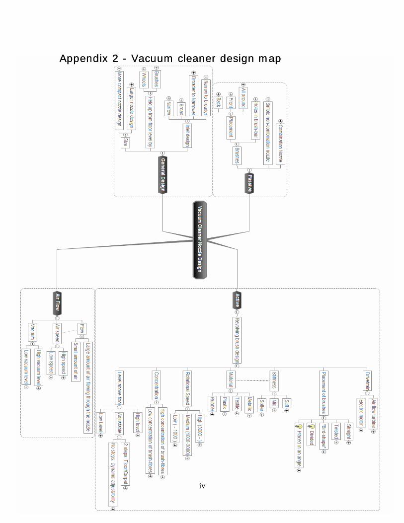
Appendix 2 - Vacuum cleaner design map Appendix 2 - Vacuum cleaner design map
iv
Appendix 3 – Function matrix
v
vi
Appendix 4 - Brainstorm template
Concept name: Number:
Sketch or picture
Concept description
Advantages
+
+
+
Disadvantages
-
-
-
Consequences Proposed solutions
- -
- -
- -
Why is this nozzle making the vacuum cleaner more energy efficient?