Embed Size (px)
Citation preview

Development of a Two-Joint Robotic Fishfor Real-World Exploration
• • • • • • • • • • • • • • • • • • • • • • • • • • • • • • • • • • • •
Jianhong Liang, Tianmiao Wang, and Li WenRobotics Institute, Beihang University, 37 Xueyuan Road, Beijing 100191, People’s Republic of Chinae-mail: dommy [email protected]
Received 16 February 2010; accepted 18 July 2010
Research on biomimetic robotic fish has been undertaken for more than a decade. Various robotic fish proto-types have been developed around the world. Although considerable research efforts have been devoted tounderstanding the underlying mechanism of fish swimming and construction of fish-like swimming machines,robotic fish have largely remained laboratory curiosities. This paper presents a robotic fish that is designedfor application in real-world scenarios. The robotic fish adopts a rigid torpedo-shaped body for the housingof power, electronics, and payload. A compact parallel four-bar mechanism is designed for propulsion andmaneuvering. Based on the kinematic analysis of the tail mechanism, the motion control algorithm of jointsis presented. The swimming performance of the robotic fish is investigated experimentally. The swimmingspeed of the robotic fish can reach 1.36 m/s. The turning radius is 1.75 m. Powered by the onboard battery, therobotic fish can operate for up to 20 h. Moreover, the advantages of the biomimetic propulsion approach areshown by comparing the power efficiency and turning performance of the robotic fish with that of a screw-propelled underwater vehicle. The application of the robotic fish in a real-world probe experiment is alsopresented. C© 2010 Wiley Periodicals, Inc.
1. INTRODUCTION
The study of swimming mechanisms of fish and the devel-opment of bionic engineering have shown that bioroboticunderwater vehicles have potential advantages in terms ofmaneuverability, environmental suitability, and low noise.The fin-powered Transphibian robot developed by iRobotcan be used as an autonomous unmanned undersea vehicle(UUV) and bottom crawler, and it shows potential appli-cation in mine detection, harbor defense, surveillance, andreconnaissance (iRobot Maritime Robots—Transphibian,2010). Hu, Liu, Duks, and Francis (2006) are trying to de-velop a carp-like robotic fish to find the source of poten-tially hazardous pollutants in the water. Mbemmo, Chen,Shatara, and Tan (2008) built a robotic fish propelled withan ionic polymer metal composite (IPMC) actuator. Theabove research suggests that bionic underwater vehicles areincreasingly being used in a variety of practical applica-tions. However, several technical questions need to be dealtwith if the robotic fish is to be employed in real-world ap-plications, such as whether the swing machinery can with-stand hydraulic pressure when submerged in deep waterand whether the reciprocating mechanism that drives theflapping fin is power efficient when compared to the mech-anism that drives a screw propeller.
The SPC series robotic fish developed at the RoboticsInstitute of Beihang University is a biorobotic autonomous
Multimedia files may be found in the online version of this article.
underwater vehicle targeted for real-world exploration.The main features of SPC robotic fish include operation indeep water by adopting a rigid hull and mechanical sealwidely used on traditional UUVs, as well as high efficiencythrough utilization of dc servomotor actuation whose effi-ciency of electromechanical energy conversion is very high.Only two joints are employed at the caudal fin thrusterin order to reduce the thruster’s fraction of the hull vol-ume. The SPC-I robotic fish is used to study the impact ofyaw stability on tail fin propulsion (Wang & Liang, 2005).SPC-II is used to study hovering and turning maneuver-ability. It achieves a turning rate of 30 deg/s, and the min-imum turning radius is about half its body length. In 2004the SPC-II robotic fish was deployed in an underwaterarchaeology mission undertaken by the Underwater Ar-chaeological Team of the National Museum of China atDongshan Island in Fujian Province (Liang, Wang, Wang,Zou, & Sun, 2005). SPC-III adopts the same torpedo bodyshape as a conventional UUV and has a two-joint caudal finthruster that can be easily replaced with a screw propeller.With the same hydrodynamic shape of the hull, experimen-tal results of the performance of fin and propeller propul-sion are compared. Through improvement of the mechan-ical structure and motion control algorithm, the SPC-IIIrobotic fish achieves higher propulsion efficiency than anyprevious SPC robotic fish.
The remainder of the paper is organized as follows.Section 2 introduces the design and improvement of SPC-III robotic fish. The motion control algorithm of the caudalfin is addressed in Section 3. Section 4 presents test results
Journal of Field Robotics 28(1), 70–79 (2011) C© 2010 Wiley Periodicals, Inc.View this article online at wileyonlinelibrary.com • DOI: 10.1002/rob.20363

Liang et al.: Development of a Two-Joint Robotic Fish for Real-World Exploration • 71
of velocity and efficiency of the robotic fish, both of whichare compared with that of a screw-propelled UUV. Section 5gives the result of a long-distance probe experiment in areal-world scenario with the robotic fish. Section 6 is a dis-cussion. Finally, we conclude the paper with an outline offuture work in Section 7.
2. DEVELOPMENT OF SPC-III ROBOTIC FISH ANDCOMPARISON UUV
2.1. Design and Improvement of SPC-III RoboticFish
The SPC-III robotic fish is a biorobotic UUV designedfor exploration missions that require a robot to withstandpressure exerted in a depth of up to 50 m. As shown inFigure 1(b), the front and middle sections of the robot area rigid hull fabricated with carbon fiber and aluminum al-loy materials. The rear section is a caudal fin thruster, andthe hull of the thruster is molded with engineering plas-tics due to its complex shape. The SPC series robotic fishhave two important features. First, the caudal fin thruster
Figure 1. SPC-II and SPC-III robotic fish and the comparisonUUV.
is not covered by any flexible exostructure. The caudal fin’sdrive link assembly, which is compact and lightweight, isdirectly exposed to water. As a result, conventional pres-sure hull and sealing methods can be adopted. This meansthat the power consumed by the deformation of the flexi-ble exostructure can be avoided. Second, the caudal fin isdriven by two dc servomotors with which precise motioncontrol of the caudal fin can be realized. Moreover, it is con-venient to compare the efficiency of the caudal fin thrusterwith that of a screw propeller that also is driven by dcservomotors.
Compared with SPC-II robotic fish [see Figure 1(a)],SPC-III is an improvement in several ways. The first im-provement is the shape of the hull. By adopting a torpedoshape, the diameter of the cylindrical hull is decreased to0.22 m and the cross-sectional area of SPC-III is decreasedabout 29% with the same displacement. Different from tra-ditional UUVs, SPC-III has large dorsal and ventral fins atthe caudal section to balance the side force produced by theflapping caudal fin. As a result, the yaw angle is restrictedwithin 3 deg when the tail flaps. SPC-II uses two MaxonRE40 servomotors to drive the tail fin. The planetary gearbox with a reduction ratio of 43 adopted in SPC-II can reachits nominal transmission efficiency of 83% only when theoutput power is maximal; the transmission efficiency fallsbelow 70% when the output power is low. Because a screwpropeller adopts a direct-drive method or planetary gearbox of low reduction ratio that can realize high transmis-sion efficiency, the drive mechanism of the caudal fin mustbe improved to achieve lower power loss. Thus, a spur gearbox with reduction ratio of 30 is custom-made. In addi-tion, a titanium alloy shaft with diameter of 0.1 m is em-ployed for high mechanical strength. Figure 2 shows zero-load powers of SPC-II and SPC-III robotic fish, which aremeasured with the power measurement system describedin Section 4.1. The zero-load power is measured with thecaudal fin uninstalled and corresponds to the power con-sumed by the the motor, amplifier, and mechanical drive
Figure 2. Zero-load powers of SPC-II and SPC-III robotic fish.
Journal of Field Robotics DOI 10.1002/rob

72 • Journal of Field Robotics—2011
Table I. Parameter comparisons between the screw propeller and the caudal fin thruster.
Caudal fin thruster Screw propeller
Parameter Value Parameter Value
Area of caudal fin S (mm2) 25,287 Diameter D (mm) 240Maximum chord length c0 (mm) 120 Number of blades Z 3Average chord length c (mm) 70 Expanded area ratio AE/A0 0.36Lead edge sweepback (deg) 47 Pitch ratio (P/D)0.7R 0.837Airfoil 1-mm flat plate Airfoil NACA66mod a = 0.8Length of link 1, 3 (mm) 280 Hub radial ratio dh/D 0.18Length of link 2, 4 (mm) 28 Rotation direction RightDriving motors RE40 (150 W) × 2 Driving motors RE40 (150 W) × 1Reduction ratio i = 30 (2 grade spur gear) Reduction ratio i = 5 (1 grade planetary gear)Weight (kg) 3.3 Weight (kg) 2.1
Figure 3. Mechanical configuration of the screw propeller.
linkage. This shows that the power loss induced by thedrive mechanism is decreased significantly.
As shown in Figure 1(b), the front section of SPC-III houses equipment and payload. An autopilot IFLY40,which is used to control small unmanned aerial vehicles(UAVs), is installed at the front hull for navigation andcontrol of SPC-III. IFLY40 was successfully applied in the24th Chinese National Antarctic Research Expedition inDecember 2007 (Chen, Wang, Liang, & Wang, 2008), finish-ing the task of sea ice investigation. It can provide the dataof posture, course angle, global positioning system (GPS),and altitude and has five proportional–integral–derivative(PID) controllers. The barometric sensor for UAVs is re-placed with a water pressure sensor, which provides in-depth data from up to 50 m below the water level. Belowthe autopilot is an A/D converter and data recorder, andthe motion controller of the caudal fin thruster is locatedin the back. The middle section of the hull is for the powerunit, which is composed of 14 168-Wh Li-poly batteries andprovides energy for long endurance. On the top of the dor-sal fin is a GPS antenna for the autopilot.
2.2. Development of Propeller-DrivenComparison UUV
There has been a long-standing question in the field of fishrobotics as to how an oscillating tail fin stacks up againsta conventional screw propeller. In this research, the perfor-mances of both underwater propulsion methods are tested
and compared. A comparison UUV was built by directlyreplacing the caudal fin thruster of SPC-III with a screwpropeller [see Figure 1(c)] while the other components re-mained unchanged. The propeller was designed and fab-ricated with the help of the China Ship Scientific ResearchCenter (CSSRC). The open water efficiency η0 of the pro-peller at a speed of 5 kn is predicted to be 0.67 (Ying & Zhu,2006). Figure 3 shows the mechanical configuration of thescrew propeller. Parameter comparisons between the screwpropeller and the caudal fin thruster are shown in Table I.
3. MOTION CONTROL OF CAUDAL FIN THRUSTER
3.1. Caudal Fin Thruster and Its Control Law
As shown in Figure 4, the caudal fin that generates thrustforces is attached at the end of the drive link assembly. Thecaudal fin is made of 1-mm-thick carbon fiber and imitatesthe shape of a tuna’s caudal fin, but with a lower aspect ra-tio. The dimensions of the caudal fin are shown in Table I.Both link 1 and link 2 are driven by Maxon RE40 servomo-tors that pass through reducers with a reduction ratio of 30.The two servomotors are installed coaxially, constituting atwo-degree-of-freedom parallel manipulator. Through thefour-bar parallel mechanism, the two servomotors can pre-cisely control the motion of the caudal fin. This design al-lows the drive mechanism of the caudal fin to be both sim-ple and lightweight. The weight of the drive link assemblyand caudal fin combined is 648 g, occupying 1.4% of thetotal displacement. This design can also reduce the powerloss induced by mechanical vibration.
As shown in Figure 4(c), let A be the flapping ampli-tude of the caudal fin, α the attack angle, L the length of link1, and θ1 and θ2 the rotating angles of link 1 and link 2, re-spectively. Then the following relationship can be obtained:
A = L sin θ1,
α = θ2.(1)
In steady swimming, the performance of the caudal fin isaffected by the following parameters:
Journal of Field Robotics DOI 10.1002/rob

Liang et al.: Development of a Two-Joint Robotic Fish for Real-World Exploration • 73
Figure 4. Mechanical configuration of the caudal fin thruster.
1. Dimensionless flapping amplitude, defined as H =A0/c0, where A0 is the peak-to-peak amplitude and c0is the maximum chord length.
2. The maximum angle of attack, denoted as α0.3. The phase difference ϕ between the heave and pitch mo-
tion.4. The Strouhal number, defined as St = f A0/V , where V
is the speed of inflow.
The motion control law of the caudal fin can thus beexpressed as
A = 12 A0 cos(2πt),
α = α0 cos(2πt − ϕ).(2)
It is clear that accurate adjustment of the former three pa-rameters can be realized by adjusting the motion law of θ1and θ2. In the control system of the caudal fin thruster, atwo-axis motion coordinator is used to generate the abovemotion law. Anderson, Streitlien, Barrett, and Triantafyllou(1998) and Barrett and Triantafyllou (1999) presented theoptimum ranges of the four parameters. However, in therealization of the control algorithm of the caudal fin, the ac-tual motion is distorted due to the resistance force, whichreduces the propulsive efficiency.
3.2. Lookup-Table Method and Predictive Control
3.2.1. Motion Control Based on Lookup-Table Method
The position and velocity of the motors at each discrete timeinstant of an oscillating period are stored in the controller ofthe SPC-II in advance. With the real-time angle informationof link 1, the stored data are retrieved and used to coordi-nate the motion of the two joints.
It can be derived from Figure 4 that
θ1 = A1 cos 2πf t, (3)
θ2 = A2 cos(2πf t − ϕ), (4)
where A1 is the flapping amplitude of link 1, A2 is the flap-ping amplitude of link 2, and f is the flapping frequency ofthe caudal fin. Taking derivatives and using triangulationon the above two equations, the rotating speed of link 1and the angle of link 2 can be expressed as follows:
n1 = 2πf
√A2
1 − θ21 , (5)
θ2 = A2
A1
(θ1 cos ϕ − n1
2πfsin ϕ
), (6)
where n1 is the set rotational speed of the motor that driveslink 1. A table that correlates θ1, n1, and θ2 can be estab-lished from Eqs. (5) and (6). Motion control of the caudalfin can be achieved by looking up the table. The advantagesof the lookup-table method are its simple implementationand fewer computation requirements to the motion con-troller. However, with the increase of flapping frequency,more data are skipped between two control periods bythe motion controller, making the motion profile distorted.Also, the mechanical system cannot reach the desired speedor position immediately after the control parameters areassigned, which introduces an uncertain lag and moredistortion.
3.2.2. Predictive Control Based on Real-Time Computing
The motion control algorithm of SPC-III robotic fish hasbeen improved to deal with distortions. The current angle
Journal of Field Robotics DOI 10.1002/rob

74 • Journal of Field Robotics—2011
Figure 5. Flapping profiles of SPC-II and SPC-III robotic fish.
of link 1 is used to calculate the desired speed. Then com-pensation is introduced, which makes the actual speed ofthe motor reach the desired speed after a computation cy-cle. The set rotational speed n1 st of link 1 is described inEq. (7):
n1 st = n1th + �n1, (7)
where n1th is the desired speed obtained from Eq. (5) and�n1 is a small constant compensation based on the flappingtendency.
To deal with the distortion of link 2, a predictive con-trol method is employed. Given the set rotational speedn1 st of link 1, the angle of link 1 after a computation cy-cle time T can be obtained from
θ1 f = θ1ac + n1thT , (8)
where θ1 f is the angle of link 1 after a computation cycleand θ1ac is the current position of link 1. Then the position
of link 2 can be calculated as
θ2 d = A2
A1
(θ1 f cos ϕ − n1 st
2πf
)sin ϕ. (9)
Figure 5 shows the flapping profiles of SPC-II and SPC-IIIwith these two control methods. It is clear that SPC-III canfollow the set motion profile more precisely.
4. PROPULSION EXPERIMENT AND COMPARISONSTUDY
4.1. Measurement Systems
Control and data measurement of SPC-III robotic fish areachieved with the IFLY40 autopilot using its telemetryfunction. Figure 6 shows the electrical system of SPC-IIIrobotic fish. In this study, the power of the propeller andspeed and maneuverability of the vehicle are measured andsent to the ground station. The transmission speed is ad-justable within the range of 1–10 frames per second.
Figure 6. Electrical system of SPC-III robotic fish.
Journal of Field Robotics DOI 10.1002/rob

Liang et al.: Development of a Two-Joint Robotic Fish for Real-World Exploration • 75
Vehicle velocity measurement: The IFLY40 autopilot canoperate in several modes such as UAV mode and remotelypiloted vehicle (RPV) mode, which enables the vehicle tomaintain direction on the route of an experiment for a longtime. In this experiment, the voyage and speed of the vehi-cle are calculated with the longitude and latitude data pro-vided by the autopilot. The positioning error of the onboardGPS is within 2.5 m. Comparatively accurate average speedcan be achieved when the traveled distance is long enough.The distance and speed of the vehicle are computed usingdata of 200 s.
Power measurement: An embedded computer with a16-bit, eight-channel A/D converter is adopted for the mea-surement of power. The sampling frequency is 100 Hz, andthe integration of power is carried out every second. Thedata are sent by the autopilot every second and recorded bythe ground station. Similar to the measurement of velocity,the average power is calculated with data of 200 s. The cur-rent and voltage are measured on the circuit between thebatteries and the amplifier. Therefore the measured poweris the total power consumed by the propulsion system.
Yaw rate measurement: In the measurement of maneuver-ability, the sampling frequency is increased to 10 Hz. TheIFLY40 autopilot can output the heading angle of the vehi-cle, which is measured by GPS and the electronic compass.
4.2. Comparison of Propulsion Performance
Experiments with SPC-III robotic fish and the comparisonUUV were carried out on the beach of Qinhuangdao lo-cated on the west coast of Bohai Sea. Figure 7 shows thecomparison UUV and SPC-III biorobotic UUV settled incradles on the beach. The static power and zero-load powerare measured first. Results show that the power consumedby the caudal fin thruster and the screw propeller at staticstate is 7 and 3.5 W, respectively, corresponding to the
Figure 7. The comparison UUV (with propeller, left) and SPC-III biorobotic UUV (with fin, right) settled in cradles on thebeach.
Figure 8. Zero-load and total power of caudal fin.
power of two amplifiers and one amplifier. Because of morecomplicated mechanical structures, the zero-load power ofthe caudal fin thruster is higher than that of the screw pro-peller. The former is 25 W with flapping frequency of 2.5 Hz(see Figure 8), and the latter is 18 W at a rotational speed of10 rps (rounds per second) (see Figure 9).
To measure speed and power in water, the posture ofthe vehicle is adjusted to be level. To ensure that the GPScan receive stable signals and the data radio can work ingood condition, the weight of the vehicle is adjusted so thatthe GPS antenna located on top of the dorsal fin is 0.2 mabove the water. To avoid influence of the control system,manually adjusting the neutral position of the caudal fin orthe bias angle of the rudder rather than using the coursecontrol function of the autopilot realizes the linear trajec-tory of the vehicle.
The power and velocity of the vehicle are tested contin-uously. After the autopilot is set with new control parame-ters through the ground station, the trajectory of the vehicleis adjusted carefully to ensure linear swimming. The sta-ble state lasts for a few minutes to allow the GPS time tobe recorded. The test data can be retrieved according to
Figure 9. Zero-load and total power of screw propeller.
Journal of Field Robotics DOI 10.1002/rob

76 • Journal of Field Robotics—2011
Figure 10. Propulsion power of SPC-III, SPC-II, and screwpropeller at different swimming speeds.
the GPS time for postprocessing. To compare the powerconsumptions of the caudal fin and the screw propeller,we define propulsion power as the total power of thepropulsion system minus the zero-load power. As shown inFigures 8–10, the final test results indicate that with aflapping frequency of 2.5 Hz and H = 1.5, the caudal finthruster achieves a maximum speed of 1.36 m/s with apropulsion power of 136 W. The screw propeller achievesa maximum speed of 1.4 m/s at the rotational speed of10 rps and with propulsion power of 145 W. At a lowerswimming speed, the caudal fin thruster achieves 1.10 m/swith a flapping frequency of 2 Hz and propulsion power of90 W, whereas the screw propeller achieves 1.12 m/s witha rotational speed of 7.5 rps and propulsion power of 99 W.The pitch of the vehicle becomes unstable when the flap-ping frequency or rotational speed is increased for a higherspeed, also preventing the GPS from working normally.
A fundamental principle of adjusting flapping param-eters of the caudal fin is to generate larger thrust forces forcomparison with the screw propeller. Owing to deforma-tion of the carbon fiber caudal fin, the motion control pa-rameters are inconsistent with the parameters of the rigid
fin used in earlier work. The deformation can lead to an in-crease in attack angle and phase lag. Maximum swimmingspeed is achieved with α = 10 deg and φ = 45 deg. Exper-iments are carried out with H = 0.75, 1.0, and 1.5, respec-tively. With the same flapping frequency, the output poweris higher with H = 1.5, associated with lower total powerconsumption at the same swimming speed. With H = 0.75,the thrust force is relatively small and the maximum speedis only 0.75 m/s.
As shown in Figure 10, the propulsion power of SPC-III is much less than that of SPC-II, which can be at-tributed to smaller resistance and tail fin area. The caudalfin thruster consumed less power when f > 1 Hz and H =1.5 than the screw propeller. Particularly when f = 2 Hz,H = 1.5, and v = 1.1 m/s, the caudal fin thruster consumedabout 7% less power than the screw propeller.
4.3. Maneuverability Performance
Potential applications of portable AUVs include reconnais-sance of port and coast. To perform these tasks, AUVs of-ten need to be close to the object and at the same timeavoid colliding. In such circumstances, low-speed maneu-verability is particularly important. For example, an AUVis often constrained in narrow space when it operates au-tonomously. The AUV needs to turn around in order to goback to the open sea. Such maneuvering is often used by re-motely operated vehicles (ROVs), but is difficult to executefor AUVs, whose advantage lies in cruising.
With a flexible tail exostructure and a four-joint cau-dal fin driven by hydraulic power, vorticity control UUV(VCUUV) exhibits excellent maneuverability. It achieves aturning diameter of 2 BL (body length) and turning rate upto 75 deg/s (Anderson & Kerrebrock, 1997). Although thehull of SPC-III is completely rigid and only two joints drivethe caudal fin, its tail structure enables the caudal fin to re-alize an offset angle from 0 to 90 deg. An offset angle of90 deg can be used for emergency braking.
Figure 11 shows the circular trajectory of SPC-III andthe comparison UUV in maneuverability experiments. The
Figure 11. The trajectories of SPC-III robotic fish and the comparison UUV in maneuverability experiments.
Journal of Field Robotics DOI 10.1002/rob

Liang et al.: Development of a Two-Joint Robotic Fish for Real-World Exploration • 77
Figure 12. Turning rates of SPC-III and the comparison AUV,with translational speed of about 1.1 m/s.
trajectories are drawn using GPS data recorded by theautopilot. The flapping frequency of the caudal fin is 2 Hz,and the rotational speed of the screw propeller is 7.5 rps.The translational speeds of both vehicles are about 1.1 m/s.The caudal fin thruster achieves a minimum turning radiusof 1 BL at a 60-deg offset angle, whereas the screw propeller,which uses a rudder, achieves a turning radius of 2.5 BL.Figure 12 shows the results of turning rate, including twosets of data. One set of data is obtained by counting the timethe vehicle takes to finish the circular route, and the otheris obtained according to compass data. At similar offset an-gles, the turning rate of the propeller-driven UUV is aboutone-half that of the fin-driven UUV.
5. PROBE EXPERIMENT ON BLUE-GREEN ALGAE
The propulsion and maneuverability performance of SPC-III in real-world application scenarios was examined in amission to sample water quality and blue-green algae con-centration. Located in the Changjiang Delta region, TaihuLake is the major water source of Wuxi city. In the summerof 2007, there was a massive breakout of blue-green algaein Taihu Lake, which became a prime environmental issue
Table II. Data on water quality of Taihu Lake brought back bySPC-III carrying HACH D5X (November 2007).
Characteristic Value
Average PH value 8.52Maximum PH value 9.51Concentration of blue-green algae (center
of the lake)3,823 cells/ml
Average pollution concentration (part oflake shore, red part in Figure 13)
288,112 cells/ml
Maximum concentration obtained (seeFigure 14)
868,120 cells/ml
Figure 13. Cruising trajectories of SPC-III in the water qual-ity probe experiment at Taihu Lake are shown in blue, and theareas under heavy pollution are indicated in red.
for both local residents and the government. In Novem-ber 2007, carrying water quality multiprobes (HACH D5X),SPC-III successfully performed a probe cruise of about49 km in Taihu Lake and brought back concentration dataof blue-green algae. Some of the probe results are shown inTable II. Areas under heavy pollution are indicated by redin Figure 13. The place where the maximum concentrationwas obtained is shown is Figure 14.
As a portable AUV, the convenience of SPC-III wasproven in the experiment in Taihu Lake. Figure 15 showsthe working environment of SPC-III in Taihu Lake. It canbe plunged or fished easily by two people manually with-out the use of special ships or devices. Aquatic plants nearthe bank are often a great threat to small propellers, but
Figure 14. The place where maximum concentration wasobtained.
Journal of Field Robotics DOI 10.1002/rob
78 • Journal of Field Robotics—2011
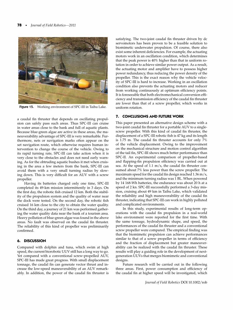
Figure 15. Working environment of SPC-III in Taihu Lake.
a caudal fin thruster that depends on oscillating propul-sion can safely pass such areas. Thus SPC-III can cruisein water areas close to the bank and full of aquatic plants.Because blue-green algae are active in these areas, the ma-neuverability advantage of SPC-III is very remarkable. Fur-thermore, nets or navigation marks often appear on theset navigation route, which otherwise requires human in-tervention to change the course of the vehicle. Owing toits rapid turning rate, SPC-III can take action when it isvery close to the obstacles and does not need early warn-ing. As for the obtruding aquatic bushes it met when cruis-ing in the area a few meters from the bank, SPC-III canavoid them with a very small turning radius by slow-ing down. This is very difficult for an AUV with a screwpropeller.
Having its batteries charged only one time, SPC-IIIcompleted its 49-km mission intermittently in 3 days. Onthe first day, the robotic fish cruised 12 km. Both the stabil-ity of the propulsion system and the quality of water nearthe dock were tested. On the second day, the robotic fishcruised 16 km close to the city to obtain the water quality.On the third day, a journey of 21 km was performed gather-ing the water quality data near the bank of a tourism area.Heavy pollution of blue-green algae was found in the aboveareas. No fault was observed on the caudal fin thruster.The reliability of this kind of propeller was preliminarilyconfirmed.
6. DISCUSSION
Compared with dolphin and tuna, which swim at highspeed, the current biorobotic UUV still has a long way to go.Yet compared with a conventional screw-propelled AUV,SPC-III has made great progress. With small displacementtonnage, the caudal fin can generate vector thrust and in-crease the low-speed maneuverability of an AUV remark-ably. In addition, the power of the caudal fin thruster is
satisfying. The two-joint caudal fin thruster driven by dcservomotors has been proven to be a feasible solution tobiomimetic underwater propulsion. Of course, there alsoexist some inherent deficiencies. For example, the actuatingmotors work in an oscillation condition, which determinesthat the peak power is 40% higher than that in uniform ro-tation in order to achieve similar power output. As a result,the actuating motor and amplifier have to possess higherpower redundancy, thus reducing the power density of thepropeller. This is the exact reason why the vehicle veloc-ity of SPC-III is hard to increase. Working in an oscillationcondition also prevents the actuating motors and reducerfrom working continuously at optimum efficiency points.It is foreseeable that both electromechanical conversion effi-ciency and transmission efficiency of the caudal fin thrusterare lower than that of a screw propeller, which works inuniform rotation.
7. CONCLUSIONS AND FUTURE WORK
This paper presented an alternative design scheme with atwo-joint caudal fin thruster for a portable AUV to a single-screw propeller. With this kind of caudal fin thruster, thedisplacement of a SPC-III robotic fish is 47 kg and its lengthis 1.75 m. The caudal fin thruster accounts for only 7%of the vehicle displacement. Owing to the improvementon the mechanical structure and motion control algorithmof the tail fin, SPC-III shows much better performance thanSPC-II. An experimental comparison of propeller-basedand flapping-fin propulsion efficiency was carried out atsea. At the speed of 1.1 m/s, the caudal fin thruster con-sumed about 7% less power than the screw propeller. Themaximum speed for the caudal fin design reached 1.36 m/s,and the minimum turning radius was 1 BL. When poweredby 14 168-Wh batteries, the endurance was about 20 h at aspeed of 2 kn. SPC-III successfully performed a 3-day mis-sion, cruising about 49 km in Taihu Lake, which validatedthe reliability and high maneuverability of the caudal finthruster, indicating that SPC-III can work in highly pollutedand complicated environments.
In this study, experimental results of long-term op-erations with the caudal fin propulsion in a real-worldlake environment were reported for the first time. Withthe same tonnage, hydrodynamic shape, and speed, theperformances of the caudal fin thruster and a conventionalscrew propeller were compared. The empirical finding wasthat the biomimetic propulsion can achieve performancessimilar to that of a screw propeller in terms of efficiencyand the fraction of displacement but greater maneuver-ability can be realized with the caudal fin thruster. Theseresults will play a guiding role in the development of next-generation UUVs that merges biomimetic and conventionaldesigns.
Future research will be carried out in the followingthree areas. First, power consumption and efficiency ofthe caudal fin at higher speed will be investigated, which
Journal of Field Robotics DOI 10.1002/rob

Liang et al.: Development of a Two-Joint Robotic Fish for Real-World Exploration • 79
requires servo drive systems with higher power densitiesto be developed. Second, an adaptive control algorithm ofthe caudal fin that adjusts flapping movements accordingto the dynamics of the surrounding fluid will be explored.Third, movements in three-dimensional space will berealized with multiple pectoral fins that generate vectorthrust. These promising research directions will producesome useful and exciting results in the near future.
APPENDIX: INDEX TO MULTIMEDIA EXTENSIONS
The videos are available as Supporting Information in theonline version of this article.
Extension Media type Description
1 Video The screw-driven UUV swimmingat 1.1 m/s with rotationalspeed of 5 rps
2 Video SPC-III robotic fish swimming at1.0 m/s with flappingfrequency of 2 Hz
3 Video SPC-III performing fast turningwith small radius
ACKNOWLEDGMENTS
The research work on the screw propeller was conductedwith the help of the China Ship Scientific Research Cen-ter (CSSRC). The authors would like to thank the refereesfor careful reading of the manuscript and for their valuablecomments.
REFERENCES
Anderson, J. M., & Kerrebrock, P. A. (1997, September). Thevorticity control unmanned undersea vehicle (VCUUV)—An autonomous vehicle employing fish swimming
propulsion and maneuvering. In Proceedings of 11th In-ternational Symposium on Unmanned, Undeterred Sub-mersible Technology, Durham, NH (pp. 189–195).
Anderson, J. M., Streitlien, K., Barrett, D. S., & Triantafyllou,M. S. (1998). Oscillating foils of high propulsive efficiency.Journal of Fluid Mechanics, 360, 41–72.
Barrett, D. S., & Triantafyllou, M. S. (1999). Drag reduction infish-like locomotion. Journal of Fluid Mechanics, 392, 183–212.
Chen, D., Wang, T., Liang, J., & Wang, T. (2008, February). Thedesign and application of a sUAV system for Antarcticexpedition. In Proceeding of the 2008 International Con-ference on Robotics and Biomimetics, Bangkok, Thailand(pp. 1129–1134).
Hu, H., Liu, J., Duks, I., & Francis, G. (2006, October). De-sign of 3D swim patterns for autonomous robotic fish. InProceedings of the 2006 IEEE/RSJ International Confer-ence on Intelligent Robots and Systems, Beijing (pp. 2406–2411).
iRobot Maritime Robots—Transphibian (2010). Retrieved May20, 2010, from http://www.irobot.com/gi/maritime/Transphibian/.
Liang, J., Wang, T., Wang, S., Zou, D., & Sun, J. (2005,August). Experiment of robofish aided underwater ar-chaeology. In Proceeding of the 2005 International Confer-ence on Robotics and Biomimetics, Hong Kong (pp. 231–235).
Mbemmo, E., Chen, Z., Shatara , S., & Tan, X. (2008, May).Modeling of biomimetic robotic fish propelled by an ionicpolymer–metal composite actuator. In Proceedings of the2008 IEEE International Conference on Robotics and Au-tomation, Orlando, FL (pp. 689–693).
Wang, T., & Liang, J. (2005, August). Stabilization based designand experimental research of a fish robot. In Proceedingsof the 2005 IEEE/RSJ International Conference on Intel-ligent Robots and Systems, Edmonton, Canada (pp. 954–959).
Ying, L., & Zhu, J. (2006). Screw design and implementation oncomparison UUV (Tech. Rep. 20070145). China Ship Sci-entific Research Center.
Journal of Field Robotics DOI 10.1002/rob