Embed Size (px)
Citation preview

DEVELOPMENT OF A SMALL BLOWER-TYPE WIND TUNNEL
FOR EDUCATIONAL PURPOSES
András Gulyás1, Márton Balczó
2 1student,
2MSc, assistant research fellow
1,2Theodore von Kármán Wind Tunnel Laboratory, Department of Fluid Mechanics,
Budapest University of Technology and Economics (BME), Budapest, Hungary
ABSTRACT
In this paper we describe the design, construction and flow field evaluation of a small low-speed wind tunnel intended mainly for educational use. The wind tunnel has interchangeable test sections with cross sections of 0.35×0.35 m, 0.4×0.5 m and 0.15×1 m. The latter allows the testing of two-dimensional flow phenomena. During the construction stress was laid upon the choice of cheap off-the-shelf components to create an affordable and compact wind tunnel available to higher education laboratories with low budget and limited space.
The flow field evaluation confirmed that the tunnel is suitable not only for educational, but also for certain scientific measurements. Turbulence intensity in the test section is 0.8%, flow inhomogeneity lies mostly below 3%. To achieve these values, the original fan and wind tunnel design had to be modified based on measurements and CFD simulations. INTRODUCTION
The Theodore von Kármán Wind Tunnel Laboratory operates 3 large wind tunnels with cross sections between 1.25 to 5 m2, and wind speeds up to 60 m/s. However, in several measurements (e.g. anemometer calibrations, experimenting with basic fluid dynamics phenomena, initial testing on simplified small scale models), this size is not necessary, and the tunnels are costly and more difficult to operate. Also the equipment needed for moving probes in the test section is more complex, see the large traversing system developed by Varga [1]. To overcome these limitations, we decided to build new small wind tunnels sufficing the following requirements:
- Modular construction for easy transportation - Interchangeable test sections for different purposes - One test section for investigating two-dimensional flows - One test section with 0.5m width (to be able to use earlier wind tunnel
models and the in-development moving terrain simulator belt) - Possibility of fully automatic operation and remote control - Use of off-the-shelf components wherever possible - Use of existing centrifugal fans left from an earlier project.
Basic considerations
First the wind tunnel type and main dimensions were chosen. Despite some gains in energy consumption, closed return was dropped due to its large size. An open return NPL (Eiffel)-type tunnel cannot be used with open test section, and the test section is

under low pressure, which makes its access a bit more difficult, and also can require adjustable wall to control the pressure gradient. Finally an open-return, blower-type tunnel was selected with the following advantages:
- short length - free choice between open or closed test section - no recirculation, thus injection of tracers, sand, water in experiments does
not pollute the internal surface and components of the wind tunnel.
Fig. 1
Wind tunnel layout and components. Top: with 0.35×0.35m test section. Bottom: with 1×0.15 m (2D) test section
DESIGN OF THE WIND TUNNEL In the design process we mainly used literature data. The design and construction issues of low speed wind tunnels are in detail described by Barlow et al. [2] as well as Mehta and Bradshaw [3]. Construction reports of recently built wind tunnels were also reviewed [4-5].
Size of the planned test sections was selected based on the volume flow rate of the existing fan (approx. 3 m3/s). The fan was left from an earlier project. Another requirement was that the dynamic pressure should be in the range of few hundred Pa to be measurable with existing transducers. From the size of the test sections and from the aimed contraction ratio of at least 4, the cross-section of the settling chamber was selected to 1×1m (Table 1).
In the following the individual components of the wind tunnel are discussed.

Table 1 Planned contractions and test sections
Size (W x H x L )
[m] Contraction ratio [-]
Maximum test section velocity [m/s]
Designation
A 0.35×0.35×1 8.16 24 “high-speed” B 0.15×1×1 6.67 19.5 “2D” C 0.5×0.4×1 5 15 “wide”
Inlet, fan and guiding vanes
The Helios F400 BKD 560/4/80/50 rectangular-channel centrifugal fan is driven by a 4.8 kW asynchronous motor using a Yaskawa V1000 frequency converter requiring 3-phase 32 A fusing. (In practice, 3×16 A was sufficient.)
During the first tests it showed that the flow at the outlet is non-homogeneous in both magnitude and flow angle. CTA measurements also indicated strong flow switching-like velocity fluctuations of <1Hz frequency. To overcome this, guiding vanes were designed, manufactured and attached to the outlet cross section of the fan. The outlet flow velocity at the guide vanes was measured then using a handheld thermal anemometer, proving the improvements caused by the installed vanes (Fig. 2).
Fig. 2
Left: Modifications of the fan. Top right: the original fan (opened for inspection) Bottom right: velocity distribution at the outlet without and with guide vanes.
Further improvement was achieved by changing the direction of the inlet flow to symmetrical. The upper plate was removed and a bell mouth was mounted to the top. The original horizontal inlet opening was closed. To fully avoid the above mentioned

temporal fluctuations, cylindrical plates were mounted into the originally rectangular housing of the fan, forming a streamlined inner housing, as it can be seen in Fig. 2.
Diffuser
To further homogenize the flow with possibly small pressure loss, the flow cross section after the fan must be increased. To do this in a reasonably short length, a wide angle diffuser of 40° full angle has been chosen. Although diffuser usually tend to separate at this angle, according to Barlow et al. [2] and Sahin et al. [6] this can be avoided when using turbulence screens inside the diffuser. (Separation in a wind tunnel should be avoided by all means as it introduces new inhomogeneity to the flow.) However, the wide angle diffuser with turbulence screens installed at the inlet and in the middle (Fig. 3) still operated in separation, supposedly because of the disturbed inlet boundary conditions.
In a second attempt a split diffuser was designed. Two setups, one with flat (1) and another with curved (2) splitter plate was simulated previously using FLUENT, from which the first one proved to be more efficient and able operate without separation.
Fig. 3 Left: FLUENT simulation of the split diffuser, top: with curved, bottom: with flat
splitter plate. Right: outlet of the split diffuser realized
Settling chamber
The settling chamber consists of commercially available ventilation channel elements of 1×1 m size with stainless steel screens glued and bolted between them as well as a channel element with an aluminum honeycomb structure. The elements are due to their mounting on an aluminum profile track, can be easily shifted, replaced and extended.
The most advantageous arrangement of these turbulence reduction devices was analyzed by Sheiman and Brooks [7] in a series of experiments. They confirmed the well known fact that honeycombs act as flow straighteners and can reduce the lateral fluctuations. Wire meshes with an area ratio (free cross section vs. full cross section) larger than 50% damp both the main and the lateral flow components at the cost of a higher pressure loss. The combination of one honeycomb and several screens of different mesh size chosen for the new wind tunnel can be taken from Table 2.
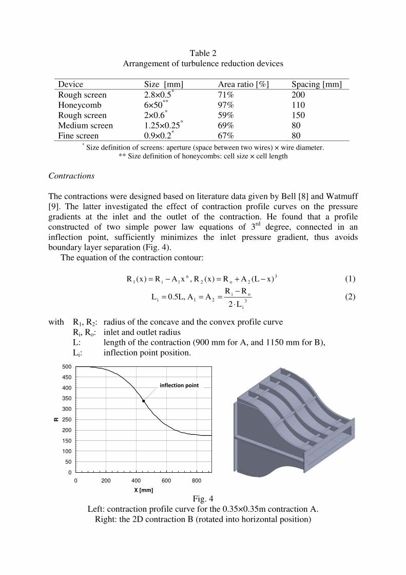
Table 2 Arrangement of turbulence reduction devices
Device Size [mm] Area ratio [%] Spacing [mm] Rough screen 2.8×0.5* 71% 200 Honeycomb 6×50** 97% 110 Rough screen 2×0.6* 59% 150 Medium screen 1.25×0.25* 69% 80 Fine screen 0.9×0.2* 67% 80
* Size definition of screens: aperture (space between two wires) × wire diameter. ** Size definition of honeycombs: cell size × cell length
Contractions
The contractions were designed based on literature data given by Bell [8] and Watmuff [9]. The latter investigated the effect of contraction profile curves on the pressure gradients at the inlet and the outlet of the contraction. He found that a profile constructed of two simple power law equations of 3rd degree, connected in an inflection point, sufficiently minimizes the inlet pressure gradient, thus avoids boundary layer separation (Fig. 4).
The equation of the contraction contour:
32o2
n1i1 )xL(AR)x(R,xAR)x(R −+=−= (1)
3
i
oi21i
L2
RRAA,L5.0L
⋅
−=== (2)
with R1, R2: radius of the concave and the convex profile curve Ri, Ro: inlet and outlet radius L: length of the contraction (900 mm for A, and 1150 mm for B), Li: inflection point position.
0
50
100
150
200
250
300
350
400
450
500
0 200 400 600 800
X [mm]
R
Fig. 4 Left: contraction profile curve for the 0.35×0.35m contraction A.
Right: the 2D contraction B (rotated into horizontal position)
inflection point

Construction details
The wind tunnel is mounted on several steel frames with wheels and adjustable feet. Test sections, the fan, and the diffuser-settling chamber-contraction cone assembly can be disconnected and moved easily. The closed test sections are built of an aluminum profile system allowing easy mounting of ancillaries, and have opening acrylic windows for visual access (laser sheet, LDV, PIV). Contraction A was built of composite polymers, contraction B of water-cut wooden ribs and thin bent aluminum sheets. Construction costs summed up to about 10.000 Euro, including the fan. FLOW FIELD EVALUATION For the evaluation of the flow quality of the new wind tunnel, a one-component hotwire anemometer (CTA) system with a Dantec (DISA) 55M measurement bridge was used. Output signal of the CTA was connected to an NI PCI 6036E A/D converter. The hotwire probe arm was mounted on a two-component Cartesian traversing system, controlled by an ISEL motion controller and LabVIEW. Discussion of results
The measurement of the contraction A was performed at 23 m/s mean velocity with open test section. Inhomogeneity of the flow velocity U is expressed as
[%]100U
UUU ⋅
−=δ (3)
Fig. 5 shows interpolated results from the measurement grid of 27×27
measurement points.
Fig. 5
Left: Measurement of flow homogeneity at the outlet of contraction A. Right: interpolated velocity inhomogeneity. Black dots show the measurement grid

In the upper right corner, up to 2% higher velocities and at the lower left 1% lower velocities can be observed. The boundary layer is approx. 15mm wide with the unfortunate exception of the left side, where it is a bit wider. Turbulence in the middle of the test section was 0.8%.
In Fig. 6, flow inhomogeneity at the outlet of the B contraction (2D contraction) is compared to CFD simulations performed earlier. Mean wind velocity was 15.7 m/s. Please note that the figure is rotated by 90 degree to the right. It is obvious that the real inhomogeneity could not be captured by the simulation, might it be due to the turbulence model (k-ω SST) or the non-homogeneous inlet boundary condition coming from the settling chamber. Flow velocities are clearly smaller at the left side than on the right, the differences range from -3.5 to +2.5%. At the top (right side of the image) velocities are slightly higher than at the bottom (left side of the image)
Both velocity distributions suggest that independently from which of the contraction cones (A or B) is used, the flow rate at the upper right quarter of the settling chamber cross-section is slightly higher. The cause of this might still be a (slightly) asymmetric outflow from the split diffuser; however, this can be improved by the addition of one or two screens in the settling chamber.
Fig. 6
Flow homogeneity at the outlet of the 1×0.15 m contraction B. Top: FLUENT simulation. Bottom: CTA measurement. Note that the figure is rotated by 90°
CONCLUSION AND OUTLOOK
In this project we successfully designed and built a modular, small scale, low-speed wind tunnel and evaluated it for educational purposes. The next step is the development of laboratory measurements in a wide range of basic fluid dynamic phenomena, vehicle, building and environmental aerodynamics. These include in test section A and C the measurement of aerodynamic forces acting on simple bodies using load cells, the measurement of lift and drag on vehicle models with moving terrain simulation, and the study of ground effect, flow around simple building shapes, and tracer dispersion from a point source. In the two-dimensional test section B we plan the measurement of airfoils, slats, flaps, boundary layer control of wings, static and
dynamic testing of bridge section models, the investigation of blade rows, and fluid dynamic effects like the Coanda-effect or the Magnus-effect (Flettner rotor model). ACKNOWLEDGEMENTS
The significant contributions of our BSc/Msc graduates Balázs Alpár, Péter Kurdi and Benedek Károlyi are gratefully acknowledged. We also wish to thank the following institutions of the Budapest University of Technology and Economics for their kind support: Department of Polymer Engineering, University Student Association, Mechanical Engineering Faculty Student Association, Mechanical Engineering Special College, as well as Budapest Sewage Works pte Ltd, Kraft-Foods Hungária Ltd and Kamleithner Budapest Ltd.
The support of the projects K 108936 “Flow and dispersion phenomena in urban environment” of the Hungarian Scientific Research Fund and the New Széchenyi Plan project TÁMOP-4.2.1/B-09/1/KMR-2010-0002 is acknowledged. The fan used was originally purchased for the GVOP-3.1.1.-2004-05-0202/3.0 project and kindly made available to us by hon. associate professor dr. Gábor Koscsó. REFERENCES
[1] VARGA, Á: Development of a probe traversing system for an open test
section wind tunnel. - Gépészet 2012: Proceedings of the eighth international conference on mechanical engineering. Budapest University of Technology and Economics, May 24-25, 2012. pp. 579-586.
[2] BARLOW, J.B., RAE, W. H., POPE A.: Low-Speed Wind Tunnel Testing. -
John Wiley & Sons, 3rd Ed., 1999. [3] MEHTA, R.D. BRADSHAW, P.: Design rules for small low speed wind
tunnels. - The Aeronautical Journal of the Royal Aeronautical Society, November 1979, p.443-449.
[4] FIEDLER, M., BOBRUTZKI, K., SAMER , M., BERG, W.: New wind tunnel
facility in agricultural research. - PHYSMOD2011 – International Workshop on Physical Modeling of Flow and Dispersion Phenomena, KlimaCampus, University of Hamburg, Germany – August 22-24, 2011.
[5] LINDGREN, B., JOHANSSON, A. V.: Design and Evaluation of a Low-Speed Wind-Tunnel with Expanding Corners. Technical Reports from Royal Institute of Technology Department of Mechanics, Stockholm, Sweden, October 2002.
[6] SAHIN, B., WARD-SMITH, J., LANE, D.: The pressure drop and flow
characteristics of wide-angle screened diffusers of large area ratio. - Journal of Wind Engineering and Industrial Aerodynamics 58 (1995) p. 33-50.
[7] SCHEIMAN J., BROOKS, J. D.: Comparison of Experimental and
Theoretical Turbulence Reduction from Screens, Honeycomb, and
Honeycomb-Screen Combinations. - AIAA paper 80-0433R. Journal of Aircraft Vol. 18, No. 8, August 1981, p. 638-643.
[8] BELL, J.H., MEHTA, R.D.: Contraction design for small low-speed wind
tunnels. - NASA Contractor Report, 1988, CR-182747. [9] WATMUFF, J.H. : Wind Tunnel Contraction Design. - 9th Australasian
Fluid Mechanics Conference, New Zealand, Auckland, 1986 p. 472-475.