Embed Size (px)
Citation preview

* Corresponding author, tel: +234 – 806 – 067 – 6748
DEVELOPMENT OF A BOOLEAN LOGIC SIMULATOR BASED
ON QUINE MCCLUSKY ALGORITHM
I. Oghogho1,*, H. Agada2 and A. M. Obiazi3 1, DEPARTMENT OF ELECTRİCAL & ELECTRONİC ENGİNEERİNG, DELTA STATE UNİVERSİTY, ABRAKA-OLEH CAMPUS,
DELTA STATE, NİGERİA 2, DEPT OF ELECTRİCAL & INFORMATİON ENGR’G, LANDMARK UNİVERSİTY, OMU-ARAN, KWARA STATE, NİGERİA
3, DEPT OF ELECTRİCAL & ELECTRONİC ENGR’G, AMBROSE ALLİ UNİVERSİTY, EKPOMA, EDO STATE, NİGERİA
E-mail addresses: [email protected], [email protected], 3 [email protected]
ABSTRACT
This paper presents the development of an educational simulation tool for solving Boolean logic
equations using Quine McCluskey’s algorithm. Unity3D development environment was used to
provide an interface for the design of the software front end. A custom built version of Javascript
was used to write the back end code that drives the algorithm. Based on the output parameters
decided on by the user for either sum of product (SOP) or product of sum (POS) approaches, the
software provides an interactive user interface displaying: (i) the truth table with a maximum of
six inputs (ii) the Karnaugh Map as well as the generated corresponding simplified logic equation
and (iii) the generated logic circuit diagram. The results of the simplified Boolean expressions and
logic circuits generated by the developed tool were compared with manually calculated solutions
and available html and console based implementations and were found to be accurate.
Keywords: Boolean Logic Simulator, Logic Circuit, Quine McClusky Algorithm, Karnaugh Map, Digital
Electronics.
1. INTRODUCTİON
Digital Electronics covers Boolean logic expressions,
their simplification, their representation in truth tables
and how to plot functional logic circuit diagrams based
on a desired predetermined result [1]. Further down
the course, several methods of logic simplification for
the reduction of more complex expressions are
introduced. The process generally involves the
dissolution of redundant components of the
expressions with the use of Boolean arithmetic or
graphical methods like Karnaugh maps. In many
applications, it is required that a Boolean equation is
solved while excluding irrelevant variables [2, 3].
The five key elements in Boolean logic simplification
are:
(i) the truth table, which expresses output states
based on all possible permutations of variable
input states,
(ii) the min/max term, which is a simple way of
describing the system’s “ON” states, as expressed
by the truth table
(iii) the Karnaugh map, which is a graphical method of
simplifying Boolean equations,
(iv) the simplified Boolean expression, which is the
shortest and most logical expression for the
desired outputs with all permutations of inputs for
the system, and
(v) the circuit diagram, which is the final logic circuit
that satisfies any logic equation.
Digital circuit designers use Boolean algebra as the
basic formal system while digital circuits are the end
results they seek to produce. Typically, the complexity
of the raw expressions derived from truth tables and
in most cases, the final decomposed algorithms,
increases exponentially with the number of variables
Nigerian Journal of Technology (NIJOTECH)
Vol. 38, No. 3, July 2019, pp. 716 – 725
Copyright© Faculty of Engineering, University of Nigeria, Nsukka, Print ISSN: 0331-8443, Electronic ISSN: 2467-8821
www.nijotech.com
http://dx.doi.org/10.4314/njt.v38i3.25

DEVELOPMENT OF A BOOLEAN LOGIC SIMULATOR BASED ON QUINE MCCLUSKY ALGORITHM, I. Oghogho, et al
Nigerian Journal of Technology, Vol. 38, No. 2, July 2019 717
in question. Because of this, the manual computation
of systems with higher variable counts is extremely
tedious and cumbersome even with the use of
simplified methods like the Karnaugh map. Lecturers
and students alike have a hard time simulating larger
systems in class during teaching sessions due to time
constraints. Examples in class only border around
simplistic circuit designs with no more than four
variable inputs and most students of the subject never
get to fully understand the concepts of Karnaugh
mapping, or grasp the correlation between the key
elements in Boolean logic simplification for more than
four variables.
It is therefore necessary to create a learning tool
which assists both students and their teacher, to easily
and effectively simulate simple and complex Boolean
equations, and visualize the simplification using
Karnaugh maps and the final logic circuit diagram. This
will enable the visual assessment of the correlation
between each of the elements mentioned above
without the need for cumbersome manual calculation.
A Boolean function simplification algorithm such as the
Quine McCluskey algorithm [4] and a robust
programming interface such as the Unity engine
makes this possible.
1.1 Review of Past Work
Boody [5] created a Quine McCluskey Calculator
launched on PlayStore in 2012 using Java
implementation of the algorithm. Boody [5]
implementation allowed users to calculate for don’t
care values and showed the “Prime Implicants” (PI)
charts as they were processed. However the version
was limited to 4 variables and focused only on
preparing the Karnaugh map and final result. It did not
have the functionality of visualizing the resulting circuit
diagram at a fast refresh rate.
Cits [6] developed a Karnaugh Veitch Diagram (KVD)
calculator which calculated up to five variables based
on Quine McCluskey implementation.KVD calculator
displays the PI chart calculation and has a remarkable
refresh rate between calculations. İts results were the
most accurate of all the programs sampled for this
review, although it does not generate circuit diagrams.
Abdelrahman [7] developed an implementation of
Karnaugh map minimizer for infinite variables using
C++. The C++ code is relatively compact but does not
have an explicit user interface which is an obvious
disadvantage for achieving real time visual learning.
Although the implementation gives the user the ability
to input an infinite number of variables for calculation,
processing limits is dependent on the power of the
computer’s processor.
GatePlus developed in this work provides a well
presented, simple to use simulator for Boolean logic
operations for up to six variables. It provides a tool for
simple computation and graphical visualization of the
results of logic functions and their corresponding
circuit diagrams. Users will be able to easily see the
results of any modifications they make, or any new
methods they wish to employ. This tool will effectively
make the study of Boolean logic functions easier, more
interactive and practical.
1.2 Objectives of Study
The aim of this work was to design and develop a
simple-to-use application for the simplification of
Boolean logic expressions which will be optimized for
User experience (UX) and User Interface (UI) design.
The objective was to create a learning tool which
assists both students and their teachers without the
need for manual calculations to:
(i) easily and effectively simulate simple and complex
Boolean equations,
(ii) visualize both the simplified logic equation and the
Karnaugh maps solution
(iii) visualize in real-time circuits resulting from their
design specifications, so that they can fine-tune
and apply corrections in real time.
2. MATERİAL AND METHODS
The design used Unity3D development environment
which provided an interface for the design of the front
end of the software. Details on the Unity3D are found
in [8]. Its development environment was specifically
designed to handle highly flexible 2D and 3D graphics
in Cartesian virtual space, but most of those tools are
used in improvisation for the building of the graphical
user interface of the software.
A custom built version of Javascript (Unityscript) was
used to write the back end code that drives the
algorithm. JavaScript code works at the back end for
driving the dissolution of redundancy in the raw output
from the truth table using the Quine-McCkluskey
algorithm. The software provides an interactive user
interface with three scrollable panels displaying:
(i) the truth table with a maximum of six inputs
(ii) the Karnaugh Map as well as the generated
corresponding simplified logic equation.
(iii) the generated logic circuit diagram.
The logic conditions can be varied either on the truth
table or on the Karnaugh Map panels while the logic
equations and circuit diagrams of the simplified

DEVELOPMENT OF A BOOLEAN LOGIC SIMULATOR BASED ON QUINE MCCLUSKY ALGORITHM, I. Oghogho, et al
Nigerian Journal of Technology, Vol. 38, No. 2, July 2019 718
expressions are automatically generated from the
output parameters decided on by the user for either
sum of product (SOP) or product of sum (POS)
approaches. The software tool is capable of working
on multiple solutions on different tabs at the same
time. Fig 1 shows the Unity3D development
environment with GatePlus in active development.
2.1 Project Mockup
The drafting of a mock-up for the interface of the
software can be done in any graphics compositing
software. Adobe Photoshop was chosen for its
flexibility. Before the digital drafting, it is advisable to
analyse the optimal configuration for the software
interface to deliver all the information to the user in
the most minimal way, without cluttering the screen.
This can easily be resolved by understanding the
required functionality and drafting the cardinal
functions. For GatePlus, these functions are:
i. The display of all possible combinations of input
states for all current input variables, and the
resulting output for that configuration. This
functionality clearly requires the need of a Truth
Table within the software interface. It will be
preferable if this element is non-collapsible as it
displays critical information that may need to be
visible at all times.
ii. The visualization of the active circling of variable
interpretations within a Karnaugh Map, so the
user can see the graphical resolution of the
equation generated from the truth table. The
user must also be able to edit the output directly
from the k-map, so as to be able to visually alter
the outcomes of the truth table to simulate
theories the user might have, or physically refine
the Boolean relationship to generate a more
favourable result.
iii. The software program must be capable of
automatically generating a Logic Circuit Diagram
based on the final solution. This element will
require a lot of screen real-estate and needs also
to be non-collapsible as the essence of the entire
project is that the user should be able to at all
times, visualize the dynamics in the nature and
size of the circuit while altering ouput
requirements.
iv. The software must have the functionality of
toggling between Sum Of Product (SOP) and
Product Of Sum (POS) calculations for output
states. When SOP is selected, the on-state
variables are active while the off-state variables
are inactive, and vice-versa for POS calculations.
This brief analysis shows that the most flexible
configuration for the software would be to have three
major panels. These panels will need to be enclosed in
scrollable spaces to improve the software’s screen
real-estate management. Depending on the
complexity of the solution being handled per time, the
size of the enclosed scroll spaces will change (expand
or contract) to accommodate the data being handled.
This will be handled by unity’s BeginScrollView() and
EndScrollView() classes.
Figure 1: Unity3D development environment with GatePlus in active development.

DEVELOPMENT OF A BOOLEAN LOGIC SIMULATOR BASED ON QUINE MCCLUSKY ALGORITHM, I. Oghogho, et al
Nigerian Journal of Technology, Vol. 38, No. 2, July 2019 719
Figure 2: Mock-up for software interface of GatePlus.
Each scrollable space will also have a panel above it
for simple configurations and information display. For
instance, the title bar of the Truth Table will have
options for choosing the number of variables,
inverting the output (useful for resetting the table to
no output immediately after a POS-SOP switch),
resetting the solution or choosing from a list of pre-
set solutions. The Logic Circuit Diagram title bar will
also have options for toggling colour and grid on or
off. Figure 2 shows the original project mockup for
GatePlus 1.0.
Although the project Mockup of Figure 2 gives the
developer a great deal of advantage in understanding
the final product he is working towards, it has its
limitations. As the project is mostly unstarted when
the Mockup is designed, the developer might be
unaware of some intrinsic details related to what
might be required to be displayed on the interface, or
what problems may arise in implementing some of his
decisions. In retrospect to having completed the
development of the software program, below are a
few elements of the final application that did not
appear in the Mockup.
(i) The addition of inverting gates (NOT gates) to each
input line of the Logic Circuit Diagram to ease
processing involved in the otherwise cumbersome
method of using “symbology” to represent non-
intersection between input lines when they are
crossed, and channelling the input into the
inverting gate right before it goes into the first layer
of logic. Prior to the design, the added computing
required to calculate for the small but vastly
repeating non-intersecting elements in the circuit
were not put into consideration.
Figure 3: Mockup concept of variable roots in circuit
diagram.
Figure 4: Actual implementation in final software
design.
In the final actualization, two tiny buttons were added
to the edge of each scrollable panel, between the
vertical and horizontal scrollbars, and at border
intersection points, to help the user navigate quickly
to the top-left and bottom-right corners of the

DEVELOPMENT OF A BOOLEAN LOGIC SIMULATOR BASED ON QUINE MCCLUSKY ALGORITHM, I. Oghogho, et al
Nigerian Journal of Technology, Vol. 38, No. 2, July 2019 720
scrollable space when working with large spaces
during more complex calculations. This was not
considered in the conceptualization phase.
(ii) In the chosen “symbology”, capital roman
alphabets were used to represent input variables,
with horizontal accent bars symbolizing an off-
state or null value. In the actual implementation,
plain capital roman alphabets were used to
represent on-states, while small letters were
used to represent off states. This is conventional
in software implementations of Karnaugh maps,
and was also utilized in this project to simplify
programming and to reduce the processing
involved in appending the accent bars to each
off-state element in the map and circuit.
(iii) Two labels displaying grey-code and zero-
indexed positions of each block in the
Karnaughmap were added during active
development.
(iv) A simple button for the addition of new tabs was
also omitted in the project Mockup.
2.2 Project Checklists
This subsection describes the checklisting of key
objectives that will need to be implemented for the
software to execute its functions optimally. Each
checklist serves as a landmark in the development
process and systematically guides the design of the
software to a desired finish. Below are the cardinal
objectives that had to be implemented serially for the
software to execute properly.
2.2.1 Variable definition
The mainEngine.js script that contains most of the
code that drives GatePlus contains over 200 variable
definitions for Arrays, lists, integers, doubles,
textures, GUI elements, vectors, Booleans and strings.
One cannot possibly know every single variable
necessary to develop the software from the start.
Variables must constantly be created during the
development process to fulfil constituent tasks as
they arise.
2.2.2 Easy selection of number of variables to
work with.
Users can work with between 2 and 6 input variables:
This was implemented using a single integer variable
labelled internally as no Of Parameters with a default
value of 2.
2.2.3 Automatically formatted truth table with
editable output variables
This is one of GatePlus’s more robust features. The
truth table panel is nested within a Scrollable space
implemented by calling the inbuilt function, GUI.
BeginScrollView () from within the OnGUI () function,
the cardinal function that controls the display of all
GUI elements in Unity. GUI. Draw Texture () is used
to create the visual elements of the table while a
complex chain of loops helps to generate and control
the dynamics of the binary numbers that express the
possible permutations of configurations of input
variable states, as well as the dynamics of the table’s
form as the number of variables (no Of Parameters)
changes. Finally, the output values toggle from on-
state to off-state by the use of invisible buttons
behind the text, with a Boolean control.
2.2.4 Editable, realtime, self-solving Karnaugh
map
This is another robust feature of GatePlus, whose
intricate details cannot possibly be explained in its
entirety in one subsection. The script is nested in a
similar manner as that explained above for the truth
table. The circling of PIs is controlled by a reverse-
engineering process due to the complexities involved
in programming a linear system to compute the
torus-shaped continuity characteristics of the
Karnaugh map. The reverse-engineering process is
realized by writing a custom function to interpret the
linear results from the Quine-McCluskey algorithm to
circled groups, and apply the correct outline at the
right position, to the Karnaugh map. The circle
shapes are colour-coded to aid their visibility: green
for unit or square groups, red for vertical groups,
yellow for horizontal groups and blue for groups that
circle virtually due to torus characteristics, but not
always physically.
2.2.5 Easy toggling
Between Product of Sum (POS) and Sum of Product
(SOP) states: This is realized using a single button on
the top-left corner of the Karnaughmap. About three
if-loops running in the update function tap out of the
Boolean output of this function to ensure that its
results are translated to all elements of the software
that need to be altered when the switch is toggled.
These elements include (but are not limited to)
toggling the string stating the Boolean parameters
from min to max terms or vice-versa, toggling the

DEVELOPMENT OF A BOOLEAN LOGIC SIMULATOR BASED ON QUINE MCCLUSKY ALGORITHM, I. Oghogho, et al
Nigerian Journal of Technology, Vol. 38, No. 2, July 2019 721
values to be considered from the truth table to off-
state variables in the case of POS or on-state for SOP
variables and expressing the simplified Boolean
expression in the appropriate form.
2.2.6 Switch for inversion of output variables
for sake of ease of implementation of same results
from SOP to POS and vice versa without having to
start afresh. This is implemented in a single custom
function called invert() which is called whenever one
of the invert buttons on the interface is clicked.
2.2.7 Switch for resetting output variables to
their default values in POS or SOP form. This is
implemented in a single custom function called
reset() which is called whenever one of the reset
butons on the interface is clicked.
2.2.8 Dynamic circuit diagram (adjusts itself
automatically to display the results of the Karnaugh
map).
2.2.9 Multitasking capabilities: Multiple
“renamable” tabs can be opened to handle several
calculations per time. Users can work with between 1
and 5 renamable tabs.
2.2.10 Professional software interface: The
software must meet professional standards for
presentation and user experience. The interface
design is themed after Adobe Photoshop CS6. Several
functions and design specifications are implemented
to make the software meet the required standards
namely:
a. Smooth-scroll buttons: To take the scroll-
space directly to the top or bottom with the click
of a simple button.
b. Guiding animations: The tabs slide out to
show that a new tab has been created, or slide
in to show that a tab has been destroyed.
c. Colour signalling: The colours of certain icons
or elements change to show that they are in
focus or that your attention is needed (e.g. blue
for focus, and grey for latency on the tab
buttons). This is especially used in the Karnaugh
map, to indicate the size and scope of circled
regions, or demarcations for laterally inverted
zones.
2.2.11 Status Bar: To display relevant information,
as well as solutions to problems being solved at that
particular session.
2.2.12 Menu Bar: To provide a comprehensive list
of software related options.
2.3 Main Framework of the Driving Code for
the Application’s Functionality
Unity Script works by having very different execution
behaviours for different parts of the script. Below are
descriptions of the execution behaviours of three
major functions that are extremely relevant to the
execution of this project.
2.3.1 Function Mono Behaviour. Start (): void
{}: This function runs anything enclosed within its
curly brackets only once—when the application is
started. This means it is useful for one-time execution
of portions of the code that need only be executed
once, like setting initial states for some variables
(mostly JavaScript arrays). The empty brackets
indicate that this function accepts no input variables
when it is called and returns nothing hence the “void”
after the colon (Note that in Unity Script, the scripting
convention does not permit the actual addition of “:
void” when the function is called. This is mentioned
only for emphasis for the sake of this description).
2.3.2 Function Mono Behaviour. Update ():
void {}: This function runs in a constant loop, on
every frame. A frame is a video-based subdivision of
time during which static elements are displayed on
the screen. Elements change only when a frame
changes, thus creating the illusion of motion. Unity’s
standard is 60FPS (Frames Per Second), so the
update function runs its enclosed script from top to
bottom, sixty times every second. Most of the time-
dependent calculations in the code are executed from
within this function. The function’s unique running
behaviour can also be adopted on other functions by
calling them from within this function.
2.3.3 Function Mono Behaviour. On GUI():
void{}: All operations directly related to the display
of two dimensional graphical elements like labels and
buttons (Virtually the entire interface of the software)
can only from run within this function. This is due to
the peculiar way that GUI elements are processed by
the computer. Depending on the power of the
graphics card and the processor speed, computers
DEVELOPMENT OF A BOOLEAN LOGIC SIMULATOR BASED ON QUINE MCCLUSKY ALGORITHM, I. Oghogho, et al
Nigerian Journal of Technology, Vol. 38, No. 2, July 2019 722
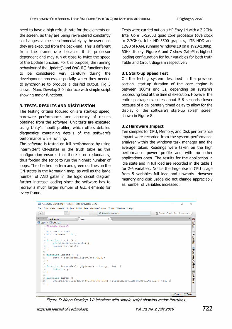
need to have a high refresh rate for the elements on
the screen, as they are being re-rendered constantly
so changes can be seen immediately by the user once
they are executed from the back-end. This is different
from the frame rate because it is processor
dependent and may run at close to twice the speed
of the Update function. For this purpose, the running
behaviour of the Update() and OnGUI() functions had
to be considered very carefully during the
development process, especially when they needed
to synchronise to produce a desired output. Fig 5
shows: Mono Develop 3.0 interface with simple script
showing major functions.
3. TESTS, RESULTS AND DİSİCUSSİON
The testing criteria focused on are start-up speed,
hardware performance, and accuracy of results
obtained from the software. Unit tests are executed
using Unity’s inbuilt profiler, which offers detailed
diagnostics containing details of the software’s
performance while running.
The software is tested on full performance by using
intermittent ON-states in the truth table as this
configuration ensures that there is no redundancy,
thus forcing the script to run the highest number of
loops. The checked pattern and green outlines on the
ON-states in the Karnaugh map, as well as the large
number of AND gates in the logic circuit diagram
further increase loading since the software has to
redraw a much larger number of GUI elements for
every frame.
Tests were carried out on a HP Envy 14 with a 2.2GHz
Intel Core i5-5200U quad core processor (overclock
to 2.7GHz), Intel HD 5500 graphics, 1TB HDD and
12GB of RAM, running Windows 10 on a 1920x1080p,
60Hz display. Figure 6 and 7 show GatePlus highest
loading configuration for four variables for both truth
Table and Circuit diagram respectively.
3.1 Start-up Speed Test
On the testing system described in the previous
section, start-up duration of the core engine is
between 100ms and 3s, depending on system’s
processing load at the time of execution. However the
entire package executes about 5-8 seconds slower
because of a deliberately timed delay to allow for the
display of the software’s start-up splash screen
shown in Figure 8.
3.2 Hardware Impact
Ten samples for CPU, Memory, and Disk performance
impact were recorded from the system performance
analyser within the windows task manager and the
average taken. Readings were taken on the high
performance power profile and with no other
applications open. The results for the application in
idle state and in full load are recorded in the table 1
for 2-6 variables. Notice the large rise in CPU usage
from 5 variables full load and upwards. However
memory and disk usage did not change appreciably
as number of variables increased.
Figure 5: Mono Develop 3.0 interface with simple script showing major functions.

DEVELOPMENT OF A BOOLEAN LOGIC SIMULATOR BASED ON QUINE MCCLUSKY ALGORITHM, I. Oghogho, et al
Nigerian Journal of Technology, Vol. 38, No. 2, July 2019 723
Figure 6: GatePlus Truth Table highest loading
configuration for four variables
Figure 7: GatePlus Circuit Diagram highest loading
configuration for four variables.
Figure 8: GatePlus 1.0 splashscreen.
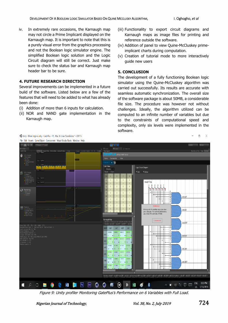
Figure 9 shows Unity profiler monitoring GatePlus’s
performance on 6 variables with full load. The Truth
Table, Karnaugh map, logic equation and Circuit
diagrams provided by GatePlus are also shown in the
diagram.
Table 1: Hardware Performance of GatePlus S/N State CPU (%) Memory(MB) Disk(MB)
1 2 Variables, Idle 8.6 48.3 0.0
2 2 Variables, Full 8.7 48.5 0.1
3 3 Variables, Idle 10.3 48.5 0.0
4 3 Variables, Full 12.4 45.8 0.2
5 4 Variables, Idle 12.9 48.9 0.0
6 4 Variables, Full 13.3 49.0 0.1
7 5 Variables, Idle 18.3 49.4 0.0
8 5 Variables, Full 33.8 49.6 0.2
9 6 Variables, Idle 30.3 50.2 0.2
10 6 Variables, Full 30.4 50.3 0.2
Any change effected by the user on the truth Table or
the Karnaugh map is automatically reflected in real
time in the Boolean logic equation and the circuit
diagram. Notice the sharp rise in CPU processing for 5
variables full and above on Table 1, hence the need
for the warning pop-up shown in Figure 9 which was
expanded in Figure 10.
3.3 Speed and Accuracy Test
GatePlus was tested against hand solved problems and
other logic solvers, and was found to be completely
accurate in both Product of Sum and Sum of Product
implementations. There is absolutely no noticeable
delay between computation changes due to the use of
the update function to call the Quine-McCluskey
solver, and the building of the other essential panels
directly from the results of the continuously
synchronizing solution. However it should be noted
that the simulator was tested on a relatively fast CPU
and a great deal of RAM, so performance may differ
slightly on a different platform.
The results of the simplified Boolean expressions and
logic circuits generated by the developed tool were
compared with manually calculated solutions and
available html and console based implementations and
were found to be accurate and with a better user
friendly graphic User Interface [9, 10].
3.4 Bugs
Below is a list of recorded bugs in GatePlus 1.0
i. The drop-down list for number of variables may
not automatically exit the screen when the user
clicks away from it, as in standard software.
ii. Once the quick-scroll corner-button for the Logic
Circuit scroll space is clicked once before the
scroll space is large enough to require a vertical
scrollbar, the horizontal scrollbar will continue to
orient itself to the right even when pulled away.
This will continue until the vertical scrollbar
appears. This is due to conflict in an exponential
value controlling its animation, and the
screen.length read-only variable. However it
does not at all hinder performance or distract the
user.
iii. There are a few pixel-position-related
inconsistencies with the lines in the Logic Circuit
diagram when some parameters are passed to it.
The diagram is although, still readable, but may
not display conventionally.
DEVELOPMENT OF A BOOLEAN LOGIC SIMULATOR BASED ON QUINE MCCLUSKY ALGORITHM, I. Oghogho, et al
Nigerian Journal of Technology, Vol. 38, No. 2, July 2019 724
iv. In extremely rare occasions, the Karnaugh map
may not circle a Prime Implicant displayed on the
Karnaugh map. It is important to note that this is
a purely visual error from the graphics processing
and not the Boolean logic simulator engine. The
simplified Boolean logic solution and the Logic
Circuit diagram will still be correct. Just make
sure to check the status bar and Karnaugh map
header bar to be sure.
4. FUTURE RESEARCH DIRECTION
Several improvements can be implemented in a future
build of the software. Listed below are a few of the
features that will need to be added to what has already
been done:
(i) Addition of more than 6 inputs for calculation.
(ii) NOR and NAND gate implementation in the
Karnaugh map.
(iii) Functionality to export circuit diagrams and
Karnaugh maps as image files for printing and
reference outside the software.
(iv) Addition of panel to view Quine-McCluskey prime-
implicant charts during computation.
(v) Creation of tutorial mode to more interactively
guide new users
5. CONCLUSION
The development of a fully functioning Boolean logic
simulator using the Quine-McCluskey algorithm was
carried out successfully. Its results are accurate with
seamless automatic synchronization. The overall size
of the software package is about 50MB, a considerable
file size. The procedure was however not without
challenges. Ideally, the algorithm utilized can be
computed to an infinite number of variables but due
to the constraints of computational speed and
complexity, only six levels were implemented in the
software.
Figure 9: Unity profiler Monitoring GatePlus’s Performance on 6 Variables with Full Load.

DEVELOPMENT OF A BOOLEAN LOGIC SIMULATOR BASED ON QUINE MCCLUSKY ALGORITHM, I. Oghogho, et al
Nigerian Journal of Technology, Vol. 38, No. 2, July 2019 725
Figure 10: Warning pop-up when working above 4
variables.
This software can be utilized by students and
professionals for learning purposes and for simple
Boolean simplification for projects they may be
working on. It is easy to use and can be learnt in less
than ten minutes. To the best of our knowledge, the
developed logic simulator tool has an edge over
previous implementations [6, 7, 8, 11] because it
provides a more robust GUI suitable for easy
visualisation and multitasking needed for educational
purposes.
6. REFERENCES
[1] Petrescu, I., Păvăloiu, I., & Drăgoi, G.: Digital
Logic Introduction Using FPGAs. Procedia - Social
and Behavioral Sciences Vol.180, pp1507 – 1513.
Elsevier (2015).
[2] Frank M. B.: On the Suppression of Variables in
Boolean equations. Discrete Applied Mathematics.
Vol. 159 pp255-258. Elsevier (2011).
[3] Gribomont, E. P.: Simplifications of Boolean
verification conditions. Theoretical Computer
Science. Vol.239 pp165-185. Elsevier (2000).
[4] Thomas J. Murray & Mohan R. Tanniru. Control of
inconsistency and redundancy in PROLOG-type
knowledge bases. Expert Systems with
Applications, Volume 2, Issue 4, 1991, Pages 321-
331.
[5] Boody, J.: Quine-Mckluskey Calculator. Google
Playstore 10/08/2016 at
https://play.google.com/store/apps/details?id=lu
abear.qm4android&hl=en (2012).
[6] Cits.: Karnaugh Veitch Diagram Calculator. Google
Playstore Retrieved 10/08/2016 at
https://play.google.com/store/apps/details?id=co
m.mhsoft.kvd&hl=en (2013).
[7] Abdelrahman, E.: A C++ Karnaugh Map
Minimizer-Infinite Variables. Code Project.
Retrieved 10/08/2016 at http://www.
codeproject.com/Articles/649849/A-Cplusplus-
Karnaugh-Map-Minimizer-Infinite-Variab (2014).
[8] Sometimes I Code.: How does Unity3D Scripting
work under the hood? Wordpress.com. Retrieved
9/08/2016 at https://sometimesicode
.wordpress.com/2014/12/22/how-does-unity-
work-under-the-hood/ (2014).
[9] Huang, J.: Programming implementation of the
Quine-McCluskey method for minimization of
Boolean expression. Department of Biological
Sciences, Faculty of Science, National University of
Singapore. Retrieved 29/05/16 at https://arxiv.
org/ftp/arxiv/papers/1410/1410.1059.pdf(2014).
[10] Habib, A. H. M. A., Salam, M. A., Nadir, Z. &
Hemen G.: A new approach to simplifying Boolean
Functions. The Journal of Engineering Research,
Vol. 1 pp39-45. (2004).
[11] Muhammed M. O.: Karnaugh Map Minimizer
(Three Variables). Code Project. Retrieved
10/08/2016 at http://www.codeproject.com/
Articles /37031/Karnaugh-Map-Minimizer-Three-
Variables (2013).