Embed Size (px)
Citation preview
1/21한국물리학회 가을 학술논문발표회, 2007년 10월 18~19일, 제주
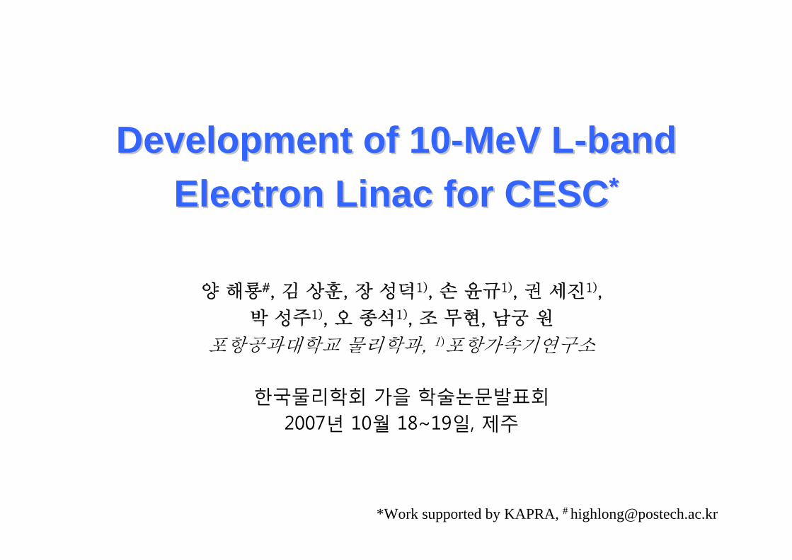
Development of 10Development of 10--MeV LMeV L--bandbandElectron Electron LinacLinac for CESCfor CESC**
*Work supported by KAPRA, # [email protected]
양 해룡#, 김 상훈, 장 성덕1), 손 윤규1), 권 세진1),
박 성주1), 오 종석1), 조 무현, 남궁 원
포항공과대학교 물리학과, 1)포항가속기연구소
한국물리학회 가을 학술논문발표회2007년 10월 18~19일, 제주

2/21한국물리학회 가을 학술논문발표회, 2007년 10월 18~19일, 제주
IntroductionIntroduction
• L-band traveling-wave electron linac
• Irradiation applications
• 10 MeV and average 30 kW
• Single klystron (pulsed 25 MW)
• Single accelerating column
• Vertical mount

3/21한국물리학회 가을 학술논문발표회, 2007년 10월 18~19일, 제주
Accelerator ParametersAccelerator Parameters
- 2.3 MeV/°CTemperature Shift Factor
- 4.7 MeV/ABeam Loading Factor
4.2 MV/mAverage Accelerating Gradients
40°C ± 1°COperating Temperature
0.8 μsRF Filling Time
2π/3 modeOperating Mode
Disk-loadedShape of Cell
Constant-impedance
Type of Structure
Accelerating Structure Parameter
35 kWAverage Beam Power
90%Beam Transmission Rate
1.4 APulsed Beam Current
10.7 MeVBeam Energy
Beam Parameter
6 μsPulse Length
1.6 APulsed Beam Current
80 kVHigh Voltage
E-gun Parameter
60 kWAverage RF Power
350 HzRepetition Rate
7 μsPulse Length
25 MWPulsed RF Power
1.3 GHzOperating Frequency
RF System Parameter
4/21한국물리학회 가을 학술논문발표회, 2007년 10월 18~19일, 제주
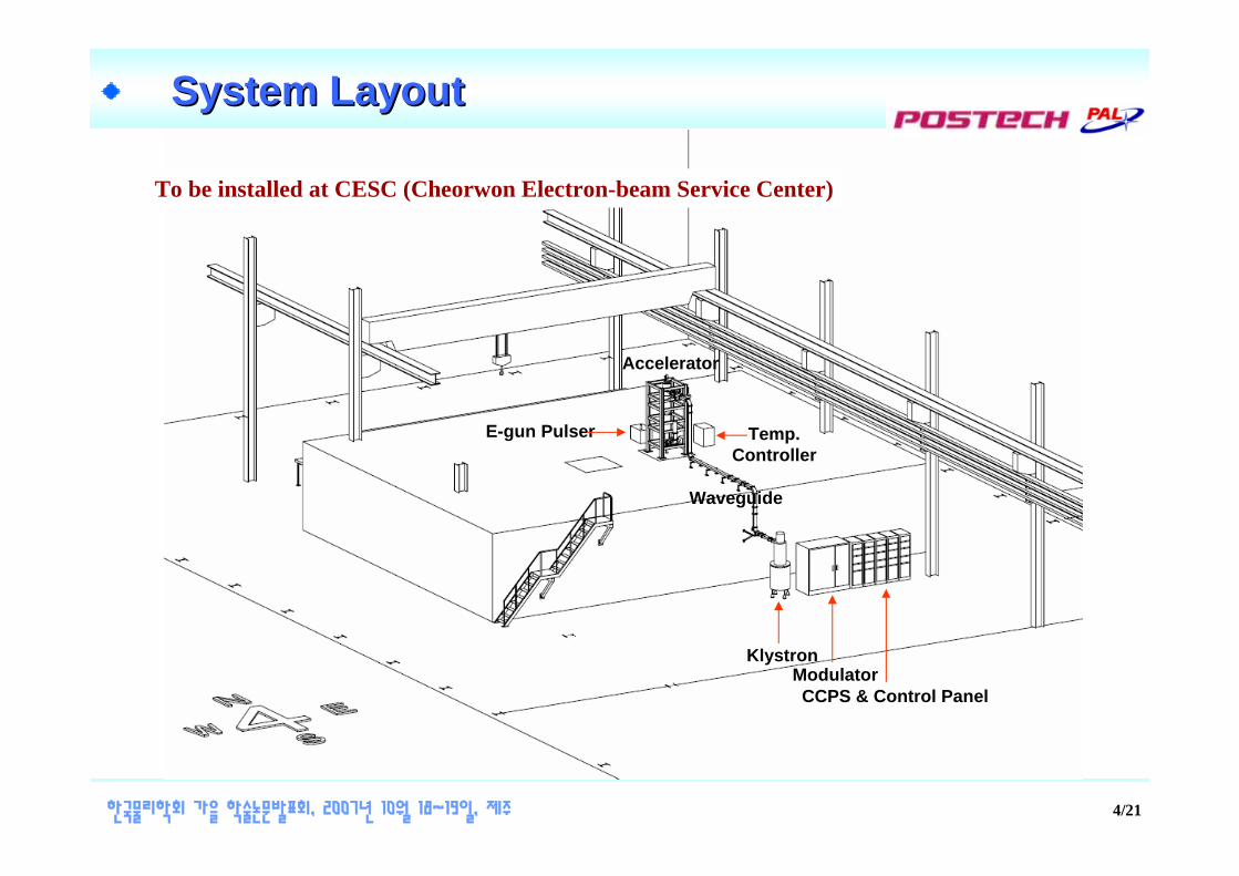
System LayoutSystem Layout
KlystronModulatorCCPS & Control Panel
Accelerator
Waveguide
E-gun Pulser Temp.Controller
To be installed at CESC (Cheorwon Electron-beam Service Center)

5/21한국물리학회 가을 학술논문발표회, 2007년 10월 18~19일, 제주
PB: Pre-buncher IP: Ion PumpPGV: Pneumatic Gate Valve PS: Phase ShifterATT: Attenuator BEM: Beam Energy MonitorBCM: Beam Current Monitor
Accelerating Column
ATT
Solenoid Magnet PS
Load
Modulator
PS
E-Gun
PGV
BEM
PB BCM
IP
IPIP
PGV
IP Controller
E-gun Heater PS
E-gun HV Pulser RF Window RF Window
Klystron
Vacuum GaugeController
Cooling WaterDistributor
TemperatureController
Source RF Generator
Master Trigger
Vacuum GaugeController
Steering Coil Controller
IP ControllerBeam Diagnostics
System
Cooling Stand
Inverter
Schematic Diagram of Schematic Diagram of LinacLinac SystemSystem
Beam Scanner

6/21한국물리학회 가을 학술논문발표회, 2007년 10월 18~19일, 제주
Beamline ConfigurationBeamline ConfigurationE-gun PGV
Pre-buncherSteering coil
SolenoidsMagnets
Accelerating Column
BCM
RF WindowVacuum System
Waterload
PGV The beam scanner system is followed by this drift tube.
Iron-wrappedSolednoids
Magnet

7/21한국물리학회 가을 학술논문발표회, 2007년 10월 18~19일, 제주
Accelerating ColumnAccelerating Column
Bunching Section
Normal Section
0.06231.00Normal
0.04150.985th buncher
0.04310.924th buncher
0.04420.883rd buncher
0.04890.752nd buncher
0.05380.651st buncher
Attenuation Coefficient
(Nep/m)
Phase velocity / cCell
Cell Characteristics
-5
-4
-3
-2
-1
0
1
2
3
4
5
0 5 10 15 20 25 30
Cavity Cell Number
RF
Phas
e D
evia
tion
(deg
.)
Phase shift for cavity cellCumulative phase shift for per cell relative to No.0

8/21한국물리학회 가을 학술논문발표회, 2007년 10월 18~19일, 제주
RF CouplersRF Couplers
Shorting bar
Tapered W/G
W/G to Coax adapter Network analyzer
(Agilent E8362B)
1 2
)( 2/2 πωz
)( 3/22 πωz
)(2 mz ω)(1 ωz
)( 2/πωϕ
)( 3/2πωϕ
)( mωϕ
2/)( 3/22/ ππ ωωω +=m
Measurement Setup(Khyl’s mothod on TRwave coupler)
Impedance Smith-chart
-120.6°-119.9°
179.4°179.2°
117.7°120.1°
Output couplerInput coupler
)( 2/πωϕ)( mωϕ
)( 3/2πωϕ

9/21한국물리학회 가을 학술논문발표회, 2007년 10월 18~19일, 제주
Focusing SolenoidsFocusing Solenoids
32440005
32440004
32360003
32320002
3.620001
Current (A)
Ampere-turn
Solenoids
1 2 3 4 5
Solenoids Characteristics
Powered by single DC power supply
0 50 100 150 200 250 3000
250
500
750
1000
1250
1500
Long
itudi
nal M
agne
tic F
ield
(G)
Longitudinal Distance (cm)
Longitudial B-filed

10/21한국물리학회 가을 학술논문발표회, 2007년 10월 18~19일, 제주
Waveguide Network with Coax LineWaveguide Network with Coax Line
e-Beam
KlystronOutput W/G
RF power25 MW-pulsed60 kW-average
High-power W/G Load
W/GStraight Section
W/GE-bend
W/GE-bend
VariableΦ-Shifter
W/G-D/C70 dB
W/GE-bend
Low loss Dielectric Coaxial Cable ( ~4 m long)
Pre-buncher
e-Gun
L-bandAccelerating
Column[IHEP in China]
W/G-D/C70 dB
Arc Sensing
View Port
L-band Waveguide Network
VariableAttenuator
W/GVacuum
Pumping port
Components inside the red boxes are filled with SF6 gas.
W/GVacuum
Pumping port
RF Window[Thales]
RF Window[Thales]
W/GStraight Section
W/GGas Feeding Port
Arc Sensing
View Port
W/GGas Feeding Port
Coax. D/C~53 dB
W/G-D/C 70 dB
W/GStraight Section
Arc Sensing
View Port
Components inside the blue boxes are operated under vacuum. W/G
CX-DC38 dB
W/G-CoaxConverter
Low- powerW/G Load

11/21한국물리학회 가을 학술논문발표회, 2007년 10월 18~19일, 제주
Klystron Klystron
1.7 μPervPerveance
28 V / 25 AHeater
230 ABeam current
264 kVCathode voltage
7 usRF pulse duration
300 WPeak drive power
60 kWRF output average power
30 MWRF output peak power
1.3 GHzFrequency
SpecificationsThales TV2022D Tube
1 : 13 Pulse Transformer
12/21한국물리학회 가을 학술논문발표회, 2007년 10월 18~19일, 제주
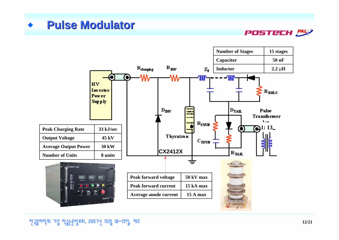
Pulse ModulatorPulse Modulator
CX2412X
15 A maxAverage anode current
15 kA maxPeak forward current
50 kV maxPeak forward voltage
8 unitsNumber of Units
30 kWAverage Output Power
45 kVOutput Voltage
33 kJ/secPeak Charging Rate 1: 13
2.2 μHInductor
50 nFCapacitor
15 stagesNumber of Stages

13/21한국물리학회 가을 학술논문발표회, 2007년 10월 18~19일, 제주
HighHigh--voltage Pulse Testvoltage Pulse Test
Time (μs)0 2 4 6 8 10
247.72 kV
Load beam voltage
Load beam Current
246.4 A
12
10 HzRepetition Rate
9.3 μsPulse Width (70 %)
42 kVCharging Voltage
246.4 ALoad Current
247.72 kVLoad Voltage
1 kΩLoad Impedance
Test Result

14/21한국물리학회 가을 학술논문발표회, 2007년 10월 18~19일, 제주
S
Control SystemControl System
E-gun HV Pulser
IP Controller
Vacuum GuageController
BCM
W/G Power Detector - 1F, 2, 3
Remote PC
Modulator Control
Cooling waterControl
Conveyor beltControl
Radiation & Protection
Control
Main
Control
ControlInterlockMonitoring
F
F
F
S
S
S
S
S
S
S
F
RS485
S
Solenoid Magnet PS
Steering Coil PS
Arc Detector- 1, 2, 3
W/G Power Detector - 1R
PGV - 1,2
PGV ControllerF
F
E-gun Heater PS
MasterTrigger
F
AcceleratorControl

15/21한국물리학회 가을 학술논문발표회, 2007년 10월 18~19일, 제주
Beam Commissioning ScenarioBeam Commissioning Scenario
89%Obtain the optimum condition
by the commissioningof the pre-buncher.
on1.625 MWononOperationCondition7.
77%Raise the input power until
the output beam energyat the operation condition.
off1.6to 25 MWononNominal
RF Power6.
86%Raise the input currentat the operation condition.offto 1.612 MWonon
NominalCurrent5.
85%Raise the input power
Until the outputbeam energy is 10 MeV.
off0.1to 12 MWononRF On4.
100%Turn on the solenoids.
Adjust the steering coil refer tothe simulation result.
off0.1offonre-adjustSolenoids
On3.
87%Search the max. transmissioncondition of the steering coils.
Find the offset rate.off0.1offoffonAlignment
Check2.
Check the outputbeam current.off0.1offoffoff
InitialCondition1.
Goal(transmission)RemarksPre-
buncher
InputCurrent
(A)
Input RF Power
(into acc.)SolenoidsSteering
CoilsStep

16/21한국물리학회 가을 학술논문발표회, 2007년 10월 18~19일, 제주
Beam Commissioning Beam Commissioning –– Alignment CheckAlignment Check
1˚misalignment no output beam
Initial condition: no power, no solenoid, no pre-bunching,operation the E-gun emitting 0.1 A only
Steering coils find the value of the misalignment
0
0.1
0.2
0.3
0.4
0.5
0.6
0.7
0.8
0.9
1
0 0.2 0.4 0.6 0.8 1Misalignment angle (deg.)
Tran
smis
sion
rate
Input beam current: 0.1 A
0
0.1
0.2
0.3
0.4
0.5
0.6
0.7
0.8
0.9
1
0 0.2 0.4 0.6 0.8 1
R-direction E-gun position offset (cm)
Tran
smis
sion
rate
Input beam current: 0.1 A

17/21한국물리학회 가을 학술논문발표회, 2007년 10월 18~19일, 제주
- 2
- 1 .5
- 1
- 0 .5
0
0 .5
1
1 .5
2
0 5 0 1 0 0 1 5 0 2 0 0 2 5 0 3 0 0 3 5 0L o n g i t u d in a l p o s i t io n ( c m )
x, y
pos
ition
(cm
)
x m e a nx 9 9 %x 1 %y m e a ny 9 9 %y 1 %
- 2
- 1 .5
- 1
- 0 .5
0
0 .5
1
1 .5
2
0 5 0 1 0 0 1 5 0 2 0 0 2 5 0 3 0 0 3 5 0L o n g i t u d in a l p o s i t io n ( c m )
x, y
pos
ition
(cm
)
x m e a nx 9 9 %x 1 %y m e a ny 9 9 %y 1 %
Beam Commissioning Beam Commissioning –– Solenoids OnSolenoids On
Focusing by solenoids 100% transmission
1° misalignment, solenoils on
Re-adjusted by steering coils
Re-adjusted by steering coils refer to simulation result
Beam Size
Beam Size
Optimum condition

18/21한국물리학회 가을 학술논문발표회, 2007년 10월 18~19일, 제주
0.7
0.75
0.8
0.85
0.9
0.95
1
0 5 10 15 20 25
Input Power (MW)
Tran
smis
sion
0
2
4
6
8
10
12
14
16
18
Ener
gy (M
eV)
TransmissionEnergy (MeV)
Input beam current: 0.1 A
Beam Commissioning Beam Commissioning –– RF OnRF On
Raise the RF power at 12 MW: Beam energy limited by 10 MeV due to neutron production

19/21한국물리학회 가을 학술논문발표회, 2007년 10월 18~19일, 제주
0.7
0.75
0.8
0.85
0.9
12 15 18 21 24 27 30Input Power (MW)
Tran
smis
sion
rate
0
4
8
12
16
Ener
gy (M
eV)
TransmissionEnergy (MeV)
Input current: 1.6 A
Beam Commissioning Beam Commissioning –– Nominal ConditionNominal Condition
Raise the input current to nominal value: 1.6 A
Raise the RF power to nominal value: 25 MW
0.8
0.82
0.84
0.86
0.88
0.9
0 0.4 0.8 1.2 1.6 2Input Current (A)
Tran
smis
sion
rate
0
2
4
6
8
10
Ener
gy (M
eV)
TransmissionEnergy (MeV)
Input RF power: 12 MW
nominal value
nominal value

20/21한국물리학회 가을 학술논문발표회, 2007년 10월 18~19일, 제주
Beam Commissioning Beam Commissioning –– Operation ConditionOperation Condition
Scanning the transmission rate during change the pre-buncher phase
Pre-buncher optimizing ΔφPB 10˚, transmission 90%, 10.7 MeV
0
2
4
6
8
10
12
14
16
0 60 120 180 240 300 360Phase difference (˚)
Ener
gy (M
eV),
Pow
er (M
W)
0
0.2
0.4
0.6
0.8
1
Tran
smis
sion
rate
Energy (25MW, 1.6A)Power (25MW, 1.6A)Transmission rate
Input current: 1.6 APre-buncher input power: 3.75kW
max. power point

21/21한국물리학회 가을 학술논문발표회, 2007년 10월 18~19일, 제주
Current Status and PlanCurrent Status and Plan
Klystron & Modulator• Fabrication and Assembling finished.• PFN to be tuned for the flat-top requirement.• Installed at the CESC site.
Waveguide and Coaxial-line • Ready to installation.
Accelerating Column• Delivered to Pohang.• Beamline also to be assembled.
Under Development• Beam Scanner• Cooling System• Control System
Commissiong is planned this year.


![100MeV Linac design.ppt [호환 모드] - POSTECHpsl.postech.ac.kr/material/seminar/070528_100MeV_Linac... · 2007-06-01 · PEFP 100 MeV 선형가속기 50 keV DTL(2) DTL(1) RFQ](https://img.dokumen.tips/doc/110x75/5f318c813d475e37843c3c84/100mev-linac-eeoe-postechpslpostechackrmaterialseminar070528100mevlinac.jpg)