Embed Size (px)
Citation preview
Development Environment for Fluid-Power-Mechatronic Systems
Frank Engler
EPLAN Software & Service GmbH & Co. KG, An der alten Ziegelei 2, 40789 Monheim
Heiko Baum
FLUIDON GmbH, Jülicher Straße 336, 52070 Aachen
René von Dombrowski
FLUIDON GmbH, Jülicher Straße 336, 52070 Aachen
ABSTRACT
Fluid-power-mechatronic systems are characterized by close networking among all the
participating technical disciplines and through complex interactions between the subsystems
required to attain the overall functionality. In view of this close interconnectedness of the
development disciplines and the variety of companies involved as well as the resulting complex
process structures, the development process for fluid-power-mechatronic systems is becoming
increasingly difficult and the elimination of inadequacies in the product reliability is often realized
using iterative problem solutions at a much later moment in the development process.
Within the "Fluidtronic" joint project, which is funded by the German Federal Ministry of
Education and Research, work is therefore being carried out by a consortium consisting of nine
industrial companies and two research institutes on the creation of an adapted development
environment in the form of a PLM solution. The handling of data and information as well as the
integration of simulation tools within this PLM concept form the core of this article.
The EPLAN documentation tool functions as the information bearer, for both technical and
commercial data in the presented concept. Here the planning and documentation of the fluid-
power-mechatronic system is carried out on the basis of schematics for the overall system as
well as for any subsystems. All the component specifications are stored with the items. Thus, not
only the technical data, such as the geometric dimensions or the performance characteristics,
but also the commercial information, such as the part numbers or order information, is
7th International Fluid Power Conference Aachen 2010
1

contained. Thanks to a direct link to the manufacturer databases, the current item information is
always available on this level.
From the schematics, in turn, all the relevant documents for a complete system design are
generated automatically. In addition to order lists and bills of materials, these are documents
such as maintenance schedules, lubrication lists or piping diagrams. All the schematics, item
formation and designing documents are interconnected dynamically, so that inconsistencies in
the database are avoided and changes within the plant planning are implemented consistently in
the complete documentation structure without the user having to lift a finger.
The simulation level is located under the level of the product information. This level contains
simulation tools that allow the designing engineer to carry out simulation-supported calculations
and to analyze the effects of different system configurations. Thus allowing simulations in any
detail desired to be derived from the system schematics, from simple logical interconnection
tests up to complex dynamic examinations of the system behavior. Simply by marking the
relevant system or partial system both the model structure and the current item parameters are
transferred directly into a simulation model. In turn, calculation results from the simulation flow
back into the documentation in the form of dimensioning and design proofs. Linking between the
simulation level and the product information level is also carried out dynamically so that changes
in the system structure or in the components used are implemented directly within the simulation
environment. Since building up the structure and the parameterization as a rule represent about
50% of the work required for simulation projects, a huge reduction in time can be achieved here
in addition to advantage of a consistent database.
All the companies involved in the development process use the same database. The entire
development process is thus optimized by means of an intelligent access rights management
and orientation to reference processes.
7th International Fluid Power Conference Aachen 2010
2

1 INTRODUCTION
The development of increasingly powerful technical systems results in a constantly
increasing product complexity and and increasing functional scope. Modern fluid-power-
mechatronic systems unify partial systems from various specialized disciplines such as
hydraulics, pneumatics, electrical engineering, mechanical engineering, informatics or
control technology. These very heterogeneous systems have to cooperate increasingly
closely and communicate more effectively than ever with each other in order to ensure
the functionality of the overall system.
Fluid-power-mechatronic applications are nowadays used by all fields of industry, with
these often being highly specialized individual developments that are manufactured on
the basis of specific customer requirements and in small batch sizes. Not only is the
correct coordination and synchronization of all the components as well as their
properties required in order for these plants to run reliably, but also efficient cooperation
of the participating companies is also indispensable. However these requirements were
not included sufficiently in the development processes in the past. Due to a lack of
networking and synchronization during the development, for example, functional
problems that are only discovered at a late point in the development process arise when
different partial systems are combined. In addition, unstructured information flows mean
that the derivation of requirements for individual components on the basis of the
specified constraints of the overall system is only possible through using experience
from previous projects. This applies in particular to incompatibilities regarding material
and system that are not recognized at an early stage in the development process and
whose late discovery requires a cost-intensive, iterative procedure in order to eliminate
the problem. /Mue08/
A large optimization potential lies in the support through simulation software that has not
been exploited sufficiently in the past. Fluid-power-mechatronic simulation programs are
often not during during the development process, but are only used in those cases in
which designing based on experience is insufficient or when malfunctions occur when
the plant is in operation. Insufficient integration of fluid-power simulation tools in the
development process complicates understanding of the overall system in the early
7th International Fluid Power Conference Aachen 2010
3

development phases and makes later commissioning of the plants increasingly tedious.
/Mur09/
2 PRESENTATION OF THE FLUIDTRONIC JOINT PROJECT
In the course of the research project a hydraulic forging press was used as a reference
application of a fluid-power-mechatronic system. In its complex structure it unites a wide
variety of partial systems from the technical disciplines of hydraulics, mechanical
engineering and electronics as well as control technology. Its large dimensions in
particular mean that all the partial systems do not liaison until the actual plant
commissioning. Since the plant dimensions mean that this has to be carried out at the
customer, the customer notices all these inaccuracies and malfunctions in the
interactions of the partial systems during commissioning. In addition, finding faults at this
late moment in the development involves a large amount of time and high costs.
The aim of the "Fluidtronic" joint project is therefore the early identification of inherent
system risks and the ensuring of reliable commissioning and plant functioning for the
duration of the entire product lifecycle. This is only possible if the cooperation between
the concerned specialist disciplines and companies is synchronized and integrated
better with the aim of efficient product development.
For this reason the development of a fluid-power-mechatronic system requires a cross-
company platform that is called the development environment. Figure 1 shows the
operative coupling between the elements considered in the project in an integrated
development environment for fluid-power-mechatronic systems.
7th International Fluid Power Conference Aachen 2010
4

Figure 1: Integrated fluid-power-mechatronic development environment
The development environment encompasses all the disciplines and activities within the
product development process as well as the methods, tools and IT systems used in it. In
addition, it contains both the associated product and process information from the
system concept through to the commissioning as well as the feedback of the operating
data during the product lifecycle.
3 CONTINUOUS ENGINEERING
An important point for optimizing the development processes is used by the continuous
usage of software support. The development and implementation of new software
models and methods transforms the conventional development process into a computer-
aided product development that makes it possible to carry out virtual plant design and
virtual commissioning at a very early stage.
7th International Fluid Power Conference Aachen 2010
5

In the course of the Fluidtronic project concepts were implemented – using the two
development tools "EPLAN" and "DSHplus" (Figure 2) – that link the project designing
and documentation with the dimensioning of new systems and thus exploiting synergies.
Figure 2: Coupling principle DSHplus – EPLAN
Modern documentation programs such as EPLAN can already replace the still prevalent
purely drawing programs for creating schematics and offer integrated possibilities for
designing new plants. The user places and dimensions the components of his system
symbol-based and ISO-conform on the schematic by dragging-and-dropping. The
connections of the items between each other can in turn have specific properties
assigned to them and be evaluated.
At the same time as the drawing is created, the bills of materials and order lists are
created automatically with all the item identifiers, item sizes and part numbers. However,
report pages, such as maintenance lists, lubrication lists or pipe connection lists, are
also determined immediately from the created schematics. All the documents required
7th International Fluid Power Conference Aachen 2010
6

for designing and documentation are interlinked dynamically so that a uniform database
is provided and errors as well as inconsistencies can be avoided.
At this point, however, the continuity of the development chain was at an end. For was
there any possibility of examining the designed system for plausibility or even optimizing
them with regard to increasing the performance or inefficiency?
In the classical development process, static system design by hand or dimensioning of
the items on the basis of experience was carried out – if at all. Only if extreme pressure
pulsations or vibration problems occurred during running plant operation and this
resulted in a functional impairment or even standstill of the plant, was dynamic
simulation brought into play in order to master the problem and conceive suitable
remedies. The consistent use of simulations on the one hand allows future weak points
of the system to already be recognized and eliminated at a very early point in the
development process while on the other hand the consistent use of software allows
further optimization potentials, such as reductions in costs and time, but also increases
in efficiency and performance, to be tapped.
Coupling of the documentation and simulation represents the link missing up to now.
The hydraulic schemes are transferred at the click of a button from EPLAN to the
DSHplus system simulation. In addition to the system schematic or the desired sub-
system structure, the simulation program automatically imports all the parameters of the
designed components from the engineering structure through the link to the component
database — and when changes take place in the documentation these are also imported
immediately into the simulation model by the dynamic linking of the two development
tools without the user having to do anything. The interconnection of the documentation
and simulation thus ensures a uniform database, and the latest component information
is always available to the simulation models as parameter inputs. The results of the
dynamic system simulation as well as important system and environment parameters of
the system and the constraints of the system are made available as an HTML report.
This report can in turn be linked dynamically with the original design schematic and thus
completes the documentation of the plant with design and dimensioning reports as
certitude for the customer. /Bau07/
7th International Fluid Power Conference Aachen 2010
7

The range of possible applications of the new networking is almost unlimited and ranges
from simple logical circuiting checks of the hydraulic or pneumatic drives through the
item dimensioning, to the design of fluid-power-mechatronic systems and up to system
optimization with regard to performance, reliability or efficiency of the plant by means of
dynamic simulation.
Through the use of the interfaces available in DSHplus for the coupled PLC simulation
or hardware-in-the-loop simulation, this consistent engineering concept can additionally
be extended by the virtual commissioning of the reference system with a real control
device in the further course.
4 PROCESS STEPS OF THE DEVELOPMENT
Figure 3 shows the various phases of the development process of a fluid-power-
mechatronic system.
Figure 3: Phase structure of the development process
Starting from the initial sales-supporting feasibility analysis in the offer phase, the
system structure is planned in ever increasing detail trough rough concepting in Phase 2
to the final product structure in Phase 3. In Phase 4 commissioning of the plant is then
carried out, which can optionally be analyzed and optimized using condition monitoring
strategies in Phase 5 across the entire product lifecycle.
7th International Fluid Power Conference Aachen 2010
8

Optimization of the various phases using a software-aided development environment is
shown in Figure 4 and explained in more detail below.
Figure 4: Support of the development processes by means of software tools
The emphasis of the explanations lies on the cooperation between the OEM and the
supplier in Phase 3. A noted acceleration of and increase in the quality of the
development process can be achieved through a PLM-aided process of exchanging the
design documents.
4.1 Phase 1: Information acquisition in Sales
In initial meetings with the customer, Sales records the required data, for example on
the basis of an Excel template. The parameters required for a feasibility study are
entered in this template on the basis of the customer requirements. An example of the
structure of such a template is shown in Figure 5. The parameters to be recorded are
divided roughly into basic components of the plant to be designed.
On the basis of individual parameters to be specified by the customer it is then possible
to derive further parameters required to design a press. An initial feasibility study of the
customer requirements for the press can be carried out by Sales in the background on
the basis of these data. In the process a comparison with the parameters of projects that
7th International Fluid Power Conference Aachen 2010
9

have already been realized is used to identify commonalities of the requirements and to
point out such realized projects. The listing of these projects allows Sales to make a
rapid statement on the feasibility to the customer.
Figure 5: Template for parameters of the key point plan
If there is no similar project, a standard template is suggested to Sales, consisting
respectively of two documentation and simulation projects attuned to each other, that
can then be elaborated in detail by the developers in the back office. It may be possible
to already present existing simulation results or ones generated by the back office at this
stage. The feasibility study is used as the basis for the contract negotiations with the
customer.
4.2 Phase 2: Rough designing by the OEM
After the conclusion of the contract negotiations, the used template consisting of the
design template and simulation model is detailed further. The task of the experts is now
to optimize the interaction of the components further so that the performance assured in
the specifications are fulfilled. With the exception of individual specified parameters
which the OEM may not modify according to the contract, the experts have the option to
7th International Fluid Power Conference Aachen 2010
10

modify the parameters of the components, if necessary also without consideration of any
availability of real components, and thus to improve the interaction continuously.
During the constant optimization of the interaction of the items within the system
structure, a continuous exchange takes place between the mechanical and hydraulic
sections of the company. In the process the mechanical and hydraulic constraints of the
press are localized ever further and help to form the image of the press continuously
(Figure 6).
The previously calculated or recorded item parameters are entered by clicking the
symbols. Since the customer does not know all the parameters at this stage, individual
parameters have to be assumed and stored at the components.
Figure 6: Design-oriented component of the development template
After all the calculated and recorded parameters have been entered, the system
structure as well as the component data of the design schematic are passed on to the
simulation model matching the template (see Figure 7) so that an initial simulation of the
7th International Fluid Power Conference Aachen 2010
11

interaction of the individual parameters is carried out. In the process several result
diagrams are created from which the feasibility of the requirements can be read.
The recorded parameters are not always sufficient in order to make a definitive
statement on the feasibility. Often the requirements also run in a threshold region so that
robust conclusions on the feasibility are not possible on the basis of the existing
information. In this case iterative loops between Sales and the experts of the company
are used to improve the information situation further. It is now possible for the expert to
adapt and set the constraints more precisely and in more detail.
The simulation environment allows a report to be created and the calculation results to
be stored after the simulation of the interaction. The report and its conclusion on the
feasibility make it possible for Sales to avoid making promises to the customer that can
result in enormous additional efforts in the further course of the press design. The
simulation results furthermore serve as a reference for the subsequent detailed planning
at the suppliers and form the basis for the beginning of detailed planning in Phase 3.
Figure 7: Simulation component of the development template
7th International Fluid Power Conference Aachen 2010
12

4.3 Phase 3: Planning of plant details by the suppliers
During Phase 2 the OEM determined the required dynamic properties of the modules of
the hydraulic press using simulations in DSHplus. The interaction of the component
requirements that were defined in increasing detail was improved constantly in the
process. However, not only "standard components" as they can be obtained from
various suppliers have been used in the template. Instead the hydraulically optimal
parameters are determined and defined.
In order to pass from this "rough designing" to the real system design, the schematic,
which still highly simplified, now has to be planned in detail with regard to its real
feasibility. Individual systems, such as the pump, still stand as a summarization for
complete subsystems whose exact structure still have to be defined. Figure 8 illustrates
this schematically using geometric figures.
Figure 8: Interaction between DSHplus and EPLAN
Within the EPLAN design level it is now possible to store design information at the
individual symbols. However the suppliers first have to carry out detailing of the modules
into subsystems that can really be realized. To this purpose the design document is
made available to all the suppliers within the development environment by using the
PLM system.
In order to ensure know-how protection during exchanging of the design data, the
modules that do not have to be detailed by a specific supplier can be transferred
combined in a type of "overall blackbox" (Figure 9). Only the module that is to be
detailed by the supplier is left editable.
7th International Fluid Power Conference Aachen 2010
13

Figure 9: "Black-box logic" for passing on to suppliers
The EPLAN document as well as the modified DSHplus schematic including the
reference result is transferred to the supplier in a suitable form. The supplier now has all
the relevant constraints of the overall system and requirements placed on the module to
be detailed.
The supplier forms and details the initially simply conceived subsystem that he wants to
offer to the OEM in EPLAN. In the process he builds up the interconnecting logic of the
individual components into a subsystem in the engineering software, as sketched in
Figure 10.
Figure 10: Detailing of subsystems by suppliers
7th International Fluid Power Conference Aachen 2010
14

In the process the supplier can use his company-specific database in which the
components including their engineering and simulation data are stored.
The supplier subsequently transfers the engineering schematic into a simulation model.
The simulation parameters are in turn imported automatically from the documentation.
The supplier can now directly test the effects of the use of various components within
the plant engineering in the DSHplus simulation, compare them with the reference result
and thus find the optimal solution.
As soon as an optimal solution has been found, the design information is added to the
documentation and returned to the OEM via the PLM system (Figure 11). This process
is repeated in the interaction between the OEM and all the (system) suppliers.
Figure 11: Combining of the supplier information by the OEM
The OEM subsequently combines the detailed partial engineering schematic into an
overall document that automatically also contains all the parameters relevant for the
simulation.
The OEM in turn now transfers the overall schematic with all the detailed work into the
simulation model in order to validate the components and modules now available in real.
Unforeseeable interactions between supplier modules can be recognized in the detail
simulation of the overall system at an early stage of the development process and
remedial measures taken. If the OEM has recognized potential weak points or causes of
faults, he contacts the individual suppliers with this knowledge and requires
modifications of the corresponding subsystems.
7th International Fluid Power Conference Aachen 2010
15
Thanks to this more direct and more efficient cooperation as well as the multiple iterative
loops between the customer, the OEM and the suppliers within the simulation
environment, it is possible to design more reliable and more robust machines in shorter
times. /Mue08/
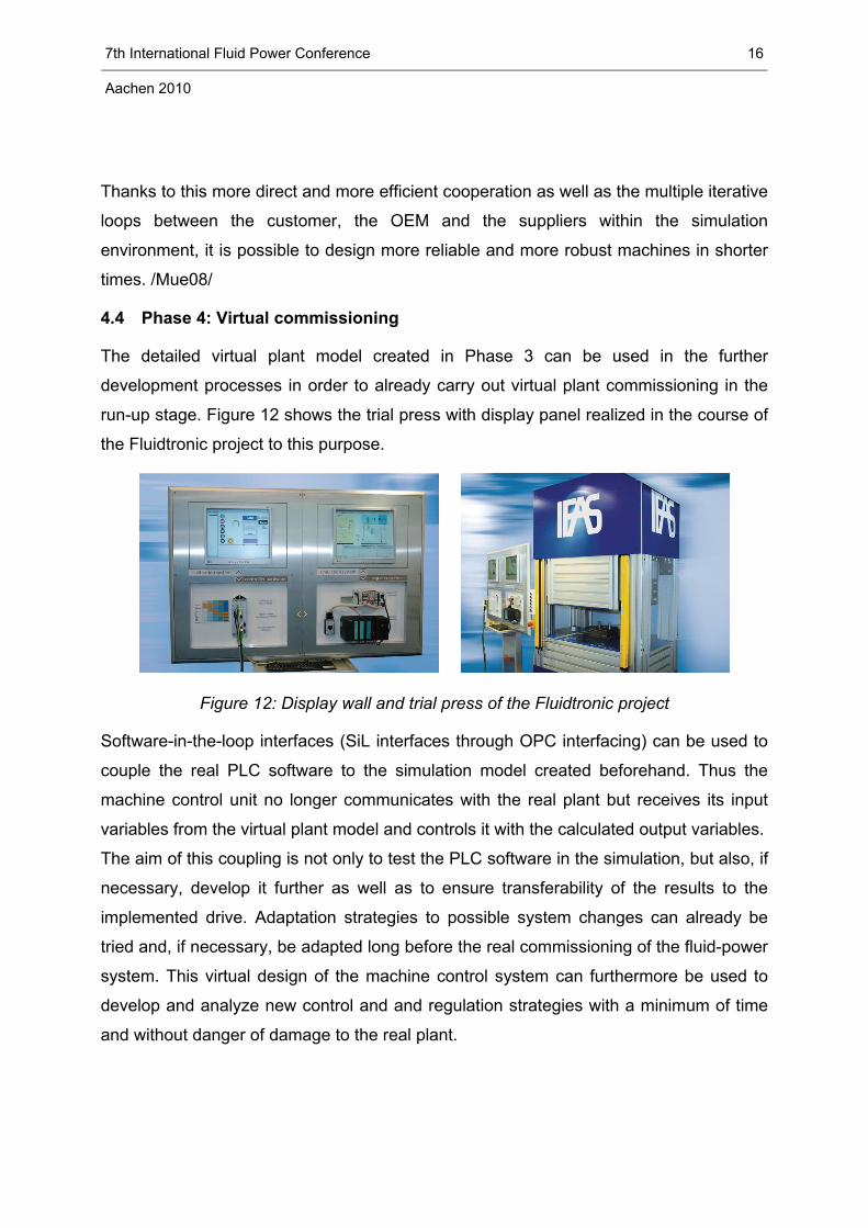
4.4 Phase 4: Virtual commissioning
The detailed virtual plant model created in Phase 3 can be used in the further
development processes in order to already carry out virtual plant commissioning in the
run-up stage. Figure 12 shows the trial press with display panel realized in the course of
the Fluidtronic project to this purpose.
Figure 12: Display wall and trial press of the Fluidtronic project
Software-in-the-loop interfaces (SiL interfaces through OPC interfacing) can be used to
couple the real PLC software to the simulation model created beforehand. Thus the
machine control unit no longer communicates with the real plant but receives its input
variables from the virtual plant model and controls it with the calculated output variables.
The aim of this coupling is not only to test the PLC software in the simulation, but also, if
necessary, develop it further as well as to ensure transferability of the results to the
implemented drive. Adaptation strategies to possible system changes can already be
tried and, if necessary, be adapted long before the real commissioning of the fluid-power
system. This virtual design of the machine control system can furthermore be used to
develop and analyze new control and and regulation strategies with a minimum of time
and without danger of damage to the real plant.
7th International Fluid Power Conference Aachen 2010
16

A further reduction of the development and commissioning time is provided by the
Hardware-in-the-Loop (HiL) simulation. By coupling the real PLC hardware to the system
simulation the real control hardware can already be conditioned optimally in advance.
Starting from a host PC on which the simulation model is calculated, connection is
carried out via a fieldbus card that has input and output modules (signal converters).
The signals from the model are converted in to real signals and are read in, processed
and subsequently returned as actuation and control signals to the simulation by the
controller hardware. A special software module carries out the data exchange between
the fieldbus coupler and the simulation model. Virtual commissioning of the real PLC
hardware thus allows cable errors within the enclosures to be discovered in advance,
limit queries to be calibrated and various operating and error scenarios to be run
through. /Ket08/
4.5 Phase 5: Condition monitoring
Further usage options for the virtual plant model lie in plant monitoring during ongoing
operation. By coupling the virtual model to real operating data the simulation model can
be used as a monitoring unit and interpret deviations between the simulation model and
the real plant using previously defined algorithms in order to predict, for example,
component wear.
CONCLUSION
In view of the high complexity during the conception, the development and the
commissioning of fluid-power-mechatronic plants the current conventional development
process manifest clear deficits. The presented development environment overcomes
these deficits through an optimization of the development processes as well as the
consistent use throughout the development of engineering and simulation software.
The structured interaction and cooperation of all the companies involved in the
development process and the supply to these of detailed system information and up-to-
date data results in the acceleration of the development processes under simultaneous
optimization of the overall system.
The presented results were elaborated in the course of the Fluidtronic research project
that is funded by the German Federal Ministry of Education and Research in the
7th International Fluid Power Conference Aachen 2010
17

"Research for Future Production" framework concept and is managed by the PTKA in
Karlsruhe as the project manager.
REFERENCES
/Mue08/ G. Schuh, J. Müller, C. Nussbaum, Fluidtronic - Entwicklungsumgebung
für fluidtechnisch-mechatronische Systeme, Tagungsband 6.
Gemeinsames Kolloquium Konstruktionstechnik, Aachen 2008
/Mur09/ H. Murrenhoff, R. von Dombrowski, T. Verkoyen, Fluidtronic -
Entwicklungsumgebung für fluidtechnisch-mechatronische Systeme, wt
Werkstattstechnik online Jahrgang 01/2009
/Bau07/ H. Baum, R. von Dombrowski, G. Birmes, Durchgängiges Engineering
im Bereich der Fluidtechnik - Konstruktions-Workflow durch direkte
Kopplung von Dokumentation und Simulation, O+P Zeitschrift für
Fluidtechnik, 08/2007
/Ket08/ R. Kett, Virtuelle Inbetriebnahme von Reglern und Steuergeräten,
Tagungsband zum 5. Kolloquium Mobilhydraulik, Karlsruhe 2008
7th International Fluid Power Conference Aachen 2010
18