Embed Size (px)
Citation preview

Hornsby Shire Council
ABN 20 706 996 972 PO Box 37, Hornsby NSW 1630 Phone 02 9847 6666 Email [email protected]
296 Peats Ferry Rd, Hornsby 2077 Fax 02 9847 6999 Web hornsby.nsw.gov.au
DEVELOPMENT DESIGN SPECIFICATION 0041
GEOMETRIC ROAD LAYOUT
© AUS-SPEC (Oct 11) July 2016

0041 Geometric Road Layout
Hornsby Shire Council
ABN 20 706 996 972 PO Box 37, Hornsby NSW 1630 Phone 02 9847 6666 Email [email protected]
296 Peats Ferry Rd, Hornsby 2077 Fax 02 9847 6999 Web hornsby.nsw.gov.au
SPECIFICATION 0041 – GEOMETRIC ROAD LAYOUT
CLAUSE CONTENTS PAGE
GENERAL ............................................................................................................................................................ 1
1.1 RESPONSIBILITIES ............................................................................................................................. 1
1.2 CROSS REFERENCES ........................................................................................................................ 1
1.3 REFERENCED DOCUMENTS ............................................................................................................. 1
1.4 STANDARDS ........................................................................................................................................ 2
1.5 INTERPRETATIONS ............................................................................................................................ 2
1.6 HIERARCHICAL ROAD NETWORK (RESIDENTIAL & INDUSTRIAL SUB-DIVISIONS) ................... 4
1.7 HIERARCHICAL ROAD NETWORK (TOWN CENTRE DEVELOPMENT) ........................................ 12
GENERAL DESIGN CONSIDERATIONS ......................................................................................................... 14
2.1 CONSULTATION ................................................................................................................................ 14
2.2 PLANNING CONCEPTS ..................................................................................................................... 14
DESIGN CRITERIA ............................................................................................................................................ 15
3.1 DESIGN CONSIDERATIONS ............................................................................................................. 15
3.2 ROAD NETWORK DESIGN CRITERIA .............................................................................................. 15
3.3 DESIGN SPEED ................................................................................................................................. 16
3.4 CROSS-SECTIONS ............................................................................................................................ 16
3.5 SIGHT DISTANCE .............................................................................................................................. 22
3.6 COORDINATION OF HORIZONTAL AND VERTICAL ALIGNMENT ................................................ 23
3.7 HORIZONTAL ALIGNMENT ............................................................................................................... 23
3.8 VERTICAL ALIGNMENT ..................................................................................................................... 25
3.9 AUXILIARY LANES ............................................................................................................................. 27
3.10 INTERSECTIONS ............................................................................................................................... 27
3.11 ROAD NETWORK ELEMENTS .......................................................................................................... 29
DOCUMENTATION ............................................................................................................................................ 31

0041 Geometric road layout
© AUS-SPEC (Oct 11) 1 HORNSBY SHIRE COUNCIL
0041 GEOMETRIC ROAD LAYOUT
1 GENERAL
1.1 RESPONSIBILITIES
Objectives General: Design and document a road system to provide the following:
- Improved urban structure and revitalisation.
- Convenient and safe access for pedestrians, vehicles and cyclists.
- Appropriate access for buses, emergency and service vehicles.
- A quality road network that minimises maintenance costs.
- A convenient zone for public utilities.
- An opportunity for street landscaping.
- Convenient parking.
- Conformance to the Disability Discrimination Act.
- An appropriate response to climate, geology and topography, existing built fabric, heritage and cultural context of the area.
- Phasing of construction to suit access and funding.
- Drainage of elements within the roadway reserve.
- Street lighting.
1.2 CROSS REFERENCES
Worksections General: Conform to 0010 Quality requirements for design.
Related worksections: The following worksections are related to this worksection:
- 0021 Site regrading.
- 0042 Pavement design.
- 0043 Subsurface drainage (Design).
- 0044 Pathways and cycleways.
- 0061 Bridges and other structures.
- 0074 Stormwater drainage (Design).
- 0075 Control of erosion and sedimentation (Design).
1.3 REFERENCED DOCUMENTS
The following documents are incorporated into this worksection by reference:
Standards AS 1348-2002 Glossary of terms - Roads and traffic engineering AS/NZS 2890 Parking facilities AS/NZS 2890.1:2004 Off-street car parking AS 2890.5-1993 On-street car parking AS/NZS 2890.6:2009 Off-street parking for people with disabilities AS/NZS 3845: 1999 Road safety barrier systems Other publications Austroads
AGRD01-2009 Guide to road design - Introduction to road design AGRD02-2006 Guide to road design - Design Considerations AGRD03-2009 Guide to road design – Geometric design AGRD04-2009 Guide to road design – Intersections and crossings AGRD04A-2009 Guide to road design – Unsignalised and Signalised Intersections AGRD04B-2009 Guide to road design - Roundabouts

0041 Geometric road layout
© AUS-SPEC (Oct 11) 2 HORNSBY SHIRE COUNCIL
AGRD06-2009 Guide to road design – Roadside design, safety and barriers AGRD06A-2009 Guide to road design – Pedestrian and cycle paths AGRD07-2008 Guide to road design - Geotechnical investigation and design
AGRD08-2009 Guide to road design - Part 8 Process and documentation
AGTM03-2009 Guide to traffic management Part 3 - Traffic studies and analysis AGTM05-2008 Guide to traffic management Part 5: Road management AGTM06-2007 Guide to traffic management Part 6: Intersections, interchanges and
crossings AGTM07-2009 Guide to traffic management Part 7: Traffic management in activity centres AGTM08-2008 Guide to traffic management Part 8: Local area traffic management AGTM11-2008 Guide to traffic management Part 11: Parking AGTM12-2009 Guide to traffic management Part 12: Traffic impacts of development AGRD08-2009 Guide to road design - Part 8 Process and documentation AP – 11.14-1999 Guide to traffic engineering practice - Bicycles AP-G34-2006 Design vehicles and turning path templates
1.4 STANDARDS
General Road design: To AGRD01 and AGRD02.
Geometric design: To AGRD03.
Intersection design: To AGRD04, AGRD04A.
Geotechnical investigation and design: To AGRD07.
1.5 INTERPRETATIONS
Abbreviations General: For the purposes of this worksection the following abbreviations apply:
- AADT: Average Annual Daily Traffic.
- ASD: Approach Sight Distance.
- AU: Auxiliary.
- BA: Basic.
- CH: Channelised.
- DDA: Disability Discrimination Act
- EDD: Extended Design Domain.
- HOV: High occupancy vehicle.
- LATM: Local Area Traffic Management.
- MGSD: Minimum gap sight distance.
- NDD: Normal Design Domain.
- SISD: Safe Intersection Sight Distance.
- DCP: Council’s Development Control Plan
Definitions General: For the purpose of this worksection, the definitions of terms used to define the components of the road reserve are in conformance with AS 1348, Glossary of Austroads Terms and AGRD03.
The words ‘street’ and ‘road’ are interchangeable throughout all parts of this worksection.
- Activity centre: Urban planning term for those places that are vibrant hubs where people shop work, meet, relax and often live.
- Approach sight distance: Relates to the ability of drivers to observe the roadway layout at an anticipated approach speed.
- Batter: Surfaces which connect carriageways or other elements of cross-sections to the natural surface. Batter provides a recovery area for errant vehicles and is used for landscaping and access for maintenance vehicles.
- Carriageway: That portion of the road or bridge devoted particularly to the use of vehicles, inclusive of shoulders and auxiliary lanes.

0041 Geometric road layout
© AUS-SPEC (Oct 11) 3 HORNSBY SHIRE COUNCIL
- Crossfall: The slope of the surface of a carriageway measured normal to the design or road centreline.
- Cycleway: Portion of a road or footpath for the exclusive use of cyclists.
- Extended Design Domain (EDD): The design domain for the assessment of existing roads. EDD is a range of values below the lower bound of the NDD.
- Footpath: A public way reserved for the movement of pedestrians and of manually propelled vehicles. The paved section of a pathway.
- Horizontal alignment: The bringing together of the straights and curves in the plan view of a carriageway. It is a series of tangents and curves that may or may not be connected by transition curves.
- Landform: The type and shape of terrain, usually including topography, geological characteristics, coastlines, rivers and water bodies.
- Legibility distance: The maximum distance that the various types of traffic control signs or devices can clearly be seen under normal operating conditions and where there is no restriction to the line of sight.
- Minimum gap sight distance: Relates to the critical acceptance gap that drivers are prepared to accept when undertaking a crossing or turning manoeuvre at intersections.
- Minor road: All roads which become part of the public road system and are supplementary to arterial and sub-arterial roads. Minor roads may include local sub-arterial roads, collector roads, local roads, and access streets. The terminology of road hierarchy may be different in different states. Refer to the relevant State Road Authorities for more information www.australia.gov.au.
- Normal Design Domain (NDD): The design domain for a new road is referred to as the Normal Design Domain. The extent of NDD defines the normal limits for the values of parameters that have traditionally been selected for new roads.
- Outer separator: It is the portion of the road reserve separating a through carriageway from a service road.
- Pathway: See footpath.
- Pavement: The portion of a carriageway placed above the subgrade for the support of, and to form a running surface for, vehicular traffic.
- Plan transition: The length over which widening and shift is developed from the ‘tangent-spiral’ point to the ‘spiral-curve’ point; i.e. the length between the tangent and the curve.
- Reaction time: The time taken for a driver to perceive and react to a particular stimulus and take appropriate action. It is measured in seconds.
- Road network: A framework for movement by other modes, including pedestrian, bicycle and bus and plays a vital role in supporting neighbourhoods and town centres.
- Road reserve: The strip of public land between abutting property boundaries, specifically gazetted for the provision of public right of way. It includes the road carriageway, as well as footpaths, verges and landscape.
- Roundabout: A form of intersection channelization in which traffic circulates clockwise around a central island and all entering traffic is required to give way to traffic on the circulating roadway.
- Service road: A roadway parallel to and separated from an arterial road to service adjacent property. They are usually continuous.
- Shoulder: The portion of formed carriageway that is adjacent to the traffic lanes and flush with the surface of the pavement.
- Shoulder width: The measurement taken from the outer edge of the traffic lane to the edge of usable carriageway and excludes any berm, verge, rounding or extra width provided to accommodate guideposts and guard fencing.
- Side friction factor (f): A measure of the frictional force between the pavement and the vehicle tyre.
- Safe intersection sight distance (SISD): Relates to an overall check that vehicles utilising the intersection have sufficient visibility to allow reaction and deceleration so as to provide adequate stopping distance in potential collision situations.
- Speed (85th percentile): The speed at or below which 85% of the vehicles travel:
. Design speed: A speed fixed for the design and correlation of those geometric features of a carriageway that influence vehicle operation.

0041 Geometric road layout
© AUS-SPEC (Oct 11) 4 HORNSBY SHIRE COUNCIL
. Desired speed/Operating speed: The speed over a section of a road adopted by a driver as influenced by the road geometry and other environmental factors.
- Sight distance: The distance, measured along the carriageway, over which the visibility occurs between the driver and an object or between two drivers at specific heights above the carriageway in their lane of travel.
- Stopping Sight Distance: The sum of the braking distance and the distance the vehicle travels at a design speed during a reaction time of 2.5 seconds.
- Superelevation: A slope on a curved pavement selected so as to enhance forces assisting a vehicle to maintain a circular path.
- Traffic lane: That part of the roadway set aside for one-way movement of a single stream of vehicles.
- Traffic lane width: Traffic lanes are measured to the face of the kerb or to the lane line for multi-lane roads or roads with shoulders.
- Verge: The section of the road formation that joins the shoulder with the batter. It may accommodate public utilities, stormwater flows, street lighting poles, guide posts, road safety barriers and plantings.
- Vertical alignment: The longitudinal profile along the centreline of a road consisting of series of grades and vertical curves.
1.6 HIERARCHICAL ROAD NETWORK (RESIDENTIAL AND INDUSTRIAL SUB-DIVISIONS)
Road functions
Requirement: Design the network such that the predominant function of the road is conveyed to the motorists. Note that each class of road in the network serves a distinct set of functions and a hierarchical road network is essential to maximise road safety, residential amenity and legibility. Refer to the Typical road hierarchy diagram. Road reserve characteristics are shown in Tables 1.1 and 1.2.
Access management categories: Conform to AGTM05.
Traffic management objectives: Conform to AGTM06.
Road function and traffic hierarchy: Conform to AGTM08.

0041 Geometric road layout
© AUS-SPEC (Oct 11) 5 HORNSBY SHIRE COUNCIL
Typical road hierarchy diagram
Classification Terminology: The terminology used to describe each class of road varies from state to state. This worksection uses the functional categories common to the majority of states.
Functional classification of urban roads: To AGRD02 Table 2.2.
Functional classification of rural roads: To AGRD02 Table 2.3.
Levels of roads: The four generic distinct levels of roads are Access Street, Local Street, Collector Street and Local Sub-Arterial Road.
Emergency access Requirement: Provide at least two access routes for emergency access for each street type in all subdivisions.
Traffic calming: Provide calming geometry to conform with AGTM08.
Access street Identification: Access street is the lowest order road.
Description: The primary function is residential with amenity features which facilitate pedestrian and cycle movements. Vehicular traffic is compliant, in terms of speed and volume, to amenities, pedestrians and cyclists. The features of an example of an access street are shown in the Typical access street layout.

0041 Geometric road layout
© AUS-SPEC (Oct 11) 6 HORNSBY SHIRE COUNCIL
Typical Access street layout
Local street Identification: Local street is the second lowest order road.
Description: A local residential street, balancing the status of the street in terms of access with residential amenity functions. Resident safety and amenity are dominant but to a lesser degree than access streets. Typically, local streets link access streets with collector streets. Refer to the Typical local street layout.
1. BRICK-PAVED ENTRY THRESHOLD SIGNIFIES ENTRY TO LOWER SPEED ENVIRONMENT
2. BENDS IN CARRIAGEWAY CONTROL SPEED
3. SHORT SECTIONS OF STRAIGHT CARRAIGEWAY CONTROL SPEED
4. CARRIAGEWAY WIDTH (SEE TABLES 1.1 & 1.2)
5. FOOTPATH ON ONE SIDE (SEE TABLES 1.1 & 1.2)
Typical Local street layout
0041 Geometric road layout
© AUS-SPEC (Oct 11) 7 HORNSBY SHIRE COUNCIL
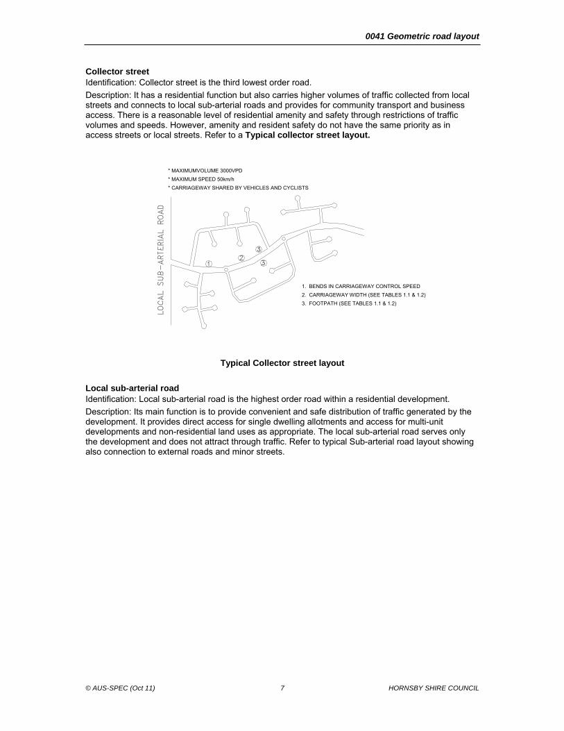
Collector street Identification: Collector street is the third lowest order road.
Description: It has a residential function but also carries higher volumes of traffic collected from local streets and connects to local sub-arterial roads and provides for community transport and business access. There is a reasonable level of residential amenity and safety through restrictions of traffic volumes and speeds. However, amenity and resident safety do not have the same priority as in access streets or local streets. Refer to a Typical collector street layout.
* MAXIMUMVOLUME 3000VPD
* MAXIMUM SPEED 50km/h
* CARRIAGEWAY SHARED BY VEHICLES AND CYCLISTS
Typical Collector street layout
Local sub-arterial road Identification: Local sub-arterial road is the highest order road within a residential development.
Description: Its main function is to provide convenient and safe distribution of traffic generated by the development. It provides direct access for single dwelling allotments and access for multi-unit developments and non-residential land uses as appropriate. The local sub-arterial road serves only the development and does not attract through traffic. Refer to typical Sub-arterial road layout showing also connection to external roads and minor streets.
1. BENDS IN CARRIAGEWAY CONTROL SPEED
2. CARRIAGEWAY WIDTH (SEE TABLES 1.1 & 1.2)
3. FOOTPATH (SEE TABLES 1.1 & 1.2)

0041 Geometric road layout
© AUS-SPEC (Oct 11) 8 HORNSBY SHIRE COUNCIL
Local sub-arterial road layout

0041 Geometric road layout
© AUS-SPEC (Oct 11) 9 HORNSBY SHIRE COUNCIL
Table 1.1 Characteristics of Roads in Residential Subdivision Road Networks
Road Type Carriageway Width (m)(1)
Parking Provisions Within Road Reserve
Kerbing Footpath Requirement (5), ( 9)
Bicycle path Requirement
(10)
Road Reserve Width
Comments
Access Street Single Lane: (2) 3.5
1 verge space per 2 allotments(2)
Integral kerb and gutter
No
No
See Note (3)
Two Lane:5.5 Carriageway As Above No No See Note (3)
Local Street 7.5 (Cul-de-sac end)
Carriageway
As Above
1.2m wide (4) footpath(s)
No
14.5m 2x3.5m nature strip, paved one side 1.2m.
9.0
(Through road)
Carriageway As Above As Above If on a bicycle route provide 2.5m bicycle/pedestrian path one side
16.0m 2x3.5m nature strip, paved one side 1.2m
Collector Street
11.0
Carriageway or Indented parking.
As above
1.2m wide footpath both sides.
2.5m bicycle/pedestrian path one side only in the verge
20.0m(8)
2x4.5 nature stirp to allow for local widening. 2.5m paved cycleway one side, 1.2m paved footpath other side
Local Sub-Arterial Road
13.0
Parking not permitted on carriageway (6)
As above If required 1.2m wide footpath, and/or 2.5m bicycle path one side only(7)
2.5m bicycle/pedestrian path one side only in the verge or two 1.5m wide bicycle lanes marked on carriageway.
22.0m(8) 2x4.5 nature strip to allow for local widening. 2.5m paved cycleway one side, 1.2m paved footpath other side

0041 Geometric road layout
© AUS-SPEC (Oct 11) 10 HORNSBY SHIRE COUNCIL
Table 1.2 Characteristics of Roads in Industrial Subdivision Road Networks
Road Type Carriageway Width (m)(1)
Parking Provisions Within Road Reserve
Kerbing Footpath Requirement (5), ( 9)
Bicycle path Requirement
(10)
Road Reserve Width
Comments
Access Street 11.0m
1 verge space per 2 allotments(2)
Integral kerb and gutter
No
No
18.0m(3) 1.2m paved footpath, both sides
Local Street 11.0 (Cul-de-sac end)
Carriageway
As Above
1.2m wide (4) footpath(s)
No
18m 1.2m paved footpath, both sides
11.0
(Through road)
Carriageway As Above As Above If on a bicycle route provide 2.5m bicycle/pedestrian path one side
18m 1.2m paved footpath, both sides
Collector Street
13.0
Carriageway or Indented parking.
As above
1.2m wide footpath both sides.
2.5m bicycle/pedestrian path one side only in the verge
22.0m(8)
1.2m paved footpath, both sides
Local Sub-Arterial Road
13.0 .
Parking not permitted on carriageway (6)
Barrier If required 1.2m wide footpath, and/or 2.0m bicycle path one side only(7)
2.0m bicycle/pedestrian path one side only in the verge or two 1.5m wide bicycle lanes marked on carriageway (6).
22.0m(8) 1.2m paved footpath, both sides
0041 Geometric road layout
© AUS-SPEC (Oct 11) 11 HORNSBY SHIRE COUNCIL
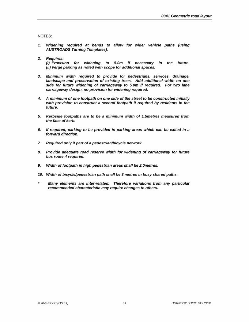
NOTES:
1. Widening required at bends to allow for wider vehicle paths (using AUSTROADS Turning Templates).
2. Requires: (i) Provision for widening to 5.0m if necessary in the future. (ii) Verge parking as noted with scope for additional spaces.
3. Minimum width required to provide for pedestrians, services, drainage, landscape and preservation of existing trees. Add additional width on one side for future widening of carriageway to 5.0m if required. For two lane carriageway design, no provision for widening required.
4. A minimum of one footpath on one side of the street to be constructed initially with provision to construct a second footpath if required by residents in the future.
5. Kerbside footpaths are to be a minimum width of 1.5metres measured from the face of kerb.
6. If required, parking to be provided in parking areas which can be exited in a forward direction.
7. Required only if part of a pedestrian/bicycle network.
8. Provide adequate road reserve width for widening of carriageway for future bus route if required.
9. Width of footpath in high pedestrian areas shall be 2.0metres.
10. Width of bicycle/pedestrian path shall be 3 metres in busy shared paths.
* Many elements are inter-related. Therefore variations from any particular recommended characteristic may require changes to others.

0041 Geometric road layout
© AUS-SPEC (Oct 11) 12 HORNSBY SHIRE COUNCIL
1.7 HIERARCHICAL ROAD NETWORK (TOWN CENTRE DEVELOPMENT)
Street types Street types are generally defined by their major uses and requirements for pedestrian, cycle, transit and vehicle movement. Six distinct street types are identified as follows. Road reserve characteristics are shown in Table 1.3. - Shared zones - Laneways - Village Street - Local Street (Type A and Type B) - Collector Road - Arterial road
Shared Zones A Shared Zone is a street shared safely by vehicles and pedestrians. It has a low speed limit of 10km/hr. Shared Zones are designed to support pedestrian and public life through alternative paving materials, removal of raised kerbs, footpath extensions and thresholds, seating, landscape treatments and pedestrian lighting that collectively creates a strong differentiation from traditional vehicle priority streets which reminds drivers that they should proceed cautiously and slowly.
Laneways Laneways are small scale streets that typically carry low numbers of vehicles and are mostly for local access only. Laneways can be used solely for service functions or they may have a partial or full closure to vehicular traffic and/or low speed restrictions in a dedicated shared zone environment.
Village Street Village streets make extensive use of traffic calming measures and reduced speed limit signage to discourage vehicular through-traffic, reduce vehicular speeds, green the landscape, creating a comfortable environment for pedestrian and bicycle movement. They are characterised by high levels of pedestrians and a wide pedestrian zone should be provided. The vehicle and pedestrian zones are separated and the street character and physical appearance responds to a mixed land use with a high volume of active retail and commercial frontages.
Local Streets (Type A and Type B) Type A Local Streets (mid-high activity streets): Type A Local Streets, similar to Village Main Streets support a balanced movement function between traffic and pedestrians. They serve as the secondary vehicular and primary pedestrian/cycle through routes/linkages, providing improved access for the medium density residential mixed use areas with local retail and commercial use.
Type B Local Streets (low-mid activity streets): Type B Local Streets support a balanced movement function between traffic and pedestrians. Traffic volumes are generally lower than Type A Local Streets and primarily function as access for low density residential. The typical speed of a Type B Local Street is 40km/hr.
Collector Roads Collector Roads are the primary circulation and access routes through neighbourhood. They serve as the secondary vehicular through routes/linkages, connecting the sub-arterial roads to the local system in developed areas. The vehicle and pedestrian zones are separated and the street character and physical appearance varies due to land use context.
Arterial Roads Arterial Roads are main or major routes through an area that is characterised by high volume vehicular traffic, increased speeds, signalised intersections and wider carriageways. The vehicle and pedestrian zones are separated and the street character and physical appearance varies due to land use context.

0041 Geometric road layout
© AUS-SPEC (Oct 11) 13 HORNSBY SHIRE COUNCIL
Table 1.3 Characteristics of Roads in Town Centre Development
Road Type Carriageway Width (m)
Parking Provisions Within Road Reserve
Kerbing Pedestrian through zone/Footpath Requirement
Bicycle path Requirement
Road Reserve Width
Public Domain/Furniture/ Planting Zone
Shared Zone
10.0m
No No 2.8m minimum pedestrian through zone both sides.
No
20.0m
Allow 2m planting/furniture zone both sides.
Laneway Varies. Minimum 4.5m
No Integral kerb and gutter.
1.5m minimum width footpath one side. If footpath does not meet the min 1.5m, a shared zone must be considered.
No Varies.
Village Street
8.0m Parking zone Integral kerb and gutter,
2.5m minimum pedestrian through zone and 1.0m minimum street furniture zone.
Integrated on road.
20.0m Allow for 2.5m wide flexible parking/planting/outdoor dining zone both sides.
Local Street Type A & Type B
7.5m (Cul-de-sac end)
Carriageway
Integral kerb and gutter.
2.0m wide footpath both sides.
No
14.5m Allow for 1.5m wide planting/street furniture zone both sides.
9.0m
(Through road)
Carriageway Integral kerb and gutter.
2.0m wide footpath both sides.
If on a bicycle route provide 2.5m. On-street painted bicycle lane.
16.0m Allow for 1.5m wide planting/street furniture zone both sides.
Collector Road
11.0-13.0m (existing)
11.0-12.0m (proposed)
Carriageway or indented parking.
Integral kerb and gutter.
Minimum 2.5m wide pedestrian zone both sides.
2.8m separated bi-directional cycleway to replace parking lane.
20.0m Allow for 1.5m minimum width planting/street furniture zone both sides.
Arterial Road
13.0m Parking not permitted on carriageway.
Integral kerb and gutter.
Minimum 2.5m wide pedestrian zone both sides.
Bicycle/pedestrian shared path on one side only.
22.0m Allow for 1.0m minimum width planting/street furniture zone both sides.

0041 Geometric road layout
© AUS-SPEC (Oct 11) 14 HORNSBY SHIRE COUNCIL
2 GENERAL DESIGN CONSIDERATIONS
2.1 CONSULTATION
Council and other authorities Responsibility: Consult with the Council and other relevant authorities during the preparation of design. In addition to the requirements of this worksection, identify the specific design requirements of these authorities.
Public consultation General: Undertake public consultation on designs if such action is required by Council policy.
Utilities service plans Existing services: Obtain service plans from all relevant utilities and other organisations whose services exist within the area of the proposed development. Plot these services on the relevant drawings including the plan and cross-sectional views.
Requirements for utility services: To Streets Opening Conference Guides to codes and practices for street openings.
Council approval
Where the Design is being carried out directly for Council and not for a Developer, a concept plan must be prepared for all projects and ratified with Council before proceeding with the more detailed final design.
2.2 PLANNING CONCEPTS
Road hierarchy Requirement: In new areas, as distinct from established areas with a pre-existing road pattern, ensure each class of route reflects its role in the road hierarchy by its visual appearance and physical design. Routes differ in alignment and design according to the volume of traffic they are intended to carry, the desirable traffic speed, and other relevant factors. Most road authorities have developed a functional hierarchy.
Integrated design principles Requirement: Integrate all design principles in the development of the road network to provide a balance between maximising amenity, safety and convenience considerations and those related to the drivers’ perception of appropriate driving practices.
Preparation for design: Design development inputs to conform to AGRD08.
Acceptable vehicle speed Requirement: Determine the acceptable vehicle speed for the particular section of road to AGRD03 clause 2.2.4.
Intersection turning movements Requirement: Minimise the number of turning movements at intersections or junctions that a driver is required to undertake to reach a particular property within the development.
Conformance with Development Control Plan Pattern and width: Conform to any relevant Development Control Plan (DCP). In areas not covered by such a plan, pattern and width(s) are determined by Council.
Legibility General: Design for clear legibility in conformance with the following:
- Differentiation: Reinforce legibility by providing sufficient differentiation between the road functions. (see Classifications)
- Landmark features: Emphasise distinct landmark features such as watercourses, mature vegetation or ridge lines within the structural layout so as to enhance the legibility.
- Introduced features: Provide the necessary legibility, by the inherent design and functional distinction of the road network in addition to introduced physical features such as pavement and lighting details

0041 Geometric road layout
© AUS-SPEC (Oct 11) 15 HORNSBY SHIRE COUNCIL
Environmental considerations Requirement: Evaluate the environmental considerations including topography, existing public utility services, visual intrusion, noise, vibration and pollution in the road design to AGRD03 clause 2.2.6. Noise reduction: Consider vertical alignment adjacent to intersections and/or sensitive areas (e.g. schools, hospitals) to minimize braking noise.
Salinity prevention Design constraints: For the design of roads through or adjacent to land known to be salt affected, take the following actions:
- Consultation: Consult with the relevant land and water resource authority.
- Early planning: Consider adjustments in horizontal and vertical line to avoid detrimental interference to and recharge of subsurface water within or adjacent to the road reserve.
- Landscaping: Select appropriate native deep-rooted species for plantings in association with road reserve works. Provide for plantations of sufficient size and density, multiple row belts and relatively close spacings, to lower the groundwater table.
Heritage considerations Requirement: Heritage sites are recorded in the State heritage asset register. Some sites may contain archaeological sites relating to Aboriginal or non-Aboriginal occupation. Plan for the management of heritage assets.
3 DESIGN CRITERIA
3.1 DESIGN CONSIDERATIONS
Design domain Design domain to AGRD02 clause 2
Traffic volume and composition Requirements: Determine the AADT to AGTM03.
3.2 ROAD NETWORK DESIGN CRITERIA
General Routing: Provide routing as follows:
- Avoid through routes in the internal road system that are more convenient than the external road network in conformance with AGTM08.
- Design and locate the external road network to provide routes that are more convenient for potential through traffic within the network.
- Provide access to major roads at intervals of no more than 1.5 km, of adequate capacity to accommodate through network movements.
Road links: Provide for road links as follows:
- Hierarchy: Except in exceptional circumstances, do not link one road with another that is more than two levels higher or lower in the hierarchy.
- Restriction: Avoid access from Access streets or Local streets to an access-controlled arterial road.
Traffic volumes and speeds: Ensure that the traffic volumes and speeds on any road are compatible with the residential functions of that road.
Road layout: Conform to the requirements of the external road network and satisfy the transport provisions of an outline development plan.
Travel time: Minimise the time required for drivers to travel on all streets within the development.
Internal road connections: Provide for intersections of internal roads as T-junctions or controlled by roundabouts.
Access street: Restrict the maximum length of an Access street to ensure that its status within a residential place is retained. Adopt design speed and volume to enable the integration of pedestrian, bicycle and vehicular movements without impairing residential convenience.
Local sub-arterial road: Minimise the length of local sub-arterial road within a development.

0041 Geometric road layout
© AUS-SPEC (Oct 11) 16 HORNSBY SHIRE COUNCIL
Pedestrian or bicycle network: Where Access streets form part of a pedestrian or bicycle network, provide for access links with adjoining access streets or open space systems to ensure functional efficiency of the pedestrian and bicycle network.
Traffic management in Activity Centres: Conform to AGTM07.
Traffic impacts of developments: Conform to AGTM12.
3.3 DESIGN SPEED
General State Road Authority guidelines: Use design speed as the basic parameter in road design. It is dependent on the functional classification of the road, topography, land use and abutting development and desired speed of drivers.
Design speed values for urban roads Requirement: Conform to the following operating speeds:
- Access street: 25 km/h.
- Local street: 50 km/h.
- Collector street: 60 km/h.
- Local sub-arterial road: 60/80 km/h.
- Speed limits: To AGTM05 Table 5.4.
- Typical urban operating speeds: To AGRD03 Table 3.1.
Operating speed model Model: Determine the operating speed using the operating speed model to AGRD03 clause 3.5 to predict the operating speed of cars along the length of the road where the operating speed varies with the horizontal curvature and is also dependent on the driver behaviour, road and the vehicle characteristics.
Hazard reduction Low speeds: Adopt a low design speed to discourage speeding. Avoid vertical or horizontal curves of low design speed located in otherwise high-speed sections to minimise the risk of creating a potentially dangerous section of road. Recognise that in low design speed roads, operating speeds may be in excess of posted speed limits.
Hazardous features: Make hazardous features visible to the driver. Adopt traffic engineering measures that help a driver avoid errors of judgement.
Road safety barriers: Assess and design road safety barriers to AS/NZS 3845.
Design speed values for rural roads Criteria: Determine the minimum design speed value for other elements for Council Works on the concept of a ‘speed environment’ as outlined in AGRD03 clause 3.4 and Table 3.2.
Requirement: Conform to the following operating speeds:
- High speed rural roads: > 90 km/h.
- Intermediate speed rural roads: 70-90 km/h.
- Low speed rural roads: 50-70 km/h.
Restricted access to major roads: Design all rural subdivisions to control access to major roads. Limit access to one point on to local, collector, local sub-arterial or arterial road networks.
3.4 CROSS-SECTION
Road reserve characteristics Cross section: Provide for all road functions including the following:
- Safe and efficient movement of all users.
- Provision for parked vehicles. Give particular attention to access for disabled persons in conformance with the Disability Discrimination Act.
- Access to public transport.
- Buffer from traffic acoustic nuisance for residents.
- Provision of public utilities
- Streetscaping.
- Requirements of Disability Discrimination Act.

0041 Geometric road layout
© AUS-SPEC (Oct 11) 17 HORNSBY SHIRE COUNCIL
Operational aspects: Conform to the following:
- Allow vehicles to proceed safely at the operating speed intended for that level of road in the network with only minor delays in the peak period.
- Take into consideration the restrictions caused by parked vehicles where it is intended or likely that this will occur on the carriageway.
- Vehicles include trucks, emergency vehicles and, on some roads, buses. (Refer to Bus route criteria table).
Type of cross-section General: Determine the type of cross-section considering the following factors:
Location
Function of the road
Type of road
Traffic volume
Public transport
Environmental constraints
Availability of construction materials
Design life: To AGRD03 Table 4.1.
Pedestrians and cyclists: Provide for the safety of pedestrians and cyclists where it is intended they use the carriageway by providing sufficient width and control of landscaping to provide sight distances.
Access to allotments: Adopt a carriageway width to provide for unobstructed access to individual allotments. Provide for drivers to comfortably enter or reverse from an allotment in a single movement, taking into consideration the possibility of a vehicle being parked on the carriageway opposite the driveway.
Traffic lanes General: Determine the number and width of the traffic lanes required depending upon the traffic volume, presence of cyclists, available road reserve width and the side friction constrained by abutting access.
Standard traffic lane width for urban and rural roads: 3.5 m.
Reduced lane width: If there are site constraints the traffic lane width may be reduced to 3.2 m subject to the approval of the relevant road authority.
Urban arterial road widths: To AGRD03 Table 4.3.
Single carriageway rural road widths: To AGRD03 Table 4.5.
Dual carriageway rural road widths: To AGRD03 Table 4.6.
Plan transitions Restrictions: In urban road design it is often impracticable to use plan transitions as kerb lines are fixed in plan and any shift requires carriageway widening. Widening on horizontal curves compensates for differential tracking of front and rear wheels of vehicles, overhang of vehicles, and transition paths. If proposed roads are curved, consider the adequacy of carriageway width.
Crossfall changes: To avoid abrupt changes in crossfall, which can cause discomfort in travel and create a visible kink in the kerb line, conform to the following:
- The wider the pavement the longer the transition.
- Use superelevation transitions at all changes in crossfall, not just for curves. Drainage problems can arise with superelevation transitions which may require extra gully pits and steeper gutter crossfalls.
- Where crossfalls change at intersections, draw profiles of the kerb line. Calculated points can be adjusted to present a smooth curve.
Crossfall General: Desirably, crown the roads on centerline. Provide crossfall to drain the carriageway on straights and curves and to provide superelevation on horizontal curves. Provide pavement crossfalls on straight roads for various pavement types to the Table 3.1.

0041 Geometric road layout
© AUS-SPEC (Oct 11) 18 HORNSBY SHIRE COUNCIL
Table 3.1
Type of pavement Crossfall (%)
Earth, loam 5
Gravel, water bound Macadam 4
Bituminous sprayed seal 3
Asphalt 2.5 – 3
Concrete 2 - 3
Recommended minimum crossfall: 2%.
Rate of change: Do not exceed the rate of change of crossfall in the following conditions:
- Through traffic: 6% per 30 m.
- Free flowing turning movements: 8% per 30 m.
- Turning movements for which all vehicles are required to stop: 12% per 30 m.
Precedence of crossfall over grade: Conform to the following:
- The crossfall on a Collector street or Local sub-arterial road will take precedence over the grade in Local or Access streets. Maintain the crossfall on the major road and adjust the local street levels to suit.
- A rate of change of grade of 2 % in the kerb line of the side street relative to the centre line grading is a reasonable level.
Shoulders Function: Design road shoulders to carry out the following functions:
- Structural: Provide lateral support to the road pavement layers.
- Traffic: Provide an initial recovery for an errant vehicle, emergency use, a refuge for stopped vehicles and space for cyclists.
Shoulder width: Provide the following:
- Generally: 1.5 – 2 m.
- For higher volume roads: 2.5 – 3 m.
Shoulder sealing: Seal the shoulders partially or wholly to reduce maintenance costs and to improve moisture conditions under pavements. Conform to the following sealed widths:
- Minimum width of shoulder seal for AADT < 1000: 0.5 m.
- For wet areas where moisture control is required:
. Desirable shoulder seal width: 0.5 m.
. Preferred shoulder seal width: 1 m.
- For discretionary stopping of cars: 2.5 m.
- For bicycles, minimum sealed width: 2 – 3 m.
Shoulder crossfall: Provide the following shoulder crossfall:
- For earth and loam: 5 – 6%.
- For gravel or crushed rock: 4 – 5%.
- For concrete and for full depth pavement with bitumen seal or asphalt wearing course: Match with the traffic lane.
Verge General: Design the verge to perform the following functions:
- A traversable transition between the shoulder and the batter slopes.
- A firm surface for stopped vehicles.
- Space for installation of guideposts and road safety barriers.
- Reduce scouring due to stormwater run-off.
Minimum width: To AGRD03 Table 4.9.
Verge rounding: Provide verge and batter toe rounding to minimise rollover accidents to AGRD03 Table 4.10.
Verge slope: Provide verge slopes for local roads or behind kerb and channel in cut:

0041 Geometric road layout
© AUS-SPEC (Oct 11) 19 HORNSBY SHIRE COUNCIL
- Without rounding: 5%.
- With rounding: Initial slope same as abutting shoulder.
Verges and property access Criteria: Design the verge with consideration of utility services, the footpath width, access to adjoining properties, likely pedestrian usage and preservation of trees.
Restriction: If normal crossfalls are impracticable adopt low level footpaths.
Crossfalls in footpath paving: < 2.5% to AGRD06A.
Longitudinal grade: Conform to the following:
- Parallel to the longitudinal grade of the road.
- Limit: May be steeper than 5%.
Driveway profile: Conform to the following:
- Provide a vehicular driveway centerline profile for the property access.
- Check the design using critical car templates, available from the Council.
- Design driveway profiles so that vehicles can use the driveway satisfactorily.
- In accordance with Council’s standard drawings.
- The conditions of Development Consent as applicable.
Batters Requirement: Accommodate differences in level across the road between road reserve boundaries by the following measures used individually or combined:
- Cutting at the boundary on the high side and providing the verge at normal level and crossfall.
- Battering at the boundary over half the verge width with the half against the kerb constructed at standard crossfall.
Batter slopes: Design the batter slopes considering the following factors:
- Recommendations of geotechnical investigations.
- Batter stability and safety.
- Available width of road reserve.
- Landscape requirements.
- Maintenance costs and accessibility requirements. Preferred maximum batter slope for a slasher is 4:1.
Design batter slopes: To AGRD03 Table 4.12.
Benches: Provide benches for high batters > 10 m vertical height or batters on unstable ground. Provide benches as shown in AGRD03 Figure 4.7.
- Minimum width of bench: 3 m.
- Maximum crossfall: 10%.
- Preferred bench width for road safety, maintenance and drainage: 5 m.
Roadside drainage General: Provide drains to remove water from the road and its surroundings and to maintain road safety and pavement strength. Provide table drains, catch drains, median drains or kerbs and channels.
Table drain: Provide a dish drain, or similar structure along the invert of table drains, seal the outer edges of the pavement, the shoulder verges and the drain lining where scour is likely to occur to AGRD03 Figure 4.8. Provide the following slopes:
- Side slopes: < 4H:1V.
- Desirable slope: 6H:1V.
Catch drains: Provide catch drains to prevent overloading of the table drain and scour of the batter face at least 2 m from the edge of cuttings to minimise possible undercutting of the top of the batter.
Median drains: Provide median drains with side slopes 10H:1V to reduce the chance of vehicle overturning. Provide a depressed median of minimum 10 m width. Place the invert of the median drain below subgrade level to facilitate drainage of pavement layers.
Kerb and channel: Provide kerb and channel to perform the following:
- Collect and convey surface drainage to a discharge point.

0041 Geometric road layout
© AUS-SPEC (Oct 11) 20 HORNSBY SHIRE COUNCIL
- Delineate the edges of the carriageway.
- Separate carriageways from areas dedicated to footpath users.
- Support the edge of the base course of the pavement.
- Reduce the width of cut by substituting an underground drainage system in place of table drains.
Kerb type and placement: Determine the type of kerb and placement to AGRD03 clause 4.6 and the following:
- Provide barrier kerb for lightly trafficked Local roads, adjacent to parking lanes and parking areas and bus bays to reduce the risk to pedestrians.
- Provide layback kerb on minor roads to allow for off-road parking and for continuous access to property.
Location: Place kerb and channel with the clearance between the face of the kerb and edge of the traffic lane to AGRD03 Table 4.13.
Rural roads: All rural residential subdivisions will be required to provide kerb and gutter on both sides of roads and piped drainage will generally be required.
Scour protection Requirement: Provide scour protection of roadside drainage and table drains. The level of protection will depend on the nature of the soils, road gradients and volume of stormwater runoff.
Protection of the works: Provide concrete lined channels, turfing, rock pitching, grass seeding, individually or in combination. Carry out geotechnical investigations to determine the level and extent of any protection works before proceeding to final design stage.
Medians General: Provide medians to improve the safety and operation of urban and rural roads with multiple lanes.
Median width: Minimum median width to AGRD03 Table 4.14.
Median slopes: Provide median slopes to AGRD03 Table 4.15.
Bicycle lanes General: Consider provisions for cyclists in the road design and provide adequate space for cyclists to share the road safely and comfortably by providing on-road bicycle facilities in the form of the following:
- Separate bicycle lanes: Provide separation from other motor traffic with exclusive bicycle lane on the left side of the road by pavement markings and signs.
- Road shoulders.
- Widened lanes for joint use by bicycles and other vehicles.
Bicycle lane width: To Table 3.2.
Restriction: Provide a minimum bicycle width of 2 m in congested areas.
Table 3.2
Lane width (m) Speed limit (km/h)
60 80 100
Desirable 1.5 2.0 2.5
Acceptable 1.2 - 2.5 1.8 – 2.7 2.0 – 3.0
Source: AGRD03 Table 4.17.
Minimum clearance with adjacent traffic on local roads: 1 m.
High occupancy vehicle (HOV) lanes General: If there are any public transport services proposed in the route, provide HOV priority lanes for public transport in conformance with the following:
- Shoulder width: 3.5 m.
- Intermittent bays: Provide bays with appropriate length tapers to provide safe movement of vehicles.
- Provide access to public transport in conformance with the Disability Discrimination Act.
Bus lane width: On new roads, conform to the following:
- To AGRD03 Table 4.21.

0041 Geometric road layout
© AUS-SPEC (Oct 11) 21 HORNSBY SHIRE COUNCIL
- Minimum width between the kerbs:
. If bicycle lanes are provided: 15 m.
. If bicycle lanes are not provided: 11.6 m.
- Kerbside width of bus lanes: To AGRD03 Table 4.22.
On-site parking On-site: Design on-site parking by determining the demand for parking to AGTM11, including the following:
- Accommodate on-site parking requirements for normal levels of activity associated with any land use.
- Ensure that the through traffic is not impeded.
- Locate all on-site parking of dimensions that allow convenient and safe access and usage.
- Number of on-site parking spaces for non-residential land uses: Conform to parking standards as determined by the relevant authority.
- The layout and access arrangements for parking areas for non-residential land uses: To AS/NZS 2890.1.
- On-site parking for people with disabilities: To AS/NZS 2890.6 and to the Disability Discrimination Act.
Number of on-site residential spaces: Conform to the following:
- Provide two car parking spaces (which may be in tandem) on-site for each single dwelling allotment.
- Refer DCP for car spaces for multi-unit residential developments.
Minimum dimension: Refer DCP for future spaces.
On-street parking Standards: To AS 2890.5, AGRD03 clause 4.10 and AGTM11.
Road reserve parking: Provide adequate parking within the road reserve for visitors, service vehicles and any excess resident parking since a particular dwelling may generate a high demand for parking.
Future spaces: Refer DCP for future spaces.
Short term truck parking: On single lane carriageways, combine a number of verge spaces to provide for short term truck parking within 40 m of any allotment.
Verge and carriageway parking: On single lane access streets, provide parking spaces within the verge. Provide verge and carriageway parking in conformance with the following:
- Adequate dimensions.
- Convenient and safe to access.
- Well defined with traffic control devices.
- All-weather surface.
- No restriction to the safe passage of vehicular, disabled and pedestrian traffic.
- Refer DCP for verge spaces and indented parking.
Joint use: For non-residential land uses, provide the opportunity for maximum joint use of shared parking by a number of complementary uses.
On-street parking dimensions: Conform to the following:
- Single (car) space: 6.5 m x 2.5 m
- Combined spaces for two cars:13.0 m x 2.5 m
- Truck parking: 20 m x 2.8 m with adequate tapers at both ends to allow parking manoeuvres determined to AP-G34.
Material: Construct all verge spaces and indented parking areas of concrete, interlocking pavers, lawn pavers, bitumen with crushed rock or other suitable base material designed to withstand the loads and manoeuvring stresses of vehicles expected to use those spaces.
Right-angled parking: Refer DCP for right-angled parking.
Angled parking space widths: To AS 2890.5 Table 2.2.
Service roads and footpath General: Service roads provide access to the abutting property or control access to the arterial road from the abutting property.

0041 Geometric road layout
© AUS-SPEC (Oct 11) 22 HORNSBY SHIRE COUNCIL
Minimum service road lane width: To AGRD03 Table 4.25.
Minimum service road carriageway width for roads with low traffic volumes: To AGRD03 Table 4.26.
Operating speed: 40-60 km/h.
Outer separator width: To AGRD03 Table 4.27
Urban border: Provide urban borders comprising of a pedestrian path and the nature strip to AGRD03 Table 4.28, to ensure the following:
- Separate pedestrians from vehicular traffic.
- Provide off-road bicycle facilities.
- Provide for indented bus bays.
- Take up level differences between the carriageway and the boundaries of the adjacent properties.
- Provide for public utility services and drainage.
Typical urban border slopes: Conform to the following:
- For footpaths
. Desirable: 1%
. Maximum: 2.5%
- Nature strip:
. Grassed soil: 4-10%
- Determine minimum slope on urban borders by considering the drainage.
- Determine the maximum slope by considering the terrain and provision of access at driveways.
Footpaths: Provide footpaths either adjacent to the roadway or separated from it by a nature strip.
Standard: To AGRD06A.
Minimum desirable width: 1.2 m.
Crossfall: Varies from flat to 2.5%.
Bus stops New bus stops: In conformance with the requirements of the Disability Discrimination Act (Australian government 1992) and other road authorities and transport agency disability standards which outline the requirements of the access paths, manoeuvering areas, ramps, waiting areas, surfaces and tactile ground surface indicators.
Urban bus stops: To AGRD03 Figure 4.39 provides a typical bus bay layout.
Rural bus stops: Locate bus stops in the road shoulder between the carriageway and table drain.
Minimum shoulder width for a bus stopping area: 3 m.
Minimum length of bus stopping area: 15 m.
For intermediate speed environments provide a longer sealed distance: 30-50 m.
3.5 SIGHT DISTANCE
General Stopping and sight distance: Provide stopping and sight distance at all points on the road conforming to AGRD03 Section 5.
Sight distance parameters: To AGRD03 Table 5.1 and the following:
- Object cut-off height: 0.2 m.
- Driver eye height: Adopt the following:
. For cars: 1.1 m.
. For commercial vehicles: 2.4 m.
- Driver reaction time: Adopt reaction time of 2.5 seconds for all roads. If 1.5 seconds and 2 seconds reaction times are required, arrange approvals from the State Road Authority. AGRD03 Table 5.2 provides further details on reaction times.
Stopping sight distance: Conform to the following:
- General: To AGRD03 clause 5.3, measured from an eye height of 1.15 m to an object height of 0.20 m.
- On sealed roads: Car stopping sight distance to AGRD03 Table 5.4.

0041 Geometric road layout
© AUS-SPEC (Oct 11) 23 HORNSBY SHIRE COUNCIL
- On horizontal curves: To AGRD03 Figure 5.4.
- On horizontal curves with roadside barriers: Provide minimum shoulder widths and manoeuvre times for sight distances over roadside safety barriers on horizontal curves to AGRD03 Table 5.6.
Horizontal curve perception sight distance: Provide sufficient sight distance by adopting larger crests for a horizontal curve. Do not provide a horizontal curve starting over a crest. Check sufficient visibility is provided for the curve by providing:
- Clear driver eye height: 1.1 m.
- A zero object height such that the driver can see the road surface in order to perceive the curvature.
- Driver visibility of a minimum of:
. 5 degrees of arc.
. 80 m of arc.
. The whole curve.
3.6 COORDINATION OF HORIZONTAL AND VERTICAL ALIGNMENT
Horizontal and vertical alignment coordination General: The 3 dimensional coordination of the horizontal and the vertical alignment on the road aims to increase efficiency, safety, encourage uniform speed, improve aesthetics, provide harmony with the landform and drainage.
Requirement: Conform to the following:
- Avoid the use of minimum radius horizontal curves with crest vertical curves.
- Contain the crest vertical curves within horizontal curves to enhance the appearance of the crest by reducing the three dimensional rate of change of direction and to improve safety.
- Provide the same design speed of the road in both horizontal and vertical planes.
- Avoid sharp horizontal curves at or near the top of a crest vertical curve.
- Consider three dimensional combined horizontal and vertical stopping sight distance and minimum sight distance.
- Provide a horizontal curve to indicate the change in direction before introduction of vertical curve in both directions of travel.
- Be aware that a short vertical curve on a long horizontal curve or a short tangent in the grade-line between sag curves may adversely affect the road’s symmetry and appearance.
Aesthetic consideration: Conform to the following:
- Provide horizontal curves slightly longer than the vertical curve, such that the curves fits with the terrain and are coincident.
- Provide long horizontal curves to short curves such that:
. The overtaking opportunities are not reduced.
. Small deflection angles avoid the appearance of a kink.
. Best appearance is provided for deviations around obstructions.
. The far tangent point is beyond the driver’s point of concentrated vision for curves located at the end of long straights.
Drainage consideration: To ensure pavement drainage and to reduce the risk of aquaplaning, avoid very long crest and sag curves, that result in long sections of flat grades at the top and the bottom of the curves.
3.7 HORIZONTAL ALIGNMENT
General Requirement: Provide horizontal alignment for safe and continuous vehicle operation at a uniform travel speed. Include the following:
- For low and intermediate speed rural roads and minor urban roads, where physical restrictions curve radii cannot be overcome, introduce curvature of a lower standard than the design speed of the project to AGRD03 Table 7.1.
- Provide tangents of suitable length as frequently as the terrain permits to facilitate overtaking manoeuvres.

0041 Geometric road layout
© AUS-SPEC (Oct 11) 24 HORNSBY SHIRE COUNCIL
- Determine the horizontal alignment from the design speeds for a particular street within the road hierarchy (see Design Speed).
Horizontal curves Types of horizontal curves: Conform to the following:
- Compound curves: Provide a smaller curve preceding a larger curve. Avoid diminishing radii at steep downgrades.
- Reverse curves: Do not use reverse curves unless there is sufficient distance between the curves to introduce full superelevation of the two curves without exceeding the standard rate of change of crossfall for a particular design speed.
- Transition curves: Join the straight and circular curves to smooth the travel of vehicles within the traffic lane. Transition the horizontal curves with the transition length based on the superelevation runoff length for the recommended combination of speed, radius and superelevation. Avoid transition curves for large radius horizontal curves and where operating speed is less than 60 km/h. Where lane width is ≤ 3.5 m, provide transition paths for trucks.
Horizontal curves and tangent lengths Speed/radius relation: Conform to the following:
- For a given design speed, utilise the minimum radius of curvature that ensures that drivers can safely negotiate the curve.
- Avoid curves that progressively tighten (e.g. parabolic curves) and sudden reverse curves that drivers cannot anticipate as they have the potential to produce an uncomfortable sense of disorientation and alarm.
Speed restriction: Where speed restriction is provided by curves in a street, conform to the relationship between the radius of the curve and the desired vehicle speed.
Tangents: Determine appropriate lengths for tangents between speed restrictions, which may be curves, narrow sections or other obstructions.
Sight distance: Determine the sight distance on curves to AGRD03 clause 5.4.
Side friction and minimum curve size Recommended side friction factors: To AGRD03 Table 7.4.
Minimum radii for horizontal curves based on superelevation and side friction: To AGRD03 Table 7.5.
Maximum allowable deflection angles without horizontal curves: To AGRD03 Table 7.6.
Superelevation Requirement: Use of superelevation in association with horizontal curves for geometric design of roads with all design speeds.
Criteria: Determine the superelevation by including the following:
- Operating speed of the curve.
- Difference between the inner and outer formation levels in flat or urban areas
- Stability of high vehicles when adverse crossfall is considered.
- Length available to introduce the necessary superelevation.
Minimum radius of curves: Determine from the following:
- Design speed.
- Minimum superelevation (or maximum adverse crossfall) at any point on the circular portion of the curve.
Low design speed and crowned pavement: Conform to the following:
- Access and Local streets: For design speeds of 50 km/h or less, and curves of 60 m radius or less, generally have the pavement crowned on a curve instead of superelevation.
Superelevation in rural roads: Design superelevation, widening and centreline shift and transitions in conformance with the AGRD03 clause 7.7.
High design speed: Conform to the following:
- Maximum superelevation for urban roads of higher design speeds: 6%.
- Maximum values for different road types: To AGRD03 Table 7.7.
- Avoid any increase in the longitudinal grade leading to excessive crossfall at intersections.
- While it is desirable to superelevate all curves, limit adverse crossfall to 3%.

0041 Geometric road layout
© AUS-SPEC (Oct 11) 25 HORNSBY SHIRE COUNCIL
Length of superelevation: Design superelevation development lengths to satisfy both rate of rotation and relative grade criteria to AGRD03 Table 7.9.
Transitions: Conform to the following:
- Planning: Plan transitions on superelevated curves for appearance and to provide sufficient length in which to apply the superelevation.
- Urban roads: Superelevation may be conveniently applied to the road cross section by shifting the crown to 2 m from the outer kerb, as long as the road is not too wide.
- Access to adjacent properties: The axis of rotation of the cross section for urban roads is normally the kerb grading on either side which best enables access to adjacent properties and intersections.
- On the outside of superelevation, or where the longitudinal grade of the gutter is < 0.5%, adopt a crossfall of 63 mm in a 450 mm wide gutter.
Curves with adverse crossfall General: Avoid adverse crossfall greater than 3% except for curves with an operating speed ≤ 70 km/h in constrained areas and for intersection turns and roundabouts.
Minimum radii with adverse crossfall: To AGRD03 Table 7.10.
Adverse superelevation: Provide adverse superelevation at the following:
- Property access controls.
- Channel drainage controls.
- Grading restrictions.
- Intersections to maintain visibility of the road surface.
Pavement widening on horizontal curves Widening: Provide pavement widening on curves to AGRD03 Table 7.11 to maintain lateral clearance between vehicles taking into account the following factors:
- Radius of the curve.
- Width of lane on a straight road.
- Vehicle length and width.
- Vehicle clearance.
3.8 VERTICAL ALIGNMENT
General Documentation: Show vertical alignment on a longitudinal section with a vertical scale of 10H:1V.
Vertical controls Requirement: Consider the effect of the following features on the vertical geometric design:
- Existing topography.
- Geotechnical conditions.
- Existing intersections.
- Property entrances.
- Pedestrian access.
- Service utility assets.
- Median openings.
Minimum clearance above flood levels and water tables: As defined by the relevant road authority.
Vertical clearances General: Provide minimum vertical clearances over roadways and pedestrian/cycle paths to AGRD03 Table 8.1.
Precedence: If there is a conflict the following order takes precedence:
- Policies of the road owning authority e.g. Council, State Road Authority.
- Requirements of the authority that owns the object e.g. rail authority.
Underground services Clearance requirements: Consult the relevant authority to determine the minimum clearance requirements for:
- Gas mains.

0041 Geometric road layout
© AUS-SPEC (Oct 11) 26 HORNSBY SHIRE COUNCIL
- Water mains.
- Stormwater drains.
- Sewer outfall.
- Telecommunication cables.
- Underground electrical cables.
- Road authority assets e.g. traffic signals and street lighting.
Longitudinal gradient General: Provide grades as flat as possible, consistent with longitudinal drainage requirements such that all vehicles operate at the same speed. Conform to the following minimum grades:
- Road with kerb and channel:
. Minimum desirable grade: 1%
. Absolute minimum grade: 0.3%.
- Roads in cut:
. Unlined drains: 0.5%.
. Lined drains: 0.3%.
- Roads without kerb and channel and not in cut: 0%.
- Minimum gradient of 0.5%.
- In very flat conditions: Reduce grade to 0.3%.
- If underground drainage with gully pits or other special works are used: Consider near level grades. Provide variable crossfall to achieve the required grade in the gutter.
Maximum grade: Maximum grades are shown in Table 3.3.
Table 3.3
Local access road
Collector road
Local sub- arterial road
Rural road
Desirable maximum percentage*
12 10 8 10
Absolute maximum percentage*
20 12 10 12
* maximum length 150 m on straight alignment. * If any section of the road has a grade over 16%, the whole road pavement shall have concrete pavement in accordance with the Specification 0042 Pavement Design.
Intersections: Conform to the following:
- Longitudinal grade of the minor street on the approach to an intersection: < 4%.
- Design actual gradient dependent on the type of terrain.
- Interrelate the design of the road alignments and the grades used.
- Avoid a steep grade on a minor side street if vehicles have to stand waiting for traffic in the major road.
Maximum grade in cul-de-sacs and turning circles: < 5 %.
Vertical curves Criteria: Design vertical curves in conformance with the following:
- Provide vertical curves like simple parabolas on all changes of grade exceeding 1%.
- Desirable minimum design speed: 40 km/h.
- The length of the crest vertical curve for Stopping Sight Distance: To AGRD03 Table 8.7.
- Limit the length of crest curve with 0.3% to 0.5% grade: 30 to 50 m.
Sag curves: Provide the lengths of sag vertical curves to AGRD03 clause 8.6.4 and the following:
- Minimum length: Minimum length to conform to Table 3.4.

0041 Geometric road layout
© AUS-SPEC (Oct 11) 27 HORNSBY SHIRE COUNCIL
- For kerbed roads: Limit the maximum length of sag curves with less than 0.3% grade to 30 m.
- Maintain a minimum grade of 0.5% in the kerb and gutter. This may require some warping of road cross sections at sag points.
Table 3.4 Minimum Length of Sag Vertical Curves
Local access street (m)
Collector street (m)
Local Sub-Arterial road
(m)
Minimum vertical curve 25 35 50
Absolute minimum vertical curve (to be applied at road junctions only)
10
12
20
Sag vertical curves: As residential roads are usually lit at night, the criterion for designing sag vertical curves is a vertical acceleration of the following:
- For desirable riding comfort: 0.05 g.
- For minimum riding comfort: 0.10 g.
Side road intersections: Locate intersections of roads at a safe distance from a crest, determined by visibility from the side road. If it is proposed to locate intersections of a side road where a crest occurs, provide details with justifications.
3.9 AUXILIARY LANES
General Requirement: Provide auxiliary lanes adjacent to the through traffic lanes to enhance traffic flow and maintain the required level of service where an Arterial road meets with the Sub-arterial, Collector or Local roads.
Types of auxiliary lanes Speed change lanes: Provide speed change (acceleration or deceleration) lanes at intersections or interchanges to allow an entering vehicle to access the traffic stream at a speed approaching or equal to 85th percentile speed of the through traffic.
Overtaking lanes/climbing lanes: Provide overtaking lane lengths to AGRD03 Table 9.2 and merge sight distance at the end of overtaking to AGRD03 Table 9.3.
Slow vehicle turnouts: Provide a short section of paved shoulder to allow vehicles to pull aside and be overtaken. Provide turnout lengths of 60 – 160 m for average approach speed of 30 – 90 km/h and a width of 3.7 m.
Cross-section Auxiliary lane width: Provide auxiliary lane width not less than the normal width for that section of the road.
Shoulder width: 1 m.
Crossfall: Provide same crossfall of the auxiliary lane as the adjacent lane.
3.10 INTERSECTIONS
Design criteria Requirement: Consider the following factors in the location and design of intersections:
- Alignment and grade of approach road.
- Provision of drainage.
- Interference with public utilities.
- Property access.
- Topography.
- Natural and built environment.
Urban and rural intersections: To AGRD04 Table 4.1.

0041 Geometric road layout
© AUS-SPEC (Oct 11) 28 HORNSBY SHIRE COUNCIL
Road users considerations: To AGRD04 Table 3.2.
Design criteria: Design intersections to AGTM06.
Intersection types Traffic management: Select the type of intersections for traffic management in conformance with AGTM06 Table 2.4.
The basic forms of an intersection may include the following:
- Signalised, unsignalised or a roundabout.
- Channelised (i.e. has traffic islands and/or medians) to develop specific types of intersections, or unchannelised.
- Flared, to provide additional through and/or turning lanes, or unflared.
- An urban or rural intersection to which different driver expectations and hence different design and traffic management guidelines may apply.
Location Requirement: Locate intersections to AGRD04 Table 4.2 and the following:
- Streets intersection: Preferably at right-angles and not less than 70º.
- Landform: Allowing clear sight distance on each of the approach legs of the intersection.
- Minor street: Intersect the convex side of the major street.
- Vertical grade lines at the intersection: Conform to the following:
. Provide a desirable grade of 3%with a maximum of 5%.
. Allow for any direct surface drainage.
- For a left turn, where two minor side streets intersect a major street in a staggered pattern, provide to have a minimum centreline spacing of 40 m.
Traffic volumes: Design for all movements to occur safely without undue delay. Use projected traffic volumes in designing all intersections or junctions on Local sub-arterial roads.
State roads and national highways: Design intersections for the junction of Council’s roads with existing state rural or urban roads and national highways to AGRD04.
Approval of State Road Authority: Design intersections with state roads or national highways in conformance with the requirements of the State Road Authority.
Sight distance: Provide adequate stopping and sight distances for horizontal and vertical curves at all intersections.
Parking: Where required, make appropriate provision for vehicles to park safely.
Drainage: Design the road reserve cross-section profile to satisfy the drainage function of the carriageway and/or road reserve.
Turning movements: Accommodate all vehicle turning movements in conformance with AP-G34 and the following:
- For intersection turning movements involving Local sub-arterial roads: Provide for the ‘design semi-trailer’ with turning path radius 19.0 m.
- For intersection turning movements involving Local streets or Collector streets, but not Local sub-arterial roads: Provide for the ‘design single unit’ bus with turning path radius 12.5 m.
- For intersection turning movements on access streets but not involving local sub-arterial roads, collector streets or local streets: Provide for the garbage collection vehicle used by the local authority.
- For turning movements at the head of cul-de-sac access streets: Provide for sufficient area for the ‘design single unit’ truck to make a three-point turn or, if the length of the cul-de-sac is less than 60 m, for the ‘design car’ to make a three-point turn. If driveway entrances are used for turning movements, design the required area to withstand the relevant loads.
Turning radii at intersections or driveways on Local sub-arterial road: Design for the intended movements within desired speeds to be exceeded to AGRD04 Table 5.1.
Bus facilities: Provide minimum length required for bus lane on an intersection to AGRD04 Table 6.1.
Minimum width of bicycle and bus lanes: To AGRD04 Table 6.2.

0041 Geometric road layout
© AUS-SPEC (Oct 11) 29 HORNSBY SHIRE COUNCIL
Sight distance Sight distance: Provide adequate horizontal and vertical sight distance at intersections. Examine each intersection location for conformance with the criteria for Approach Sight Distance (ASD), Minimum gap sight distance (MGSD) and Safe Intersection Sight Distance (SISD). Ensure ASD and SISD are achieved for all intersections, and MGSD where appropriate. Reposition an intersection if required to obtain conformance with the following sight distance criteria:
- ASD: To AGRD04A Table 3.1 and grade corrections to AGTM06 Table 3.3 for sealed roads.
- MGSD: To AGRD04A Table 3.5 for various speeds.
- SISD: Provide SISD for sealed roads to AGRD04A Table 3.2.
Type of turn treatments General: Provide the appropriate type of right-turn and left-turn treatments from the following:
- Basic turn treatment (Type BA)
. Rural basic (BA) turn treatment: To AGRD04A Figure 4.1.
. Rural basic left-turn treatment for minor roads: To AGRD04A Figure 8.2, width minimum length of widened parallel shoulder to AGRD04A Table 8.1.
. Urban basic (BA) turn treatment: To AGRD04A Figure 4.2.
- Auxiliary lane turn treatment (Type AU): Provide short lengths of auxiliary lane to improve safety on high speed roads where an arterial road meets with sub-arterial, collector or local roads. Provide the following turn treatments as appropriate:
. Rural auxiliary lane turn treatments: To AGRD04A Figure 4.5.
. Urban auxiliary lane turn treatments: To AGRD04A Figure 4.6.
. Urban auxiliary left-turn treatment – Short turn lane (AUL(S)) major road: To AGRD04A Figure 8.10 with setting out details of the left turn geometry to AGRD04A Table 8.4 and with minimum kerb radii for low speed environment to AGRD04A Table 8.3.
- AUR right turn treatments: Not as safe as a channelised treatment at unsignalised intersections. Prefer not to use and many state and territories do not approve.
- Channelized turn treatment (Type CH):
. Rural channelised (CH) intersection turn treatment: Layout to AGRD04A Figure 4.7 and design details to AGRD04A Figure 8.5 and Figure 8.6.
. Urban channelised (CH) intersection turn treatment: Layout to AGRD04A Figure 4.8 and design details with a high entry angle left-turn island to AGRD04A Figure 8.12 and Urban CHL with acceleration lane to AGRD04A Figure 8.13.
Staggered T-intersections: Rural staggered T intersections may be ‘right to left’ or ‘left to right’ type to AGRD04A Section 4.11. Each type has either safety or cost advantages. Consider traffic volumes and available width in design selection. Provide staggered T-intersections by:
- Setting out the alignment of the minor roads on new major roads to form a staggered T-intersection.
- Realigning one or both minor road legs of an existing intersection.
3.11 ROAD NETWORK ELEMENTS
Roundabouts Design criteria: To AGRD04B and AGTM 06 Section 4. If alternative criteria is proposed , submit alternative criteria for consideration.
General: Provide the following:
- Functional design: To achieve safety of all users and traffic performance.
- Entry width: To provide adequate capacity.
- Adequate circulation width: Compatible with the entry widths and design vehicles (eg. buses, trucks, cars).
- Central islands: Of diameter sufficient only to give drivers guidance on the manoeuvres expected.
- Deflection of traffic to the left on entry: To promote gyratory movement.
- Adequate deflection of crossing movements to ensure low traffic speeds.
- A simple, clear and conspicuous layout.
- Design to ensure that the speed of all vehicles approaching the intersection will be less than 50 km/h.

0041 Geometric road layout
© AUS-SPEC (Oct 11) 30 HORNSBY SHIRE COUNCIL
Approval: Obtain approval of roundabouts from the Council and the relevant State Road Authority.
Traffic calming Design criteria: Calming devices (e.g. thresholds, slowpoints, speed humps, chicanes and splitter islands) to AGTM08. Select the type of local area traffic management devices from AGTM08 Table 7.1.
Local area traffic management(LATM) devices: Conform to the following:
- Streetscape:
. Reduce the linearity of the street by segmentation.
. Avoid continuous long straight lines (e.g. kerb lines).
. Enhance existing landscape character.
. Maximise continuity between existing and new landscape areas.
- Location of devices/changes:
. Other than at intersections, maintain consistency with streetscape requirements.
. For compatibility with existing street lighting, drainage pits, driveways, and services.
. Slowing devices optimally at spacings of 100 m to 150 m.
- Design vehicles:
. Ensure emergency vehicles are able to reach all residences and properties.
. Local streets with a ‘feeding’ function between arterial roads and minor local streets may be designed to AP – G34 templates.
. Bus routes: Allow buses to pass without mounting kerbs and with minimal discomfort to passengers.
. Provide for building construction traffic in newly developing areas where street systems are being developed in line with LATM principles.
- Control of vehicle speeds:
. Reduce speed using devices which shift vehicle paths laterally (slow points, roundabouts, corners) or vertically (humps, platform intersections, platform pedestrian/school/bicycle crossings).
. Create a visual environment conducive to lower speeds. This can be achieved by ‘segmenting’ streets into relatively short lengths (less than 300 m), using appropriate devices, streetscapes, or street alignment to create short sight lines.
- Visibility requirements (sight distance):
. Provide critical sight distances so that evasive action may be taken by either party in a potential conflict situation. Relate sight distances to likely operating speeds.
. Consider sight distance to include those of and for drivers, pedestrians and cyclists.
. Ensure night time visibility of street features. Locate speed control devices near existing street lighting if practicable and delineate all street features/furniture for night time operation. Provide additional street lighting at proposed new speed control devices located away from existing street lighting.
- Safety: Provide roadside design that conforms with AGRD06 including:
. Safety barriers.
. Treatment options.
. Steep down grades.
Critical dimensions. Dimensions: Conform to the following:
- Pavement narrowings:
. Single lane between kerbs: 3.50 m.
. Single lane between obstructions: 3.75 m.
. Two lane between kerbs: Minimum 5.50 m.
- Plateau or platform areas: 75 mm to 150 mm height maximum, with 1 in 15 ramp slope relative to road grade.

0041 Geometric road layout
© AUS-SPEC (Oct 11) 31 HORNSBY SHIRE COUNCIL
- Width of clear sight path through slowing devices: 1.0 m maximum (i.e. the width of the portion of carriageway which does not have its line of sight through the device blocked by streetscape materials, usually vegetation).
- Mountable areas required for the passage of large vehicles: To appropriate turning templates.
Approval: Obtain approval of traffic calming devices from the Council.
Bus routes Criteria: Conform to the following:
- Design the road hierarchy to cater for buses on routes identified by the Council.
- Location of bus routes and bus stops: Arrange so that no more than 5% of residents have to walk in excess of 400 metres to catch a bus.
- Design roads above the Local street level in the network hierarchy as bus routes.
Dimensions: To the Table 3.5.
Table 3.5 Bus route criteria table
Road Carriageway Width (min)
Stops (Spacing) Bays
Collector* 9 m 400 metre ** Single
Local sub-arterial 11 m 400 metre Shelters***
Arterial 13 m 400 metre Shelters and bays
* Collector roads not identified as bus routes may have 7 m carriageways. ** Loop roads with single entry/exit only require stops and bays on one side road. *** Shelters are subject to Council’s requirements.
4 DOCUMENTATION
Design process System: Develop a flow chart to incorporate the brief, consultation, selection of design parameters, approvals and critical dates.
Design review, verification and validation: Provide design documentation that conforms with AGRD08.
Design calculations Calculations: Provide results and reference software used for relevant distance or curvature calculations. If friction is a factor in layout/geometry, note the pavement type assumed for surface conditions and noise minimisation.
Drawing requirements Drawing scale: Conform to the following:
- All plans for Council works: 1:500. However, rural plans may be 1:1000.
- Longitudinal sections: 1:500 Horizontal and 1:100 Vertical.
- Cross Sections: 1:100 Natural.
Drawing sheets Requirement: Provide separate sheets for the following:
- Cover.
- Plan views.
- Longitudinal sections.
- Cross sections.
- Structural details.
- Standard drawings.
Drawing presentation Plain English: Drawings form part of the permanent record and are legal documents. Keep terminology in plain English, enabling drawings to be easily read and understood by those involved in the construction of the Works.
Drawings: Present drawings on A1 sheets unless otherwise authorised. Prepare clear and legible drawings with consistent lettering and style, and clearly referenced with notations and tables as appropriate.

0041 Geometric road layout
© AUS-SPEC (Oct 11) 32 HORNSBY SHIRE COUNCIL
Compliance Consistency: Provide drawing sheets consistent with the scope and sequence of the example provided in Annexure B of 0010 Quality (Design).
Certification Approval: Drawings are signed by the Council Designer or Council’s Consultant and where required by Council, certify as complying with the appropriate design worksections.
Certificate format: To 0010 Quality (Design).


![0041 Mises - Teoria e Historia [Pasajes]](https://img.dokumen.tips/doc/110x75/54e414bf4a795939618b4995/0041-mises-teoria-e-historia-pasajes.jpg)


