Embed Size (px)
Citation preview

DEVELOPMENT APPLICATION
PDPLANPMTD-2019/003553
APPLICANT: Creative Homes Hobart
PROPOSAL: Dwelling
LOCATION: 14 Boultbee Place, ROKEBY
RELEVANT PLANNING SCHEME: Clarence Interim Planning Scheme 2015
ADVERTISING EXPIRY DATE: 30 September 2019
In addition to the Application Form(s), Certificate of Title(s) and any associated
consent documents the following information is available on request:
• Nil
The relevant plans and documents can be inspected at the Council offices, 38 Bligh
Street, Rosny Park, during normal office hours until 30 September 2019.
Any person may make representations about the application to the General
Manager, by writing to PO Box 96, Rosny Park, 7018 or by electronic mail to
[email protected]. Representations must be received by Council on or before
30 September 2019.
To enable Council to contact you if necessary, would you please also include a day
time contact number in any correspondence you may forward.
Any personal information submitted is covered by Council’s privacy policy, available
at www.ccc.tas.gov.au or at the Council offices.

PROJECT ADDRESS: 14 BOULTBEE PLACE, ROKEBY
TITLE REFERENCE: VOLUME: 175194 FOLIO: 440
CLIENTS: MR PETER YANBIN & MRS SARAH LI
DESIGNER: INGE BROWN, CC 6652
DRAWINGS: 01 PROPOSED SITE PLAN02 PROPOSED FLOOR PLAN03 PROPOSED ROOF PLAN04 PROPOSED ELEVATIONS05 PROPOSED ELEVATIONS06 SECTION A-A07 WINDOW SCHEDULE
FLOOR AREAS:FLOOR AREA: 129.3m²PORCH: 1.8m²GARAGE: 21.4m²ALFRESCO: 10.7m²
TOTAL AREA: 162.4m²
SOIL CLASSIFICATION: S
WIND CLASSIFICATION: N2
CLIMATE ZONE: 7
BUSHFIRE ATTACK LEVEL: N/A
ALPINE AREA: N/A
CORROSION ENVIRONMENT: N/A
Creative HomesHOBART

PROPOSED RESIDENCELOT 440
FFL RL. 39.65
3200
1500
4500
DRIVEWAY72.8m²
PORCH
GARAGEALFRESCO
1500
5380
EXTENT OF EXCAVATIONDPDPDP
DP DP
IMPORTANT!SITE INFORMATION AS DRAWN ISAPPROXIMATE ONLY. FINAL SITEINFORMATION IS SUBJECT TO ADETAILED CONTOUR SURVEY BY
LICENSED SURVEYOR.
GENERAL NOTES:
1. THIS PLAN HAS BEENPREPARED BY SURVEY PLUSFROM A COMBINATION OFEXISTING RECORDS AND FIELDSURVEY FOR THE PURPOSES OFSHOWING THE PHYSICALFEATURES OF THE LAND ANDSHOULD NOT USED FOR ANYOTHER PURPOSE.
2. TITLE BOUNDARIES SHOWNWERE NOT VERIFIED OR
MARKED AT THE TIME OF THISSURVEY.
3. SERVICES SHOWN ON THISPLAN WERE LOCATED WHEREPOSSIBLE BY FIELD SURVEY.THEY ARE NOT A COMPLETEPICTURE OF SERVICES ON SITE.ALL SERVICE LOCATIONS ARETO BE VERIFIED BEFORECOMMENCEMENT OF ANYWORK ON SITE, IN PARTICULARTHOSE SERVICES NOT
PREVIOUSLY LOCATEDTHROUGH FIELD SURVEY.
4. SURVEY PLUS CAN NOTACCEPT LIABILITY WHATSOEVERFOR LOSS OR DAMAGECAUSED TO ANYUNDERGROUND SERVICEWHETHER SHOWN BY OURSURVEY OR NOT.
5. THIS NOTE IS AN INTEGRALPART OF THIS PLAN/DATA.REPRODUCTION OF THIS PLAN
OR ANY PART OF IT WITHOUTTHIS NOTE BEING INCLUDED INFULL WILL RENDER THEINFORMATION SHOWN ONSUCH A REPRODUCTIONINVALID AND NOT SUITABLEFOR USE WITHOUT PRIORAUTHORITY OF SURVEY PLUS
6. HORIZONTAL DATUM IS MGA(Map Grid Australia)
7. VERTICAL DATUM ISARBITRARY
8. CONTOUR INTERVAL IS 0.2METRES, INDEX IS 1.0 METRES.
9. BOUNDARIES ANDEASEMENTS ARE COMPILEDONLY FROM SALE PLANPROVIDED BY HOTONDOHOMES HOBART AND AREAPPROXIMATE AND SUBJECTTO SURVEY.
10. COMPILED BOUNDARIES:THE TITLE BOUNDARIES SHOWN
ON THIS GENERAL DETAIL PLANWERE NOT MARKED AT THETIME OF SURVEY AND HAVEBEEN DETERMINED BY EXISTINGTITLE PLAN DIMENSIONS ANDOCCUPATION (WHEREAVAILABLE) ONLY AND NOT BYFIELD SURVEY. AS A RESULTTHEY ARE CONSIDEREDAPPROXIMATE ONLY. THIS PLANSHOULD NOT BE USED FORBUILDING TO THE BOUNDARYOR TO PRESCRIBED SET-BACKSWITHOUT FURTHER SURVEY.
SOIL CLASSIFICATION:
WIND CLASSIFICATION:
S
N2
m²
%
90mm DOWNPIPE
NOTE:ALL PROPOSED STORMWATERTO BE DISCHARGED TO EXISTINGINFRASTRUCTURE
SITE COVERAGESITE AREA 1075.8
PROPOSED BUILDING FOOTPRINT 163.2PROPOSED SITE COVERAGE 15.17
m²
NOTESBUILDER AND SUBCONTRACTORS TO VERIFY ALL DIMENSIONS ANDLEVELS PRIOR TO THE COMMENCEMENT OF ANY WORK. GIVE 24HOURS MINIMUM NOTICE WHERE AMENDMENTS ARE REQUIRED TODESIGN OF WORKING DRAWINGS. THESE DRAWINGS ARE TO BEREAD IN CONJUNCTION WITH ENGINEERS AND SURVEYORSDRAWINGS AND NOTES. DO NOT SCALE DRAWINGS.DIMENSIONS ARE TO TAKE PREFEREENCE OVER SCALE. BUILDINGSPECIFICATION AND ENGINEERS DRAWINGS SHALL OVERRIDEARCHITECTURAL DRAWINGS.
IMPORTANT NOTICE FOR ATTENTION OF OWNERTHE OWNERS ATTENTION IS DRAWN TO THE FACT THAT FOUNDATIONSAND ASSOCIATED DRAINAGE IN ALL SITES REQUIRES CONTINUINGMAINTENANCE TO ASSIST FOOTING PERFORMANCE. ADVICE FORFOUNDATION MAINTENANCE IS CONTAINED IN THE CSIRO BUILDINGTECHNOLOGY FILE 18 AND IT IS THE OWNERS RESPONSIBILITY TOMAINTAIN THE SITE IN ACCORDANCE WITH THIS DOCUMENT.
-THIS DRAWING IS TO BE READ IN CONJUNCTION WITH ALL OTHERDRAWINGS SHEETS, CONSULTANTS DRAWINGS, DOCUMENTS,SCHEDULES AND SPECIFICATIONS (AS APPLICABLE).-THE BUILDER AND SUBCONTRACTOR SHALL ENSURE THAT ALLSTORMWATER DRAINS, SEWER PIPES AND THE LIKE ARE LOCATED AT
A SUFFICIENT DISTANCE FROM ANY BUILDINGS FOOTING AND/ORSLAB EDGE BEAMS SO AS TO PREVENT GENERAL MOISTUREPENETRATION, DAMPNESS, WEAKENING & UNDERMINING OF ANYBUILDING AND ITS FOOTING SYSTEM.- LOCATION OF ALL EXISTING ONSITE SERVICES TO BE CONFIRMEDONSITE PRIOR TO CONSTRUCTION
SOIL AND WATER MANAGEMENT NOTES:SITE TO BE VEGETATED AND PLANTED ACCORDING TO THE HOBARTREGIONAL SOIL AND WATER MANAGEMENT CODE OF PRACTICE.
SITE TO BE DISTURBED AS MINIMALLY AS POSSIBLE, (I.E. ONLYBUILDING, DRAINAGE AND IMMEDIATE ADJOINING AREAS).INSTALL ALL DRAINAGE LINES PRIOR TO PLACEMENT OF ROOF ANDGUTTERING.CONNECT IMMEDIATELY ONCE DWELLING IS ROOFED.APPLY TEMPORARY COVERING (E.G. WATERPROOF BLANKETS,VEGETATION OR MULCH) TO ALL DISTURBED AREAS WHERECONSTRUCTION IS ONLY PARTIALLY COMPLETED, WHICH WILLREMAIN EXPOSED FOR A PERIOD OF 14 DAYS OR MORE.
PROTECT ANY NEARBY OR ON-SITE DRAINAGE PITS FROM SEDIMENTBY INSTALLING SEDIMENT TRAPS AROUND THEM.LIMIT ENTRY/EXIT TO ONE POINT AND STABILISE. INSTALL FACILITIES TOREMOVE DIRT/ MUD FROM VEHICLE WHEELS BEFORE THEY LEAVE THESITE.
NOTEFINAL FFL'S AND DRIVEWAY GRADIENT TBC BYBUILDER AND TO COMPLY WITH BCA ANDAUSTRALIAN STANDARDS4000
1500
8365
PROPOSED SITE PLAN
DP
AGG DRAIN
MSB
FFL RL. 39.60
FFL RL. 39.60CONC. SLAB CONC. SLAB TO
ENGINEER'S DETAILS
CONC. SLAB
FALL
FALL
FALL
FALL
FALL
FFL RL. 39.50
PARKING
NOTE: PARKING SPACE GRADE TOCOMPLY WITH COUNCILREQUIREMENTS
I
IFGH
IBIBIBIB
14 BOULTBEE PLACEROKEBY
MR PETER YANBIN &MRS SARAH LI
JANUARY 2018
65789
CustomDRAWING NO:
DESIGN TYPE:
CLIENT:JOB ADDRESS:
DRAWN:
SHEET:
SCALE: REV:
©
ALWAYS USE WRITTEN DIMENSIONS.DO NOT SCALE DRAWINGS.
ANY WORK OR MAKING ANY SHOP DRAWINGS.AND LEVELS AT THE JOB PRIOR TO COMMENCINGCONTRACTOR MUST VERIFY ALL DIMENSIONS DATE:INITIAL:DESCRIPTION:REV:PROJECT NORTH
CHECKED: DATE:
DATE:
ACCRED. NO.:DESIGNER:Creative HomesHOBART
COPYRIGHT IN WHOLE OR IN PART
I. Brown
1:200
1 of 7I. Brown CC6652
01

FFL RL. 39.65
WM
PROPOSED FLOOR PLAN
CEILING MOUNTEDINTERCONNECTED SMOKEDETECTORS, MAINS WIRED WITHBATTERY BACKUP, ALL INACCORDANCE WITH AS 3786.
AREAS:
FLOOR AREA: 129.3 m²PORCH: 1.8 m²GARAGE: 21.4 m²ALFRESCO: 10.7 m²
TOTAL AREA: 163.2 m²
RoofAccess
MASONRY ARTICULATION JOINT- LOCATION TO ENGINEER'SDETAILS
FALL
Framing part 3.4 NCCAll timber framing, fixing and bracing shallcomply with AS 1684 and the requirementsof NCC part 3.4.3 manufactured sizes mustnot be undersized to those specified, for alltimber sizes, stress grades, spacing and wallbracing refer to Engineer's details. Tie-downdetails shall comply with the requirements oftables 3.4.3.8 and 3.4.3.9. Structural steelmembers shall comply with the requirementsof clauses in part 3.4.4. Refer to Engineersdetail's where provided.
Glazing part 3.6 NCCAll windows to be aluminium awning style,double glazed (obscured safety glass tobathrooms as shown on drawings) all glazingshall comply with the requirements of AS2047-AS 1288 and NCC clauses in part 3.6.
Human impact safety requirements shallcomply with NCC clauses 3.6.4 pane within500mm from finished floor level & glazed fullheight
Note:Builder and subcontractors to verify alldimension and levels prior to thecommence-ment of any work. Give 24hrsminimum notice where amendments arerequired to design of working drawings.These drawings are to be read inconjunction with Engineer's and Surveyor'sdrawings and notes. Do not scale drawings.Dimensions are to take preference overscale. Building specification and Engineer'sdrawings shall override architecturaldrawings. All construction work shall becarried out in accordance with the statebuilding regulations, local council by-lawsand relevant NCC and AS codes.
Important notice for attention of Owners:the Owners attention is drawn to the factthat foundations and associated drainagein all sites requires continuing maintenanceto assist footing performance. Advice forfoundation maintenance is contained in theCSIRO building technology file 18 and it isthe Owners responsibility to maintain the sitein accordance with this document. Energyefficiency bulk insulation between externalstuds to be insulated with min R2.0. (Ensurebatts fit within cavity without compression,making sure that there is at least 25mm gapfrom the reflective surface).
External walls are to be clad with perforatedreflective foil over the outside of the timberframe. Ceiling to be insulated with R4.0 andreflective foil. Floor to be insulated with R1.0batts. Seal exhaust fans to Ensuite,Bathroom, Laundry and Kitchen. Building tobe sealed in accordance with NCC part3.12.3Construction of the external walls, floor androof compliance of air leakage to complywith NCC part 3.12.3.5
General:All flashings to be in accordance with part3.3 of the NCC. Weep holes and dampproof coursing in accordance with 3.3.4.4and 3.3.4.5 of the NCC. Fibre cement sheetin accordance with 3.5.3.4 of the NCC.Block construction in accordance with theNCC requirements. Plasterboard to internalwall linings and ceilings with selectedcornice. (see below for wet areas)
Health & amenity part 3.8 NCC: showers,baths and wall fixtures to all wet areas shallcomply with the requirements of clauses,3.8.1.1, 3.8.1.2, 3.8.1.3, 3.8.1.4, 3.8.1.5 and3.8.1.6. In all wet areas provide selectedceramic tiles to concrete floors or over15mm cement sheeting where timberframed floors are proposed.
Provide waterproof plasterboard sheeting toall walls and ceilings. Provide ceramic tiles,lamipanel or other approved water resistantlining to a minimum height of 1800mm toshower walls and to a height of 150mmbehind baths, basins, sinks, troughs, washingmachines and wall fixtures, for the requiredextent of area to be protected refer tofigures 3.8.1.1, 3.8.1.2 and 3.8.1.1.
For typical installation requirements ofshower recesses, tap flanges, showertroughs, floors & waterproof membranesrefer to figures 3.8.1.5, 3.8.1.6, 3.8.1.7, 3.8.1.8and 3.8.1.9. For typical installationrequirements & sealing of wall junctions withbenchtops, laundry sinks & baths refer tofigures 3.8.1.10 and 3.8.1.11. Materials shallcomply with the requirements of clauses3.8.1.3, 3.8.1.4 and 3.8.1.5. Refer to AS3740-2010 for waterproofing of domesticwet areas, as well as appropriate wall &floor treatment when not using aprefabricated shower unit (eg. Min 1:100 fallto waste).
820
820
3 X
SLD
DRS
820 820
2 X
SLD
DRS
720CSD
720
820
620
820
820
720
2 X
SLD
DRS
2 X
SLD
DRS
3 X SLD DRS
23220
3360 2990 14310 2560
350 2640 250 6000 90 1650 90 6000 230
9051090 1050 90
250 3300 9051090 2270 90 6000 90 3000 90 1530 90 1880 9051090 3000 250
250 5950 90310 6000 90 3000 9051090 930 9051090 1280 9051090 3000 250
7870
250
3800
250
3580
250
2110
9010
0090
510 25
032
3035
0
250
7380
250
1010
350
3010
250
3000
250
1360
3500
1360
250
3000
9012
7025
0
250
2050
9086
090
1000
9032
0025
0
250
1000
9019
1090
1000
909012
0090
1910
250
FFL RL. 39.60
FFL RL. 39.60
CONCRETE SLAB TO ENGINEER'S DETAILS
CONC. SLAB TOENG. DETAILS
CONC. SLAB TOENG. DETAILS
12.7m²CH:2400
FF:Floating13.1m²
CH:2400FF:Floating
S
DW
CT/
UBO
/RH
REF
P
15.5m²CH:2400 FF:Carpet
18.9m²CH:2400
FF:Floating9.0m²
CH:2400FF:Carpet
12.6m²CH:2400
FF:Floating
9.0m²CH:2400
FF:Carpet
4.5m²CH:2400FF:Tiles
5.1m²CH:2400FF:Tiles
3.2m²CH:2400FF:Tiles
1.5m²CH:2400
FF:Tiles
19.2m²CH:2550
FF:Concrete
BEA
M O
VER
BEAM OVER TOENG. DETAILS
W1
W15
W14W12
W10
W11
W7 W6 W5 W4 W3 W2 DPDPDP
DP DP
BEAM OVERTO ENG.DETAILS
MSB
MSB
90mm DOWNPIPEDP
METER BOX
A
A
FALL
FALL
FALL
FALL
FALL
FALL
BEAM OVER
FFL RL. 39.50
150
STEP
UP
6205380
BATH
VB
SHR
VB
SHRWC
250
3200
9040
9025
0
9010
0090
510 25
0
90 2870 90250 3300
I
IFGH
IBIBIBIB
14 BOULTBEE PLACEROKEBY
MR PETER YANBIN &MRS SARAH LI
JANUARY 2018
65789
CustomDRAWING NO:
DESIGN TYPE:
CLIENT:JOB ADDRESS:
DRAWN:
SHEET:
SCALE: REV:
©
ALWAYS USE WRITTEN DIMENSIONS.DO NOT SCALE DRAWINGS.
ANY WORK OR MAKING ANY SHOP DRAWINGS.AND LEVELS AT THE JOB PRIOR TO COMMENCINGCONTRACTOR MUST VERIFY ALL DIMENSIONS DATE:INITIAL:DESCRIPTION:REV:PROJECT NORTH
CHECKED: DATE:
DATE:
ACCRED. NO.:DESIGNER:Creative HomesHOBART
COPYRIGHT IN WHOLE OR IN PART
I. Brown
1:100
2 of 7I. Brown CC6652
02
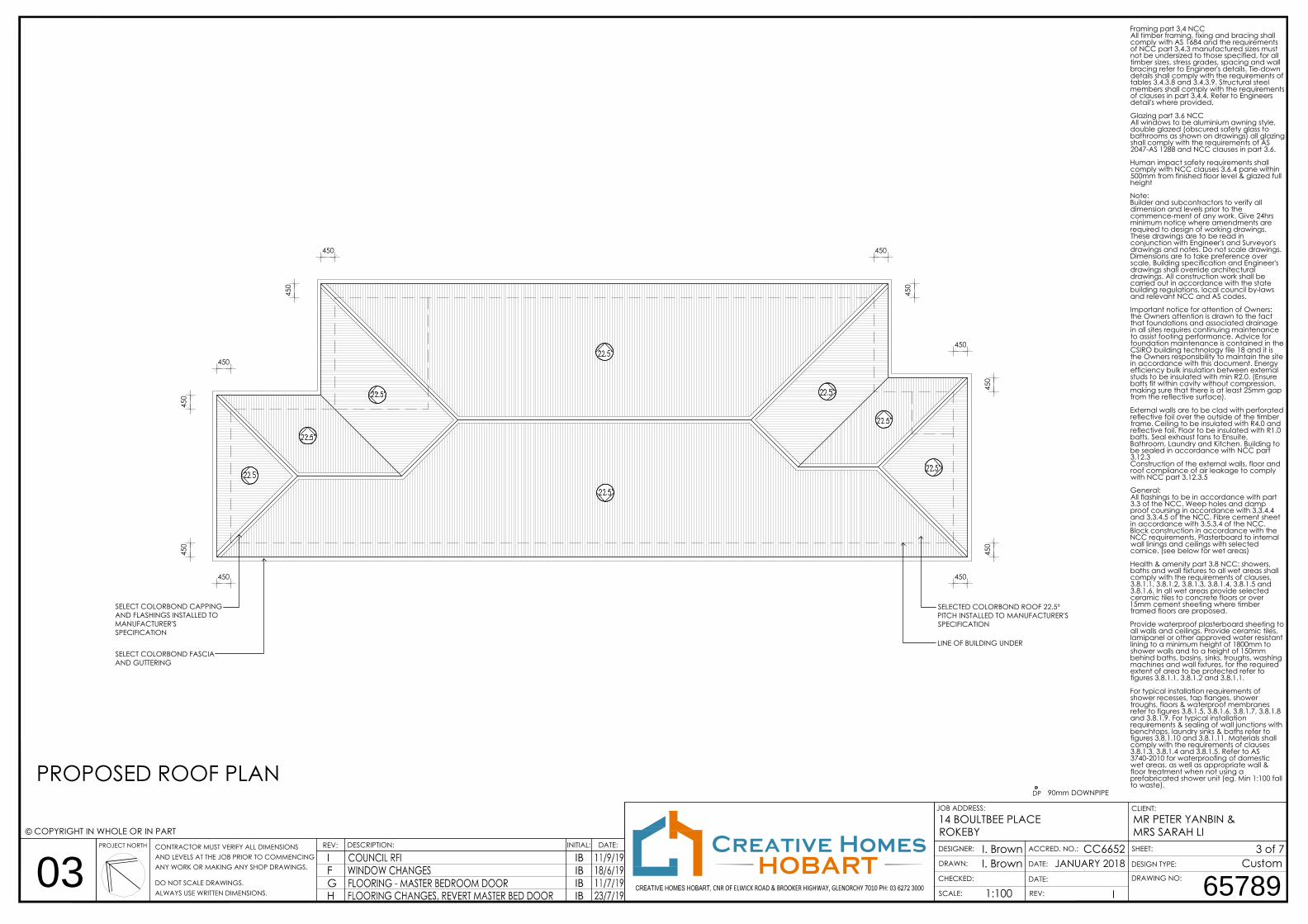
PROPOSED ROOF PLAN
SELECTED COLORBOND ROOF 22.5ºPITCH INSTALLED TO MANUFACTURER'SSPECIFICATION
LINE OF BUILDING UNDER
90mm DOWNPIPEDP
Framing part 3.4 NCCAll timber framing, fixing and bracing shallcomply with AS 1684 and the requirementsof NCC part 3.4.3 manufactured sizes mustnot be undersized to those specified, for alltimber sizes, stress grades, spacing and wallbracing refer to Engineer's details. Tie-downdetails shall comply with the requirements oftables 3.4.3.8 and 3.4.3.9. Structural steelmembers shall comply with the requirementsof clauses in part 3.4.4. Refer to Engineersdetail's where provided.
Glazing part 3.6 NCCAll windows to be aluminium awning style,double glazed (obscured safety glass tobathrooms as shown on drawings) all glazingshall comply with the requirements of AS2047-AS 1288 and NCC clauses in part 3.6.
Human impact safety requirements shallcomply with NCC clauses 3.6.4 pane within500mm from finished floor level & glazed fullheight
Note:Builder and subcontractors to verify alldimension and levels prior to thecommence-ment of any work. Give 24hrsminimum notice where amendments arerequired to design of working drawings.These drawings are to be read inconjunction with Engineer's and Surveyor'sdrawings and notes. Do not scale drawings.Dimensions are to take preference overscale. Building specification and Engineer'sdrawings shall override architecturaldrawings. All construction work shall becarried out in accordance with the statebuilding regulations, local council by-lawsand relevant NCC and AS codes.
Important notice for attention of Owners:the Owners attention is drawn to the factthat foundations and associated drainagein all sites requires continuing maintenanceto assist footing performance. Advice forfoundation maintenance is contained in theCSIRO building technology file 18 and it isthe Owners responsibility to maintain the sitein accordance with this document. Energyefficiency bulk insulation between externalstuds to be insulated with min R2.0. (Ensurebatts fit within cavity without compression,making sure that there is at least 25mm gapfrom the reflective surface).
External walls are to be clad with perforatedreflective foil over the outside of the timberframe. Ceiling to be insulated with R4.0 andreflective foil. Floor to be insulated with R1.0batts. Seal exhaust fans to Ensuite,Bathroom, Laundry and Kitchen. Building tobe sealed in accordance with NCC part3.12.3Construction of the external walls, floor androof compliance of air leakage to complywith NCC part 3.12.3.5
General:All flashings to be in accordance with part3.3 of the NCC. Weep holes and dampproof coursing in accordance with 3.3.4.4and 3.3.4.5 of the NCC. Fibre cement sheetin accordance with 3.5.3.4 of the NCC.Block construction in accordance with theNCC requirements. Plasterboard to internalwall linings and ceilings with selectedcornice. (see below for wet areas)
Health & amenity part 3.8 NCC: showers,baths and wall fixtures to all wet areas shallcomply with the requirements of clauses,3.8.1.1, 3.8.1.2, 3.8.1.3, 3.8.1.4, 3.8.1.5 and3.8.1.6. In all wet areas provide selectedceramic tiles to concrete floors or over15mm cement sheeting where timberframed floors are proposed.
Provide waterproof plasterboard sheeting toall walls and ceilings. Provide ceramic tiles,lamipanel or other approved water resistantlining to a minimum height of 1800mm toshower walls and to a height of 150mmbehind baths, basins, sinks, troughs, washingmachines and wall fixtures, for the requiredextent of area to be protected refer tofigures 3.8.1.1, 3.8.1.2 and 3.8.1.1.
For typical installation requirements ofshower recesses, tap flanges, showertroughs, floors & waterproof membranesrefer to figures 3.8.1.5, 3.8.1.6, 3.8.1.7, 3.8.1.8and 3.8.1.9. For typical installationrequirements & sealing of wall junctions withbenchtops, laundry sinks & baths refer tofigures 3.8.1.10 and 3.8.1.11. Materials shallcomply with the requirements of clauses3.8.1.3, 3.8.1.4 and 3.8.1.5. Refer to AS3740-2010 for waterproofing of domesticwet areas, as well as appropriate wall &floor treatment when not using aprefabricated shower unit (eg. Min 1:100 fallto waste).
SELECT COLORBOND FASCIAAND GUTTERING
SELECT COLORBOND CAPPINGAND FLASHINGS INSTALLED TOMANUFACTURER'SSPECIFICATION
450
450
450
450 450
450
450
450
450
450
450
450
I
IFGH
IBIBIBIB
14 BOULTBEE PLACEROKEBY
MR PETER YANBIN &MRS SARAH LI
JANUARY 2018
65789
CustomDRAWING NO:
DESIGN TYPE:
CLIENT:JOB ADDRESS:
DRAWN:
SHEET:
SCALE: REV:
©
ALWAYS USE WRITTEN DIMENSIONS.DO NOT SCALE DRAWINGS.
ANY WORK OR MAKING ANY SHOP DRAWINGS.AND LEVELS AT THE JOB PRIOR TO COMMENCINGCONTRACTOR MUST VERIFY ALL DIMENSIONS DATE:INITIAL:DESCRIPTION:REV:PROJECT NORTH
CHECKED: DATE:
DATE:
ACCRED. NO.:DESIGNER:Creative HomesHOBART
COPYRIGHT IN WHOLE OR IN PART
I. Brown
1:100
3 of 7I. Brown CC6652
03

5024
0024
0050
C.L R.L 42.05
F.L RL 39.65PORCH/ALFRESCO F.L RL 39.60
C.L R.L 42.05
F.L RL 39.65PORCH/ALFRESCO F.L RL 39.60
SOUTH EASTERN ELEVATION
SOUTH WESTERN ELEVATION
Framing part 3.4 NCCAll timber framing, fixing and bracing shallcomply with AS 1684 and the requirementsof NCC part 3.4.3 manufactured sizes mustnot be undersized to those specified, for alltimber sizes, stress grades, spacing and wallbracing refer to Engineer's details. Tie-downdetails shall comply with the requirements oftables 3.4.3.8 and 3.4.3.9. Structural steelmembers shall comply with the requirementsof clauses in part 3.4.4. Refer to Engineersdetail's where provided.
Glazing part 3.6 NCCAll windows to be aluminium awning style,double glazed (obscured safety glass tobathrooms as shown on drawings) all glazingshall comply with the requirements of AS2047-AS 1288 and NCC clauses in part 3.6.
Human impact safety requirements shallcomply with NCC clauses 3.6.4 pane within500mm from finished floor level & glazed fullheight
Note:Builder and subcontractors to verify alldimension and levels prior to thecommence-ment of any work. Give 24hrsminimum notice where amendments arerequired to design of working drawings.These drawings are to be read inconjunction with Engineer's and Surveyor'sdrawings and notes. Do not scale drawings.Dimensions are to take preference overscale. Building specification and Engineer'sdrawings shall override architecturaldrawings. All construction work shall becarried out in accordance with the statebuilding regulations, local council by-lawsand relevant NCC and AS codes.
Important notice for attention of Owners:the Owners attention is drawn to the factthat foundations and associated drainagein all sites requires continuing maintenanceto assist footing performance. Advice forfoundation maintenance is contained in theCSIRO building technology file 18 and it isthe Owners responsibility to maintain the sitein accordance with this document. Energyefficiency bulk insulation between externalstuds to be insulated with min R2.0. (Ensurebatts fit within cavity without compression,making sure that there is at least 25mm gapfrom the reflective surface).
External walls are to be clad with perforatedreflective foil over the outside of the timberframe. Ceiling to be insulated with R4.0 andreflective foil. Floor to be insulated with R1.0batts. Seal exhaust fans to Ensuite,Bathroom, Laundry and Kitchen. Building tobe sealed in accordance with NCC part3.12.3Construction of the external walls, floor androof compliance of air leakage to complywith NCC part 3.12.3.5
General:All flashings to be in accordance with part3.3 of the NCC. Weep holes and dampproof coursing in accordance with 3.3.4.4and 3.3.4.5 of the NCC. Fibre cement sheetin accordance with 3.5.3.4 of the NCC.Block construction in accordance with theNCC requirements. Plasterboard to internalwall linings and ceilings with selectedcornice. (see below for wet areas)
Health & amenity part 3.8 NCC: showers,baths and wall fixtures to all wet areas shallcomply with the requirements of clauses,3.8.1.1, 3.8.1.2, 3.8.1.3, 3.8.1.4, 3.8.1.5 and3.8.1.6. In all wet areas provide selectedceramic tiles to concrete floors or over15mm cement sheeting where timberframed floors are proposed.
Provide waterproof plasterboard sheeting toall walls and ceilings. Provide ceramic tiles,lamipanel or other approved water resistantlining to a minimum height of 1800mm toshower walls and to a height of 150mmbehind baths, basins, sinks, troughs, washingmachines and wall fixtures, for the requiredextent of area to be protected refer tofigures 3.8.1.1, 3.8.1.2 and 3.8.1.1.
For typical installation requirements ofshower recesses, tap flanges, showertroughs, floors & waterproof membranesrefer to figures 3.8.1.5, 3.8.1.6, 3.8.1.7, 3.8.1.8and 3.8.1.9. For typical installationrequirements & sealing of wall junctions withbenchtops, laundry sinks & baths refer tofigures 3.8.1.10 and 3.8.1.11. Materials shallcomply with the requirements of clauses3.8.1.3, 3.8.1.4 and 3.8.1.5. Refer to AS3740-2010 for waterproofing of domesticwet areas, as well as appropriate wall &floor treatment when not using aprefabricated shower unit (eg. Min 1:100 fallto waste).
BOUN
DA
RY
BUILD
ING ENVEL
OPE
45°
3000
8.5m MAX BUILDING HEIGHT PLANE (SW ELEVATION)
SELECTED ENTRY DOOR
SELECTED COLORBOND ROOFINGINSTALLED TO MANUFACTURER'SSPECIFICATIONS
COLORBOND FASCIA AND GUTTERING
ALUMINIUM FRAMED WINDOWS EXTENT OF EXCAVATIONBATTER MAX 1:1.5
EXTENT OF EXCAVATIONBATTER MAX 1:1.5
SELECTED FACE BRICK
SELECTED FACE BRICK
EXTENT OF EXCAVATIONBATTER MAX 1:1.5
SELECTED GARAGE DOOR
COLORBOND FASCIAAND GUTTERING
ALUMINIUM FRAMEDWINDOWS
OBSCURED SAFETY GLASS
450
450450
CONCRETE DRIVEWAY SLAB TO ENGINEER'S DETAILS
450
450ROO
F PITCH 2
2.5°
ROOF PITCH 2
2.5°
ROOF PITCH 22.5°
I
IFGH
IBIBIBIB
14 BOULTBEE PLACEROKEBY
MR PETER YANBIN &MRS SARAH LI
JANUARY 2018
65789
CustomDRAWING NO:
DESIGN TYPE:
CLIENT:JOB ADDRESS:
DRAWN:
SHEET:
SCALE: REV:
©
ALWAYS USE WRITTEN DIMENSIONS.DO NOT SCALE DRAWINGS.
ANY WORK OR MAKING ANY SHOP DRAWINGS.AND LEVELS AT THE JOB PRIOR TO COMMENCINGCONTRACTOR MUST VERIFY ALL DIMENSIONS DATE:INITIAL:DESCRIPTION:REV:PROJECT NORTH
CHECKED: DATE:
DATE:
ACCRED. NO.:DESIGNER:Creative HomesHOBART
COPYRIGHT IN WHOLE OR IN PART
I. Brown
1:100
4 of 7I. Brown CC6652
04

I
IFGH
IBIBIBIB
14 BOULTBEE PLACEROKEBY
MR PETER YANBIN &MRS SARAH LI
JANUARY 2018
65789
CustomDRAWING NO:
DESIGN TYPE:
CLIENT:JOB ADDRESS:
DRAWN:
SHEET:
SCALE: REV:
©
ALWAYS USE WRITTEN DIMENSIONS.DO NOT SCALE DRAWINGS.
ANY WORK OR MAKING ANY SHOP DRAWINGS.AND LEVELS AT THE JOB PRIOR TO COMMENCINGCONTRACTOR MUST VERIFY ALL DIMENSIONS DATE:INITIAL:DESCRIPTION:REV:PROJECT NORTH
CHECKED: DATE:
DATE:
ACCRED. NO.:DESIGNER:Creative HomesHOBART
COPYRIGHT IN WHOLE OR IN PART
I. Brown
1:100
5 of 7I. Brown CC6652
05

ALL TRUSSES TO BE DESIGNED TOTRUSS MANUFACTURER TO NOTE:
BE SUPPORTED BY ALL EXTERNALWALLS FOR BOTH DEAD ANDWIND LOADS.
2400
C.L R.L 42.05
F.L RL 39.65
FRAMING PART 3.4 BCA
ALL TIMBER FRAMING, FIXING AND BRACING SHALL COMPLY WITH AS 1684AND THE REQUIREMENTS OF BCA PART 3.4.3 MANUFACTURED SIZES MUSTNOT BE UNDERSIZED TO THOSE SPECIFIED, FOR ALL TIMBER SIZES, STRESSGRADES, SPACING AND WALLBRACING REFER TO ENGINEERS DETAILS. TIE-DOWN DETAILS SHALLCOMPLY WITH THE REQUIREMENTS OF TABLES 3.4.3.8 AND 3.4.3.9
STRUCTURAL STEEL MEMBERS SHALL COMPLY WITH THE REQUIREMENTS OFCLAUSES IN PART 3.4.4. REFER TO ENGINEERS DETAILS WHERE PROVIDED.
GLAZING PART 3.6 BCA
ALL WINDOWS TO BE ALUMINIUM AWNING STYLE, DOUBLE GLAZED.(OBSCURED SAFETY GLASS TO BATHROOMS) ALL GLAZING SHALL COMPLYWITH THE REQUIREMENTS OF AS 2047-AS 1288 AND BCA CLAUSES IN PART3.6.
HUMAN IMPACT SAFETY REQUIREMENTS SHALL COMPLY WITH BCA CLAUSES3.6.4 PANE WITHIN 500mm FROM FINISHED FLOOR LEVEL & GLAZED FULLHEIGHT
NOTE:BUILDER AND SUBCONTRACTORS TO VERIFY ALL DIMENSIONS AND LEVELS PRIOR TO THE COMMENCEMENT OF ANY WORK. GIVE 24HRS MINIMUM NOTICEWHERE AMENDMENTS ARE REQUIRED TO DESIGN OF WORKING DRAWINGS. THESE DRAWINGS ARE TO BE READ IN CONJUNCTION WITH ENGINEERS ANDSURVEYORS DRAWINGS AND NOTES. DO NOT SCALE DRAWINGS. DIMENSIONS ARE TO TAKE PREFERENCE OVER SCALE. BUILDING SPECIFICATION ANDENGINEERS DRAWINGS SHALL OVERRIDE ARCHITECTURAL DRAWINGS.
ALL CONSTRUCTION WORK SHALL BE CARRIED OUT IN ACCORDANCE WITH THE STATE BUILDING REGULATIONS, LOCAL COUNCIL BY-LAWS AND RELEVANTBCA AND AS CODES.
IMPORTANT NOTICE FOR ATTENTION OF OWNERS: THE OWNERS ATTENTION IS DRAWN TO THE FACT THAT FOUNDATIONS AND ASSOCIATED DRAINAGE INALL SITES REQUIRES CONTINUING MAINTENANCE TO ASSIST FOOTING PERFORMANCE. ADVICE FOR FOUNDATION MAINTENANCE IS CONTAINED IN THECSIRO BUILDING TECHNOLOGY FILE 18 AND IT IS THE OWNERS RESPONSIBILITY TO MAINTAIN THE SITE IN ACCORDANCE WITH THIS DOCUMENT.
ENERGY EFFICIENCYBULK INSULATION BETWEEN EXTERNAL STUDS TO BE INSULATED WITH MIN R2.0. (ENSURE BATTS FIT WITHIN CAVITY WITHOUT COMPRESSION, MAKING SURETHAT THERE IS AT LEAST 25MM GAP FROM THE REFLECTIVE SURFACE.)EXTERNAL WALLS TO BE CLAD WITH PERFORATED REFLECTIVE FOIL OVER THE OUTSIDE OF THE TIMBER FRAME.CEILING TO BE INSULATED WITH R4.0 AND REFLECTIVE FOIL.FLOOR TO BE INSULATED WITH R1.0 BATTS. SEAL EXHAUST FANS TO ENSUITE, BATHROOM, LAUNDRY AND KITCHEN.BUILDING TO BE SEALED IN ACCORDANCE WITH BCA PART 3.12.3CONSTRUCTION OF THE EXTERNAL WALLS, FLOOR AND ROOF COMPLIANCE OF AIR LEAKAGE TO COMPLY WITH BCA PART 3.12.3.5
GENERAL:ALL FLASHINGS TO BE IN ACCORDANCE WITH PART 3.3 OF THE BCA. WEEP HOLES AND DAMP PROOF COURSING INACCORDANCE WITH 3.3.4.4 AND 3.3.4.5 OF THE BCA. FIBRE CEMENT SHEET IN ACCORDANCE WITH 3.5.3.4 OF THE BCA.
BLOCK CONSTRUCTION IN ACCORDANCE WITH THE BCA REQUIREMENTS. PLASTERBOARD TO INTERNAL WALL LININGS ANDCEILINGS WITH SELECTED CORNICE. (SEE BELOW FOR WET AREAS)
HEALTH & AMENITY PART 3.8 BCA: SHOWERS, BATHS AND WALL FIXTURES TO ALL WET AREAS SHALL COMPLY WITH THEREQUIREMENTS OF CLAUSES, 3.8.1.1, 3.8.1.2, 3.8.1.3, 3.8.1.4, 3.8.1.5 AND IN ALL WET AREAS PROVIDE SELECTED CERAMICTILES TO CONCRETE FLOORS OR OVER 15MM CEMENT SHEETING WHERE TIMBER FRAMED FLOORS ARE PROPOSED.
PROVIDE WATERPROOF PLASTERBOARD SHEETING TO ALL WALLS AND CEILINGS. PROVIDE CERAMIC TILES, LAMIPANEL OROTHER APPROVED WATER RESISTANT LINING TO A MINIMUM HEIGHT OF 1800MM TO SHOWER WALLS AND TO A HEIGHT OF150MM BEHIND BATHS, BASINS, SINKS, TROUGHS, WASHING MACHINES AND WALL FIXTURES, FOR THE REQUIRED EXTENT OFAREA TO BE PROTECTED REFER TO FIGURES 3.8.1.1, 3.8.1.2 AND 3.8.1.1.
FOR TYPICAL INSTALLATION REQUIREMENTS OF SHOWER RECESSES, TAP FLANGES, SHOWER TROUGHS, FLOORS &WATERPROOF MEMBRANES REFER TO FIGURES 3.8.1.5, 3.8.1.6, 3.8.1.7, 3.8.1.8 AND 3.8.1.9. FOR TYPICAL INSTALLATIONREQUIREMENTS & SEALING OF WALL JUNCTIONS WITH BENCHTOPS, LAUNDRY SINKS & BATHS REFER TO FIGURES 3.8.1.10 AND3.8.1.11. MATERIALS SHALL COMPLY WITH THE REQUIREMENTS OF CLAUSES 3.8.1.3, 3.8.1.4 AND 3.8.1.5. REFER TO AS 3740-2010FOR WATERPROOFING OF DOMESTIC WET AREAS, AS WELL AS APPROPRIATE WALL & FLOOR TREATMENT WHEN APREFABRICATED SHOWER UNIT ISN'T USED (EG. MIN 1:100 FALL TO WASTE)
SECTION A-A
SELECTED COLORBOND ROOFINGINSTALLED TO MANUFACTURER'SSPECIFICATIONS
SELECTED KITCHEN JOINERY,SPLASHBACKS, FIXTURES AND FITTINGS
SELECTED FACE BRICKWORK
R2 BULK INSULATION & REFLECTIVEFOIL TO EXTERNAL WALLS
450 EAVES O/HANGFC LINING TO EAVES
CONCRETE SLAB ONAPPROVED FILL BASE TOENGINEER'S DETAILS
SELECTED COLORBONDGUTTERING INSTALLED TOMANUFACTURER'S SPECIFICATIONS
TIMBER ROOF TRUSSES AT 600 CTRS TOMANUFACTURER'S SPECIFICATION
CONCRETE SLABS AND FOOTINGSTO ENGINEER'S DETAILS
EXCAVATION BATTER WITH AGGDRAIN TO ENGINEER'S DETAILS
EXTENT OF EXCAVATION
R4.0 BULK INSULATIONTO CEILING
ALUMINIUM FRAMEDWINDOW INSTALLED TOMANUFACTURER'SSPECIFICATIONS
ROOF PITCH 2
2.5°
PLASTERBOARD LINING TOCEILING, WALLS & CORNICES
I
IFGH
IBIBIBIB
14 BOULTBEE PLACEROKEBY
MR PETER YANBIN &MRS SARAH LI
JANUARY 2018
65789
CustomDRAWING NO:
DESIGN TYPE:
CLIENT:JOB ADDRESS:
DRAWN:
SHEET:
SCALE: REV:
©
ALWAYS USE WRITTEN DIMENSIONS.DO NOT SCALE DRAWINGS.
ANY WORK OR MAKING ANY SHOP DRAWINGS.AND LEVELS AT THE JOB PRIOR TO COMMENCINGCONTRACTOR MUST VERIFY ALL DIMENSIONS DATE:INITIAL:DESCRIPTION:REV:PROJECT NORTH
CHECKED: DATE:
DATE:
ACCRED. NO.:DESIGNER:Creative HomesHOBART
COPYRIGHT IN WHOLE OR IN PART
I. Brown
1:50
6 of 7I. Brown CC6652
06

2100
1800
1200
W1
2100
2100
fgFIXED GLAZINGWINDOW SCHEDULE
Framing part 3.4 NCCAll timber framing, fixing and bracing shallcomply with AS 1684 and the requirementsof NCC part 3.4.3 manufactured sizes mustnot be undersized to those specified, for alltimber sizes, stress grades, spacing and wallbracing refer to Engineer's details. Tie-downdetails shall comply with the requirements oftables 3.4.3.8 and 3.4.3.9. Structural steelmembers shall comply with the requirementsof clauses in part 3.4.4. Refer to Engineersdetail's where provided.
Glazing part 3.6 NCCAll windows to be aluminium awning style,double glazed (obscured safety glass tobathrooms as shown on drawings) all glazingshall comply with the requirements of AS2047-AS 1288 and NCC clauses in part 3.6.
Human impact safety requirements shallcomply with NCC clauses 3.6.4 pane within500mm from finished floor level & glazed fullheight
Note:Builder and subcontractors to verify alldimension and levels prior to thecommence-ment of any work. Give 24hrsminimum notice where amendments arerequired to design of working drawings.These drawings are to be read inconjunction with Engineer's and Surveyor'sdrawings and notes. Do not scale drawings.Dimensions are to take preference overscale. Building specification and Engineer'sdrawings shall override architecturaldrawings. All construction work shall becarried out in accordance with the statebuilding regulations, local council by-lawsand relevant NCC and AS codes.
Important notice for attention of Owners:the Owners attention is drawn to the factthat foundations and associated drainagein all sites requires continuing maintenanceto assist footing performance. Advice forfoundation maintenance is contained in theCSIRO building technology file 18 and it isthe Owners responsibility to maintain the sitein accordance with this document. Energyefficiency bulk insulation between externalstuds to be insulated with min R2.0. (Ensurebatts fit within cavity without compression,making sure that there is at least 25mm gapfrom the reflective surface).
External walls are to be clad with perforatedreflective foil over the outside of the timberframe. Ceiling to be insulated with R4.0 andreflective foil. Floor to be insulated with R1.0batts. Seal exhaust fans to Ensuite,Bathroom, Laundry and Kitchen. Building tobe sealed in accordance with NCC part3.12.3Construction of the external walls, floor androof compliance of air leakage to complywith NCC part 3.12.3.5
General:All flashings to be in accordance with part3.3 of the NCC. Weep holes and dampproof coursing in accordance with 3.3.4.4and 3.3.4.5 of the NCC. Fibre cement sheetin accordance with 3.5.3.4 of the NCC.Block construction in accordance with theNCC requirements. Plasterboard to internalwall linings and ceilings with selectedcornice. (see below for wet areas)
Health & amenity part 3.8 NCC: showers,baths and wall fixtures to all wet areas shallcomply with the requirements of clauses,3.8.1.1, 3.8.1.2, 3.8.1.3, 3.8.1.4, 3.8.1.5 and3.8.1.6. In all wet areas provide selectedceramic tiles to concrete floors or over15mm cement sheeting where timberframed floors are proposed.
Provide waterproof plasterboard sheeting toall walls and ceilings. Provide ceramic tiles,lamipanel or other approved water resistantlining to a minimum height of 1800mm toshower walls and to a height of 150mmbehind baths, basins, sinks, troughs, washingmachines and wall fixtures, for the requiredextent of area to be protected refer tofigures 3.8.1.1, 3.8.1.2 and 3.8.1.1.
For typical installation requirements ofshower recesses, tap flanges, showertroughs, floors & waterproof membranesrefer to figures 3.8.1.5, 3.8.1.6, 3.8.1.7, 3.8.1.8and 3.8.1.9. For typical installationrequirements & sealing of wall junctions withbenchtops, laundry sinks & baths refer tofigures 3.8.1.10 and 3.8.1.11. Materials shallcomply with the requirements of clauses3.8.1.3, 3.8.1.4 and 3.8.1.5. Refer to AS3740-2010 for waterproofing of domesticwet areas, as well as appropriate wall &floor treatment when not using aprefabricated shower unit (eg. Min 1:100 fallto waste).
600
1000
1800
1200
900
1000
1500
1000
1800
1200
1800
1200
OBSCUREDSAFETYGLASS
OBSCUREDSAFETYGLASS
OBSCUREDSAFETYGLASS
600
1000
2100
1200
3050
2100
W2 W3 W4 W5 W6 W7
W8 W9 W10 W11 W12 W13
W14
600
1200
W15
DELETED DELETED
2100
1200
DELETED
I
IFGH
IBIBIBIB
14 BOULTBEE PLACEROKEBY
MR PETER YANBIN &MRS SARAH LI
JANUARY 2018
65789
CustomDRAWING NO:
DESIGN TYPE:
CLIENT:JOB ADDRESS:
DRAWN:
SHEET:
SCALE: REV:
©
ALWAYS USE WRITTEN DIMENSIONS.DO NOT SCALE DRAWINGS.
ANY WORK OR MAKING ANY SHOP DRAWINGS.AND LEVELS AT THE JOB PRIOR TO COMMENCINGCONTRACTOR MUST VERIFY ALL DIMENSIONS DATE:INITIAL:DESCRIPTION:REV:PROJECT NORTH
CHECKED: DATE:
DATE:
ACCRED. NO.:DESIGNER:Creative HomesHOBART
COPYRIGHT IN WHOLE OR IN PART
I. Brown
1:50
7 of 7I. Brown CC6652
07