Embed Size (px)
Citation preview
International Journal of Modern Trends in Engineering and Research
www.ijmter.com e-ISSN No.:2349-9745, Date: 28-30 April, 2016
@IJMTER-2016, All rights Reserved 965
Development and Fabrication of Sheet Metal Cutting Machine Using Pantograph Mechanism.
Mr. Bhor Akshay Ramhari1, Mr. Churi Vishal Madhukar2, Mr. Shinde Avinash Haribhau3, Mr. Chaudhari Bhushan Bhagwant4, Prof. V. P. Chaudhari5
1Department of Mechanical Engineering, MET's IOE, Nashik, [email protected] 2Department of Mechanical Engineering, MET's IOE, Nashik, [email protected]
3Department of Mechanical Engineering, MET's IOE, Nashik, [email protected] 4Department of Mechanical Engineering, MET's IOE, Nashik, [email protected]
5Department of Mechanical Engineering, MET's IOE, Nashik,[email protected]
Abstract- Traditional sheet metal cutting dies were able to cut only on a shape of punch of that particular die and could not generate the replica of already existing object. This kind of machine has large workspace, high sleight and good manoeuvrability; it can be widely used in field sheet metal cutting and wood/metal engraving. However due to its cantilever type structure, the manipulator is inherently not very rigid and thus the link connecting the assembly to the bed is the most vulnerable to failure due to bending load. It is poor in dynamic performance in high speed and heavy duty operations. Hence suitable for light duty and medium speed operations. The mechanical efficiency of pantograph mechanisms and conventional open-chain and closed-chain type manipulators are studied and evaluated using the concept of modified geometric work. The kinematics of 2-DOF pantograph type manipulators are studied and special: mechanisms which simplify the kinematics are introduced. Keywords-Pantograph Mechanism, Degree of Freedom, Links, Sheet Metal Cutting, Dies.
1. INTRODUCTION Traditional sheet metal cutting dies were able to cut only on a shape of punch of that particular die and could not generate the replica of already existing object. This kind of manipulator has large workspace, high sleight and good manoeuvrability; it can be widely used in field sheet metal cutting and wood/metal engraving. However due to its cantilever type structure, the manipulator is inherently not very rigid and thus the link connecting the assembly to the bed is the most vulnerable to failure due to bending load. It is poor in dynamic performance in high speed and heavy duty operations. Hence suitable for light duty and medium speed operations. The mechanical efficiency of pantograph mechanisms and conventional open-chain and closed-chain type manipulators are studied and evaluated using the concept of modified geometric work. The kinematics of 6-DOF pantograph type manipulators are studied and special: mechanisms which simplify the kinematics are introduced. [1] 1.1 Problem Statement Now a days for cutting of metal sheet of any complex shapes required die of that shape. From that die getting only one shape which is shape of punch of die. If there is need of only few shapes it is
International Journal of Modern Trends in Engineering and Research (IJMTER) Volume 3, Issue 4, [April 2016] Special Issue of ICRTET’2016
@IJMTER-2016, All rights Reserved 966
not affordable to purchase die. To overcome this problem this we have been developing and fabricating pantograph sheet metal cutting machine for cutting of sheet metal up to of 1-2mm thickness of any complex shape. Hence this is very good tool to cut sheet of any complex shapes.
1.2 Objectives The pantograph mechanism is used to design and fabricate a sheet metal cutting machine
which could traverse on any contour provided that stylus is moved on the same on any already existing drawing on paper.
Using such kind of manipulator we can generate the de-scaled replica of the object or we can say it to be a copying machine which can be employed in batch production with economical production/machining cost.
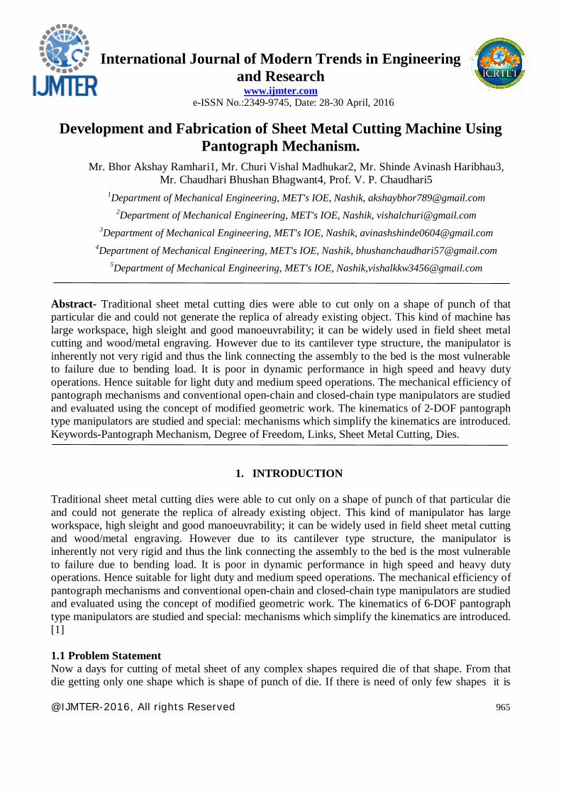
1.3 Methodology The methodology adopted used of the standard pantograph mechanism which containing 4 links of mild steel . The advantage of this is that it has 3 DOF and each link having relative motion with respect to each other. So that stylus and tool can move in all direction for cutting of any complex shape. Initially the frame design is adopted from an already existing pantograph mechanism and minor changes are made to suite our purpose, the reducing and increasing of scale of an object. The quarter hp motor is being to used on which reamer tool will be mounted for cutting operation.
Figure 1 : Flow chart of methodology
II. LINKS A link is a resistant body that constituents the part of the machine connecting other parts which have motion relative to it. e.g. A slider crank mechanism of an IC engine consist of 4 links that is frame, crank, connecting rod and slider. [2]
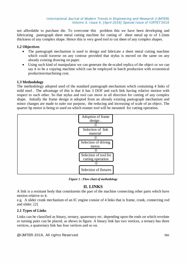
2.1 Types of Links Links can be classified as binary, ternary, quaternary etc. depending upon the ends on which revolute or turning pairs can be placed, as shows in figure. A binary link has two vertices, a ternary has three vertices, a quaternary link has four vertices and so on.
Adoption of frame design .
Selection of link material.
Selection of driving motor.
Selection of tool for cutting operation.
Selection of fixtures
International Journal of Modern Trends in Engineering and Research (IJMTER) Volume 3, Issue 4, [April 2016] Special Issue of ICRTET’2016
@IJMTER-2016, All rights Reserved 967
(a) Binary Link (b)Ternary Link (c) Quaternary Link
Figure 2: Types of Links.
2.2 Degree of Freedom An unconstrained rigid body moving in space can describe the following independent motions. 1. Translational motions along any three mutually perpendicular axes x, y and z. 2. Rotational motions about these axes. Degree of freedom of a pair is defined as the number of independent relative motions, both translation and rotational, a pair can have. Degree of freedom = 6 - Number of restraints.
2.3 Kutzbach Criterion The Kutzbach Criterion for determining number of Degree of Freedom(DOF) is given by, F = 3 (N-1) - 2P1 - P2 Where , F= Number of DOF. N= Total Numbers of link in mechanism. P1= Number of lower pair. P2= Number of higher pair. For Pantograph mechanism, N = 5 , P1 = 5 , P2 = 0 F = 3 ( 5 - 1 ) - 2 * ( 5 ) - 0 F= 2 Degree of Freedom Pantograph is found to be 2. [4]
III. PANTOGRAPH
This is mechanism to produce the path traced out by a point on enlarged or reduced scale. Fig. shows the line diagram of a pantograph in which AB=CD, BC=BD and ABCD is always a parallelogram. OQP is straight line. Point P describes a path similar to that described by Q. The pantograph is used as a copying mechanism.

International Journal of Modern Trends in Engineering and Research (IJMTER) Volume 3, Issue 4, [April 2016] Special Issue of ICRTET’2016
@IJMTER-2016, All rights Reserved 968
(a) Original Position (b)Displaced Position
Figure 3: Pantograph.
Proof :- Triangles OAQ and OBP are similar because ∠ BOP is common. ∠ AOQ= ∠ BOP are corresponding angles as AQ || BP.
Hence, BPAQ
OPOQ
OBOA
........... (i)
In the displaced position shown in fig. as all links are rigid, B1O=BO, D1A1=DA, A1O=AO P1B1=PB, B1A1=BA, A1Q1=AQ And
Hence, 11
11
1
1OA PBQA
OB ..............(ii)
As A1 B1 C1 D1 is a parallelogram, A1D1 || B1C1, i.e. A1Q1 || B1P1. OQ1P1 is again a straight line so that ∆ QA1Q1 and OB1P1 are similar. From eq. (i) and (ii), we get
1
1
OPOQ
OPOQ
because OA=OA1 and OB=OB1.
Hence, QQ1 is similar to PP1 or they are parallel. The pantograph is used in geometrical instruments in the manufacture of irregular objects, to guide cutting tools and as indicator rig for cross-head. [2] 3.1 Dimensions of Mechanism
1
1
1
1OA OPOQ
OB
International Journal of Modern Trends in Engineering and Research (IJMTER) Volume 3, Issue 4, [April 2016] Special Issue of ICRTET’2016
@IJMTER-2016, All rights Reserved 969
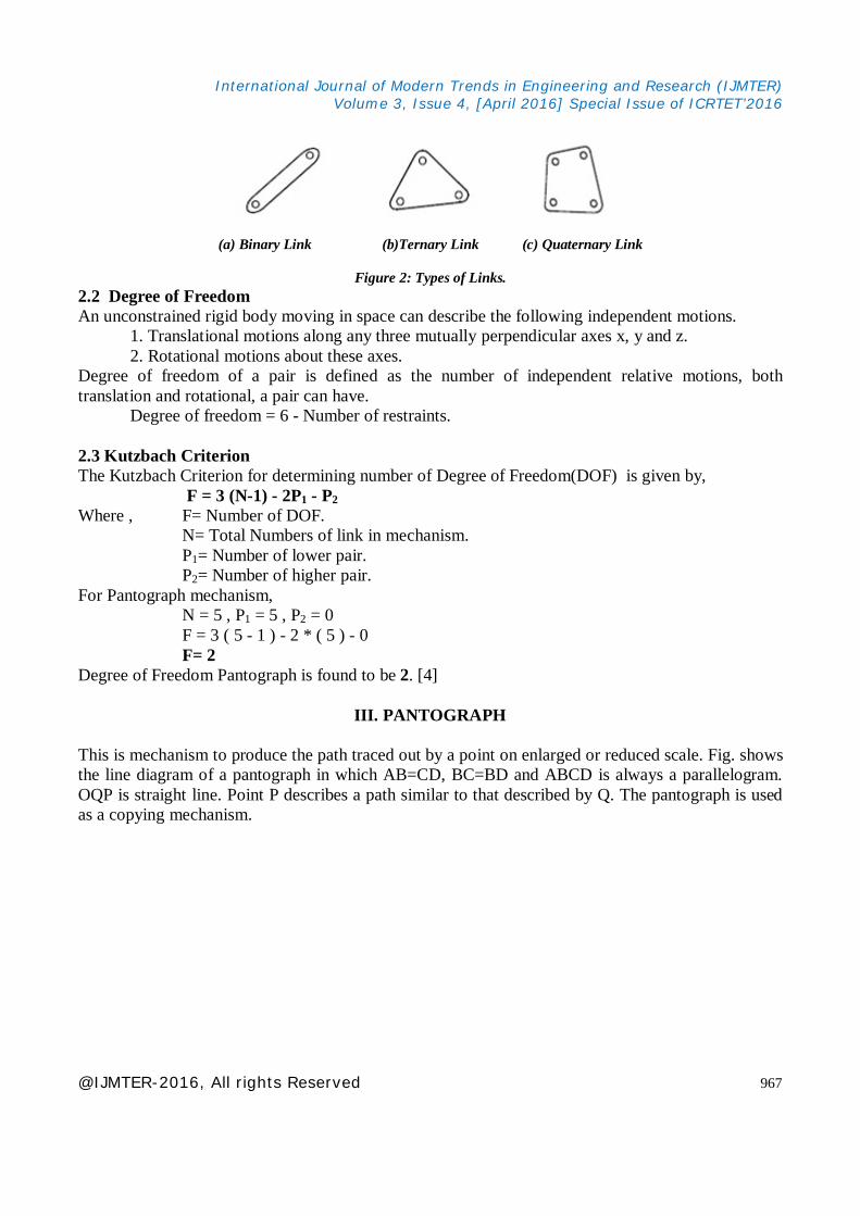
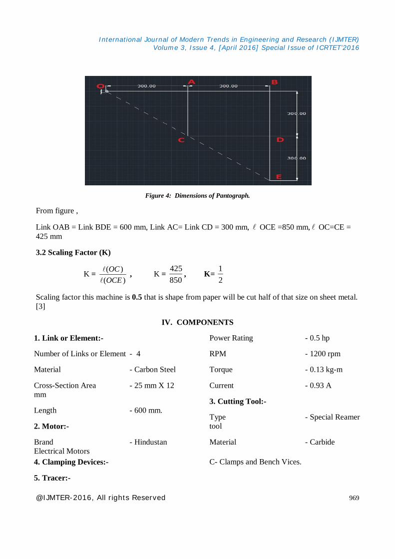
Figure 4: Dimensions of Pantograph.
From figure ,
Link OAB = Link BDE = 600 mm, Link AC= Link CD = 300 mm, OCE =850 mm, OC=CE = 425 mm
3.2 Scaling Factor (K)
K = )(
)(OCEOC
, K =
850425
, K= 21
Scaling factor this machine is 0.5 that is shape from paper will be cut half of that size on sheet metal. [3]
IV. COMPONENTS
1. Link or Element:-
Number of Links or Element - 4
Material - Carbon Steel
Cross-Section Area - 25 mm X 12 mm
Length - 600 mm.
2. Motor:-
Brand - Hindustan Electrical Motors
Power Rating - 0.5 hp
RPM - 1200 rpm
Torque - 0.13 kg-m
Current - 0.93 A
3. Cutting Tool:-
Type - Special Reamer tool
Material - Carbide
4. Clamping Devices:- C- Clamps and Bench Vices.
5. Tracer:-

International Journal of Modern Trends in Engineering and Research (IJMTER) Volume 3, Issue 4, [April 2016] Special Issue of ICRTET’2016
@IJMTER-2016, All rights Reserved 970
Tracer is the simple pen like component. It is used to trace the drawings from paper to cut shape of that drawing on the sheet metal.[5]
VI. APPLICTION
Mainly the pantograph sheet metal cutting machine used for the cutting the metal sheet in various shape by tracing the drawing which is already on the paper.
CONCLUSION
Now a days for cutting of metal sheet of any complex shapes required die of that shape. From that die getting only one shape which is shape of punch of die. If there is need of only few shapes it is not affordable to purchase die. To overcome this problem we have been developing and fabricating pantograph sheet metal cutting machine. This machine complete the following objectives.
The pantograph mechanism is used to cut the sheet of metal of various size and shape up to 1 to 2 mm thickness sheet.
Using such kind of machine we can cut various size on sheet by tracing already existing shapes of the object on the paper with the help of tracer.
FUTURE SCOPE
This machine can be used in metal engraving industries or wood carving industries to copy the engraved wooden design.
At the end-effecter we can replace the cutter by a welding torch or a plasma cutter to perform the desired typical operation with very ease and accuracy.
This Machine can be made fully automatic by connecting tracer point to CNC machine's arm.
REFERENCES [1] http://www.wikipedia.org/wiki/Pantograph [2] Singh Sadhu ," Theory of Machines Second edition ,Pearson education Publication, May 2010". [3] Verma Mahendra and Abrar Ahmad, "The Mechanism and Kinematics of a Pantograph Milling Machine,2013" [4] Ballaney P. L."Theory of machines and Mechanisms, Khanna Publication, May 2011" [5] Norton R. L. "Kinematics and Dynamics of Machinery, Tata McGraw-Hill Publiction, June 2012 "


