Embed Size (px)
Citation preview
Full Terms & Conditions of access and use can be found athttps://www.tandfonline.com/action/journalInformation?journalCode=uhvc21
Science and Technology for the Built Environment
ISSN: 2374-4731 (Print) 2374-474X (Online) Journal homepage: https://www.tandfonline.com/loi/uhvc21
Development and application of hardware-in-the-loop simulation for the HVAC systems
Zhimin Du, Xinqiao Jin, Yonghua Zhu, Yijun Wang, Wenbin Zhang & ZhijieChen
To cite this article: Zhimin Du, Xinqiao Jin, Yonghua Zhu, Yijun Wang, Wenbin Zhang &Zhijie Chen (2019) Development and application of hardware-in-the-loop simulation for theHVAC systems, Science and Technology for the Built Environment, 25:10, 1482-1493, DOI:10.1080/23744731.2019.1649462
To link to this article: https://doi.org/10.1080/23744731.2019.1649462
Accepted author version posted online: 18Sep 2019.Published online: 02 Oct 2019.
Submit your article to this journal
Article views: 129
View related articles
View Crossmark data

Development and application of hardware-in-the-loopsimulation for the HVAC systems
ZHIMIN DU, XINQIAO JIN�, YONGHUA ZHU, YIJUN WANG, WENBIN ZHANG and ZHIJIE CHEN
School of Mechanical Engineering, Shanghai JiaoTong University, 800 Dongchuan Road, Shanghai, China
The hardware-in-the-loop (HIL) employs the real controller and true signal transmission, which is efficient to test control algorithmsfor the situation that is inconvenient to conduct experiments. The design method of hardware-in-the-loop is presented for buildings, inwhich the HVAC system is simulated while the control system including controllers, A/D and D/A modules are real. The controllersembedded with control algorithms are integrated with the simulation of HVAC system. The HVAC HIL test platform is constructedso as to evaluate the candidate control strategies. The feature of HVAC HIL test platform is compared with the pure TRNSYS basedsimulation. The comparison tests show that pure simulation doesn’t match the true control process while the HIL platform does andprovides the credible control response. With real signal transmission and controllers, the control algorithms can be testedauthentically. Moreover, the fault detection and diagnosis (FDD) models using basic and improved principal component analysis(PCA) are evaluated in HVAC HIL platform. Through HIL tests, the unobservable application problem of basic PCA model isdiscovered. An improved wavelet-PCA model is developed, which has the satisfied efficiency to detect the various biases of sensors.
Introduction
In the modern buildings, the HVAC system contributesabout 40% of total energy consumption in the buildings(Ning and Zaheeruddin 2010). Various methods are devel-oped to reduce the energy consumption of HVAC systems.Retrofitting the operation schemes is one popular way,which usually does not involve much hardware modificationbut the control strategies. Therefore, it is convenient to con-duct the retrofitting and the cost is relatively low. Generally,there are two ways to retrofitting the operation scheme. Oneis to complement the optimal algorithm into it, which aimsto optimize the operation level of HVAC system. The otheris to integrate the fault detection and diagnosis (FDD) algo-rithm, which aims to ensure the reliability operation so as toavoid wasting energy caused by faults.
Optimal control is the most widely used approach toimprove the operation efficiency. Wang et al. (1998) studiedthe control of HVAC system in large building in 1990s anddeveloped the optimal control strategies for the multi-chiller
system in the building. After that, Wang and Jin (2000) intro-duced the optimal algorithm of GA into the optimal control ofVAV system’s airside. Fong et al. (2006) applied evolutionaryprogramming to predict the set point of chilled water.Mossolly et al. (2009) developed a control strategy with a GAalgorithm for the building's multi-zone air condition system.The performance using the GA strategy was compared withthat using traditional strategy. In recent years, some newlydesigned optimization methods have been used in the controlof HVAC system, e.g., Coelho et al. (2014) applied the differ-ential cuckoo search approach to solve the optimal multi-chillerloading problem in HVAC system.
As to fault diagnosis based approaches for the energy sav-ings of operation, Rossi and Braun (1997) investigated thesmall/medium size air conditioning systems. The statisticalrules based diagnosis logic was developed and applied in thebuildings. Kim et al. (2008) presented the detection and diag-nosis models using statistical probability analysis and experi-mental rules for the residential heat pumps. Some FDDmethods of HVAC system focused on the faults of sensors andactuators in the control loop. Yoshida et al. (2001) presentedonline detection and diagnosis model for damper faults inVAV systems. Wang and Wang (2002) developed a robustfault diagnosis and validation strategy for the bias of tempera-ture sensors and flow meters in a central chilling plant basedon the first law of thermodynamics. Lee et al. (2004) devel-oped the general neural networks for the faults of actuator andtemperature sensors in the air handling unit. Schein et al.(2006) designed a series of expert rules to assess the
Received May 2, 2019; accepted July 16, 2019Zhimin Du, PhD, is an Associate Professor. Xinqiao Jin,PhD, is a Professor. Yonghua Zhu, is a PhD Student. YijunWang, is a PhD Student. Wenbin Zhang, is a MSc Student.Zhijie Chen, is a MSc Student.*Corresponding author email: [email protected] versions of one or more of the figures in the article canbe found online at www.tandfonline.com/uhvc.
Science and Technology for the Built Environment, (2019) 25, 1482–1493Copyright # 2019 ASHRAE.ISSN: 2374-4731 print / 2374-474X onlineDOI: 10.1080/23744731.2019.1649462

performance of an air handling unit. The faults including biasesof temperature sensor, damp stuck, and controller programmingerrors can be detected successfully. Xiao et al. (2009) enhancedthe capability of the PCA-based method for sensor faults in aVAV system. The expert knowledge based multivariable modelwas developed and applied.
Recently, data mining and machine learning are rapidlydeveloped and used for the diagnosis purpose in the buildingHVAC field. Fan et al. (2010) developed a self-adaptive sen-sor fault detection and diagnosis strategy for air handlingunits. Zhu et al. (2012) designed a neural network pre-proc-essed by wavelet and fractal method. This model was usedto detect the sensor faults in air handling units. Du et al.(2014) presented the dual neural network strategy to detectthe faults of sensors in the control loop of air handling units.Zhao et al. (2013) developed the Bayesian belief networkbased models to diagnose the commonly occurring faults inthe centrifugal chilled water system. Xiao et al. (2014)improved the Bayesian network model and developed robuststrategies to diagnose the faults in variable air volume sys-tems. Kim and Braun (2015) presented the virtual refrigerantsensor model to diagnose the refrigerant charge faultsincluding undercharge and overcharge for the air condition-ing systems in small buildings.
However, most of these control or diagnosis schemes havethe possibility of improper configuration or mismatching inreal situations. It results in the limited control performance ordiagnosis efficiency when the proposed control strategy is usedin the actual applications. The main reason is lacking efficienttest platform for the development of control strategies.
Generally, the commonly used test platforms in the HVACindustry can be classified into two kinds. One kind is based onthe actual target building and HVAC system, the other kind isbased on simulation. The actual test platform may cover all ofthe complexity of building HVAC system, so it can make acomprehensive evaluation of the tested operation scheme. Butthe cost of testing on actual test platform is expensive, the riskis inevitable, and the test duration is usually long. Most oper-ation schemes do not have the opportunity to be tested onactual test platform. As to the simulation based control devel-opment, on the other hand, the test cost is relatively cheap andthere is no risk for operation. The test duration is relativelyshort. Unfortunately, the pure simulation based control devel-opment doesn’t match the real control process, although itsphysical simulation for HVAC system is detailed enough. Thedeveloped algorithms based on pure simulation, consequently,no matter optimal control or FDD models, usually have thelimited efficiencies during the real applications.
To combine the advantage of the actual and simulationtest platform, hardware in the loop (HIL) test technique isproposed. In the HIL test platform, part components areselected in the form of real hardware, while others are simu-lated by the computer. Actually, the HIL test platforms arestill not commonly used in the field of building HVAC butwidely employed in some industry application such as auto-mobile. With a proper design, it is possible to build a HILtest platform which is reliable, inexpensive, safety and time-effective for testing the HVAC system’s operation scheme.Xu et al. (2004) designed a low cost interface between thesimulation and real control system and presented a HIL
Fig. 1. The schematic diagram of water side in HVAC system.
Volume 25, Number 10, November-December 2019 1483

simulation environment for HVAC control strategies’ testing.Michalek et al. (2005) developed a HIL simulation for theair conditioner controller of automobiles with a combinedHVAC and passenger compartment models. Rhee et al.(2011) presented an evaluation method for a hydronic radi-ant heat system with hardware hydronic network and controlcomponents in its HIL test platform.
This article presents the design method of HIL test plat-form for building a HVAC system. The HVAC HIL testplatform was established and its feature is compared withTRNSYS based simulation. As the application examples, theoperation schemes of both PID control for zone temperatureand FDD for sensor measurements are tested and retrofittedon the HVAC HIL test platform. Employing the HVAC HILtest platform, the limitation of basic FDD model using prin-cipal component analysis (PCA) is analyzed. With HIL tests,the improved FDD model using wavelet-PCA is developed.The basic PCA and improved wavelet-PCA models are eval-uated using pure simulation and HIL experiments,respectively.
HIL test platform for the building HVAC system
The involved HVAC systemFigure 1 shows the schematic diagram of water side in theHVAC system. It is a primary-secondary chilled water sys-tem, including two cooling towers, four chillers, elevenpumps, and four air handling units. Figure 1 also depicts thecontrol loops of the water side in the HVAC system. Thecooling water temperature is controlled by adjusting the two-way valve. The chilled water supply temperature of eachchiller is controlled by adjusting the capacity of the chiller.The chiller sequence is modulated by the supervisory con-troller according to the cooling load condition. The multiplecooling towers are modulated to maintain the towers at thesame load as far as possible. The pressure drop on the
bypass water pipe is controlled by the two-way valve. Thewater pressure drop in the secondary water loop is controlledby adjusting the speed of the pump through the inverter. Thesupply air temperature of the air handling unit is controlledby the two way valve of chilled water.
Figure 2 presents the schematic diagram of the air side inthe HVAC system, which is the variable air volume system.Only one air handling unit with eight VAV terminals isdepicted in Figure 2, since the schematic diagrams of theother three air handling units are the same. In the air side,the supply air static pressure of air handling unit is con-trolled by adjusting the speed of supply air fan. The flowrate of outdoor air is maintained at the setpoint throughadjusting the opening of the outdoor air damper.
The requirements for the HIL test platformThe requirements for the HIL test platform are specifiedas below.1. For space and cost consideration, the building and the
components of a HVAC system, excepting its controlloop components, are simulated on the computer inthis article.
2. To represent the complexity of control loops, actualcontrollers are selected and used in the HVAC HIL testplatform. Also, to indicate the operation status of theHVAC system, the digital displays for parameters andstatus indicator lights for equipment are all installed onthe HIL test platform.
3. The HVAC HIL test platform should be compatible fordifferent operation schemes via changing the operationscheme script embedded into the controllers.
The design of HIL test platformTo satisfy the requirements of HVAC HIL test platform,TRNSYS, MATLAB, and LabVIEW are employed todevelop its software part. TRNSYS is used to do thedynamic simulation for building and HVAC system. Its
Fig. 2. The schematic diagram of air side in HVAC system.
1484 Science and Technology for the Built Environment

TRNBuild is used to simulate the thermal physics of multi-zone building. With the user-defined TRNSYS models(Wang and Jin 2000), the building HVAC system simulatoris constructed and its operation under various weather condi-tions is simulated. MATLAB is intended for the numericalcomputing for control and diagnosis purpose. Under theMATLAB environment, it is convenient to develop the con-trol algorithms of HVAC system and embed them into thecontroller of HIL test platform. The various optimal controlstrategies can be tested in this HIL platform through chang-ing the setpoint of controlled variables or on-off status ofequipment in Figure 3. LabVIEW is a graphical languageand it is commonly used for data acquisition (DAQ) anddigital control system (DCS). Through the communicationfunction of LabVIEW, the real PID controllers and PLC areintegrated with the HVAC simulator through A/D (analog-to-digital) and D/A (digital-to-analog) modules. The real-time test monitor of the HVAC HIL platform is also devel-oped using the LabVIEW programming environment.
Figure 3 depicts the logic of the HIL test platform. Itshows the connections of TRNSYS, MATLAB, andLabVIEW programs in the HIL test platform. The LabVIEWprogram connects the hardware components of A/D module,D/A module, and programmable logic controller (PLC). Itfeeds them with the input signals and collects their outputsignals. The TRNSYS program runs simulation of the build-ing and HVAC system (Wang and Jin 2000). The MATLABprogram runs the embedded operation scheme such as theoptimal control strategy and fault diagnosis logic, and is theconnection between the LabVIEW and the TRNSYS pro-gram. It has the interfaces with both of them. Through thoseinterfaces, the MATLAB program transfers the information
between TRNSYS and LabVIEW, including output signalsof the controllers, the simulation results of HVAC system,set values of controllers and on-off states of the equipment.The MATLAB program can also operate according to theembedded operation strategy (algorithm), and generate theinput for the TRNSYS software’s simulation of next-timestep. The flow chart of the MATLAB and TRNSYS pro-grams in the HIL test platform during one time step is illus-trated in Figure 4.
Figure 5 shows the hardware arrangement of the HIL testplatform, including those hardware components in the con-trol loops and two computers. Since the TRNSYS programhas a high computation cost when simulating the buildingand its HVAC system, one computer, named as simulationcomputer, is intended for running the TRNSYS program.The other computer, named as control computer, is used torun the LabVIEW and MATLAB programs and connectwith those hardware components in the control loops. Totransfer and exchange the data between MATLAB andTRNSYS program, the two computers in the HIL test plat-form are also connected by TCP/IP protocol.
The A/D module, D/A module and PLC of HIL test plat-form are installed in the electrical cabinet (Figure 6a). Thehardware controllers are mounted on a board named as thetest board. All the controllers on the water side of HVACsystem are set on the test board. To reduce the cost of theHIL test platform, only one air handling unit and its VAVterminals are configured with hardware controllers on thetest board. While the other three air handling units and theirair sides are simulated by TRNSYS. Digital displays andindicator lights are also configured and installed on the testboard to show the real-time state of the HVAC system
Fig. 3. The logic of HIL test platform for building HVAC system.
Volume 25, Number 10, November-December 2019 1485

during the tests. The overview of HIL test platform is shownin Figure 6.
The features of building HVAC HIL test platform
The characteristic of real controllersThe controller simulated by the computer may have thesame algorithm as the real controller, but it is difficult tosimulate the influence of the field environment, such as thedelay of communication and the electromagnetic interfer-ence. With those real controllers, the HIL test platform canbe used to test the operation scheme of the HVAC systemand make them more realistic. The structure of controller-in-the-loop is illustrated in Figure 7, which shows the signal
transferring and exchanging between the real controller andcomputer simulation.
As an example, the control of zone temperature is testedon the HIL platform. For each zone, the VAV terminal ismodulated through comparing the current zone temperatureand its required setpoint. The setpoint of zone temperaturemay be set by the manual or optimal strategies. In this test,it is set to be constant so as to simplify the comparison andreduce the disturbing factors.
The maintained zone temperatures using simulated con-troller (pure TRNSYS simulation) and real controller(HVAC HIL platform) are compared in Figure 8. It shouldbe noted that the two tests are carried out under the sameoperation condition of HVAC system. Although the same
Fig. 4. The flow chart of MATLAB and TRNSYS programs in HIL test platform.
Fig. 5. The hardware arrangement of HIL test platform.
1486 Science and Technology for the Built Environment

PID (proportional integral differential) parameters are usedin the pure simulation and HIL test, the curves of zone tem-perature and controller output are never to be the same.Figure 8 clearly shows the difference of control resultbetween the real controller and the controller simulated byTRNSYS. The results show that the pure simulated control-ler doesn’t match the true control process. Although theyhave the same proportional, integral, and differential parame-ters, the algorithm of the real controller is still different withthe simulated one at the other aspects of dead band, filtercoefficient, and rising time etc. Actually, the simulated con-troller can be viewed to provide the ideal control response,
which doesn’t include the complex factors of true controlprocess such as the analog signal, its transferring and timedelay etc. Consequently, the simulated controller cannot givethe correct or reasonable control response.
The result of Figure 8 indicates that the control parame-ters obtained from the simulation should be adjusted or re-tuned on the HIL test platform or real HVAC system.Actually, the pure simulation can hardly match the real ana-log signal transferring process, which may influence theaccuracy and reliability of proposed control strategy duringits application. The HIL can provide the true control processbecause of its real analog signal transferring and control
Fig. 6. The overview of HIL test platform. (a) Electrical control system (b) HVAC HIL experimental platform.
Fig. 7. The signal exchange flowchart between controller and simulator.
Volume 25, Number 10, November-December 2019 1487

components. Consequently, the control and FDD strategiesafter HIL tests may be more robust in the real applications.
The repeatability verification testsAs the HIL test platform adopts the real controllers whichmay be disturbed by the electromagnetic interference of theenvironment, the results from the two tests of identical oper-ation scheme under the same configuration of test platformcannot be strictly the same. But such difference is expectedto be small, and it is acceptable for testing the various oper-ation schemes of HVAC system. Still taking the control ofzone temperature as an example, with the same configurationof test platform and the same parameters of PID controller,the results of two tests are shown in Figure 9. It can be seenthat the zone temperatures under the two tests are over-lapped. The controller outputs of the tests are almost
overlapped with the slight difference, which is acceptable inthe testing operation schemes.
Application: Development and evaluation for variousFDD models
The HIL test platform can be used as the development andevaluation tool for the operation schemes of HVAC systems.Different operation schemes can be tested and evaluated,including the optimal strategy and FDD algorithms proposedfor the HVAC system. Since the hardware controllers andanalog signals are involved in the HIL test platform, theoperation process on the HIL platform is more realistic thanthat on the simulation platform. This section presents anapplication of testing the candidate FDD model for the sen-sors in the air handling unit (Du et al. 2007). The FDD
Fig. 8. Comparison between pure simulation and HIL test. (a) Zone temperature, (b) PID controller output.
Fig. 9. Repeatability verification under the same control parameters and configuration. (a) Zone temperature, (b) PID controller output.
1488 Science and Technology for the Built Environment

Fig. 10. Fault detection logic using the basic PCA model.
Fig. 11. Tests of the basic PCA detection model. (a) Fixed bias=1�C, (b) Fixed bias=0.5�C, (c) Fixed bias=0.4�C, (d)Fixed bias=0.3�C.
Volume 25, Number 10, November-December 2019 1489
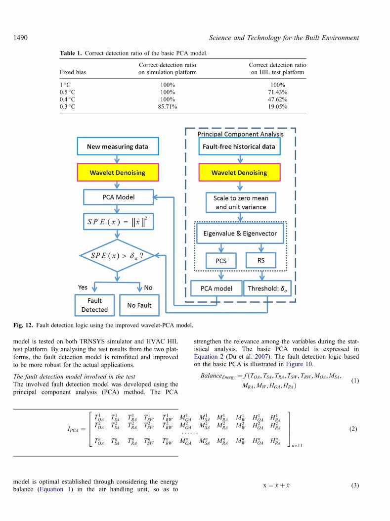
model is tested on both TRNSYS simulator and HVAC HILtest platform. By analysing the test results from the two plat-forms, the fault detection model is retrofitted and improvedto be more robust for the actual applications.
The fault detection model involved in the testThe involved fault detection model was developed using theprincipal component analysis (PCA) method. The PCA
model is optimal established through considering the energybalance (Equation 1) in the air handling unit, so as to
strengthen the relevance among the variables during the stat-istical analysis. The basic PCA model is expressed inEquation 2 (Du et al. 2007). The fault detection logic basedon the basic PCA is illustrated in Figure 10.
BalanceEnergy ¼ f ðTOA,TSA, TRA,TSW , TRW ,MOA,MSA,
MRA,MW ,HOA,HRAÞ(1)
x ¼ x̂ þ ~x (3)
Table 1. Correct detection ratio of the basic PCA model.
Fixed biasCorrect detection ratioon simulation platform
Correct detection ratioon HIL test platform
1 �C 100% 100%0.5 �C 100% 71.43%0.4 �C 100% 47.62%0.3 �C 85.71% 19.05%
Fig. 12. Fault detection logic using the improved wavelet-PCA model.
IPCA ¼T1OA T1
SA T1RA T1
SW T1RW M1
OA M1SA M1
RA M1W H1
OA H1RA
T2OA T2
SA T2RA T2
SW T2RW M2
OA M2SA M2
RA M2W H2
OA H2RA
� � � � � �TnOA Tn
SA TnRA Tn
SW TnRW Mn
OA MnSA Mn
RA MnW Hn
OA HnRA
26664
37775n�11
(2)
1490 Science and Technology for the Built Environment

SPE xð Þ ¼ �xj jj j2 � da (4)
In Equation 3, x represents the measurement vector ofstudied system, which can be decomposed into two parts. x̂is the modelled part that represents the projection on theprincipal component subspace (PCS) showing the fault-freeconditions. � x is the un-modelled part on the residual sub-space (RS) indicating the abnormities or faults. SPE inEquation 4 is the abbreviation of squared prediction errorand da is the detection threshold.
Comparison tests of fault detection modelBefore application, the PCA model is trained using the fault-free operation data. The fault-free operation data of theHVAC system on Shanghai’s typical summer day is gener-ated by TRNSYS simulation and HIL test platform, respect-ively. Under the fault-free condition, the operation databetween 10:00 and 16:00 are selected to train the PCAmodel under the different platforms. The detection thresh-olds da using pure simulation and HIL platform are 2.0489and 1.4617, respective. During the tests, the HVAC systemoperates under the similar weather and load condition.Various magnitudes of fixed bias are emulated to the supplyair temperature sensor, which are conducted on simulationand HIL test platform respectively. The tested fixed biasesof supply air temperature sensor include 1 �C, 0.5 �C, 0.4 �Cand 0.3 �C.
The comparison results are shown in Figure 11. Thedetection results on the simulation test platform are differentwith those on the HIL test platform. The correct detectionratio CDR is calculated using Equation 5.
CDR ¼ Detected Fault Samples
Total Fault Samples� 100% (5)
The correct detection ratios under the various fault scen-arios are listed in Table 1. It can be seen that the correctdetection ratio are high when the tests are carried out on thepure simulation platform. As for the HIL test platform, how-ever, the detection ratio is not satisfied and decreased greatlyfor the small bias magnitudes. The results prove that the truecontrol process is more complex than the simulated one, andmay affect the proposed detection model greatly. It indicatesthat the efficiency of FDD models may be not as satisfied asthe expectation of its developers, when they are used in thereal applications.
Retrofitting the fault detection modelThe HIL test platform for the building HVAC systems canbe used to retrofit and improve the FDD models developed.In real applications, the analog signals are sensitive to theelectromagnetic interference, which is possibly caused bythe environment, which was observed on the HIL test plat-form in the former section. Li and Wen (2014) presented thewavelet-PCA algorithm to diagnose the faults of air dampersand coil valves in air handling unit. The wavelet was usedto process the site-data so as to improve the robustness ofthe detection method. Consequently, the denoising logic isdeveloped using the wavelet analysis to process the HIL testdata under the various scenarios of sensor faults in this
article. And the wavelet based denoising logic is integratedwith the basic PCA detection model, which is shown inFigure 12.
Therefore, discrete wavelet transform is employed to pro-cess the training data and input data of the fault detectionmethod. For the space L2(R), the discrete wavelet transformof x(t) can be expressed as
Wx j, kð Þ ¼ðRxðtÞWj, kðtÞdt (6)
The wavelet basis function is shown as Equation 7.
wa, bðtÞ ¼ jaj�1=2wt�b
a
� �(7)
Where a is the scaling factor and b is the translation par-ameter. The wavelet transform based logic is shown inFigure 13.
In the figure, x½n represents measure data from a sensorcontaining n samples, and they are decomposed by a three-level wavelet transform. cA and cD represents the approxi-mation coeffient and detail coefficient respectively, whichare the results of wavelet transform; their subscript indicatesthe wavelet transform level from which the coefficient isgenerated. The detail coefficients cD1�cD3 are suppressedby multiplying a threshold value (0.1). Then the data are
Fig. 13. Denoising logic using the wavelet analysis.
Volume 25, Number 10, November-December 2019 1491

rebuilt with the approximate coefficient cA3 the suppresseddetail coefficients cD1
0�cD30 by the inverse three-level
wavelet transform. ~x½n represents the denoised data.The retrofitted fault detection method is also tested on
HIL test platform under the same conditions as the previoustests. The test results for different fault scenarios are shownin Figure 14. And the correct detection ratios of the retrofit-ted method are calculated and listed in Table 2. It can beseen that the detection efficiency of the improved PCAmodel is much better. When the biases of supply air tem-perature sensor are 0.4 �C or larger, the correct detectionratios of improved PCA model are higher than 95%.
With the HIL tests, the wavelet is validated to be efficientfor removing the noise of real signals. The possible disturb-ance problem to FDD in real control process has beensolved on the HIL platform. Compared with the originalPCA model, consequently, the proposed wavelet-PCA modelmay be used directly in real HVAC systems. Once themodel is trained using the real operation steady data, it maybe robust for the fault detection in real HVAC systems.
Conclusions
The hardware-in-the-loop is an efficient way to improve theshortcomings of pure simulation. The controller-in-the-loopis presented for the building HVAC systems in this article.The HIL test platform is designed and constructed for thebuilding HVAC systems. The real controllers combined withthe D/A and A/D converter modules are integrated with theHVAC simulation. With the building HVAC HIL test plat-form, the true control process is emulated and constructedfor the developing purpose of control, optimizationand FDD.
Fig. 14. Tests of the improved wavelet-PCA detection model. (a) Fixed bias=1�C, ( b) Fixed bias=0.5�C, (c) Fixed bias=0.4�C (d)Fixed bias=0.3�C.
Table 2 Correct detection ratio of the improved wavelet-PCA model.
Fixed biasCorrect detection ratio
(wavelet-PCA model, on HIL test platform)
1 �C 100%0.5 �C 100%0.4 �C 95.23%0.3 �C 40.0%
1492 Science and Technology for the Built Environment

The basic PCA and improved wavelet-PCA based faultdetection models are evaluated using the pure simulation andHVAC HIL test platform, respective. The results prove thatthe pure control simulation usually has some limitations foractual application because it may omit the true signal char-acteristic. With the HVAC HIL test platform, the true signaltransmission and control process can be emulated andrepeated, which provide better test environment for the pro-posed control strategies or models. Compared with the basicPCA model, the improved wavelet-PCA presented has thesatisfied detection efficiency for various biases of sensorsafter it is retrofitting on the HVAC HIL test platform.
With the HIL tests, the proposed FDD strategies are vali-dated and evaluated under the true control environment withreal controller and signal transferring. Once the FDD modelis trained using real operation data, it is expected to berobust for the various faults in real applications.
Acknowledgments
This work was supported by National Natural ScienceFoundation of China (No. 51876119, 51776118) andShanghai Pujiang Program (No.17PJD017).
Nomenclature
CDR ¼ Correct detection ratioFDD ¼ Fault detection and diagnosis
H ¼ HumidityHIL ¼ Hardware-in-the-loopM ¼ Flow rateP ¼ Pressure
PCA ¼ Principal component analysisT ¼ Temperature
References
Coelho, L. dos S., C.E. Klein, S.L. Sabat, and V.C. Mariani. 2014.Optimal chiller loading for energy conservation using a newdifferential cuckoo search approach. Energy 75(10):237–243.
Du, Z., B. Fan, J. Chi, and X. Jin. 2014. Sensor fault detection and itsefficiency analysis in air handling unit using the combined neuralnetworks. Energy and Buildings 72(4):157–166.
Du, Z., X. Jin, and L. Wu. 2007. PCA-FDA-based fault diagnosis forsensors in VAV systems. Hvac&R Research 13(2):349–367.
Fong, K.F., V.I. Hanby, and T.-T. Chow. 2006. HVAC systemoptimization for energy management by evolutionaryprogramming. Energy and Buildings 38(3): 220–231.
Fan, B., Z. Du, X. Jin, X. Yang, and Y. Guo. 2010. A hybrid FDDstrategy for local system of AHU based on artificial neuralnetwork and wavelet analysis. Building and environment 45(12):2698–2708.
Kim, M., S.H. Yoon, W.V. Payne, and P.A. Domanski. 2008. Coolingmode fault detection and diagnosis method for a residential heatpump. NIST Spec. Pub. 1087.
Kim, W., and J.E. Braun. 2015. Extension of a virtual refrigerantcharge sensor. International Journal of Refrigeration 55(7):224–235.
Lee, W.Y., J.M. House, and N.H. Kyong. 2004. Subsystem level faultdiagnosis of a building's air-handling unit using general regressionneural networks. Applied Energy 77(2):153–170.
Shun, Li, and J. Wen. 2014. A model-based fault detection anddiagnostic methodology based on PCA method and wavelettransform. Energy and Buildings 68(1):63–71.
Mossolly, M., K. Ghali, and N. Ghaddar. 2009. Optimal controlstrategy for a multi-zone air conditioning system using a geneticalgorithm. Energy 34(1):58–66.
Michalek, D., C. Gehsat, R. Trapp, and T. Bertram. 2005. Hardware-in-the-loop-simulation of a vehicle climate controller with acombined HVAC and passenger compartment model. Proceedings,2005 IEEE/ASME International Conference on AdvancedIntelligent Mechatronics, pp. 1065–1070.
Ning, M., and M. Zaheeruddin. 2010. Neuro-optimal: Operation of avariable air volume HVAC&R system. Applied ThermalEngineering 30(5):385–399.
Rhee, K.N., M.S. Yeo, and K.W. Kim. 2011. Evaluation of the controlperformance of hydronic radiant heating systems based on theemulation using hardware-in-the-loop simulation. Building andEnvironment 46(10):2012–2022.
Rossi, T.M. and J.E. Braun. 1997. A statistical, rule-based faultdetection and diagnostic method for vapor compression airconditioners. HVAC&R Research 3(3):19–37.
Schein, J., S.T. Bushby, N.S. Castro, and J.M. House. 2006. A rule-based fault detection method for air handling units. Energy andBuildings 38(12):1485–1492.
Wang, S. 1998. Dynamic simulation of a building central chillingsystem and evaluation of EMCS on-line control strategies.Building and Environment 33(1):1–20.
Wang, S., and X. Jin. 2000. Model-based optimal control of VAV air-conditioning system using genetic algorithm. Building andEnvironment 35(6):471–487.
Wang, S., and J.B. Wang. 2002. Robust sensor fault diagnosis andvalidation in HVAC systems, Transactions of the Institute ofMeasurement and Control 24(3):231–262.
Xiao, F., S. Wang, X. Xu, and G. Ge. 2009. An isolation enhancedPCA method with expert-based multivariate decoupling for sensorFDD in air-conditioning systems. Applied Thermal Engineering29(4):712–722.
Xiao, F., Y. Zhao, J. Wen, and S. Wang. 2014. Bayesian networkbased FDD strategy for variable air volume terminals. Automationin Construction 41(5):106–118.
Xu, P., P. Haves, and J. Deringer. 2004. A simulation-based testingand training environment for building controls. LawrenceBerkeley National Laboratory.
Yoshida, H., S. Kumar, and Y. Morita. 2001. Online fault detectionand diagnosis in VAV air handling unit by RARX modeling.Energy and Buildings 33(4):391–401.
Zhao, Y., F. Xiao, and S. Wang. 2013. An intelligent chiller faultdetection and diagnosis methodology using Bayesian beliefnetwork. Energy and Buildings 57(2):278–288.
Zhu, Y., X. Jin, and Z. Du. 2012. Fault diagnosis for sensors in airhandling unit based on neural network pre-processed by waveletand fractal. Energy and Buildings 44(1):7–16.
Volume 25, Number 10, November-December 2019 1493