Embed Size (px)
Citation preview
Proceedings World Geothermal Congress 2015
Melbourne, Australia, 19-25 April 2015
1
Developing Choices for Optimal Binary Power Plants in the Existing Geothermal Production
Areas in Indonesia
Havidh Nazif, Pàll Valdimarsson and Sverrir Thòrhallsson
Directorate of Geothermal MEMR Indonesia, Atlas Copco Energas GmbH and Iceland GeoSurvey
[email protected], [email protected], [email protected]
Keywords: brine utilization, binary technology, feasibility, Indonesia.
ABSTRACT
Generally, single flash technology is the first step of development, but this study focuses on the utilization of waste heat from
existing geothermal power plants to generate electricity at lower temperatures. Binary cycle technology is considered with four
different proposed designs to maximize the output. The risk of silica scaling is one of the design constraints under typical
conditions in geothermal fields in Indonesia; reservoir temperature, enthalpy of wells and brine pressure are employed in
optimization calculations. A binary unit that combines brine and condensate before reinjection will produce the highest power
production, 46 kW per 1 kg/s of brine for certain conditions. By simulating 2 MWe of development for each design at a reservoir
temperature of 250°C, well enthalpy of 1200 kJ/kg and brine pressure of 10 bar absolute, it was found that the cost would be about
4.56-5.55 M USD, and would require an electricity price of 6.39-7.62 US¢/kWh to achieve 16% IRR.
1. INTRODUCTION
Developing a new geothermal resource is a long and expensive process; initial development steps are risky and upfront capital costs
are important. The cost and risk of exploration and the development of geothermal energy has been an issue in determining the
future of geothermal energy in Indonesia, as these are seen by private investors to have a major impact on the price of geothermal
electricity (Richmond, 2010). Once the resource has been proven, it is necessary to optimize the heat from geothermal energy both
for generating electricity and for direct uses before the fluid is rejected, while it is still sellable and attractive to developers
(Valdimarsson, 2011).
Before 1995, about 70 out of more than 200 geothermal prospects throughout Indonesia were identified as potential high-
temperature systems; 42 of these were explored in some detail between 1970 and 2000 using geological mapping as well as
geochemical and geophysical surveys (Hochstein and Sudarman, 2008). The most common type of geothermal reservoir is liquid-
dominated (DiPippo, 1999). But some are vapour-dominated, such as the Kamojang and Darajat fields. Currently, the total installed
capacity is around 1,343.5 MW from 9 geothermal fields (Tisnaldi, 2013), including Sibayak (12 MWe), Kamojang (200 MWe),
Darajat (260 MWe), Gunung Salak (377 MWe), Wayang Windu (227 MWe), Dieng (60 MWe), Ulubelu (110 MWe), Mataloko
(2,5 MWe) and Lahendong (80 MWe). Then, the range in geothermal reservoir temperature of some high-temperature and liquid-
dominated areas in Indonesia is given by: Sibayak 240-275°C, Wayang Windu 250-270°C, Gunung Salak 240-310°C, Lahendong
260-330°C, Karaha 230-245°C, Hulu Lais 250-280°C, Lumut Balai 260-290°C, Sungai Penuh 230-240°C, Kotamobagu 250-290°C
and Tompaso 250-290°C (Darma, et al., 2010).
Generally, in liquid-dominated areas, the energy conversion system which applies geothermal fluid to generate electricity uses
single flash technology as the first step in development. Meanwhile, waste geothermal heat after flashing (brine) from the existing
power plants could be better utilized and the utilization efficiency of the plant could be increased by using a second flash or a
binary unit.
In all existing power plants operating in Indonesia, after utilizing the separated steam, the brine from the separator is rejected to the
earth through reinjection wells. The re-injected brine generally has a temperature higher than 150°C and a mass flow rate of one
hundred tons per hour. The thermal energy of the brine can be recovered by transfer via a heat exchanger to working fluids used in
other processes. Although the capacity is not big, the upstream risk can be avoided and only two years are needed for development.
Installing a binary unit in an existing geothermal power plant makes it possible to use the off-grid power to serve rural people or
isolated areas.
Previous studies have been made on the optimization of geothermal utilization for power production, using different cycles. It was
concluded that a binary bottoming cycle using isopentane as a working fluid would give more power output than a second flash or
other combined cycles at discharged enthalpy below 1400 kJ/kg or at reservoir temperatures of 240°C or lower (Karlsdóttir, 2008;
Bandoro, 2009; Nugroho, 2011). In those studies, a water-cooled condenser was used and different assumptions on silica scaling
prevailed.
In this paper, the focus will be on the utilization of brine in developing binary power plants with four different possible designs for
implementation in Indonesia. In order to obtain the maximum net power output, the designs are not only limited by silica
concentrations in the fluid but also by the optimum work of the cycle itself. The optimal vaporizer pressure and pinch temperature,
in correlation with the surface area of heat exchangers, must be determined. These design parameters will have an impact on
development costs. For an economic analysis, some indicators will be assumed in accordance with geothermal projects in
Indonesia.
Nazif et al.
2
Therefore the objectives of this study are to give an overview of the specific net power output of binary bottoming units in several
designs and conditions, typical for geothermal high-temperature and water-dominated conditions in Indonesia; and to make an
economic analysis describing the capital investment needed and the electricity price required.
2. TECHNICAL OVERVIEW OF GEOTHERMAL POWER PLANTS
2.1 Flash cycle
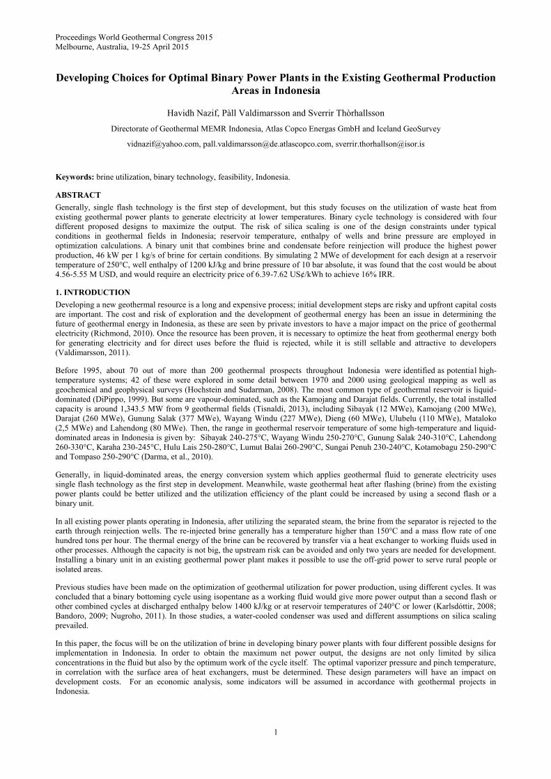
A flash cycle is the simplest and most conventional form for high-temperature geothermal power generation. Most geothermal
wells produce two phase fluids, consisting of brine and steam. The fluids also contain non-condensable gases and solid particles.
The water and solid particles are separated from the steam and gases using a separator. Thus, the steam fraction of the geothermal
fluid can be calculated based on the enthalpy and pressure. The process of an ideal separator is relatively simple since the outlets
are saturated steam and saturated brine. The saturated steam will go directly to the turbine which is coupled with a generator to
produce power.
Transferring heat from the exhaust steam into the cooling fluid causes the steam to condense. This creates a vacuum in the
condenser due to the collapse of steam and creates a driving force for the steam flow. The effect is higher output from the turbine.
As there is no need to recover the condensate for reuse in the process cycle, direct contact condensers are generally preferred since
they have lower initial capital cost and require less maintenance work. Figure 1 shows a simplified schematic diagram of a flash
cycle.
Figure 1: Schematic diagram of flash cycle
2.2 Binary cycle
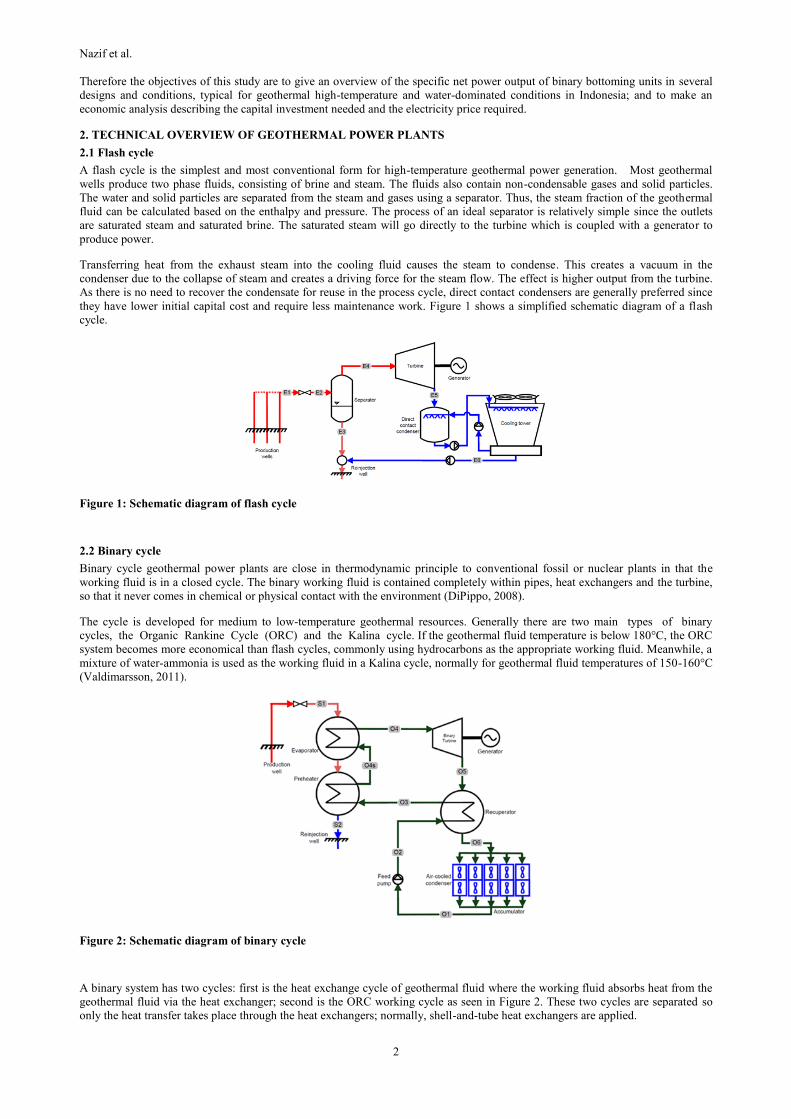
Binary cycle geothermal power plants are close in thermodynamic principle to conventional fossil or nuclear plants in that the
working fluid is in a closed cycle. The binary working fluid is contained completely within pipes, heat exchangers and the turbine,
so that it never comes in chemical or physical contact with the environment (DiPippo, 2008).
The cycle is developed for medium to low-temperature geothermal resources. Generally there are two main types of binary
cycles, the Organic Rankine Cycle (ORC) and the Kalina cycle. If the geothermal fluid temperature is below 180°C, the ORC
system becomes more economical than flash cycles, commonly using hydrocarbons as the appropriate working fluid. Meanwhile, a
mixture of water-ammonia is used as the working fluid in a Kalina cycle, normally for geothermal fluid temperatures of 150-160°C
(Valdimarsson, 2011).
Figure 2: Schematic diagram of binary cycle
A binary system has two cycles: first is the heat exchange cycle of geothermal fluid where the working fluid absorbs heat from the
geothermal fluid via the heat exchanger; second is the ORC working cycle as seen in Figure 2. These two cycles are separated so
only the heat transfer takes place through the heat exchangers; normally, shell-and-tube heat exchangers are applied.
Nazif et al.
3
The working fluid is selected both from the optimizing power output view and the critical temperature requirement. Table 1 shows
the critical temperature and pressure of some main working fluids applied in a binary cycle which must fit the geothermal fluid heat
source. The main components of a binary power plant are: heat exchangers (preheater, evaporator, condenser and recuperator), a
feed pump, a turbine, a generator and a cooling tower.
Table 1: Working fluid properties
Working
fluid
Critical
temperature (ºC)
Critical pressure
(bar abs)
Isopentane 187.2 33.70
Isobutane 134.7 36.40
n-pentane 196.5 33.64
n-butane 152 37.96
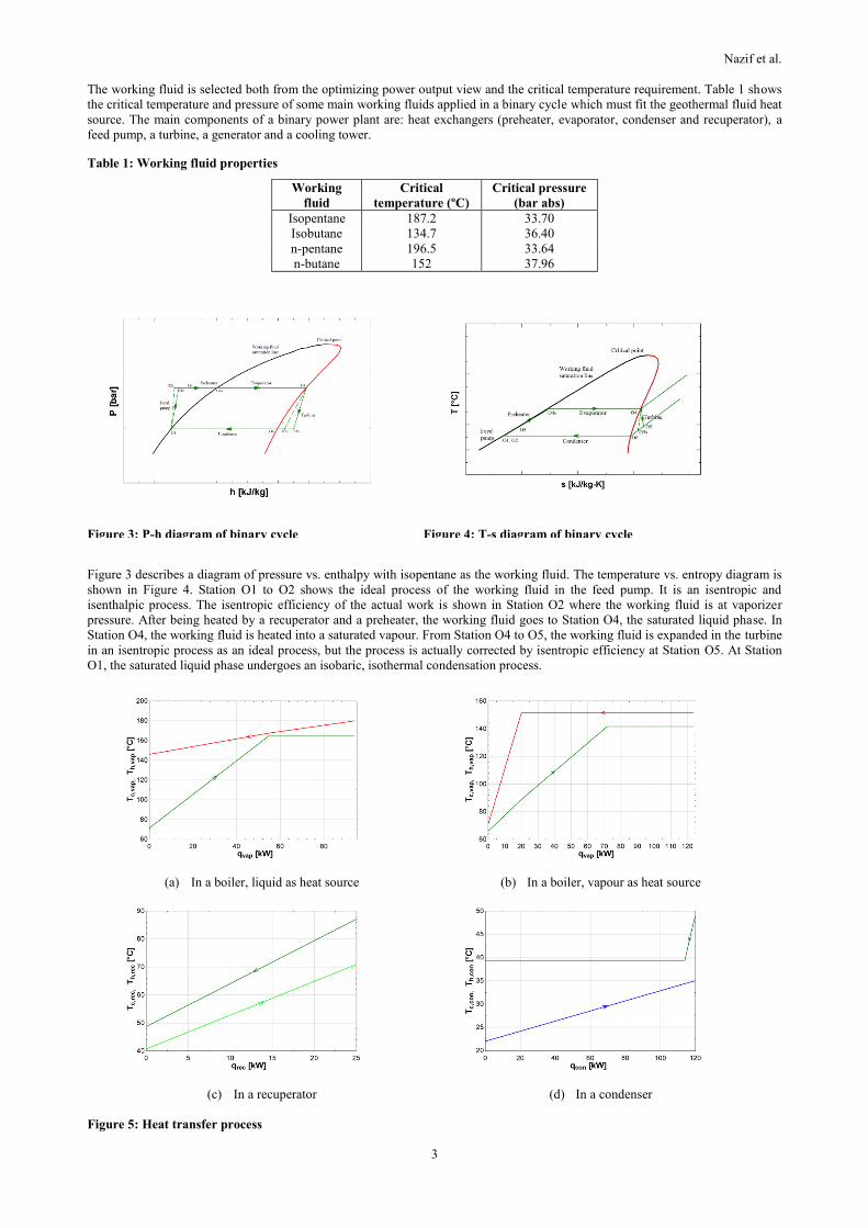
Figure 3: P-h diagram of binary cycle Figure 4: T-s diagram of binary cycle
Figure 3 describes a diagram of pressure vs. enthalpy with isopentane as the working fluid. The temperature vs. entropy diagram is
shown in Figure 4. Station O1 to O2 shows the ideal process of the working fluid in the feed pump. It is an isentropic and
isenthalpic process. The isentropic efficiency of the actual work is shown in Station O2 where the working fluid is at vaporizer
pressure. After being heated by a recuperator and a preheater, the working fluid goes to Station O4, the saturated liquid phase. In
Station O4, the working fluid is heated into a saturated vapour. From Station O4 to O5, the working fluid is expanded in the turbine
in an isentropic process as an ideal process, but the process is actually corrected by isentropic efficiency at Station O5. At Station
O1, the saturated liquid phase undergoes an isobaric, isothermal condensation process.
(a) In a boiler, liquid as heat source (b) In a boiler, vapour as heat source
(c) In a recuperator (d) In a condenser
Figure 5: Heat transfer process
Nazif et al.
4
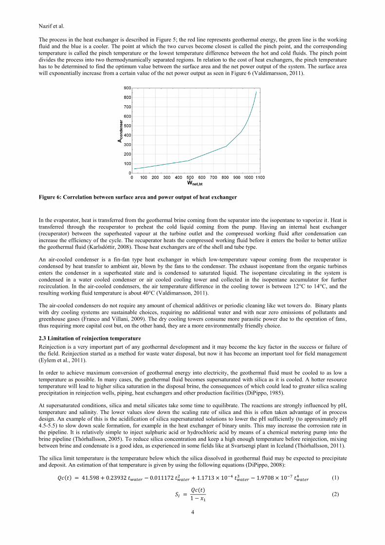
The process in the heat exchanger is described in Figure 5; the red line represents geothermal energy, the green line is the working
fluid and the blue is a cooler. The point at which the two curves become closest is called the pinch point, and the corresponding
temperature is called the pinch temperature or the lowest temperature difference between the hot and cold fluids. The pinch point
divides the process into two thermodynamically separated regions. In relation to the cost of heat exchangers, the pinch temperature
has to be determined to find the optimum value between the surface area and the net power output of the system. The surface area
will exponentially increase from a certain value of the net power output as seen in Figure 6 (Valdimarsson, 2011).
Figure 6: Correlation between surface area and power output of heat exchanger
In the evaporator, heat is transferred from the geothermal brine coming from the separator into the isopentane to vaporize it. Heat is
transferred through the recuperator to preheat the cold liquid coming from the pump. Having an internal heat exchanger
(recuperator) between the superheated vapour at the turbine outlet and the compressed working fluid after condensation can
increase the efficiency of the cycle. The recuperator heats the compressed working fluid before it enters the boiler to better utilize
the geothermal fluid (Karlsdóttir, 2008). Those heat exchangers are of the shell and tube type.
An air-cooled condenser is a fin-fan type heat exchanger in which low-temperature vapour coming from the recuperator is
condensed by heat transfer to ambient air, blown by the fans to the condenser. The exhaust isopentane from the organic turbines
enters the condenser in a superheated state and is condensed to saturated liquid. The isopentane circulating in the system is
condensed in a water cooled condenser or air cooled cooling tower and collected in the isopentane accumulator for further
recirculation. In the air-cooled condensers, the air temperature difference in the cooling tower is between 12°C to 14°C, and the
resulting working fluid temperature is about 40°C (Valdimarsson, 2011).
The air-cooled condensers do not require any amount of chemical additives or periodic cleaning like wet towers do. Binary plants
with dry cooling systems are sustainable choices, requiring no additional water and with near zero emissions of pollutants and
greenhouse gases (Franco and Villani, 2009). The dry cooling towers consume more parasitic power due to the operation of fans,
thus requiring more capital cost but, on the other hand, they are a more environmentally friendly choice.
2.3 Limitation of reinjection temperature
Reinjection is a very important part of any geothermal development and it may become the key factor in the success or failure of
the field. Reinjection started as a method for waste water disposal, but now it has become an important tool for field management
(Eylem et al., 2011).
In order to achieve maximum conversion of geothermal energy into electricity, the geothermal fluid must be cooled to as low a
temperature as possible. In many cases, the geothermal fluid becomes supersaturated with silica as it is cooled. A hotter resource
temperature will lead to higher silica saturation in the disposal brine, the consequences of which could lead to greater silica scaling
precipitation in reinjection wells, piping, heat exchangers and other production facilities (DiPippo, 1985).
At supersaturated conditions, silica and metal silicates take some time to equilibrate. The reactions are strongly influenced by pH,
temperature and salinity. The lower values slow down the scaling rate of silica and this is often taken advantage of in process
design. An example of this is the acidification of silica supersaturated solutions to lower the pH sufficiently (to approximately pH
4.5-5.5) to slow down scale formation, for example in the heat exchanger of binary units. This may increase the corrosion rate in
the pipeline. It is relatively simple to inject sulphuric acid or hydrochloric acid by means of a chemical metering pump into the
brine pipeline (Thórhallsson, 2005). To reduce silica concentration and keep a high enough temperature before reinjection, mixing
between brine and condensate is a good idea, as experienced in some fields like at Svartsengi plant in Iceland (Thórhallsson, 2011).
The silica limit temperature is the temperature below which the silica dissolved in geothermal fluid may be expected to precipitate
and deposit. An estimation of that temperature is given by using the following equations (DiPippo, 2008):
𝑄𝑐(𝑡) = 41.598 + 0.23932 𝑡𝑤𝑎𝑡𝑒𝑟 − 0.011172 𝑡𝑤𝑎𝑡𝑒𝑟2 + 1.1713 × 10⁻⁴ 𝑡𝑤𝑎𝑡𝑒𝑟
3 − 1.9708 × 10⁻⁷ 𝑡𝑤𝑎𝑡𝑒𝑟4 (1)
𝑆𝐼 =
𝑄𝑐(𝑡)
1 − 𝑥1 (2)
Nazif et al.
5
𝑆𝐼𝐼 =
𝑆𝐼
1 − 𝑥2 (3)
𝑙𝑜𝑔10 𝑠𝑎𝑚𝑜𝑟𝑝ℎ𝑜𝑢𝑠 = −6.116 + 0.01625 𝑇𝑤𝑎𝑡𝑒𝑟 − 1.758 × 10⁻⁵ 𝑇𝑤𝑎𝑡𝑒𝑟2 + 5.257 × 10⁻⁹ 𝑇𝑤𝑎𝑡𝑒𝑟
3 (4)
where 𝑄𝑐(𝑡), 𝑡𝑤𝑎𝑡𝑒𝑟, 𝑆𝐼, 𝑆𝐼𝐼, 𝑥1, 𝑥2, 𝑇𝑤𝑎𝑡𝑒𝑟 are quartz solubility in reservoir [ppm], reservoir temperature [°C], concentration of
silica in the brine after first flashing [ppm], concentration of silica in the brine after second flashing [ppm], steam quality from first
flashing, steam quality from second flashing, equilibrium solubility of amorphous silica for zero salinity [ppm] (must be multiplied
by 58,000 to obtain ppm), and absolute temperature of discharge brine [K] respectively.
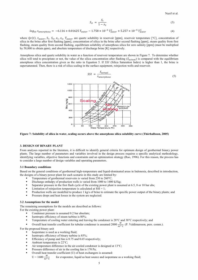
Amorphous silica and quartz solubility in water as a function of reservoir temperature are shown in Figure 7. To determine whether
silica will tend to precipitate or not, the value of the silica concentration after flashing (𝑆𝑎𝑐𝑡𝑢𝑎𝑙) is compared with the equilibrium
amorphous silica concentration given as the ratio in Equation 5. If 𝑆𝑆𝐼 (Silica Saturation Index) is higher than 1, the brine is
supersaturated. Then, there is a risk of silica scaling in the surface equipment, reinjection wells and reservoir.
𝑆𝑆𝐼 =
𝑆𝑎𝑐𝑡𝑢𝑎𝑙
𝑠𝑎𝑚𝑜𝑟𝑝ℎ𝑜𝑢𝑠
(5)
Figure 7: Solubility of silica in water, scaling occurs above the amorphous silica solubility curve (Thórhallsson, 2005)
3. DESIGN OF BINARY PLANT
From analyses reported in the literature, it is difficult to identify general criteria for optimum design of geothermal binary power
plants. The large number of parameters and variables involved in the design process requires a specific analytical methodology,
identifying variables, objective functions and constraints and an optimization strategy (Rao, 1996). For this reason, the process has
to consider a large number of design variables and operating parameters.
3.1 Boundary conditions
Based on the general conditions of geothermal high-temperature and liquid-dominated areas in Indonesia, described in introduction,
the designs of a binary power plant for each scenario in this study are limited by:
Temperature of geothermal reservoirs is varied from 230 to 260°C;
Discharge enthalpy of production wells is varied from 1000 to 1400 kJ/kg;
Separator pressure in the first flash cycle of the existing power plant is assumed at 6.5, 8 or 10 bar abs;
Limitation of reinjection temperature is calculated at SSI = 1;
Production wells are modelled to produce 1 kg/s of brine to estimate the specific power output of the binary plants; and
Pressure drops and heat losses in the system are neglected.
3.2 Assumptions for the model
The remaining assumptions for the models are described as follows:
For the existing power plant:
Condenser pressure is assumed 0.2 bar absolute;
Isentropic efficiency of steam turbine is 80%;
Temperature of cooling water entering and leaving the condenser is 28°C and 38°C respectively; and
Overall heat transfer coefficient for tubular condenser is assumed 2000 𝑊
𝑚2 °𝐶 (P. Valdimarsson, pers. comm.).
For the proposed binary unit
Isopentane is used as a working fluid;
Isentropic efficiency of binary turbine is 85%;
Efficiency of pump and fan is 0.75 and 0.65 respectively;
Ambient temperature is 22°C;
Air temperature difference in the air-cooled condenser is designed at 13°C;
Pressure difference of air in the cooling fan is 170 Pa;
Overall heat transfer coefficient (U) of heat exchangers is assumed:
U = 1600 𝑊
𝑚2 °𝐶 for evaporator, liquid as heat source and isopentane as a working fluid;

Nazif et al.
6
U = 1800 𝑊
𝑚2 °𝐶 for evaporator, vapour as heat source and isopentane as a working fluid;
U = 1200 𝑊
𝑚2 °𝐶 for preheater, liquid as heat source and isopentane as a working fluid;
U = 300 𝑊
𝑚2 °𝐶 for recuperator, isopentane-isopentane; and
U = 500 𝑊
𝑚2 °𝐶 for air-cooled condenser and isopentane as a working fluid.
3.3 Proposed scenarios
Several proposed scenarios of a binary bottoming unit, with regard to preventing silica scaling, were designed as follows:
Scenario 1
As shown in Figure 8, the binary bottoming cycle was designed without any changes in the existing power plant; brine from the
existing separator directly heats the secondary working fluid in the boiler. The condensate from the direct-contact condenser in the
existing power plant is not expected to mix with the brine because it is not pure water; it consists of oxygen, sulphur etc., usually
used for shallow reinjection (Thórhallsson, 2011). The minimum temperature of the brine leaving the preheater was calculated
according to SSI = 1 at Station S2, SSIS2 = 1. This is to say that the fluid will be exactly at saturation with respect to silica and
scaling is not expected.
Figure 8: Schematic diagram of Scenario 1, brine used
directly as heat source
Figure 9: Schematic diagram of Scenario 2, steam as a heat
source after flashing the brine
Scenario 2
As shown in Figure 9, the binary bottoming cycle was designed without any changes in the existing power plant; brine from the
existing separator goes to a second separator and then steam heats the secondary working fluid in the boiler; this can be called a
flashing binary cycle. The minimum temperature of the brine leaving the preheater depends on SSI = 1, measured at the mixing
point of the brine from the low pressure separator and the preheater or from Stations S4 and S3, SSIS3+S4 = 1.
Scenario 3
As shown in Figure 10, the binary bottoming cycle was designed by replacing the direct contact condenser with a tubular condenser
in the existing power plant in order to get condensate at zero ppm of any minerals or pure water. The minimum temperature of the
brine leaving the preheater was calculated according to SSI = 1 of the reinjection water, after mixing between the brine leaving the
preheater (Station S2) and the condensate from the existing power plant (Station E7), SSIS2+E7 = 1.
Scenario 4
As shown in Figure 11, the brine from the high pressure separator is flashed into low pressure separator, and the steam so obtained
is used to heat the secondary working fluid in the boiler. The direct contact condenser is replaced with a tubular condenser in the
existing power plant in order to get condensate at zero ppm of any minerals or pure water. The minimum temperature of the brine
leaving the preheater depends on SSI = 1 of the reinjection water, after mixing between the condensate from existing power plant
(Station E7), the brine from the low pressure separator (Station S4) and the brine from the preheater (Station S3), SSIS3+S4+E7 = 1.
Nazif et al.
7
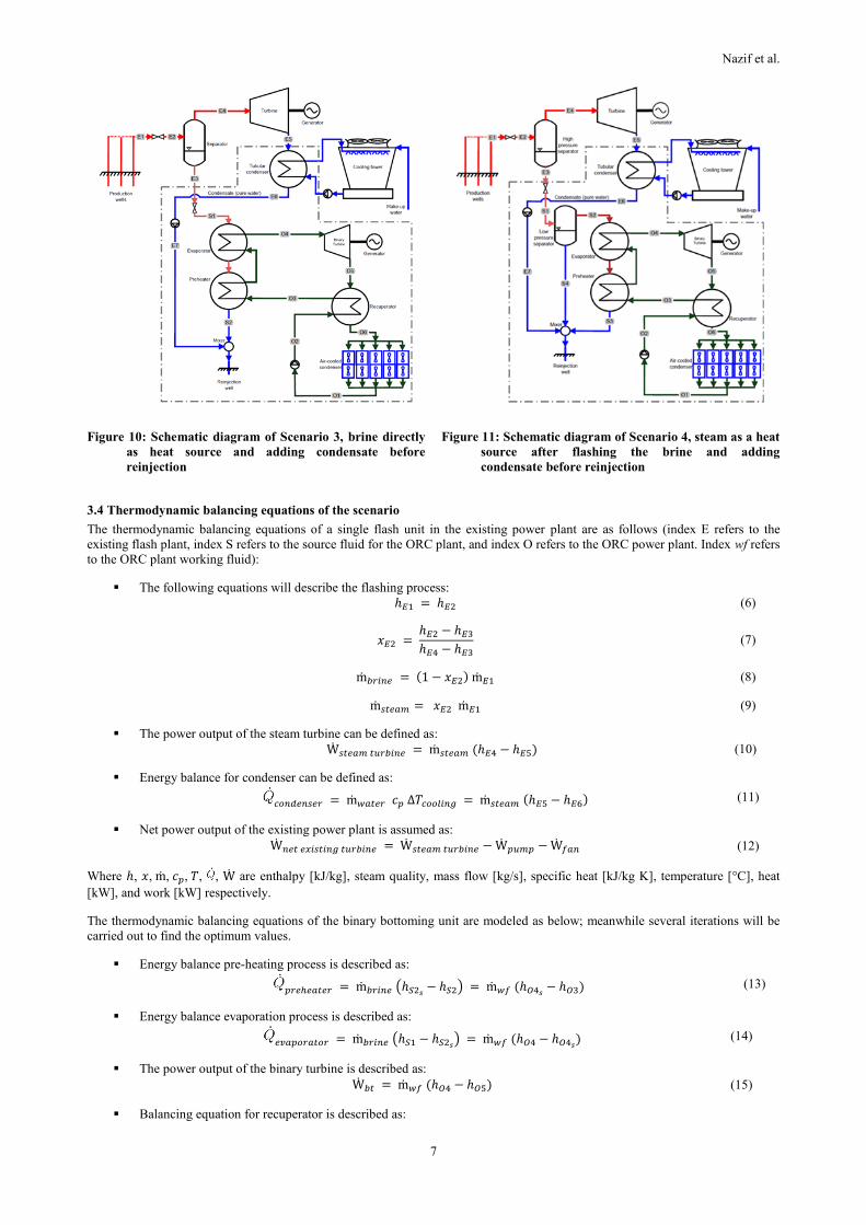
Figure 10: Schematic diagram of Scenario 3, brine directly
as heat source and adding condensate before
reinjection
Figure 11: Schematic diagram of Scenario 4, steam as a heat
source after flashing the brine and adding
condensate before reinjection
3.4 Thermodynamic balancing equations of the scenario
The thermodynamic balancing equations of a single flash unit in the existing power plant are as follows (index E refers to the
existing flash plant, index S refers to the source fluid for the ORC plant, and index O refers to the ORC power plant. Index wf refers
to the ORC plant working fluid):
The following equations will describe the flashing process:
ℎ𝐸1 = ℎ𝐸2 (6)
𝑥𝐸2 =
ℎ𝐸2 − ℎ𝐸3
ℎ𝐸4 − ℎ𝐸3 (7)
ṁ𝑏𝑟𝑖𝑛𝑒 = (1 − 𝑥𝐸2) ṁ𝐸1 (8)
ṁ𝑠𝑡𝑒𝑎𝑚 = 𝑥𝐸2 ṁ𝐸1 (9)
The power output of the steam turbine can be defined as:
Ẇ𝑠𝑡𝑒𝑎𝑚 𝑡𝑢𝑟𝑏𝑖𝑛𝑒 = ṁ𝑠𝑡𝑒𝑎𝑚 (ℎ𝐸4 − ℎ𝐸5) (10)
Energy balance for condenser can be defined as:
𝑐𝑜𝑛𝑑𝑒𝑛𝑠𝑒𝑟 = ṁ𝑤𝑎𝑡𝑒𝑟 𝑐𝑝 ∆𝑇𝑐𝑜𝑜𝑙𝑖𝑛𝑔 = ṁ𝑠𝑡𝑒𝑎𝑚 (ℎ𝐸5 − ℎ𝐸6) (11)
Net power output of the existing power plant is assumed as:
Ẇ𝑛𝑒𝑡 𝑒𝑥𝑖𝑠𝑡𝑖𝑛𝑔 𝑡𝑢𝑟𝑏𝑖𝑛𝑒 = Ẇ𝑠𝑡𝑒𝑎𝑚 𝑡𝑢𝑟𝑏𝑖𝑛𝑒 − Ẇ𝑝𝑢𝑚𝑝 − Ẇ𝑓𝑎𝑛 (12)
Where ℎ, 𝑥, ṁ, 𝑐𝑝, 𝑇, , Ẇ are enthalpy [kJ/kg], steam quality, mass flow [kg/s], specific heat [kJ/kg K], temperature [°C], heat
[kW], and work [kW] respectively.
The thermodynamic balancing equations of the binary bottoming unit are modeled as below; meanwhile several iterations will be
carried out to find the optimum values.
Energy balance pre-heating process is described as:
𝑝𝑟𝑒ℎ𝑒𝑎𝑡𝑒𝑟 = ṁ𝑏𝑟𝑖𝑛𝑒 (ℎ𝑆2𝑠
− ℎ𝑆2) = ṁ𝑤𝑓 (ℎ𝑂4𝑠− ℎ𝑂3) (13)
Energy balance evaporation process is described as:
𝑒𝑣𝑎𝑝𝑜𝑟𝑎𝑡𝑜𝑟 = ṁ𝑏𝑟𝑖𝑛𝑒 (ℎ𝑆1 − ℎ𝑆2𝑠
) = ṁ𝑤𝑓 (ℎ𝑂4 − ℎ𝑂4𝑠) (14)
The power output of the binary turbine is described as:
Ẇ𝑏𝑡 = ṁ𝑤𝑓 (ℎ𝑂4 − ℎ𝑂5) (15)
Balancing equation for recuperator is described as:
Nazif et al.
8
𝑟𝑒𝑐𝑢𝑝𝑒𝑟𝑎𝑡𝑜𝑟 = ṁ𝑤𝑓 (ℎ𝑂5 − ℎ06) = ṁ𝑤𝑓 (ℎ𝑂3 − ℎ2) (16)
Energy balance for condenser is described as:
𝑐𝑜𝑛𝑑𝑒𝑛𝑠𝑒𝑟 = ṁ𝑎𝑖𝑟 𝑐𝑝 ∆𝑇𝑐𝑜𝑜𝑙𝑖𝑛𝑔 = ṁ𝑤𝑓 (ℎ𝑂6 − ℎ𝑂1) (17)
Heat exchangers area can be calculated as:
= 𝑈𝐴 × 𝐿𝑀𝑇𝐷 (18)
𝐿𝑀𝑇𝐷 =
(𝑇ℎ𝑜𝑡,𝑖𝑛 − 𝑇𝑐𝑜𝑙𝑑,𝑜𝑢𝑡) − (𝑇ℎ𝑜𝑡,𝑜𝑢𝑡 − 𝑇𝑐𝑜𝑙𝑑,𝑖𝑛)
ln [𝑇ℎ𝑜𝑡,𝑖𝑛 − 𝑇𝑐𝑜𝑙𝑑,𝑜𝑢𝑡
𝑇ℎ𝑜𝑡,𝑜𝑢𝑡 − 𝑇𝑐𝑜𝑙𝑑,𝑖𝑛]
(19)
where U, A, LMTD are overall heat transfer coefficient [°C/m2], heat transferring area [m2]; and Logarithmic
Mean Temperature Difference [°C] respectively.
The following equations are used to calculate the power of pump and fan:
Ẇ𝑝𝑢𝑚𝑝 = 𝑣𝑤𝑓 ∆p
𝜂𝑝𝑢𝑚𝑝; Ẇ𝑓𝑎𝑛 =
𝑣𝑎𝑖𝑟 ∆p
𝜂𝑓𝑎𝑛 (20)
𝑣𝑤𝑓 = ṁ𝑤𝑓
𝜌𝑤𝑓; 𝑣𝑎𝑖𝑟 =
ṁ𝑎𝑖𝑟
𝜌𝑎𝑖𝑟; (21)
Net power output of binary power cycle is calculated as:
Ẇ𝑛𝑒𝑡 𝑏𝑖𝑛𝑎𝑟𝑦 = Ẇ𝑡𝑢𝑟𝑏𝑖𝑛𝑒 − Ẇ𝑓𝑒𝑒𝑑𝑝𝑢𝑚𝑝 − Ẇ𝑓𝑎𝑛 (22)
The thermodynamic balancing equations of waste re-injected fluid are given as:
ṁ𝑟𝑒𝑖𝑛𝑗𝑒𝑐𝑡𝑖𝑜𝑛 ℎ𝑟𝑒𝑖𝑛𝑗𝑒𝑐𝑡𝑖𝑜𝑛 = ṁ𝑏𝑟𝑖𝑛𝑒 ℎ𝑆2 + ṁ𝑐𝑜𝑛𝑑𝑒𝑛𝑠𝑎𝑡𝑒 ℎ𝐸7 (24)
ṁ𝑟𝑒𝑖𝑛𝑗𝑒𝑐𝑡𝑖𝑜𝑛 𝑆𝑎𝑐𝑡𝑢𝑎𝑙,𝑟𝑒𝑖𝑛𝑗𝑒𝑐𝑡𝑖𝑜𝑛 = ṁ𝑏𝑟𝑖𝑛𝑒 𝑆𝑎𝑐𝑡𝑢𝑎𝑙,𝑆2 + ṁ𝑐𝑜𝑛𝑑𝑒𝑛𝑠𝑎𝑡𝑒 𝑆𝑎𝑐𝑡𝑢𝑎𝑙,𝑐𝑜𝑛𝑑𝑒𝑛𝑠𝑎𝑡𝑒 (25)
𝑆𝑆𝐼𝑟𝑒𝑖𝑛𝑗𝑒𝑐𝑡𝑖𝑜𝑛 =
𝑆𝑎𝑐𝑡𝑢𝑎𝑙,𝑟𝑒𝑖𝑛𝑗𝑒𝑐𝑡𝑖𝑜𝑛
𝑆𝑎𝑚𝑜𝑟𝑝ℎ𝑜𝑢𝑠 𝑠𝑖𝑙𝑖𝑐𝑎 𝑠𝑜𝑙𝑢𝑏𝑖𝑙𝑖𝑡𝑦 𝑎𝑡 𝑟𝑒𝑖𝑛𝑗𝑒𝑐𝑡𝑖𝑜𝑛 𝑡𝑒𝑚𝑝𝑒𝑟𝑎𝑡𝑢𝑟𝑒 (26)
4. ECONOMIC OVERVIEW OF BINARY POWER PLANT
4.1 Review of the purchased equipment cost
Estimating the cost of purchased equipment including spare parts and components is the first step in any detailed cost estimation.
To find references from the exact cost of the previous project is a difficult thing due to confidentiality and fluctuation of market
prices. Hence, in this report will be reviewed some published papers and information summarized in Table 2. On the other hand, the
most reliable way to estimate cost is to obtain quotations from vendors.
Table 2: Review of purchased equipment cost Table 3: Assumed thumb values for equipment costs
4.2 Cost estimation for the model
The base costs of main equipment are estimated based on the review stated in Section 4.1 and the experts experiences as seen in
Table experience of experts as seen in Table 3. In this study, the costs are assumed thumb values although best estimates should be
obtained through vendor quotations. Equation 27 was used to cost of purchased equipment. The parameter of equipment size can
be surface area, power or capacity. In this case, the remaining development costs were assumed to be a percentage of the total
Purchased Equipment Cost (PEC). The total investment cost to develop a binary bottoming unit will be calculated for all proposed
scenarios at turbine capacity of 2 MWe in order to estimate the possible electricity price required for each design. All costs related
to the upstream activities are not included.
4.3 Methodology and process of electricity price determination
In this study, a financial analysis was implemented with reference to common geothermal investment parameters and regulations in
Indonesia. Therefore, the first step of the assessment was to estimate capital investment and then figure out the annual cost, annual
revenue, annual cash flow, as well as Net Present Value (NPV) for each scenario. The annual cost includes operation and
maintenance costs (O&M) and brine compensation. In order to be a feasible project, the required Internal Rate of Return (IRR) is
fixed by varying the electricity price.

Nazif et al.
9
Danar (2010) described the fiscal and economic assumptions used for geothermal project proposals in Indonesia as follows: income
tax 32.5%; investment allowance 5% per year for the first 6 years; accelerated depreciation: 8 years, 25% (declining balance
method); no tax for imported goods; capacity factor 90%; lifespan of power plant 30 years; and IRR: 16%. Other assumed
parameters include: O&M cost: 0.5 USC/kWhel with 1.5% escalation per year; electricity price escalation: 2.5% per year for 25%
of base price; brine compensation: 0.25 USC/kWhel; and no CDM/carbon revenue.
5. RESULTS AND DISCUSSION
Detailed calculations and optimization of the geothermal fluid from production wells to the reinjection process passing through a
binary bottoming unit of four different proposed designs were programmed with Engineering Equation Solver (EES) software as a
part of this study. The net power output was maximized by varying: vaporizer pressure; condenser pressure; pinch temperature of
the condenser, recuperator, as well as boiler; and brine flashing pressure.
5.1 The calculation results for Scenario 1
For the first scenario of the binary bottoming cycle, the net power output per 1 kg/s of brine from the high pressure separator with a
pressure of 6.5, 8 and 10 bar as a function of the enthalpy of wells for different reservoir temperatures can be seen in Table 4. The
vaporizer pressure of the binary unit ranged from 15.26 to 27.98 bar. No output was obtained when operated at a reservoir
temperature of 250°C with a well enthalpy of 1400 kJ/kg or at a reservoir temperature of 260°C with several different well
enthalpies.
Table 4: Calculation results for Scenario 1 Table 5: Calculation results for Scenario 2
5.2 The calculation results for Scenario 2
For the second scenario of the binary bottoming cycle, the net power output per 1 kg/s of brine from the main separator with a
pressure of 6.5, 8 and 10 bar as a function of the enthalpy of wells for different reservoir temperatures can be seen in Table 5. The
vaporizer pressure of the binary unit ranged from 10.21 to 23.8 bar with the second separator pressure ranging from 2.46 to 8.89
bar. No output was obtained for the same brine conditions as in Scenario 1.
5.3 The calculation results for Scenario 3
For the third scenario of the binary bottoming cycle, the net power output per 1 kg/s of brine from the main separator with a
pressure of 6.5, 8 and 10 bar as a function of the enthalpy of wells for different reservoir temperatures can be seen in Table 6. The
vaporizer pressure of the binary unit ranged from 14.77 to 27.56 bar. No output was obtained for the same brine conditions as in
Scenario 1.
5.4 The calculation results for Scenario 4
For the fourth scenario of the binary bottoming cycle, the net power output per 1 kg/s of brine from the main separator with a
pressure of 6.5, 8 and 10 bar as a function of the enthalpy of wells for different reservoir temperatures can be seen in Table 7. The
vaporizer pressure of the binary unit ranged from 9.83 to 23.83 bar with a second separator pressure ranging from 2.32 to 8.36 bar.
No output was obtained for the same brine conditions as in Scenario 1.
5.5 Comparison of Scenarios
The binary bottoming unit of Scenario 3 gave the highest power production. The lowest specific net power output was found in
Scenario 2. In some conditions, Scenario 4 had a higher net power output than Scenario 1 but was otherwise lower, as follows:
At brine pressure of 6.5 bar, Scenario 4 had a higher power production output than Scenario 1 for a reservoir temperature of
250-260°C, for a reservoir temperature of 240°C with well enthalpy of 1200-1400 kJ/kg and for a reservoir temperature of
230°C with a well enthalpy of 1300-1400 kJ/kg;
At a brine pressure of 8 bar, Scenario 4 had a higher power production output than Scenario 1 for a reservoir temperature of
260°C, for a reservoir temperature of 250°C with a well enthalpy of 1200-1400 kJ/kg, for a reservoir temperature of 240°C
with a well enthalpy of 1300-1400 kJ/kg and for a reservoir temperature of 230°C with a well enthalpy of 1400 kJ/kg; and
At a brine pressure of 10 bar, Scenario 4 had higher power production output than Scenario 1 for the reservoir temperature of
250-260°C with a well enthalpy of 1300-1400 kJ/kg and for a reservoir temperature of 240°C with a well enthalpy of 1400
kJ/kg.
Nazif et al.
10
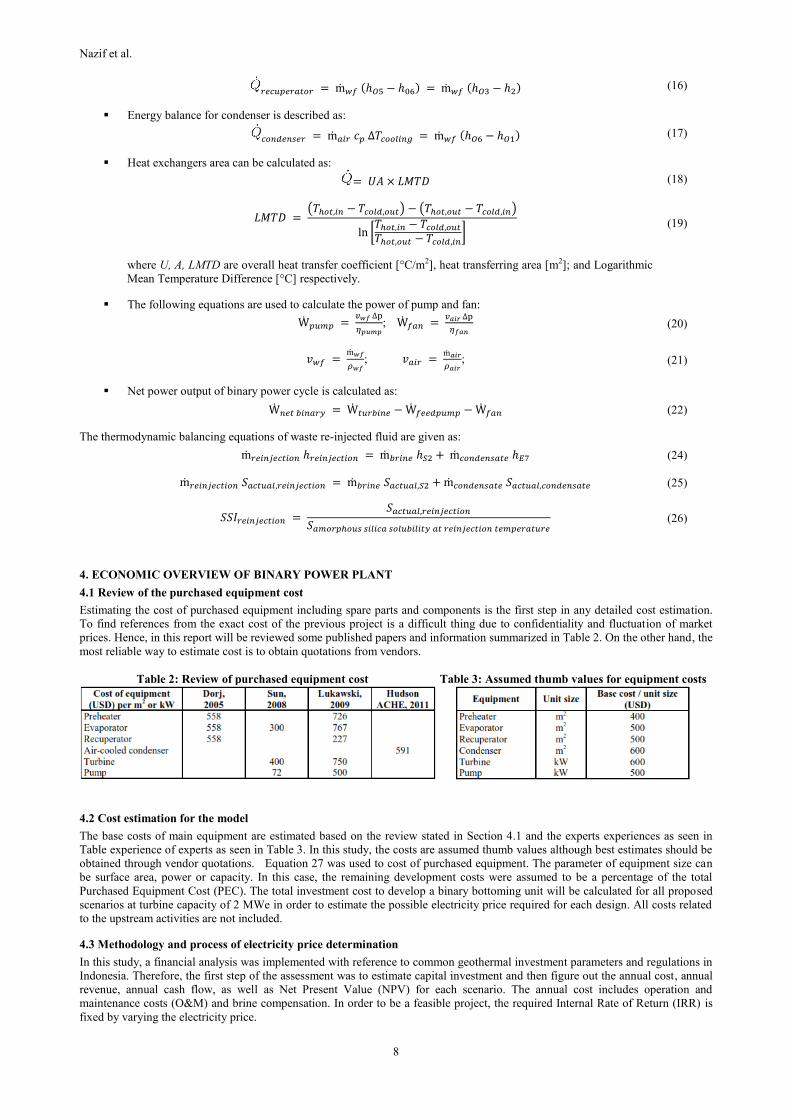
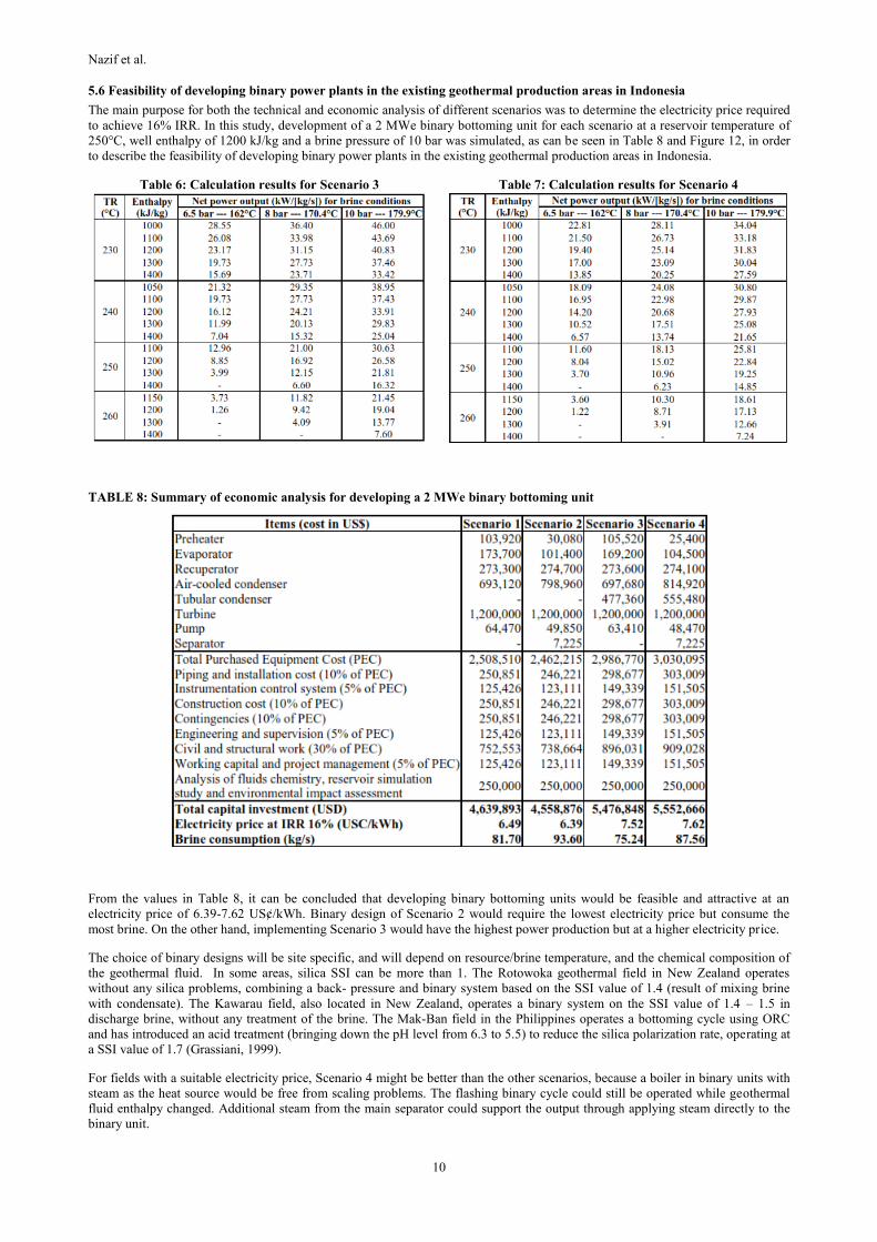
5.6 Feasibility of developing binary power plants in the existing geothermal production areas in Indonesia
The main purpose for both the technical and economic analysis of different scenarios was to determine the electricity price required
to achieve 16% IRR. In this study, development of a 2 MWe binary bottoming unit for each scenario at a reservoir temperature of
250°C, well enthalpy of 1200 kJ/kg and a brine pressure of 10 bar was simulated, as can be seen in Table 8 and Figure 12, in order
to describe the feasibility of developing binary power plants in the existing geothermal production areas in Indonesia.
Table 6: Calculation results for Scenario 3 Table 7: Calculation results for Scenario 4
TABLE 8: Summary of economic analysis for developing a 2 MWe binary bottoming unit
From the values in Table 8, it can be concluded that developing binary bottoming units would be feasible and attractive at an
electricity price of 6.39-7.62 US¢/kWh. Binary design of Scenario 2 would require the lowest electricity price but consume the
most brine. On the other hand, implementing Scenario 3 would have the highest power production but at a higher electricity price.
The choice of binary designs will be site specific, and will depend on resource/brine temperature, and the chemical composition of
the geothermal fluid. In some areas, silica SSI can be more than 1. The Rotowoka geothermal field in New Zealand operates
without any silica problems, combining a back- pressure and binary system based on the SSI value of 1.4 (result of mixing brine
with condensate). The Kawarau field, also located in New Zealand, operates a binary system on the SSI value of 1.4 – 1.5 in
discharge brine, without any treatment of the brine. The Mak-Ban field in the Philippines operates a bottoming cycle using ORC
and has introduced an acid treatment (bringing down the pH level from 6.3 to 5.5) to reduce the silica polarization rate, operating at
a SSI value of 1.7 (Grassiani, 1999).
For fields with a suitable electricity price, Scenario 4 might be better than the other scenarios, because a boiler in binary units with
steam as the heat source would be free from scaling problems. The flashing binary cycle could still be operated while geothermal
fluid enthalpy changed. Additional steam from the main separator could support the output through applying steam directly to the
binary unit.

Nazif et al.
11
Figure 12: Economic feasibility of 2 MWe binary unit
6. CONCLUSIONS AND RECOMMENDATIONS
The proposed designs in this study were devised such that despite the extraction of more heat from the brine, there would be no
scaling in the reinjection wells. This depends on how much the brine can be cooled, but by adding condensate from the tubular
condenser to the brine, a disposal temperature of 127.4-128.6°C would be possible for brine of original reinjection temperatures
of 142.8-163.5°C (for different enthalpies at reservoir temperature of 250°C and brine pressure of 10 bar).
Developing binary units in the existing geothermal production areas gives a varied range of net power outputs based on different
design scenarios and reservoir temperature as well as brine conditions. After comparing four different proposed designs, it was
found that implementing the binary design of Scenario 3 would produce the highest power, 46 kW per 1 kg/s of brine (at a reservoir
temperature of 230°C, well enthalpy of 1000 kJ/kg and brine pressure of 10 bar); Scenario 2 gave the lowest power.
Power production increases gradually by decreasing the reinjection temperature. In order to obtain the maximum power output, the
bottoming units must be designed at the minimum reinjection temperature level that is free from scaling possibilities, both in power
plant components and the reinjection well itself.
From simulating 2 MWe of development for each proposed scenario at a reservoir temperature of 250°C, well enthalpy of 1200
kJ/kg and a brine pressure of 10 bar, as well as according to common geothermal projects financing in Indonesia, it would cost
about 4.56-5.55 M USD and would require an electricity price of 6.39-7.62 US₵/kWh to achieve 16% IRR. Scenario 2 offers the
lowest electricity price but consumes the most brine. On the other hand, implementing Scenario 3 would give the highest output of
power production but would also require a higher electricity price.
In areas where there is no restriction on the availability of water for the cooling tower, constructing binary bottoming units
with a wet-cooled condenser would result in a lower electricity price and make the projects more feasible and attractive.
REFERENCES
Bandoro Swandaru, R., 2009: Modelling and optimization of possible bottoming units for general single flash geothermal power
plants. University of Iceland, MSc thesis, UNU-GTP, Iceland, report 2, 29 pp.
Cédric, N.H., 2005: Factors affecting costs of geothermal power development. Geothermal Energy Association, Washington, DC,
49 pp.
Danar, A., 2010: Determining geothermal electricity prices based on investment decisions (in Indonesian). Papers presented at
Short Course 5 before World Geothermal Congress 2010, Jakarta, Indonesia, 13 pp.
Darma, S., Poernomo, A., Pramono, A., Brahmantio, E.A., Kamah, Y., and Suhermanto, G., 2010: The role of Pertamina
Geothermal Energy (PGE) in completing geothermal power plants achieving 10,000 MW in Indonesia. Proceedings of the
World Geothermal Congress 2010, Bali, Indonesia, 7 pp.
DiPippo, R., 1985: A simplified method for estimating the silica scaling potential in geothermal power plants. Geothermal
Resources Council, Bulletin, May, 3-9.
DiPippo, R., 1999: Small geothermal power plants: Design, performance and economics. GHC Bulletin, June, 8 pp.
DiPippo, R., 2008: Geothermal power plants. Principles, applications, case studies and environmental impact. Elsevier
Ltd., Kidlington, UK, 493 pp.
Franco, A., and Villani, M., 2009: Optimal design of binary cycle power plants for water-dominated, medium temperature
geothermal fields. Geothermics, 38, 379-391.
Grassiani, M., 1999: Siliceous scaling aspects of geothermal power generation using binary cycle heat recovery. Bulletin
d’Hydrogèologie, 17, 385-392.

Nazif et al.
12
Tisnaldi, 2013: Geothermal development in Indonesia.
Hochstein, M.P., and Sudarman, S., 2008: History of geothermal exploration in Indonesia from 1970 to 2000. Geothermics, 37,
220-266.
Hudson ACHE, 2011: Hudson Products Corporation online software provides a method for estimating of air-cooled heat
exchangers (ACHE) size, weight, price, and power consumption in the planning stage. Hudson Products Corporation.
Webpage: www.hudsonproducts.com/products/finfan/software.html.
Karlsdóttir, M.R., 2008: Utilization of geothermal brine for electrical power production. University of Iceland, Reykjavík, MSc
thesis, 92 pp.
Nugroho, A.J., 2011: Optimization of electrical power production from high-temperature geothermal fields with respect to silica
scaling problems. University of Iceland, MSc thesis, UNU-GTP, Iceland, report 2, 49 pp.
Richmond, 2010: An assessment of geothermal resource risks in Indonesia. GeothermEx, Inc., California, USA, 129 pp.
Thórhallsson, S., 2005: Common problems faced in geothermal generation and how to deal with them. Paper presented at
Workshop for Decision Makers on Geothermal Projects and Management, organized by UNU-GTP and KenGen in Naivasha,
Kenya, 12 pp.
Thórhallsson, S., 2011: Problems of geothermal utilization. UNU-GTP, Iceland, unpublished lecture notes.
Valdimarsson, P., 2011: High-temperature geothermal energy utilization. UNU-GTP, Iceland, unpublished lecture notes.