Embed Size (px)
Citation preview
Application Note
Developing Call Monitoring Applications Using Dialogic® SS7 Signaling and Media Products

Application Note Developing Call Monitoring Applications Using Dialogic® SS7 Signaling and Media Products
Executive Summary
This application note provides information about developing a call monitoring application using the Dialogic® SS7 signaling and media products. Dialogic developed a sample application that provides both a starting point and a reference for those who choose to develop an SS7-based application that monitors SS7 links and records calls on the links. Call recording can be triggered based on information related to the call. Calls may be recorded to multiple files or streamed through the data net-work for real-time monitoring.
The reference application and supporting applications’ source codes are available for download with this application note.
Developing Call Monitoring Applications Using Dialogic® SS7 Signaling and Media Products Application Note
1
Table of ContentsIntroduction ........................................................................................................... 2
Architecture ........................................................................................................... 2
Simulating a Signaling Environment ................................................................ 3
Stimulus Server .............................................................................................. 4
Streaming Server ............................................................................................ 4
Monitor Server ................................................................................................ 4
Integrating SS7 Components with Media Components ............................................ 4
system.txt ....................................................................................................... 5
config.txt ......................................................................................................... 5
gcss7.cfg ........................................................................................................ 5
Mapping SS7 Channel Identification Codes to Network Devices....................... 5
Walkthrough of the Sample Reference Application ................................................. 6
Overivew ......................................................................................................... 6
Stimulus Server .............................................................................................. 6
Streaming Server ............................................................................................ 6
Monitor Server ................................................................................................ 6
SignalingMonitor Application Description ................................................................ 6
Functionality by Class ..................................................................................... 6
Dialogic® Signaling API Usage ..................................................................... 11
Dialogic® Media API Usage .......................................................................... 11
Appendix A. Signaling Configuration ..................................................................... 12
Appendix B. Media Configuration ......................................................................... 16
Acronyms ............................................................................................................ 18
For More Information ........................................................................................... 18
Materials List for Reference Application ......................................................... 19
Introduction
Signaling System 7 (SS7) is a collection of
telecommunications standard protocols used to provide
communications between various Public Switched
Telephone Network (PSTN) network elements. An
example of SS7 control messages are the signaling
messages exchanged to set up a telephone call.
Monitoring signaling messages used to control a call can
provide information such as the “called” and “calling”
party numbers, as well as details of a call’s duration.
Using this type of information, it is possible to develop a
“Lawful Intercept” type application, where the signaling
messages of a call are monitored and the audio (speech)
path is recorded for the call’s duration.
This document provides information that can be used
by those who choose to build a monitoring application
using Dialogic® signaling and media products. The
accompanying reference application is an example of
how the Dialogic® signaling and media product APIs
can be used to implement a monitoring application.
The architectures of both the development and
the production environments are presented, as is a
walkthrough of the accompanying monitoring software.
A Zip file containing the reference application (the
monitoring application) and the supporting software
source code (for the stimulus application and the
streaming application) are available for download (see the
For More Information section).
Architecture
The PSTN is comprised of multiple network elements that perform functions such as communicating with each other in order to traverse a call from a calling party to a called party, and checking on the validity of a subscriber. Some of these network elements can be Class 5 central office switches, Class 4 tandem switches, or databases containing subscriber information and servers that provide additional call control, among others. Each of these network elements use SS7 messages to communicate with each other. Additionally, Signal Transfer Points (STPs) act as routers for SS7 messages to allow this communication. Bearer paths, made up of T1/E1 spans, DS3 spans, or optical links, provide the conduits for the voice traffic. These network elements use SS7 messaging to facilitate call delivery over the PSTN, so that the voice traffic can be effectively routed through the PSTN. When a call is made in the PSTN network, SS7 messages are generated and routed through the network from the local switch the caller is using to the switch to which the called party is connected.
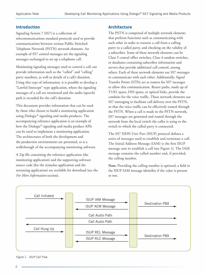
The SS7 ISDN User Part (ISUP) protocol defines a series of messages used to establish and terminate a call. The Initial Address Message (IAM) is the first ISUP message sent to establish a call (see Figure 1). The IAM message contains the called number and, if provided, the calling number.
Note: Providing the calling number is optional; a field in the ISUP IAM message identifies if the value is present or not.
Application Note Developing Call Monitoring Applications Using Dialogic® SS7 Signaling and Media Products
2
Call Initiated
Call Hung Up
Destination PBX
Destination PBX
ISUP IAM Message
ISUP REL Message
Call Audio Path
Call Audio Path
ISUP ACM Message
ISUP RLC Message
Figure 1. ISUP Call Flow
Developing Call Monitoring Applications Using Dialogic® SS7 Signaling and Media Products Application Note
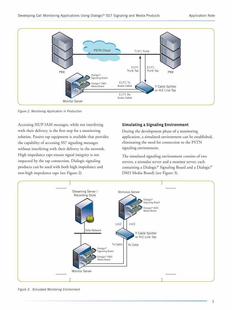
Accessing ISUP IAM messages, while not interfering
with their delivery, is the first step for a monitoring
solution. Passive tap equipment is available that provides
the capability of accessing SS7 signaling messages
without interfering with their delivery in the network.
High impedance taps ensure signal integrity is not
impacted by the tap connection. Dialogic signaling
products can be used with both high impedance and
non-high impedance taps (see Figure 2).
Simulating a Signaling Environment
During the development phase of a monitoring application, a simulated environment can be established, eliminating the need for connection to the PSTN signaling environment.
The simulated signaling environment consists of two servers, a stimulus server and a monitor server, each containing a Dialogic® Signaling Board and a Dialogic® DM3 Media Board) (see Figure 3).
3
PSTN Cloud T1/E1 Trunk
PBXPBX
Monitor Server
Y Cable Splitter or HiZ Line Tap
E1/T1 Tx Audio Cable
E1/T1 Rx Audio Cable
E1/T1 Trunk Tap
E1/T1 Trunk Tap
Dialogic® Signaling Board
Dialogic® DM3 Media Board
Data Network
Stimulus Server
Monitor Server
Streaming Server / Recording Store
Y Cable Splitter or HiZ Line Tap
Rx CableTx Cable
LIU2 LIU3
Dialogic® Signaling Board
Dialogic® DM3 Media Board
Dialogic® Signaling Board
Dialogic® DM3 Media Board
Figure 2. Monitoring Application in Production
Figure 3. Simulated Monitoring Environment
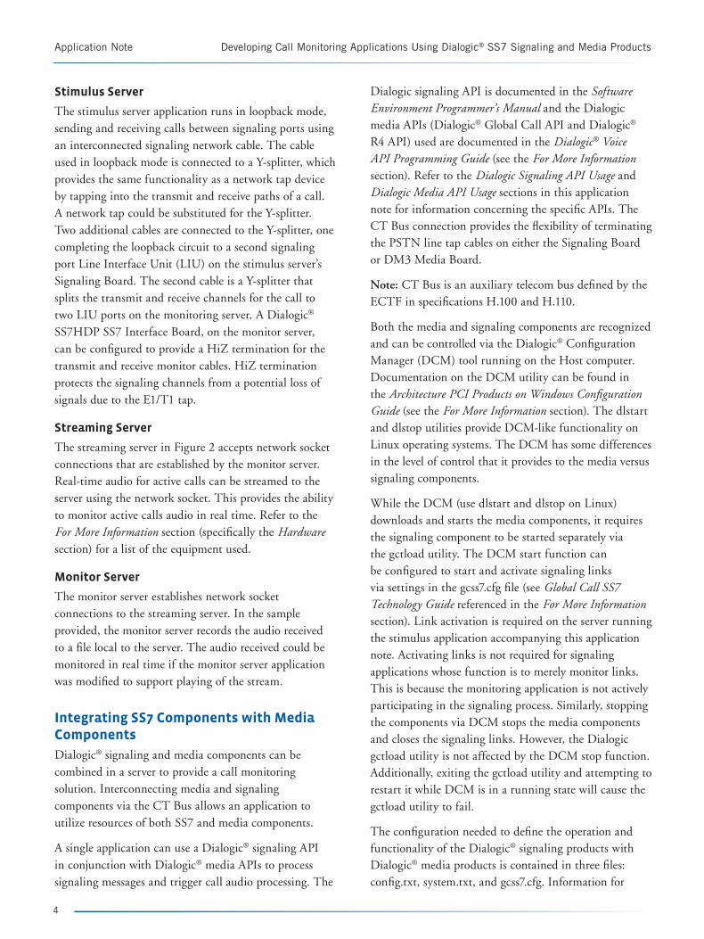
Stimulus Server
The stimulus server application runs in loopback mode, sending and receiving calls between signaling ports using an interconnected signaling network cable. The cable used in loopback mode is connected to a Y-splitter, which provides the same functionality as a network tap device by tapping into the transmit and receive paths of a call. A network tap could be substituted for the Y-splitter. Two additional cables are connected to the Y-splitter, one completing the loopback circuit to a second signaling port Line Interface Unit (LIU) on the stimulus server’s Signaling Board. The second cable is a Y-splitter that splits the transmit and receive channels for the call to two LIU ports on the monitoring server. A Dialogic® SS7HDP SS7 Interface Board, on the monitor server, can be configured to provide a HiZ termination for the transmit and receive monitor cables. HiZ termination protects the signaling channels from a potential loss of signals due to the E1/T1 tap.
Streaming Server
The streaming server in Figure 2 accepts network socket connections that are established by the monitor server. Real-time audio for active calls can be streamed to the server using the network socket. This provides the ability to monitor active calls audio in real time. Refer to the For More Information section (specifically the Hardware section) for a list of the equipment used.
Monitor Server
The monitor server establishes network socket connections to the streaming server. In the sample provided, the monitor server records the audio received to a file local to the server. The audio received could be monitored in real time if the monitor server application was modified to support playing of the stream.
Integrating SS7 Components with Media Components
Dialogic® signaling and media components can be combined in a server to provide a call monitoring solution. Interconnecting media and signaling components via the CT Bus allows an application to utilize resources of both SS7 and media components.
A single application can use a Dialogic® signaling API in conjunction with Dialogic® media APIs to process signaling messages and trigger call audio processing. The
Dialogic signaling API is documented in the Software Environment Programmer’s Manual and the Dialogic media APIs (Dialogic® Global Call API and Dialogic® R4 API) used are documented in the Dialogic® Voice API Programming Guide (see the For More Information section). Refer to the Dialogic Signaling API Usage and Dialogic Media API Usage sections in this application note for information concerning the specific APIs. The CT Bus connection provides the flexibility of terminating the PSTN line tap cables on either the Signaling Board or DM3 Media Board.
Note: CT Bus is an auxiliary telecom bus defined by the ECTF in specifications H.100 and H.110.
Both the media and signaling components are recognized and can be controlled via the Dialogic® Configuration Manager (DCM) tool running on the Host computer. Documentation on the DCM utility can be found in the Architecture PCI Products on Windows Configuration Guide (see the For More Information section). The dlstart and dlstop utilities provide DCM-like functionality on Linux operating systems. The DCM has some differences in the level of control that it provides to the media versus signaling components.
While the DCM (use dlstart and dlstop on Linux) downloads and starts the media components, it requires the signaling component to be started separately via the gctload utility. The DCM start function can be configured to start and activate signaling links via settings in the gcss7.cfg file (see Global Call SS7 Technology Guide referenced in the For More Information section). Link activation is required on the server running the stimulus application accompanying this application note. Activating links is not required for signaling applications whose function is to merely monitor links. This is because the monitoring application is not actively participating in the signaling process. Similarly, stopping the components via DCM stops the media components and closes the signaling links. However, the Dialogic gctload utility is not affected by the DCM stop function. Additionally, exiting the gctload utility and attempting to restart it while DCM is in a running state will cause the gctload utility to fail.
The configuration needed to define the operation and functionality of the Dialogic® signaling products with Dialogic® media products is contained in three files: config.txt, system.txt, and gcss7.cfg. Information for
Application Note Developing Call Monitoring Applications Using Dialogic® SS7 Signaling and Media Products
4
Developing Call Monitoring Applications Using Dialogic® SS7 Signaling and Media Products Application Note
configuring the config.txt and system.txt files is found
in the SS7HD Programmer’s Manual and information
covering the configuration in the gcss7.cfg file is located
in the Global Call SS7 Technology Guide (see the For More Information section).
system.txt
The system.txt file contains information concerning
which signaling protocol modules are loaded and whether
they run on the Signaling Board or on the server hosting
the Signaling Board. The SS7HD Programmer’s Manual contains additional information related to the system.txt
configuration settings. Appendix A has a listing of the
actual system.txt files used by the accompanying reference
application for both the monitor and stimulus servers.
config.txt
The config.txt file is used to set up the configuration of
the T1/E1 interfaces and the operating parameters for
the Signaling Board(s) used. The SS7HD Programmer’s Manual contains additional information related to the
config.txt configuration settings. Appendix A contains
a listing of the actual config.txt files used by the
accompanying reference application for both the monitor
and stimulus servers.
gcss7.cfg
Dialogic® Global Call SS7 implements the Dialogic®
Global Call Software architecture, allowing the Global
Call APIs to be used with the Dialogic signaling
products. The gcss7.cfg file must be configured for the
DCM to recognize and control the Signaling Board
installed.
Although additional modifications are needed in gcss7.cfg,
modifying the following line:
System.Configuration = “None”
to
System.Configuration = “Card”
is the only modification required for DCM to identify
that the Signaling Board is installed in the server.
Additional modifications are related to identifying
directories containing signaling configuration files,
defining logging to be used, and identifying the ISUP
circuit groups controlled by the Signaling Board.
The actual gcss7.cfg files used on both the monitor and stimulus servers in the reference application are included in Appendix B. The files in Appendix B only contain the uncommented lines from the actual configuration files. Actual configuration files are included in the software distribution that can be downloaded (see the For More Information section).
Mapping SS7 Channel Identification Codes to Network Devices
SS7 signaling messages use a Channel Identification Code (CIC) to identify which trunk channel contains the audio for a particular call. The Dialogic media API uses network identifiers and CT Bus time slots to take action on a call. In the reference application instance, that action is to record the call audio using the network transmit time slots of the called and calling party. The application developer needs to provide a mapping of the Dialogic® network device to the CIC information received for a call. The following describes the steps to establish this mapping:
1. Install and configure both media and signaling devices so they appear in the DCM utility and can be stopped and started using this utility.
2. Run an application like the “gc_basic_call_model” demo. This generates an ss7.log file in the directory from which the application was run.
3. Use the ss7trace utility, found in the dialogic\bin directory, to translate the ss7.log into a readable format.
4. The converted ss7.log file identifies the LIUs configured in the config.txt file and identifies both the network name and CT Bus time slot for each of the CICs resident on the configured trunks.
Notes
• Signaling Board LIU numbering starts from LIU 0.
• The translated ss7.log file does not determine whether or not the attached trunk is E1- or T1-based. It contains the network device and CT Bus time slot information for 32 devices per the configured LIU.
• Although building a map of CIC to CT Bus time slot is generally straightforward, building the same map when connected to multiple point codes supplied by multiple PSTN network providers may make the mapping task more difficult.
5
Walkthrough of the Sample Reference Application
This section is intended to provide a walkthrough of the reference application and supporting applications that accompany this document. These applications were developed using Microsoft® Visual Studio® 2003; however, no Microsoft® specific operating system or development environment specific features were used.
The SignalingMonitor application showcases both the Dialogic® signaling and media APIs used for a call monitoring application. This application was developed in C++ with a basic object-oriented design. The design complexity was reduced in order to provide a clear example of the API commands needed.
The following sections contain information to assist developers in gaining a complete understanding of the code base provided.
Overview
The code available for download contains the components for running the simulated call monitoring environment shown in Figure 2. An application runs on each of the servers (stimulus server, streaming server, and monitor server), which are shown in Figure 3.
Stimulus Server
The first server and application is the stimulus server. This server runs a modified copy of the Dialogic® Global Call Software demo, “gc_basic_call_model”. The demo has been modified to simulate a conversation between the called and calling parties on a call. Modifications include the called and calling party instances opening and playing a pre-recorded audio file for a limited duration once the called party answers. Identification of the called and calling parties is defined in the gc_basic_call_model.cfg file.
Note that signaling network devices are identified as “dkBxKy”, where x = 1-4 and y = 1-31. There are 31 possible “y” network device values to cover the situation where E1 trunks are attached to the Signaling Board. DCM and Global Call Software do not attempt to determine whether a T1 or E1 cable is attached. Additionally, DCM and Global Call Software do not identify the trunk channels used for signaling or
synchronization (for E1, channel 16 and channel 0, respectively; and for T1, channel 24 and channel 0, respectively).
Streaming Server
The second server and application is the streaming server. This server runs an application that listens for and accepts socket connect requests received from the data network. In the reference application, the monitoring server application can be configured to open a network connection to the streaming server for the purpose of streaming call audio in real time to this server. The streaming server application records the audio received in a file as verification of the streaming functionality. This application provides the ability for users to listen in on actual calls as they are occurring.
Monitor Server
The third sever is the monitor server that is used to run the SignalingMonitor application. This application utilizes the signaling API and the media API to provide the call monitoring function. Signaling messages are parsed to check for ISUP protocol messages. ISUP IAM messages are parsed to collect called party information and caller information, if available. Receipt of an IAM message also triggers the start of local recording and, if configured, network streaming of the call’s audio. Call audio is streamed to the network address (StreamingIpAddress) and port (StreamingIpPort) identified in the application’s configuration file.
Call recording and network streaming for a call are stopped when an ISUP Release Complete Message (RLC) is received for any active call being monitored. Although not implemented in the sample code provided, the streaming server software could be modified by adding a web-based interface that allows the live call audio to be monitored anywhere on the web.
SignalingMonitor Application Description
Functionality by Class
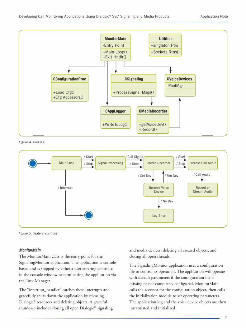
The following sections provide a breakdown of the functionality provided by class in the SignalingMonitor application (see Figure 4). Figure 5 shows the state transitions that the monitoring software goes through when it runs.
Application Note Developing Call Monitoring Applications Using Dialogic® SS7 Signaling and Media Products
6
Developing Call Monitoring Applications Using Dialogic® SS7 Signaling and Media Products Application Note
MonitorMainThe MonitorMain class is the entry point for the
SignalingMonitor application. The application is console-
based and is stopped by either a user entering control-c
in the console window or terminating the application via
the Task Manager.
The “interrupt_handler” catches these interrupts and
gracefully shuts down the application by releasing
Dialogic® resources and deleting objects. A graceful
shutdown includes closing all open Dialogic® signaling
and media devices, deleting all created objects, and
closing all open threads.
The SignalingMonitor application uses a configuration
file to control its operation. The application will operate
with default parameters if the configuration file is
missing or not completely configured. MonitorMain
calls the accessor for the configuration object, then calls
the initialization module to set operating parameters.
The application log and the voice device objects are then
instantiated and initialized.
7
MonitorMain
-Entry Point
+Main Loop()+Exit Hndlr()
CConfigurationProc
+Load Cfg()+Cfg Accessors()
CMediaRecorder
+getVoiceDev()+Record()
CSignaling
+ProcessSignal Msgs()
CVoiceDevices
-PoolMgr
Utilities
+singleton Ptrs
+Sockets Rtns()
CAppLogger
+WriteToLog()
Main Loop
/ Start
/ Stop Signal Processing
/ Start
/ Stop Process Call Audio
/ Call Signal
/ Stop
/ Get Dev / Call Audio
/ Interrupt
/ No Dev
/ Rtn Dev
Media Recorder
Record or Stream Audio
Reserve Voice Device
Log Error
Figure 4. Classes
Figure 5. State Transitions
Finally, the signaling object is instantiated and its method is called to process signaling messages (it enters a loop waiting for an interrupt). This application was developed as a proof of concept for a low volume signaling environment. Developers may need to add additional signaling objects in order to process higher volume signaling environments.
CConfigurationProcThe CConfigurationProc class is the class responsible for reading, parsing, and processing the configuration for the SignalingMonitor application. This class is a singleton (an object designed to have a single instance with a means for global access), and, as a singleton, other classes can globally access the class to get configuration information, reducing parameters passed between classes. The CConfigurationProc opens and reads parameters stored in a configuration file named MonitoringSampleApp.cfg.
All of the information contained in the configuration file is read at once. The parameter values are parsed from the comments, spaces, and parameter names and stored as member variables. Public accessors provide the means for all classes to access parameter values.
Configuration parameters and the functions they provide are listed below:
LoggingEnabled — Turns on and off logging for the application (value is true or false)
LogFileName — Identifies the name of the log file used to log results of the operation
NumberOfRecordingDevices — The number of recording devices to be used to record conversations
StreamingEnabled — Turns on or off streaming of call audio through the network (value is true or false)
StreamingIpAddress — The IP address, in dotted decimal form, to stream call audio to. Only used if StreamingEnabled is true.
StreamingIpPort — The IP port at the StreamingIpAddress to stream call audio to. Only used if StreamingEnabled is true.
RecordSecondFileEnabled — Causes the call audio to be recorded to an additional file (value is true or false)
SecondFilePrefix — Identifies the prefix to be appended to the filename containing the additional call audio
recording. Only used if “RecordSecondFIleEnabled” is set to true.
Parameters can be added to the configuration file with modifications to the “setParametersFromFile” method. Developers would need to add parameter names to the “CommonParameters” array, set an enum value for the parameter, and add an accessor in order to add parameters to the configuration file.
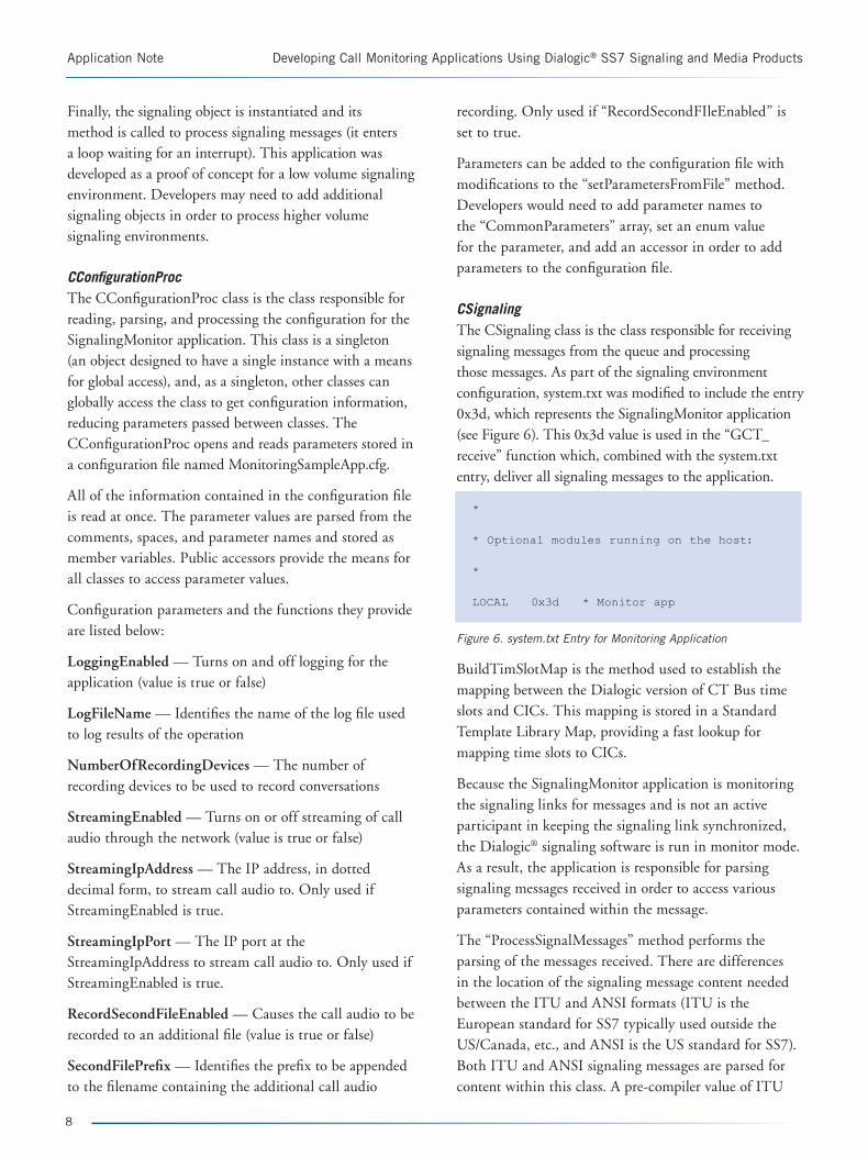
CSignalingThe CSignaling class is the class responsible for receiving signaling messages from the queue and processing those messages. As part of the signaling environment configuration, system.txt was modified to include the entry 0x3d, which represents the SignalingMonitor application (see Figure 6). This 0x3d value is used in the “GCT_receive” function which, combined with the system.txt entry, deliver all signaling messages to the application.
*
* Optional modules running on the host:
*
LOCAL 0x3d * Monitor app
Figure 6. system.txt Entry for Monitoring Application
BuildTimSlotMap is the method used to establish the mapping between the Dialogic version of CT Bus time slots and CICs. This mapping is stored in a Standard Template Library Map, providing a fast lookup for mapping time slots to CICs.
Because the SignalingMonitor application is monitoring the signaling links for messages and is not an active participant in keeping the signaling link synchronized, the Dialogic® signaling software is run in monitor mode. As a result, the application is responsible for parsing signaling messages received in order to access various parameters contained within the message.
The “ProcessSignalMessages” method performs the parsing of the messages received. There are differences in the location of the signaling message content needed between the ITU and ANSI formats (ITU is the European standard for SS7 typically used outside the US/Canada, etc., and ANSI is the US standard for SS7). Both ITU and ANSI signaling messages are parsed for content within this class. A pre-compiler value of ITU
Application Note Developing Call Monitoring Applications Using Dialogic® SS7 Signaling and Media Products
8
Developing Call Monitoring Applications Using Dialogic® SS7 Signaling and Media Products Application Note
causes signaling messages to be parsed using the ITU
format. Not having the pre-compiler value set triggers the
application to parse the messages using the ANSI format.
For demonstration purposes, the ProcessSignalMessages
method is run in a separate thread of execution. As
messages arrive, they are pushed onto a standard template
library queue and a semaphore notification is sent out
to alert the parsing thread to process the message. The
parsing thread, ProcessSignalMessages, then pulls the
signaling message from the queue, parses it, and takes
action based on the message type. Additional message
parsing threads used to deal with higher message
volumes are defined in the constructor and cleaned up
in the destructor. The Boost C++ libraries (see the For
More Information section) are used for the thread and
semaphore capabilities provided in this class due to their
platform independence and their robust implementation.
The ProcessSignalMessages thread has a one-to-one
relationship with the “CMediaRecorder” class. This one-
to-one relationship can reduce the class complexity by
eliminating the need for state checking. Additional state
machines and “ProcessSignalThreads” may be needed in a
production environment containing multiple signaling links.
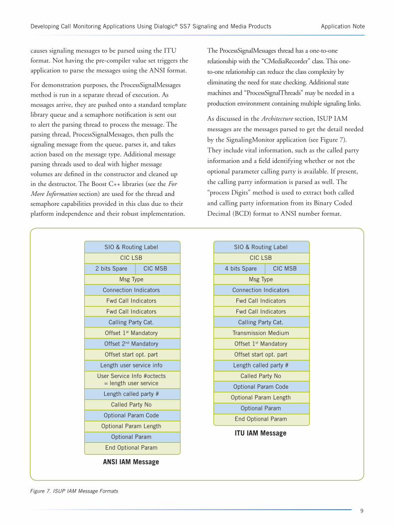
As discussed in the Architecture section, ISUP IAM
messages are the messages parsed to get the detail needed
by the SignalingMonitor application (see Figure 7).
They include vital information, such as the called party
information and a field identifying whether or not the
optional parameter calling party is available. If present,
the calling party information is parsed as well. The
“process Digits” method is used to extract both called
and calling party information from its Binary Coded
Decimal (BCD) format to ANSI number format.
9
SIO & Routing Label
CIC LSB
2 bits Spare CIC MSB
Msg Type
Connection Indicators
Fwd Call Indicators
Fwd Call Indicators
Calling Party Cat.
Offset 1st Mandatory
Offset 2nd Mandatory
Offset start opt. part
Length user service info
User Service Info #octects= length user service
Length called party #
Called Party No
Optional Param Code
Optional Param Length
Optional Param
End Optional Param
ANSI IAM Message
SIO & Routing Label
CIC LSB
4 bits Spare CIC MSB
Msg Type
Connection Indicators
Fwd Call Indicators
Fwd Call Indicators
Calling Party Cat.
Transmission Medium
Offset 1st Mandatory
Offset start opt. part
Length called party #
Called Party No
Optional Param Code
Optional Param Length
Optional Param
End Optional Param
ITU IAM Message
Figure 7. ISUP IAM Message Formats
When an interrupt has been detected in the application, the destructor for the “CSignaling” class sends a shutdown metaphor to the thread it created. The destructor then joins that thread such that the shutdown of the thread completes before the destructor exits. Each added thread to the application should be joined in the destructor so that proper shutdown occurs.
CMediaRecorderThe “CMediaRecorder” class is responsible for performing the media functions related to handling the call audio for the monitored phone call. Functionality provided by this class is dependant on the configuration defined. The functions include recording to a primary and secondary audio file, as well as streaming to a network address/port.
The “StartRecording” method is called by the CSignaling class to begin recording and streaming audio for a monitored call. “StopRecording” is called when the ISUP Release Complete Message (RLC) is received for a particular call. The “StopRecording” method closes all open recording files and the streaming network socket, if that is open for that particular call.
A single Dialogic® voice device is used to synchronize and record both halves of a conversation to an 8 bit, 8 kHz VOX file. The “processCallAudio” method is a custom Dialogic® output method defined in the dx_setuio function. This method provides the recording and the network streaming of call audio for those calls to be monitored. Because the dx_setuio function requires the definition of all custom I/O routines (read, write, seek), the “CRecordRead” and the “CRecordSeek” methods were added. These routines simply return the size information passed in to them.
CVoiceDevicesThe “CVoiceDevices” class is responsible for opening the Dialogic® voice devices and for maintaining a pool
of voice devices for use by the “CMediaRecorder” class.
This object is a singleton object and is instantiated in
“MonitorMain” on startup. The “InitializeVoiceDevices”
method opens the number of Dialogic voice devices
defined in the configuration file. If this value is not set,
31 voice devices are opened.
As each voice device is opened, it is added to a standard
template library-based list of available devices. When
the “CMediaRecorder” class requests a voice device to
record a monitored call, the “GetVoiceDevice” method
pulls the voice device handle from the head of the
available list and adds the handle to a list of devices
in use. When monitoring of a call is complete, the
“ReturnVoiceDevice” method is called moving the voice
device from the in-use list to the available list.
Upon shutdown, the destructor walks through the list
of available devices, closing each device on the list. The
in-use list is then traversed, with the voice devices being
stopped before being closed.
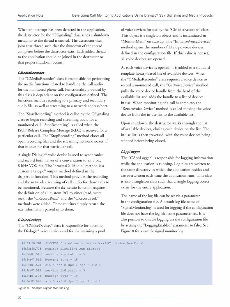
CAppLogger
The “CAppLogger” is responsible for logging information
while the application is running. Log files are written to
the same directory in which the application resides and
are overwritten each time the application runs. This class
is also a singleton class such that a single logging object
exists for the entire application.
The name of the log file can be set via a parameter
in the configuration file. A default log file name of
“SignalMonitor.log” is used for logging if the configuration
file does not have the log file name parameter set. It is
also possible to disable logging via the configuration file
by setting the “LoggingEnabled” parameter to false. See
Figure 8 for a sample signal monitor log.
Application Note Developing Call Monitoring Applications Using Dialogic® SS7 Signaling and Media Products
10
16:23:58.281 SUCCESS Opened voice devicedxxxB1C1 device handle =1
16:23:58.703 Monitor Signaling App Started
16:24:07.546 service indicator = 5
16:24:07.562 Message Type = 18
16:24:07.578 sio 5 ssf 8 dpc 1 opc 3 cic 1
16:24:07.593 service indicator = 5
16:24:07.609 Message Type = 19
16:24:07.625 sio 5 ssf 8 dpc 3 opc 1 cic 1
Figure 8. Sample Signal Monitor Log

Developing Call Monitoring Applications Using Dialogic® SS7 Signaling and Media Products Application Note
UtilitiesThe “Utilities” module is not a class; rather, it contains common methods used in other classes within the application. One of the functions provided is the global point of access methods for the various singleton classes. These global points of access first check to see if an object of the type of a specific class has been instantiated. If a singleton object has previously been instantiated, a pointer to the object is returned. Otherwise the object is instantiated prior to its pointer being returned.
Other significant utility modules provide the network socket support for the application. Socket open, close, and the means to send data over a TCP socket are provided within this module. Lastly, a time stamp method is provided to be used by the logging function to provide timestamps on the log file entries.
Dialogic® Signaling API Usage
A limited number of Dialogic signaling API’s functions are used within the SignalingMonitor application. These functions are documented in the Software Environment Programmer’s Manual. The first function used is “GCT_receive”, which has a parameter of the applications the process ID defined within the system.txt file. This call is a blocking call returning only when there is a signaling message in the queue. After the messages have been queued to the worker thread for processing, the “GCT_send” function is used to send the message to the Dialogic® signaling logger. This frees the message and its
memory usage from the signaling message queue, which
is a necessary step. An alternative to this would involve
using the “relm” function to release the message from the
queue and free the related memory.
The “unpackbits” macro is used in parsing the signaling
packets received in the signaling queue. This macro
converts the signaling packet data for a specified size into
a human readable format.
Dialogic® Media API Usage
A limited number of the Dialogic media API’s functions
are used, mainly to provide the recording functionality
for monitored calls. The “CVoiceDevice” class uses
the “dx_open” function to open the voice devices and
“dx_close” function to close open voice devices. On
shutdown, the “dx_stopch” function is used to stop the
voice device before it is closed.
The “CMediaRecorder” is the only other class to use
the Dialogic media APIs. A call to the “dx_setuio”
function is used to establish the custom output method
used to record audio to multiple files and stream into
the network. The “dx_mreciottdata” function is used to
mix the two halves of a phone conversation into a single
media stream. Finally, “dx_stopch” and “dx_unlisten”
functions are used by the “StopRecording” method to
stop the audio and listening on the two CT Bus time
slots being recorded.
11
Appendix A: Signaling Configuration
Stimulus/Call Simulation Server
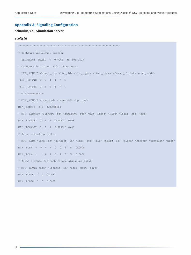
config.txt
************************************************************************
* Configure individual boards:
SEPTELPCI _ BOARD 0 0x0042 ss7.dc3 ISUP
* Configure individual E1/T1 interfaces:
* LIU _ CONFIG <board _ id> <liu _ id> <liu _ type> <line _ code> <frame _ format> <crc _ mode>
LIU _ CONFIG 0 2 4 4 7 4
LIU _ CONFIG 0 3 4 4 7 4
* MTP Parameters:
* MTP _ CONFIG <reserved> <reserved> <options>
MTP _ CONFIG 0 0 0x00040f00
* MTP _ LINKSET <linkset _ id> <adjacent _ spc> <num _ links> <flags> <local _ spc> <ssf>
MTP _ LINKSET 0 1 1 0x0000 3 0x08
MTP _ LINKSET 1 3 1 0x0000 1 0x08
* Define signaling links:
* MTP _ LINK <link _ id> <linkset _ id> <link _ ref> <slc> <board _ id> <blink> <stream> <timeslot> <flags>
MTP _ LINK 0 0 0 0 0 0 2 24 0x0006
MTP _ LINK 1 1 0 0 0 1 3 24 0x0006
* Define a route for each remote signaling point:
* MTP _ ROUTE <dpc> <linkset _ id> <user _ part _ mask>
MTP _ ROUTE 3 1 0x0020
MTP _ ROUTE 1 0 0x0020
Application Note Developing Call Monitoring Applications Using Dialogic® SS7 Signaling and Media Products
12

Developing Call Monitoring Applications Using Dialogic® SS7 Signaling and Media Products Application Note
system.txt
************************************************************************
* Essential modules running on host:
*
LOCAL 0x20 * ssd/ssds - Board interface task
LOCAL 0x00 * tim _ nt - Timer task
* Optional modules running on the host:
*
LOCAL 0xcf * s7 _ mgt - Management/config task
LOCAL 0xef * s7 _ log
LOCAL 0x3d * ctu - Example user part task
LOCAL 0x4d * global call ss7
*
* Modules running on the board (all redirected via ssd):
*
REDIRECT 0x23 0x20 * ISUP module
REDIRECT 0x22 0x20 * MTP3 module
REDIRECT 0x71 0x20 * MTP2 module
REDIRECT 0x10 0x20 * CT bus/Clocking control module
REDIRECT 0x8e 0x20 * On-board management module
* Redirection of status indications:
REDIRECT 0xdf 0xef * LIU/MTP2 status messages -> s7 _ log
FORK _ PROCESS ssds.exe -d
FORK _ PROCESS tim _ nt.exe
FORK _ PROCESS tick _ nt.exe
FORK _ PROCESS s7 _ mgt.exe -d -i0x4d
FORK _ PROCESS s7 _ log.exe -td -m0xef -o0xff1f -fss7.log
*
13
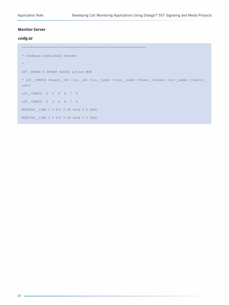
Monitor Server
config.txt
************************************************************************
* Configure individual boards:
*
SS7 _ BOARD 0 SS7HDP 0x0043 ss7.dc4 MON
* LIU _ CONFIG <board _ id> <liu _ id> <liu _ type> <line _ code> <frame _ format> <crc _ mode> [<build _
out>]
LIU _ CONFIG 0 2 4 4 7 4
LIU _ CONFIG 0 3 4 4 7 4
MONITOR _ LINK 1 0 0-1 2 24 0x3d 0 0 0x00
MONITOR _ LINK 2 0 0-2 3 24 0x3d 0 0 0x00
Application Note Developing Call Monitoring Applications Using Dialogic® SS7 Signaling and Media Products
14
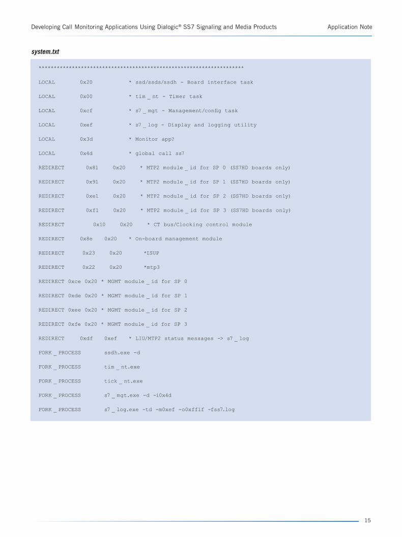
Developing Call Monitoring Applications Using Dialogic® SS7 Signaling and Media Products Application Note
system.txt
********************************************************************
LOCAL 0x20 * ssd/ssds/ssdh - Board interface task
LOCAL 0x00 * tim _ nt - Timer task
LOCAL 0xcf * s7 _ mgt - Management/config task
LOCAL 0xef * s7 _ log - Display and logging utility
LOCAL 0x3d * Monitor app?
LOCAL 0x4d * global call ss7
REDIRECT 0x81 0x20 * MTP2 module _ id for SP 0 (SS7HD boards only)
REDIRECT 0x91 0x20 * MTP2 module _ id for SP 1 (SS7HD boards only)
REDIRECT 0xe1 0x20 * MTP2 module _ id for SP 2 (SS7HD boards only)
REDIRECT 0xf1 0x20 * MTP2 module _ id for SP 3 (SS7HD boards only)
REDIRECT 0x10 0x20 * CT bus/Clocking control module
REDIRECT 0x8e 0x20 * On-board management module
REDIRECT 0x23 0x20 *ISUP
REDIRECT 0x22 0x20 *mtp3
REDIRECT 0xce 0x20 * MGMT module _ id for SP 0
REDIRECT 0xde 0x20 * MGMT module _ id for SP 1
REDIRECT 0xee 0x20 * MGMT module _ id for SP 2
REDIRECT 0xfe 0x20 * MGMT module _ id for SP 3
REDIRECT 0xdf 0xef * LIU/MTP2 status messages -> s7 _ log
FORK _ PROCESS ssdh.exe -d
FORK _ PROCESS tim _ nt.exe
FORK _ PROCESS tick _ nt.exe
FORK _ PROCESS s7 _ mgt.exe -d -i0x4d
FORK _ PROCESS s7 _ log.exe -td -m0xef -o0xff1f -fss7.log
15

Appendix B. Media Configuration
Stimulus Server – gcss7.cfg
#############################################
System.Configuration = “Card”
Library.LogFile = “ss7.log”
Library.LogLevels = “All”
Library.LogMaxSize = 2000
Service.LogLevels = “All”
Service.LogMaxSize = 2000
Service.GCTLOAD _ Control = “No”
Service.GCTLOAD _ Path = “c:\septel”
Service.ModuleID = 0x4d
Service.WatchDogMaxTime = 0
SeptelCard.ConfigDir = “c:\septel”
SeptelCard.Auto _ Links _ Activation = “All”
SIU.HostID = 0
# CGrp <gid> <”trunk _ name”> [<base _ TS> [<”Pref _ SIU”>]]
CGrp 0 dkB1
CGrp 1 dkB2
Application Note Developing Call Monitoring Applications Using Dialogic® SS7 Signaling and Media Products
16

Developing Call Monitoring Applications Using Dialogic® SS7 Signaling and Media Products Application Note
Monitor Server – gcss7.cfg
#############################################
# Format: String - [“None”, “Card”, “SIU”, “DualSIU”, “UserPart”]
System.Configuration = “Card”
Library.LogFile = “ss7.log”
Library.LogLevels = “All”
Library.LogMaxSize = 2000
Service.LogLevels = “All”
Service.LogMaxSize = 2000
Service.GCTLOAD _ Control = “No”
Service.GCTLOAD _ Path = “c:\septel”
Service.ModuleID = 0x4d
Service.WatchDogMaxTime = 0
SeptelCard.ConfigDir = “c:\septel”
SeptelCard.Auto _ Links _ Activation = “None”
SIU.HostID = 0
ClearGrp dkB1 0x7fffff
ClearGrp dkB2 0x7fffff
17
Acronyms
CIC Channel Identification Code. Identifies the trunk channel containing the audio for a call.
CT Bus Computer Telephony. An auxiliary telecom bus defined by the ECTF in specifications H.100 and H.110.
IAM Initial Address Message. ISUP message used to signal the start of a call.
ISUP ISDN User Part. Signaling protocol used to signal for call setup and termination.
LIU Line Interface Units
RLC Release Complete Message. ISUP message used to signal a hang up complete for a call.
PSTN Public Switched Telephone Network
SS7 Signaling System 7. Worldwide commonly used protocol for communication and control in the Public Switched Telephone Network.
Singleton object Ensures the object has only one instance and global access is provided to it.
Standard Template Library A software library included in the C++ standard library.
For More Information
A Zip file containing the source code and reference application and supporting applications’ source code can be downloaded at http://www.dialogic.com/goto/?10970
Architecture PCI Products on Windows Configuration Guide — http://www.dialogic.com/manuals/docs/dm3_pci_config_win_v1.pdf
Dialogic® Voice API Programming Guide — http://www.dialogic.com/manuals/docs/voice_programming_win_v2.pdf
Global Call SS7 Technology Guide — http://www.dialogic.com/manuals/docs/globalcall_for_ss7_v5.pdf
Software Environment Programmer’s Manual — http://resource.dialogic.com/telecom/support/ss7/cd/GenericInfo/GeneralDocumentation/U10SSS05-SwEnv-PM.pdf
SS7HD Programmer’s Manual — http://resource.dialogic.com/telecom/support/ss7/cd/ProductSpecific/SS7HD/Documentation/SS7HD-PM-Iss008.pdf
Application Note Developing Call Monitoring Applications Using Dialogic® SS7 Signaling and Media Products
18
Developing Call Monitoring Applications Using Dialogic® SS7 Signaling and Media Products Application Note
Materials List for Reference Application
SoftwareBoost version 1.33.1 — Used to provide threading and semaphore capabilities in sample application http://boost.org/
Dialogic® Signaling Software — Windows® Development Package and User Part Development Package http://www.dialogic.com/support/helpweb/signaling/software3.htm
Dialogic® Signaling Software Documentation — http://www.dialogic.com/support/helpweb/signaling/software4.htm
Dialogic® Media Software — Documentation is installed from the downloaded development kit http://www.dialogic.com/products/tdm_boards/system_release_software/System_Release_60_Win.htm
Microsoft® Visual Studio® 2003 — Development environment
HardwareStimulus and Call Simulation Server
Dialogic® SPCI4S Signaling Board and Dialogic® SPCI4 SS7 Interface Board (Dialogic® SPCI2S SS7 Interface Board could also be used) — http://www.dialogic.com/products/signalingip_ss7components/Signaling_Boards_SPC.htm
Dialogic® DM3 Media Board (must have voice capabilities) — http://www.dialogic.com/products/tdm_boards/media_processing/default.htm
T1/E1 splitter and Y-cable
Monitor Server
Dialogic® SS7HDP SS7 Interface Board — http://www.dialogic.com/products/signalingip_ss7components/Signaling_Boards_SS7HDP.htm
Also, could use Compact PCI version: Dialogic® SS7HDC SS7 Interface Board — http://www.dialogic.com/products/signalingip_ss7components/Signaling_Boards_SS7HDC.htm
Dialogic® DM3 Media Board (must have voice capabilities) — http://www.dialogic.com/products/tdm_boards/media_processing/default.htm
19
www.dialogic.com
To learn more about Dialogic® products, go to www.dialogic.com.
Dialogic Corporation9800 Cavendish Blvd., 5th floorMontreal, QuebecCANADA H4M 2V9
INFORMATION IN THIS DOCUMENT IS PROVIDED IN CONNECTION WITH PRODUCTS OF DIALOGIC CORPORATION OR ITS SUBSIDIARIES (“DIALOGIC”). NO LICENSE, EXPRESS OR IMPLIED, BY ESTOPPEL OR OTHERWISE, TO ANY INTELLECTUAL PROPERTY RIGHTS IS GRANTED BY THIS DOCUMENT. EXCEPT AS PROVIDED IN A SIGNED AGREEMENT BETWEEN YOU AND DIALOGIC, DIALOGIC ASSUMES NO LIABILITY WHATSOEVER, AND DIALOGIC DISCLAIMS ANY EXPRESS OR IMPLIED WARRANTY, RELATING TO SALE AND/OR USE OF DIALOGIC® PRODUCTS INCLUDING LIABILITY OR WARRANTIES RELATING TO FITNESS FOR A PARTICULAR PURPOSE, MERCHANTABILITY, OR INFRINGEMENT OF ANY INTELLECTUAL PROPERTY RIGHT OF A THIRD PARTY.
Dialogic products are not intended for use in medical, life saving, life sustaining, critical control or safety systems, or in nuclear facility applications.
Dialogic may make changes to specifications, product descriptions, and plans at any time, without notice.
Dialogic is a registered trademark of Dialogic Corporation. Dialogic”s trademarks may be used publicly only with permission from Dialogic. Such permission may only be granted by Dialogic”s legal department at 9800 Cavendish Blvd., 5th Floor, Montreal, Quebec, Canada H4M 2V9. Any authorized use of Dialogic”s trademarks will be subject to full respect of the trademark guidelines published by Dialogic from time to time and any use of Dialogic”s trademarks requires proper acknowl-edgement.
Microsoft, Windows, and Visual Studio are registered trademarks of Microsoft Corporation in the United States and/or other countries. Other names of actual compa-nies and products mentioned herein are the trademarks of their respective owners. Dialogic encourages all users of its products to procure all necessary intellectual property licenses required to implement their concepts or applications, which licenses may vary from country to country.
This document discusses one or more open source products, systems and/or releases. Dialogic is not responsible for your decision to use open source in connection with Dialogic products (including without limitation those referred to herein), nor is Dialogic responsible for any present or future effects such usage might have, including without limitation effects on your products, your business, or your intellectual property rights.
Copyright © 2008 Dialogic Corporation All rights reserved. 03/08 10968-01


