Embed Size (px)
Citation preview
How can I …Develop a time stamping application in PlantStruxure?
Develop your project
System Technical GuideTime Stamping solutions

Disclaimer
This document is not comprehensive for any systems using the given architecture
and does not absolve users of their duty to uphold the safety requirements for the
equipment used in their systems or compliance with both national or international
safety laws and regulations.
It is assumed that readers already know how to use the products described in this
document.
This document does not replace any specific product documentation.
3
The STG Collection
System Technical Guides (STG) are designed to help project engineers and Alliance
System Integrators during the development of a project. The STGs support users
during the architecture selection and the project execution (design, configuration,
implementation and operation) phases with an introduction to the system operating
modes.
Each STG is a starter kit that provides users with:
• Technical documentation
• Application examples
• Object libraries
Each STG addresses one or several customer challenges within the proposed
solution using the offer from Schneider Electric.
All explanations and applications have been developed by both Schneider Electric
experts and system integrators in our solution labs. The contributions from the system
integrators help the kit’s content meet the expectations of our users.
All STGs are illustrated with industry-specific applications to give more concrete
examples of the methodology.
STGs are not intended to be used as substitutes for the technical documentation
related to the individual components, but rather to complement these materials and
training.
Development Environment
Each STG has been developed in one of our solution platform labs using a typical
PlantStruxure architecture.
PlantStruxure, the Process Automation System from Schneider Electric, is a
collaborative system that allows industrial and infrastructure companies to meet their
automation needs while also addressing growing energy management requirements.
Within a single environment, measured energy and process data can be analyzed to
help build an optimized plant.
4

Table of Contents
Quick Start Guide .....................................................................7
1. Introduction...........................................................................9
1.1. Purpose ........................................................................................................................................................ 9
1.2. Introduction to time stamping ...................................................................................................................... 9
1.3. Challenges.................................................................................................................................................. 12
1.4. Prerequisites .............................................................................................................................................. 12
1.5. Methodology............................................................................................................................................... 12
1.6. Limitation................................................................................................................................................... 13
2. Selection..............................................................................15
2.1. Selection criteria ........................................................................................................................................ 15
2.2. Selection steps ............................................................................................................................................ 15
2.3. Solution list ................................................................................................................................................ 17
3. Design..................................................................................21
3.1. System hardware design............................................................................................................................. 21
3.2. System software design .............................................................................................................................. 23
3.3. DFB design ................................................................................................................................................ 24
3.4. SCADA design............................................................................................................................................ 37
4. Configuration......................................................................41
4.1. Time stamped by module............................................................................................................................ 41
4.2. Time stamped by program.......................................................................................................................... 44
5. Implementation...................................................................47
5.1. PAC............................................................................................................................................................ 47
5.2. SCADA ....................................................................................................................................................... 50
5
6
6. Operation.............................................................................53
6.1 Time stamping diagnostics .......................................................................................................................... 53
6.2 Time stamping alarms................................................................................................................................. 54
7. Hydro power plant example ..............................................55
7.1. Introduction to the hydro power plant process .......................................................................................... 55
7.2. Application background ............................................................................................................................. 56
7.3. System architecture .................................................................................................................................... 57
7.4. PAC application......................................................................................................................................... 58
7.5. SCADA application .................................................................................................................................... 60
7.7. Device list................................................................................................................................................... 63
Appendix .................................................................................65
Abbreviations .................................................................................................................................................... 65
Quick Start Guide
Quick Start Guide
The goal of this System Technical Guide (STG) is to provide recommendations,
guidelines, and examples to help develop a time stamping solution effectively and
reliably for a typical PlantStruxure architecture.
To get the most out of this STG, please consider the following suggestions::
- If this is the first time you are using the time stamping application, we recommend
that you read the entire STG before proceeding.
- If you are already familiar with time stamping technology and want to define a
solution for your application, you can start at Chapter 2.
- If your solution architecture is defined and you want to setup your application, you
can start at Chapter 3.
- If you already have knowledge about implementing time stamping applications
with Schneider products and you want to see some real examples, please go to
Chapter 7 of this STG.
7

1-Introduction
8
1-Introduction
1. Introduction
1.1. Purpose
With continuous developments in industry and technology, more and more
automation systems are being implemented in different fields. For better control and
maintenance of complex systems, end users of these automation systems require
processing data with time stamps.
This guide proposes a method to implement a time stamping solution using a
Programmable Automation Controller (PAC) and a SCADA system. Moreover, this
STG suggests the best practices to follow to take advantage of system openness
while reducing the risks of misuse and misunderstandings.
The recommendations and guidelines provided in the following chapters are generic
and targeted at time stamping applications such as tracking a sequence of events
(SOE) or time stamping alarms. However, we use the specific example of a sequence
of events (SOE) function in a hydro power plant to illustrate a time stamping
application in a process control system.
1.2. Introduction to time stamping
1.2.1 What is time stamping?
A time stamp in an automation system is the time information of when a signal event
occurred. It is recorded by the control units in a consistent format. The function of
recording the time stamps is called time stamping.
Time stamping is an important function for tracking processes in some automation
systems, such as hydro power plant control and oil pipeline control. This function
provides operators with a method to better identify process sequences in a large and
complex system, to fine tune protection and control schemes, and improve overall
system reliability. One of the most important applications of time stamping is to help
track down the root causes after a system error is detected.
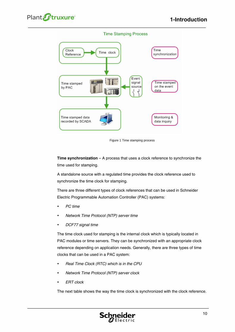
1.2.2 What is the process flow of the time stamping function?
The time stamping function in a process automation system can be implemented in
three steps: time sourcing, stamping time on the event data, and monitoring & inquiry.
The following flow chart shows the time stamping process:
9
1-Introduction
Figure 1 Time stamping process
Time synchronization – A process that uses a clock reference to synchronize the
time used for stamping.
A standalone source with a regulated time provides the clock reference used to
synchronize the time clock for stamping.
There are three different types of clock references that can be used in Schneider
Electric Programmable Automation Controller (PAC) systems:
PC time
Network Time Protocol (NTP) server time
DCF77 signal time
The time clock used for stamping is the internal clock which is typically located in
PAC modules or time servers. They can be synchronized with an appropriate clock
reference depending on application needs. Generally, there are three types of time
clocks that can be used in a PAC system:
Real Time Clock (RTC) which is in the CPU
Network Time Protocol (NTP) server clock
ERT clock
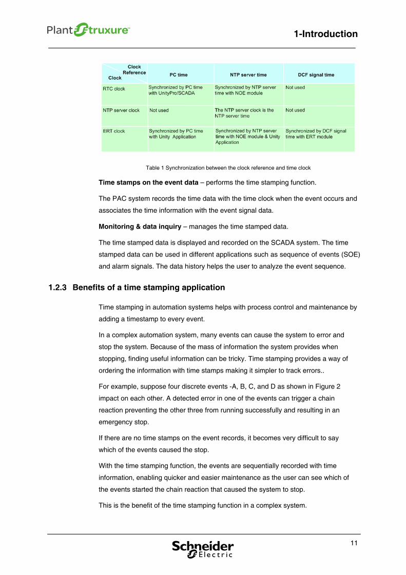
The next table shows the way the time clock is synchronized with the clock reference.
10
1-Introduction
Table 1 Synchronization between the clock reference and time clock
Time stamps on the event data – performs the time stamping function.
The PAC system records the time data with the time clock when the event occurs and
associates the time information with the event signal data.
Monitoring & data inquiry – manages the time stamped data.
The time stamped data is displayed and recorded on the SCADA system. The time
stamped data can be used in different applications such as sequence of events (SOE)
and alarm signals. The data history helps the user to analyze the event sequence.
1.2.3 Benefits of a time stamping application
Time stamping in automation systems helps with process control and maintenance by
adding a timestamp to every event.
In a complex automation system, many events can cause the system to error and
stop the system. Because of the mass of information the system provides when
stopping, finding useful information can be tricky. Time stamping provides a way of
ordering the information with time stamps making it simpler to track errors..
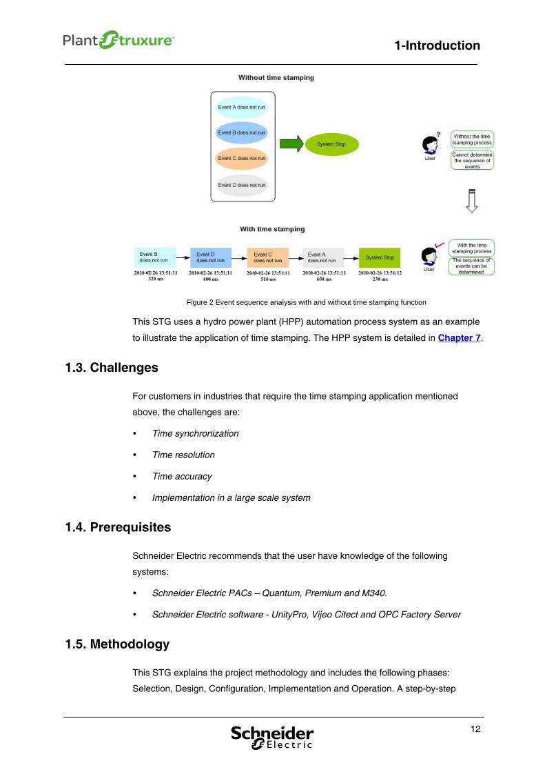
For example, suppose four discrete events -A, B, C, and D as shown in Figure 2
impact on each other. A detected error in one of the events can trigger a chain
reaction preventing the other three from running successfully and resulting in an
emergency stop.
If there are no time stamps on the event records, it becomes very difficult to say
which of the events caused the stop.
With the time stamping function, the events are sequentially recorded with time
information, enabling quicker and easier maintenance as the user can see which of
the events started the chain reaction that caused the system to stop.
This is the benefit of the time stamping function in a complex system.
11
1-Introduction
Figure 2 Event sequence analysis with and without time stamping function
This STG uses a hydro power plant (HPP) automation process system as an example
to illustrate the application of time stamping. The HPP system is detailed in Chapter 7.
1.3. Challenges
For customers in industries that require the time stamping application mentioned
above, the challenges are:
Time synchronization
Time resolution
Time accuracy
Implementation in a large scale system
1.4. Prerequisites
Schneider Electric recommends that the user have knowledge of the following
systems:
Schneider Electric PACs – Quantum, Premium and M340.
Schneider Electric software - UnityPro, Vijeo Citect and OPC Factory Server
1.5. Methodology
This STG explains the project methodology and includes the following phases:
Selection, Design, Configuration, Implementation and Operation. A step-by-step
12
1-Introduction
13
methodology is provided to create a time stamping application. Here is an overview of
this method:
Selection: In this phase, you will decide the selection criteria and steps that will
guide you to select the most appropriate solution for your application
requirements.
Design: This phase comprises four main parts:
System hardware design: how to develop the time stamping system
hardware.
System software design: how to develop time stamping with Schneider
Electric software.
Derived Function Block (DFB) design: provide a package of the DFBs for
the time stamping application.
SCADA design: how to develop Vijeo Citect time stamping genies.
Configuration: This phase explains how to set up the time stamping application:
How to set up time clock synchronization with references
How to set up a time stamping solution by module
How to set up a time stamping solution by program
Implementation: This phase explains the programming requirements:
The PAC part explains how to set up the time stamping sections.
The SCADA part explains how to set up the Vijeo Citect time stamping
genies and alarms.
Operation: This phase presents the capabilities of the final SCADA application:
How to use Vijeo Citect time stamping genies
How to use the time stamping alarms
1.6. Limitation
The accuracy of timestamps relies on the accuracy of the clock reference. It is also
impacted by the transmission mode. For example, when the CPU RTC gets the time
from the NTP server, the time is delayed by the transmission through the network. A
method must be developed to calculate the delay and adjust the clock reference as
needed. This is not in the scope of this STG. For the Purposes of this guide, we
assume that the time used for time stamping does not suffer any delay.
2-Selection
14
2-Selection
2. Selection
This chapter describes the selection of the components needed to build a time
stamping application and provides a solution list.
2.1. Selection criteria
Each automation control project has specific requirements and constraints, such as
the size of the plant, control complexity, and project budget. The time stamping
resolution is a very important requirement of the project. The requirements and
constraints defined in the project specification are used as guidelines to select the
time stamping solution. There are three criteria for the time stamping application
selection:
Time resolution
System scale (complexity)
Cost
2.2. Selection steps
According to the selection criteria, the time stamping solution is developed in four
steps:
Selecting a time stamping method and mode
Selecting a PAC platform
Selecting an I/O architecture
Selecting a CPU task mode
2.2.1. Selecting a time stamping method and mode
Two different time stamping methods can be used, time stamped by module or time
stamped by program.
15
2-Selection
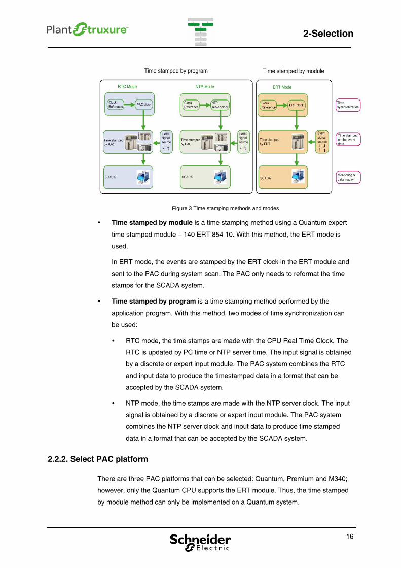
Figure 3 Time stamping methods and modes
Time stamped by module is a time stamping method using a Quantum expert
time stamped module – 140 ERT 854 10. With this method, the ERT mode is
used.
In ERT mode, the events are stamped by the ERT clock in the ERT module and
sent to the PAC during system scan. The PAC only needs to reformat the time
stamps for the SCADA system.
Time stamped by program is a time stamping method performed by the
application program. With this method, two modes of time synchronization can
be used:
RTC mode, the time stamps are made with the CPU Real Time Clock. The
RTC is updated by PC time or NTP server time. The input signal is obtained
by a discrete or expert input module. The PAC system combines the RTC
and input data to produce the timestamped data in a format that can be
accepted by the SCADA system.
NTP mode, the time stamps are made with the NTP server clock. The input
signal is obtained by a discrete or expert input module. The PAC system
combines the NTP server clock and input data to produce time stamped
data in a format that can be accepted by the SCADA system.
2.2.2. Select PAC platform
There are three PAC platforms that can be selected: Quantum, Premium and M340;
however, only the Quantum CPU supports the ERT module. Thus, the time stamped
by module method can only be implemented on a Quantum system.
16
2-Selection
2.2.3. Select I/O architecture
Three I/O architectures can be selected: local I/O, remote I/O and distributed I/O.
Systems with local I/O can achieve high resolution time stamps. For remote I/O and
distributed I/O, the time stamp resolution is limited by the PAC MAST task scan cycle.
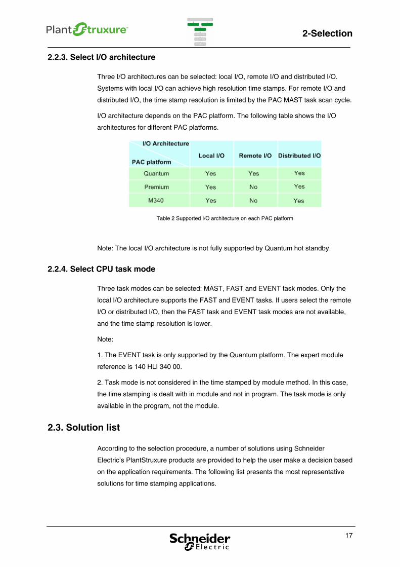
I/O architecture depends on the PAC platform. The following table shows the I/O
architectures for different PAC platforms.
Table 2 Supported I/O architecture on each PAC platform
Note: The local I/O architecture is not fully supported by Quantum hot standby.
2.2.4. Select CPU task mode
Three task modes can be selected: MAST, FAST and EVENT task modes. Only the
local I/O architecture supports the FAST and EVENT tasks. If users select the remote
I/O or distributed I/O, then the FAST task and EVENT task modes are not available,
and the time stamp resolution is lower.
Note:
1. The EVENT task is only supported by the Quantum platform. The expert module
reference is 140 HLI 340 00.
2. Task mode is not considered in the time stamped by module method. In this case,
the time stamping is dealt with in module and not in program. The task mode is only
available in the program, not the module.
2.3. Solution list
According to the selection procedure, a number of solutions using Schneider
Electric’s PlantStruxure products are provided to help the user make a decision based
on the application requirements. The following list presents the most representative
solutions for time stamping applications.
17
2-Selection
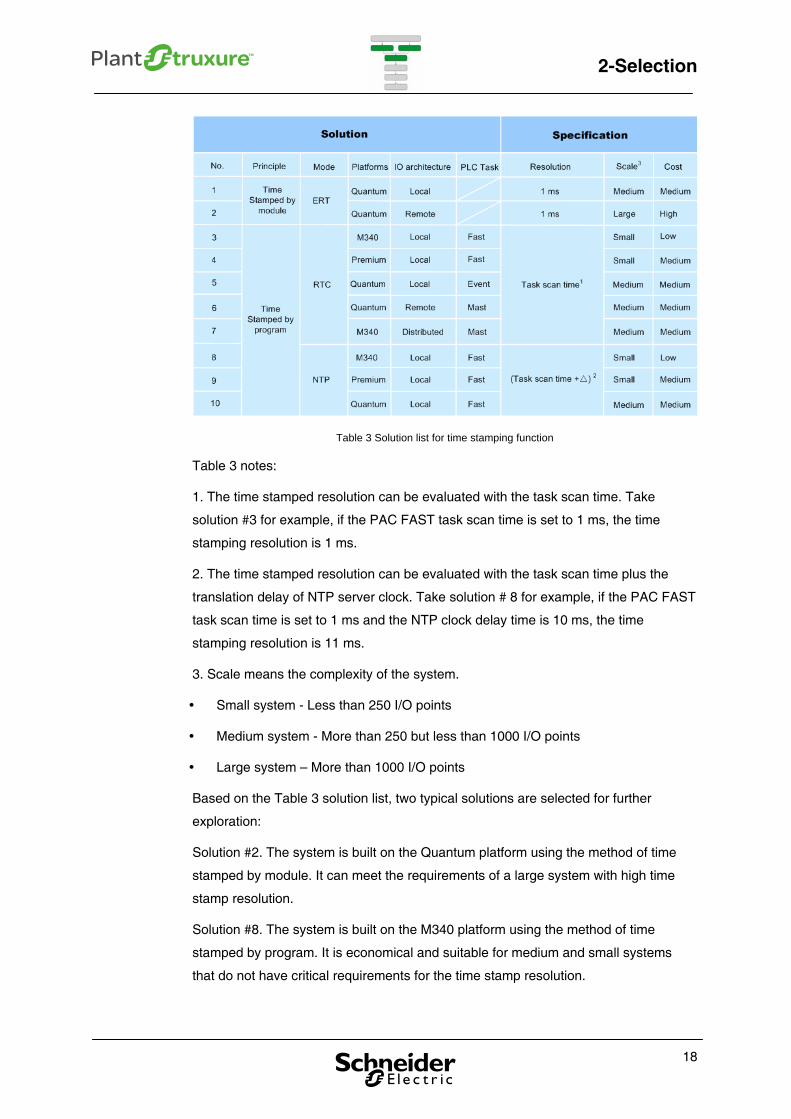
Table 3 Solution list for time stamping function
Table 3 notes:
1. The time stamped resolution can be evaluated with the task scan time. Take
solution #3 for example, if the PAC FAST task scan time is set to 1 ms, the time
stamping resolution is 1 ms.
2. The time stamped resolution can be evaluated with the task scan time plus the
translation delay of NTP server clock. Take solution # 8 for example, if the PAC FAST
task scan time is set to 1 ms and the NTP clock delay time is 10 ms, the time
stamping resolution is 11 ms.
3. Scale means the complexity of the system.
Small system - Less than 250 I/O points
Medium system - More than 250 but less than 1000 I/O points
Large system – More than 1000 I/O points
Based on the Table 3 solution list, two typical solutions are selected for further
exploration:
Solution #2. The system is built on the Quantum platform using the method of time
stamped by module. It can meet the requirements of a large system with high time
stamp resolution.
Solution #8. The system is built on the M340 platform using the method of time
stamped by program. It is economical and suitable for medium and small systems
that do not have critical requirements for the time stamp resolution.
18
2-Selection
19
These two solutions are the ones used in the Design, Configuration, Implementation,
and Operation chapters.

3-Design
20
3-Design
3. Design
This chapter presents system hardware, system software, DFBs, and SCADA design
that can help the user build a time stamping application.
3.1. System hardware design
There are two kinds of time stamping hardware designs, depending on whether the
user chooses the time stamped by module method or the time stamped by program
method.
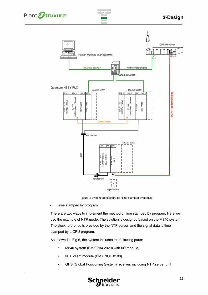
Time stamped by module
This solution is designed for a Quantum system to implement the function of time
stamping by ERT module. The clock reference is in DCF77 format, provided by a
GPS receiver. The signal data is automatically time stamped by the ERT.. A 1 ms
time stamp resolution can be obtained in this application.
As shown in Figure 5, the system includes the following parts:
Modicon Quantum Hot Standby system (140 CPU 671 60) with remote I/O
module
Time stamping module (140 ERT 854 10)
NTP client module (140 NOE 771 11)
GPS (Global Positioning System) receiver, including NTP server unit and
DCF77 unit
Note: NTP server unit provides a clock reference to synchronize the PC time with the
PAC system time.
21
3-Design
Figure 4 System architecture for “time stamped by module”
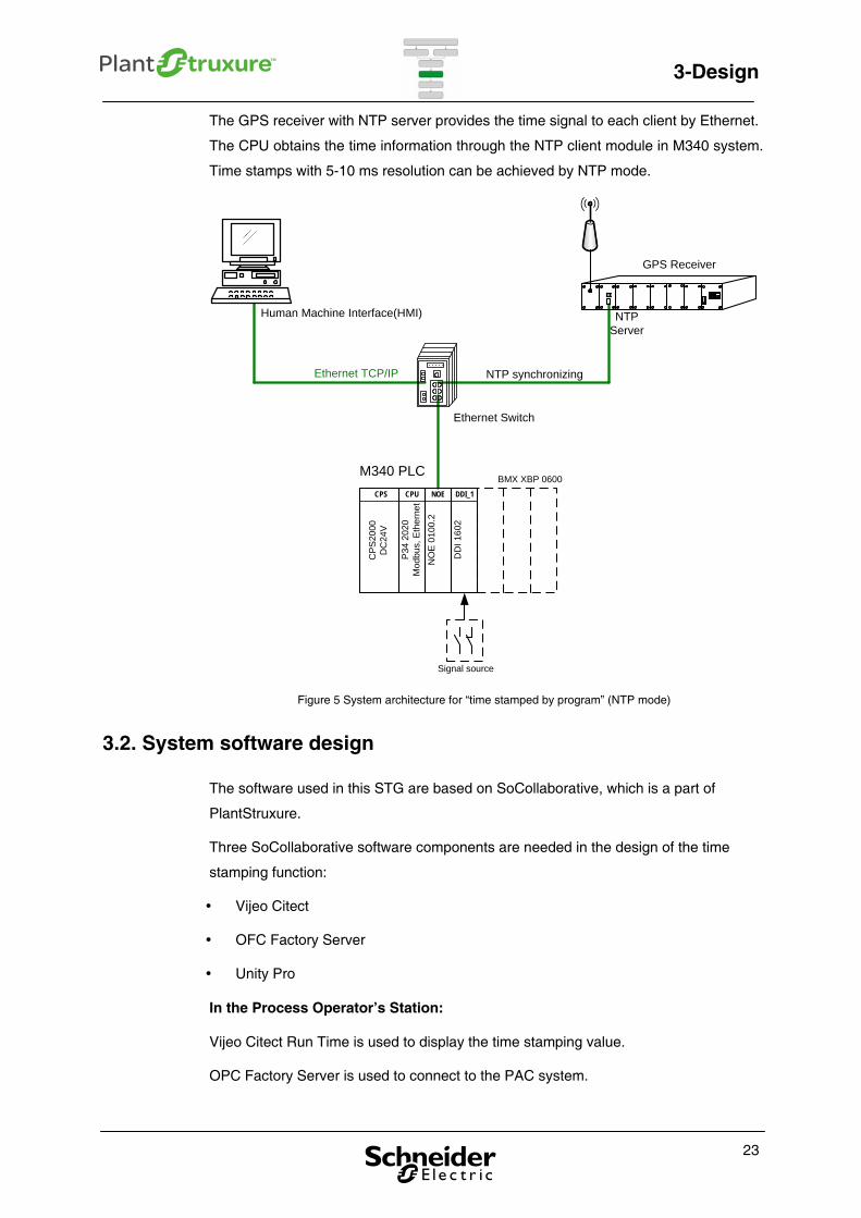
Time stamped by program
There are two ways to implement the method of time stamped by program. Here we
use the example of NTP mode. The solution is designed based on the M340 system.
The clock reference is provided by the NTP server, and the signal data is time
stamped by a CPU program.
As showed in Fig 6, the system includes the following parts:
M340 system (BMX P34 2020) with I/O module,
NTP client module (BMX NOE 0100)
GPS (Global Positioning System) receiver, including NTP server unit
22
3-Design
The GPS receiver with NTP server provides the time signal to each client by Ethernet.
The CPU obtains the time information through the NTP client module in M340 system.
Time stamps with 5-10 ms resolution can be achieved by NTP mode.
BMX XBP 0600M340 PLC
Ethernet Switch
Human Machine Interface(HMI)
GPS Receiver
Ethernet TCP/IP
NTP Server
CPS
CPS
2000
DC
24V
CPU
P34
2020
Mod
bus,
Eth
erne
t
NOE
NO
E 01
00.2
DDI_1
DD
I 160
2
Signal source
NTP synchronizing
Figure 5 System architecture for “time stamped by program” (NTP mode)
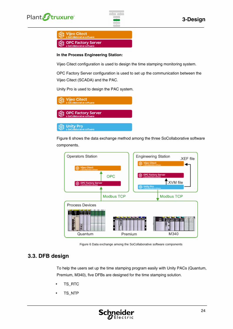
3.2. System software design
The software used in this STG are based on SoCollaborative, which is a part of
PlantStruxure.
Three SoCollaborative software components are needed in the design of the time
stamping function:
Vijeo Citect
OFC Factory Server
Unity Pro
In the Process Operator’s Station:
Vijeo Citect Run Time is used to display the time stamping value.
OPC Factory Server is used to connect to the PAC system.
23
3-Design
In the Process Engineering Station:
Vijeo Citect configuration is used to design the time stamping monitoring system.
OPC Factory Server configuration is used to set up the communication between the
Vijeo Citect (SCADA) and the PAC.
Unity Pro is used to design the PAC system.
Figure 6 shows the data exchange method among the three SoCollaborative software
components.
Figure 6 Data exchange among the SoCollaborative software components
3.3. DFB design
To help the users set up the time stamping program easily with Unity PACs (Quantum,
Premium, M340), five DFBs are designed for the time stamping solution.
TS_RTC
TS_NTP
24
3-Design
TS_ERT
TS_DataBase
TS_DataBase_To_VJC
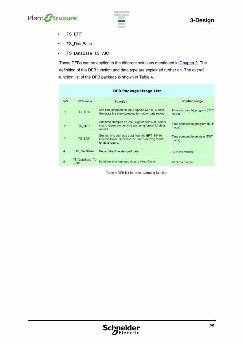
These DFBs can be applied to the different solutions mentioned in Chapter 2. The
definition of the DFB function and data type are explained further on. The overall
function list of the DFB package is shown in Table.4.
Table 4 DFB list for time stamping function
25
3-Design
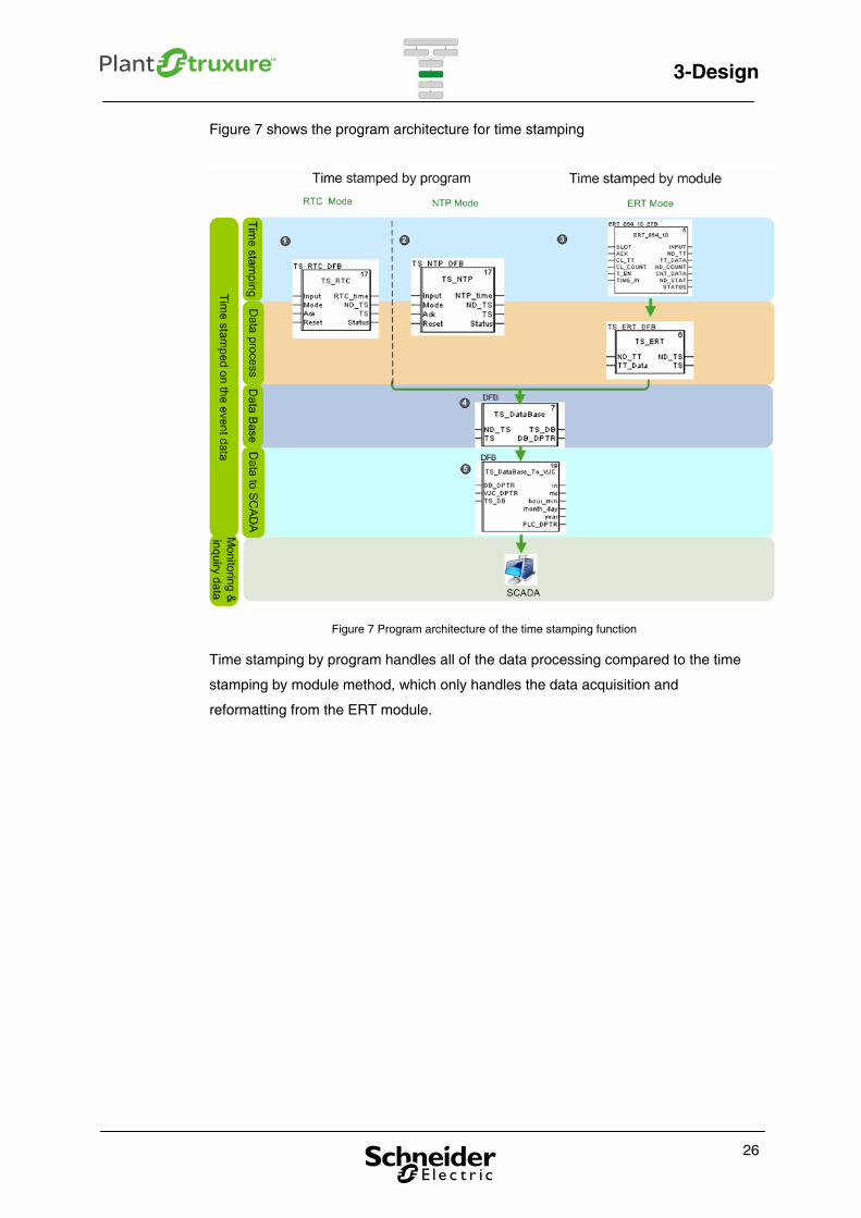
Figure 7 shows the program architecture for time stamping
Figure 7 Program architecture of the time stamping function
Time stamping by program handles all of the data processing compared to the time
stamping by module method, which only handles the data acquisition and
reformatting from the ERT module.
26
3-Design
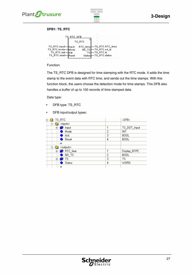
DFB1: TS_RTC
Function:
The TS_RTC DFB is designed for time stamping with the RTC mode. It adds the time
stamp to the event data with RTC time, and sends out the time stamps. With this
function block, the users choose the detection mode for time stamps. This DFB also
handles a buffer of up to 100 records of time stamped data.
Data type:
DFB type: TS_RTC
DFB input/output types:
27
3-Design
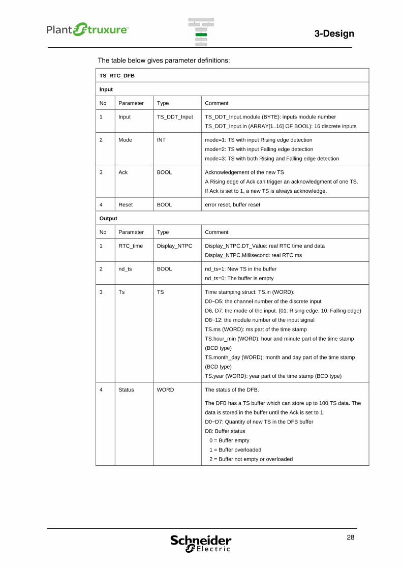
The table below gives parameter definitions:
TS_RTC_DFB
Input
No Parameter Type Comment
1 Input TS_DDT_Input TS_DDT_Input.module (BYTE): inputs module number
TS_DDT_Input.in (ARRAY[1..16] OF BOOL): 16 discrete inputs
2 Mode INT mode=1: TS with input Rising edge detection
mode=2: TS with input Falling edge detection
mode=3: TS with both Rising and Falling edge detection
3 Ack BOOL Acknowledgement of the new TS
A Rising edge of Ack can trigger an acknowledgment of one TS.
If Ack is set to 1, a new TS is always acknowledge.
4 Reset BOOL error reset, buffer reset
Output
No Parameter Type Comment
1 RTC_time Display_NTPC Display_NTPC.DT_Value: real RTC time and data
Display_NTPC.Millisecond: real RTC ms
2 nd_ts BOOL nd_ts=1: New TS in the buffer
nd_ts=0: The buffer is empty
3 Ts TS Time stamping struct: TS.in (WORD):
D0~D5: the channel number of the discrete input
D6, D7: the mode of the input. (01: Rising edge, 10: Falling edge)
D8~12: the module number of the input signal
TS.ms (WORD): ms part of the time stamp
TS.hour_min (WORD): hour and minute part of the time stamp
(BCD type)
TS.month_day (WORD): month and day part of the time stamp
(BCD type)
TS.year (WORD): year part of the time stamp (BCD type)
4 Status WORD The status of the DFB.
The DFB has a TS buffer which can store up to 100 TS data. The
data is stored in the buffer until the Ack is set to 1.
D0~D7: Quantity of new TS in the DFB buffer
D8: Buffer status
0 = Buffer empty
1 = Buffer overloaded
2 = Buffer not empty or overloaded
28
3-Design
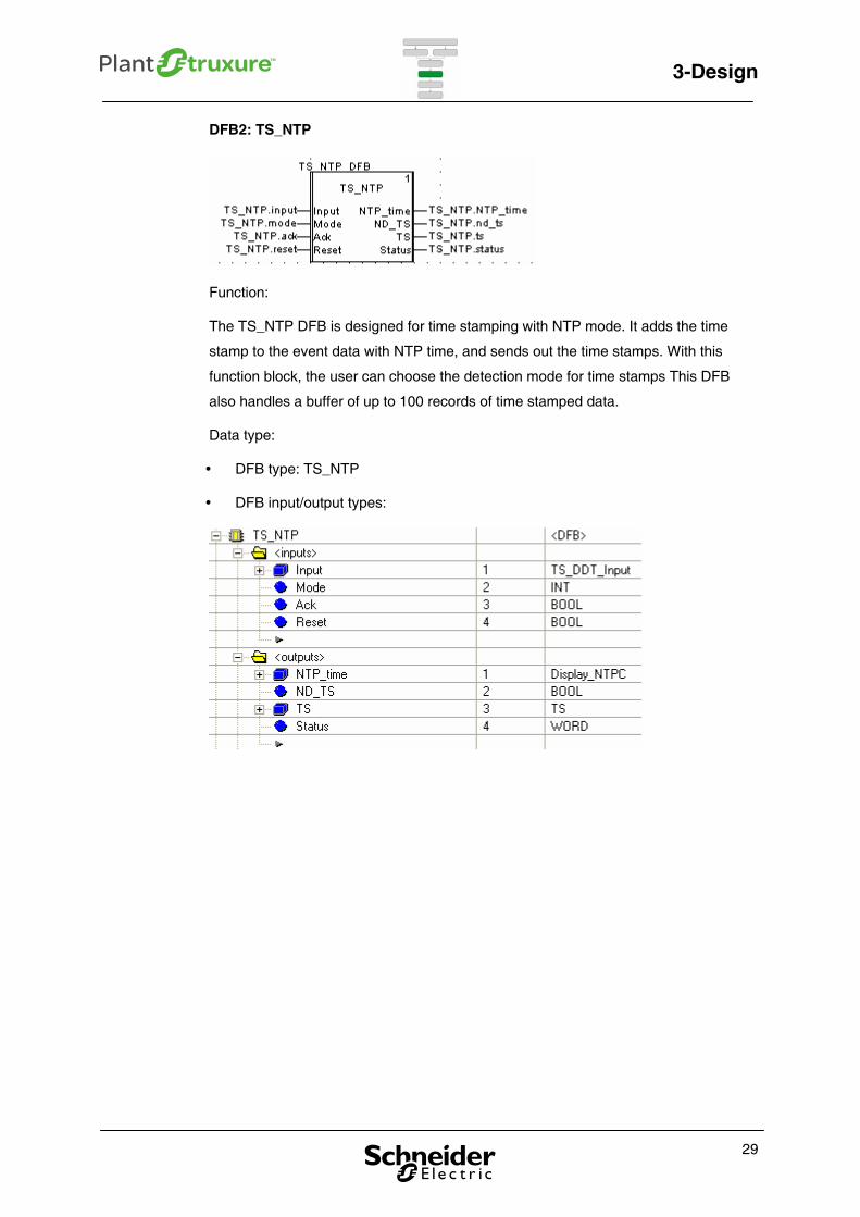
DFB2: TS_NTP
Function:
The TS_NTP DFB is designed for time stamping with NTP mode. It adds the time
stamp to the event data with NTP time, and sends out the time stamps. With this
function block, the user can choose the detection mode for time stamps This DFB
also handles a buffer of up to 100 records of time stamped data.
Data type:
DFB type: TS_NTP
DFB input/output types:
29

3-Design
The next table gives parameter definitions:
TS_NTP_DFB
Input
No Parameter Type Comment
1 Input TS_DDT_Input TS_DDT_Input.module (BYTE): inputs module number
TS_DDT_Input.in (ARRAY[1..16] OF BOOL): 16 discrete inputs
2 Mode INT mode=1: TS with input Rising edge detection
mode=2: TS with input Falling edge detection
mode=3: TS with both Rising and Falling edge detection
3 Ack BOOL Acknowledgement of the new TS
A Rising edge of Ack can trigger an acknowledgment of one TS.
If Ack is set to 1, a new TS is always acknowledge.
4 Reset BOOL error reset, buffer reset
Output
No Parameter Type Comment
1 NTP_time Display_NTPC Display_NTPC.DT_Value: real RTC time and data
Display_NTPC.Millisecond: real RTC ms
2 nd_ts BOOL nd_ts=1: New TS in the buffer
nd_ts=0: The buffer is empty
3 Ts TS Time stamping struct: TS.in (WORD):
D0~D5: the channel number of the discrete input
D6, D7: the mode of the input. (01: Rising edge, 10: Falling edge.)
D8~12: the module number of the input signal.
TS.ms (WORD): ms part of the time stamp
TS.hour_min (WORD): hour and minute part of the time stamp
(BCD type)
TS.month_day (WORD): month and day part of the time stamp
(BCD type)
TS.year (WORD): year part of the time stamp. (BCD type)
4 Status WORD The status of the DFB.
The DFB has a TS buffer which can store up to 100 TS data. The
data is stored in the buffer until the Ack is set to 1.
D0~D7: Quantity of new TS in the DFB buffer
D8: Buffer status
0 = Buffer empty
1 = Buffer overloaded
2 = Buffer not empty nor overloaded
30

3-Design
DFB3: TS_ERT
Function:
The TS_ERT DFB is designed for reformatting ERT mode time stamps. It receives
the time stamps and transforms the data to a format that can be received by SCADA.
This DFB also handles a buffer that can store up to100 records of time stamped data.
Data type:
DFB type: TS_ERT
DFB input/output types:
31
3-Design
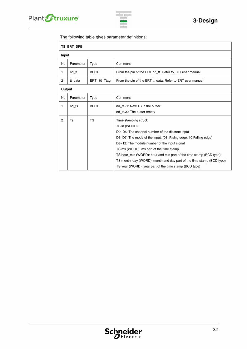
The following table gives parameter definitions:
TS_ERT_DFB
Input
No Parameter Type Comment
1 nd_tt BOOL From the pin of the ERT nd_tt. Refer to ERT user manual
2 tt_data ERT_10_Ttag From the pin of the ERT tt_data. Refer to ERT user manual
Output
No Parameter Type Comment
1 nd_ts BOOL nd_ts=1: New TS in the buffer
nd_ts=0: The buffer empty
2 Ts TS Time stamping struct:
TS.in (WORD):
D0~D5: The channel number of the discrete input
D6, D7: The mode of the input. (01: Rising edge, 10:Falling edge)
D8~12: The module number of the input signal
TS.ms (WORD): ms part of the time stamp
TS.hour_min (WORD): hour and min part of the time stamp (BCD type)
TS.month_day (WORD): month and day part of the time stamp (BCD type)
TS.year (WORD): year part of the time stamp (BCD type)
32
3-Design
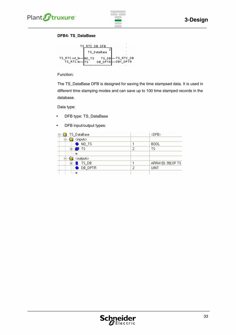
DFB4: TS_DataBase
Function:
The TS_DataBase DFB is designed for saving the time stampsed data. It is used in
different time stamping modes and can save up to 100 time stamped records in the
database.
Data type:
DFB type: TS_DataBase
DFB input/output types:
33
3-Design
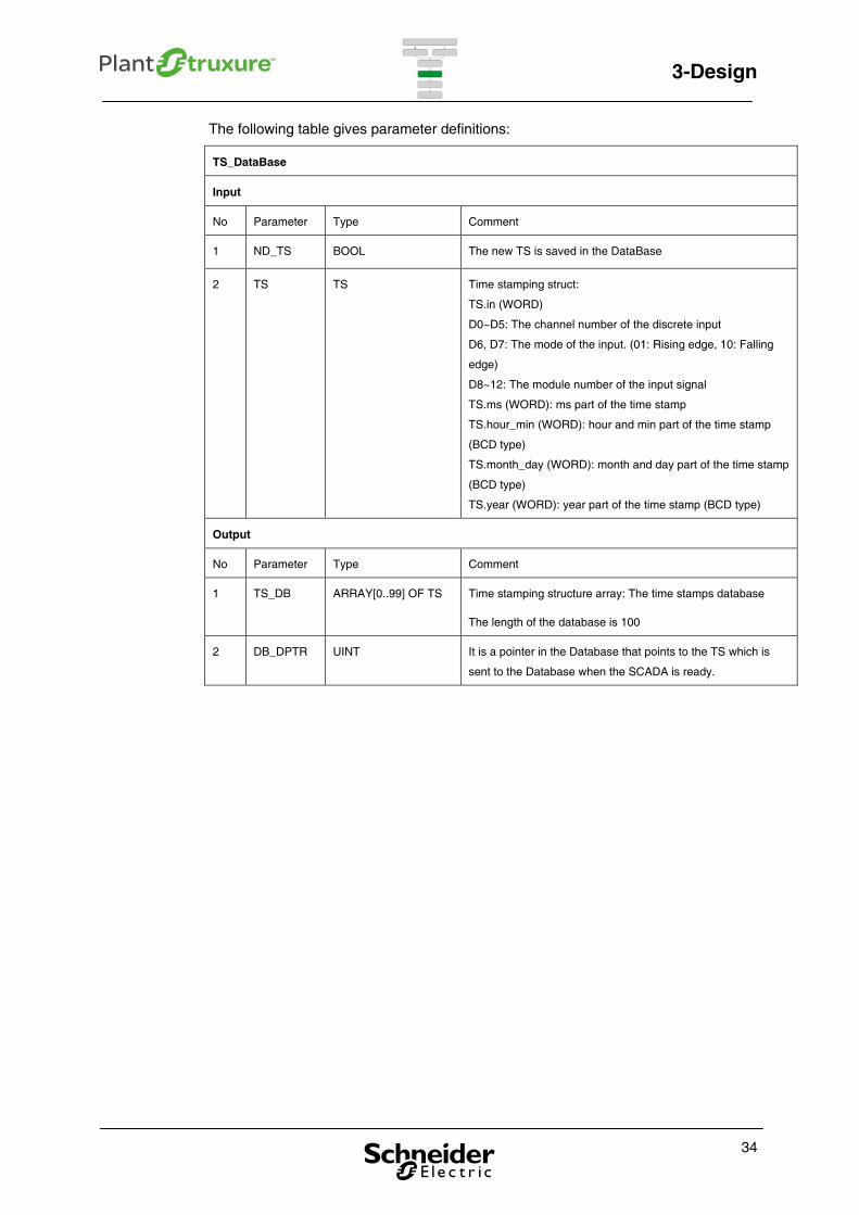
The following table gives parameter definitions:
TS_DataBase
Input
No Parameter Type Comment
1 ND_TS BOOL The new TS is saved in the DataBase
2 TS TS Time stamping struct:
TS.in (WORD)
D0~D5: The channel number of the discrete input
D6, D7: The mode of the input. (01: Rising edge, 10: Falling
edge)
D8~12: The module number of the input signal
TS.ms (WORD): ms part of the time stamp
TS.hour_min (WORD): hour and min part of the time stamp
(BCD type)
TS.month_day (WORD): month and day part of the time stamp
(BCD type)
TS.year (WORD): year part of the time stamp (BCD type)
Output
No Parameter Type Comment
1 TS_DB ARRAY[0..99] OF TS Time stamping structure array: The time stamps database
The length of the database is 100
2 DB_DPTR UINT It is a pointer in the Database that points to the TS which is
sent to the Database when the SCADA is ready.
34
3-Design
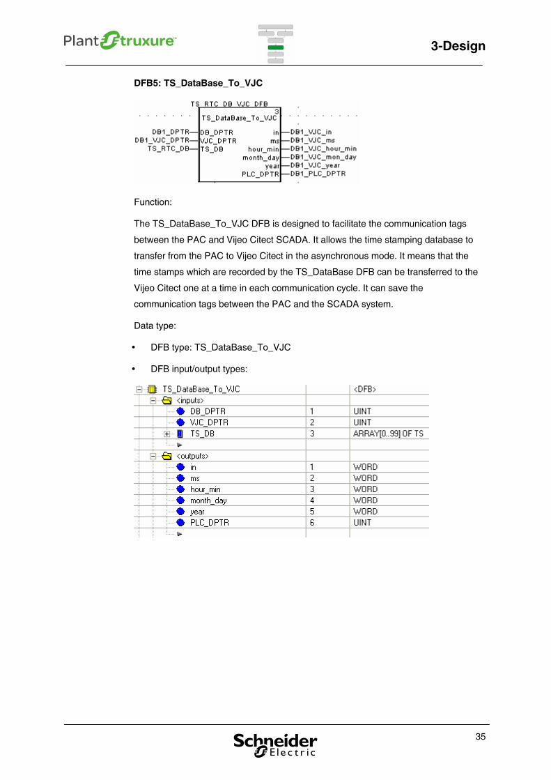
DFB5: TS_DataBase_To_VJC
Function:
The TS_DataBase_To_VJC DFB is designed to facilitate the communication tags
between the PAC and Vijeo Citect SCADA. It allows the time stamping database to
transfer from the PAC to Vijeo Citect in the asynchronous mode. It means that the
time stamps which are recorded by the TS_DataBase DFB can be transferred to the
Vijeo Citect one at a time in each communication cycle. It can save the
communication tags between the PAC and the SCADA system.
Data type:
DFB type: TS_DataBase_To_VJC
DFB input/output types:
35
3-Design
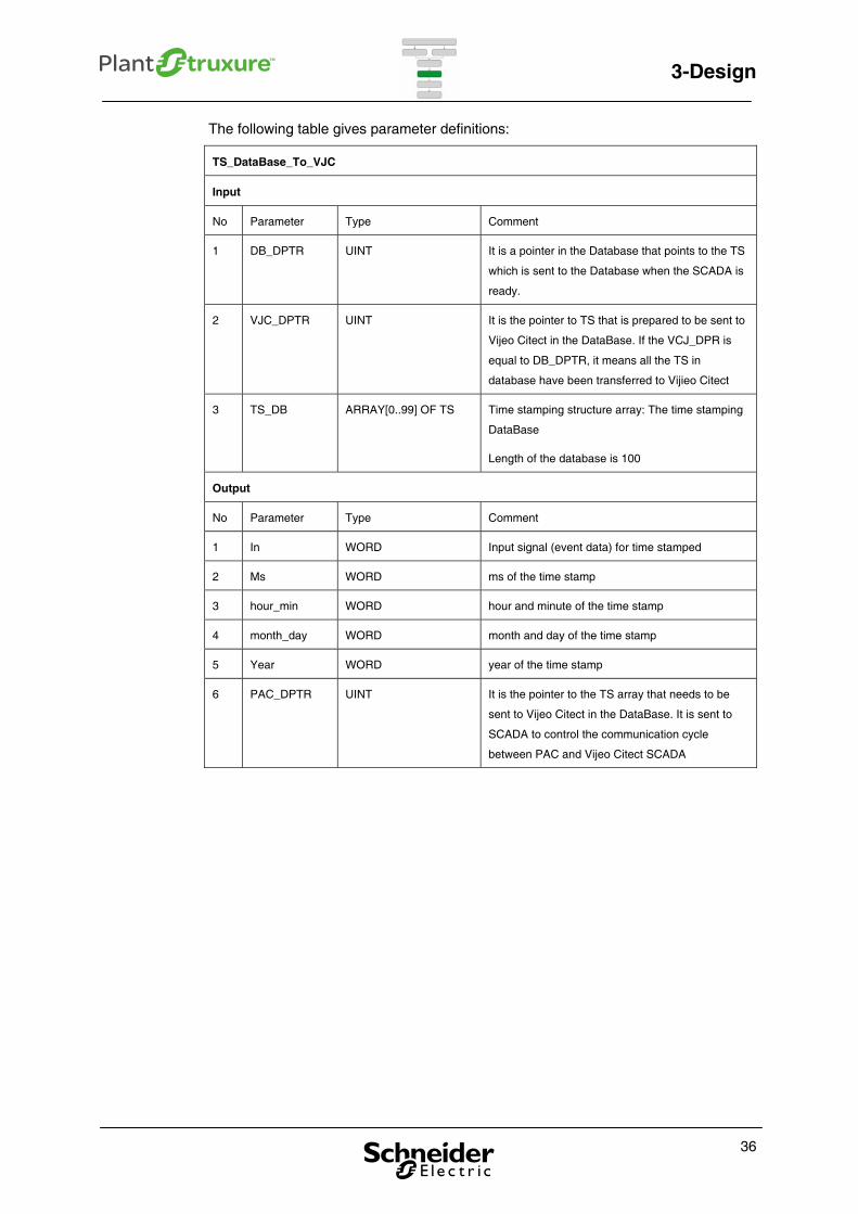
The following table gives parameter definitions:
TS_DataBase_To_VJC
Input
No Parameter Type Comment
1 DB_DPTR UINT It is a pointer in the Database that points to the TS
which is sent to the Database when the SCADA is
ready.
2 VJC_DPTR UINT It is the pointer to TS that is prepared to be sent to
Vijeo Citect in the DataBase. If the VCJ_DPR is
equal to DB_DPTR, it means all the TS in
database have been transferred to Vijieo Citect
3 TS_DB ARRAY[0..99] OF TS Time stamping structure array: The time stamping
DataBase
Length of the database is 100
Output
No Parameter Type Comment
1 In WORD Input signal (event data) for time stamped
2 Ms WORD ms of the time stamp
3 hour_min WORD hour and minute of the time stamp
4 month_day WORD month and day of the time stamp
5 Year WORD year of the time stamp
6 PAC_DPTR UINT It is the pointer to the TS array that needs to be
sent to Vijeo Citect in the DataBase. It is sent to
SCADA to control the communication cycle
between PAC and Vijeo Citect SCADA
36
3-Design
37
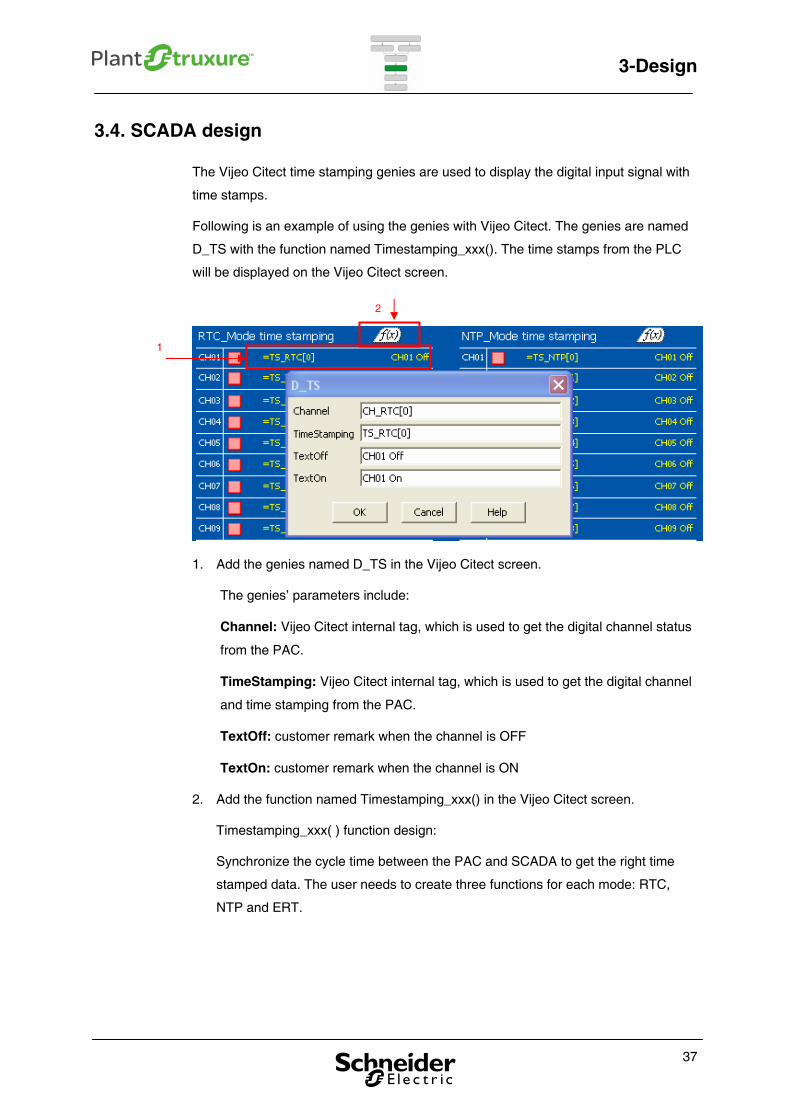
3.4. SCADA design
The Vijeo Citect time stamping genies are used to display the digital input signal with
time stamps.
Following is an example of using the genies with Vijeo Citect. The genies are named
D_TS with the function named Timestamping_xxx(). The time stamps from the PLC
will be displayed on the Vijeo Citect screen.
1. Add the genies named D_TS in the Vijeo Citect screen.
The genies’ parameters include:
Channel: Vijeo Citect internal tag, which is used to get the digital channel status
from the PAC.
TimeStamping: Vijeo Citect internal tag, which is used to get the digital channel
and time stamping from the PAC.
TextOff: customer remark when the channel is OFF
TextOn: customer remark when the channel is ON
2. Add the function named Timestamping_xxx() in the Vijeo Citect screen.
Timestamping_xxx( ) function design:
Synchronize the cycle time between the PAC and SCADA to get the right time
stamped data. The user needs to create three functions for each mode: RTC,
NTP and ERT.
1
2

3-Design
For example, the TimeStamping_RTC( ) function code is presented below:
38

3-Design
39
This figure shows the time stamping genies in the RUN mode.
Channel status Channel status Text

3-Design
40

4-Configuration
4. Configuration
This chapter provides configuration methods according to the different time stamped
solutions.
4.1. Time stamped by module
There are three parts to configure the time stamped by module solution: the time
reference device, PAC and SCADA. This configuration is implemented according to
solution #2, refer to Table 3.
Time reference device - set up GPS receiver
Step Action
1 Put the GPS receiver module into the BBS-3 GPS, and connect the
antenna.
2 Check if the synchronization is OK.
3 Set up the time synchronization module (DCF module).
4 Put the DCF77 module into the BBS-3 GPS and connect it to the ERT
module for time synchronization.
41
4-Configuration
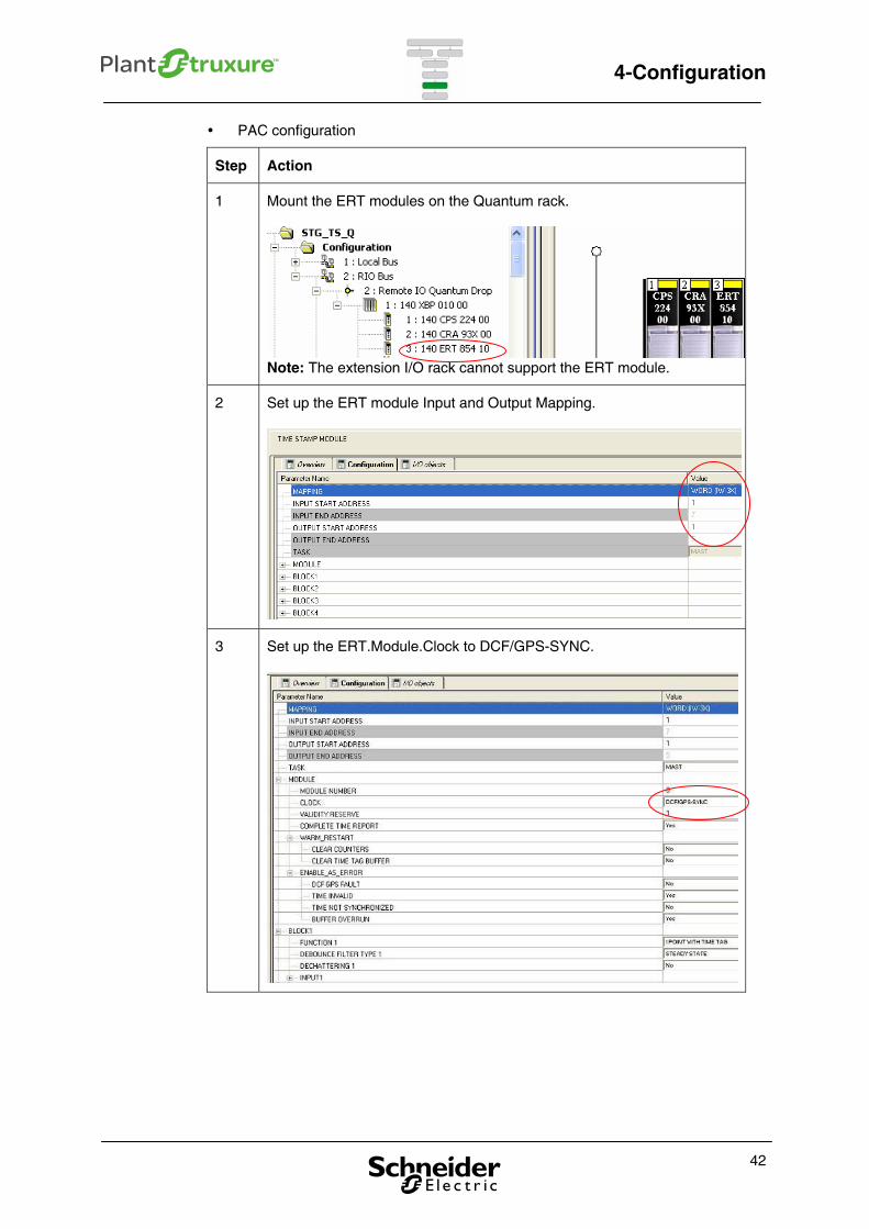
PAC configuration
Step Action
1 Mount the ERT modules on the Quantum rack.
Note: The extension I/O rack cannot support the ERT module.
2 Set up the ERT module Input and Output Mapping.
3 Set up the ERT.Module.Clock to DCF/GPS-SYNC.
42
4-Configuration
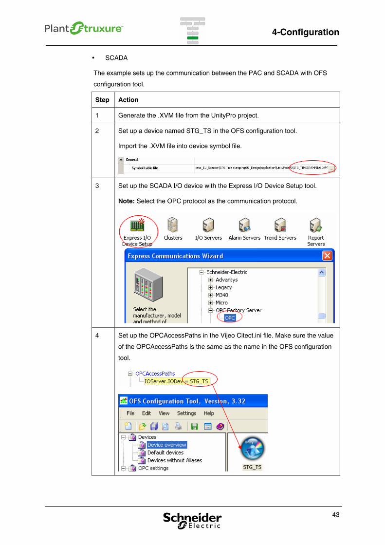
SCADA
The example sets up the communication between the PAC and SCADA with OFS
configuration tool.
Step Action
1 Generate the .XVM file from the UnityPro project.
2 Set up a device named STG_TS in the OFS configuration tool.
Import the .XVM file into device symbol file.
3 Set up the SCADA I/O device with the Express I/O Device Setup tool.
Note: Select the OPC protocol as the communication protocol.
4 Set up the OPCAccessPaths in the Vijeo Citect.ini file. Make sure the value
of the OPCAccessPaths is the same as the name in the OFS configuration
tool.
43
4-Configuration
4.2. Time stamped by program
There are three parts to configure for the time stamped by program method; the time
reference device, PAC and SCADA. The example is implemented according to
solution #3, refer to Table 3.
Time reference device
There are two parts to the time reference configuration, the GPS receiver setup and
the time synchronization setup.
Set up GPS receiver:
Step Action
1 Put the GPS receiver module into the BBS-3 GPS and connect antenna.
2 Check if the synchronization is correct.
Set up time synchronization module (NTP server):
Step Action
1 Put the NTP server module into the BBS-3 GPS and connect it to the
network for network time synchronization.
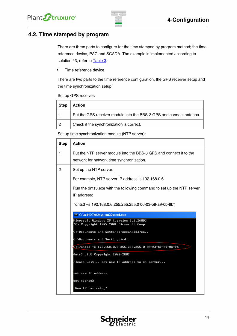
2 Set up the NTP server.
For example, NTP server IP address is 192.168.0.6
Run the dnts3.exe with the following command to set up the NTP server
IP address:
“dnts3 –s 192.168.0.6 255.255.255.0 00-03-b9-a9-0b-9b”
44
4-Configuration
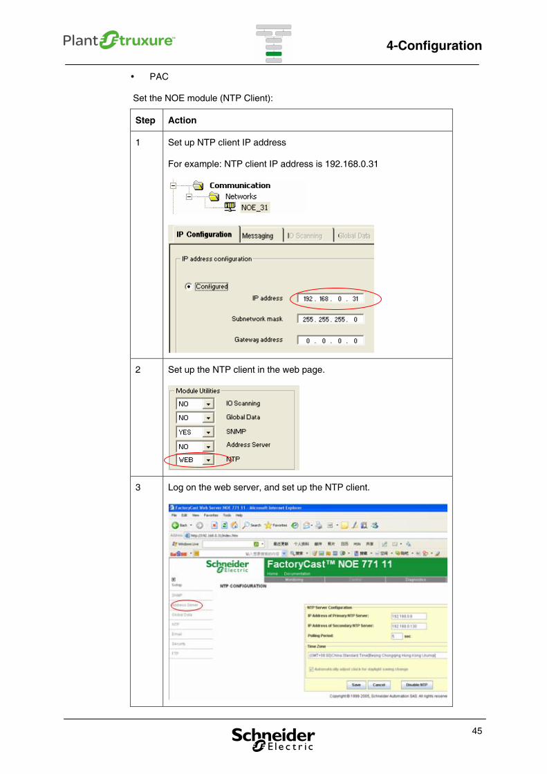
PAC
Set the NOE module (NTP Client):
Step Action
1 Set up NTP client IP address
For example: NTP client IP address is 192.168.0.31
2 Set up the NTP client in the web page.
3 Log on the web server, and set up the NTP client.
45
4-Configuration
46
SCADA
This process is same as the one described in Chapter 4.1.
5-Implementation
5. Implementation
This chapter helps user to implement the time stamping application with three
different time stamping modes. It includes PAC programming and SCADA
programming.
5.1. PAC
There are two steps in the PAC programming: time stamping and sending time
stamps to SCADA.
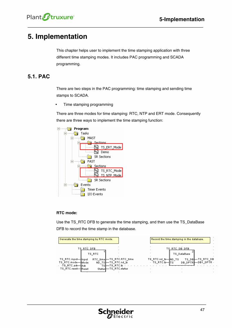
Time stamping programming
There are three modes for time stamping: RTC, NTP and ERT mode. Consequently
there are three ways to implement the time stamping function:
RTC mode:
Use the TS_RTC DFB to generate the time stamping, and then use the TS_DataBase
DFB to record the time stamp in the database.
47
5-Implementation
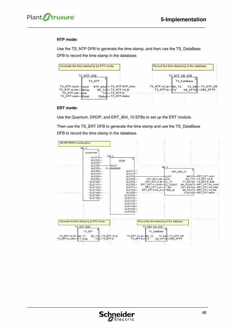
NTP mode:
Use the TS_NTP DFB to generate the time stamp, and then use the TS_DataBase
DFB to record the time stamp in the database.
ERT mode:
Use the Quantum, DROP, and ERT_854_10 EFBs to set up the ERT module.
Then use the TS_ERT DFB to generate the time stamp and use the TS_DataBase
DFB to record the time stamp in the database.
48
5-Implementation
49
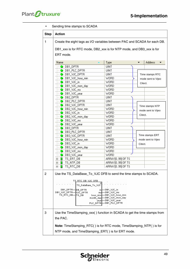
Sending time stamps to SCADA
Step Action
1 Create the eight tags as I/O variables between PAC and SCADA for each DB.
DB1_xxx is for RTC mode, DB2_xxx is for NTP mode, and DB3_xxx is for
ERT mode.
2 Use the TS_DataBase_To_VJC DFB to send the time stamps to SCADA.
3 Use the TimeStamping_xxx( ) function in SCADA to get the time stamps from
the PAC.
Note: TimeStamping_RTC( ) is for RTC mode, TimeStamping_NTP( ) is for
NTP mode, and TimeStamping_ERT( ) is for ERT mode.
Time stamps RTC
mode sent to Vijeo
Citect.
Time stamps NTP
mode sent to Vijeo
Citect.
Time stamps ERT
mode sent to Vijeo
Citect.
5-Implementation
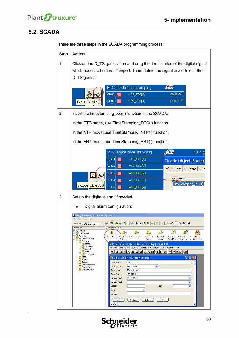
5.2. SCADA
There are three steps in the SCADA programming process:
Step Action
1 Click on the D_TS genies icon and drag it to the location of the digital signal
which needs to be time stamped. Then, define the signal on/off text in the
D_TS genies.
2 Insert the timestamping_xxx( ) function in the SCADA:
In the RTC mode, use TimeStamping_RTC( ) function.
In the NTP mode, use TimeStamping_NTP( ) function.
In the ERT mode, use TimeStamping_ERT( ) function.
3 Set up the digital alarm, if needed.
Digital alarm configuration:
50
5-Implementation
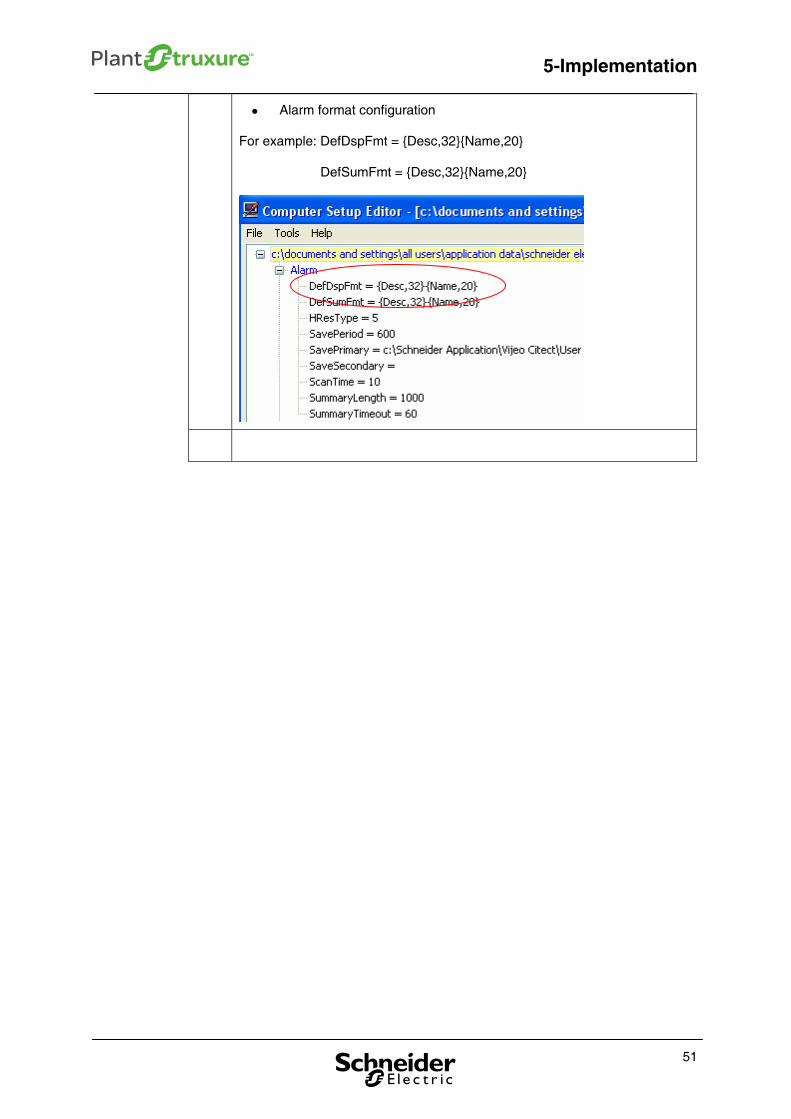
Alarm format configuration
For example: DefDspFmt = {Desc,32}{Name,20}
DefSumFmt = {Desc,32}{Name,20}
51
5-Implementation
52
6-Operation
6. Operation
This chapter presents the results of the time stamping, which includes time stamping
diagnostics and alarms.
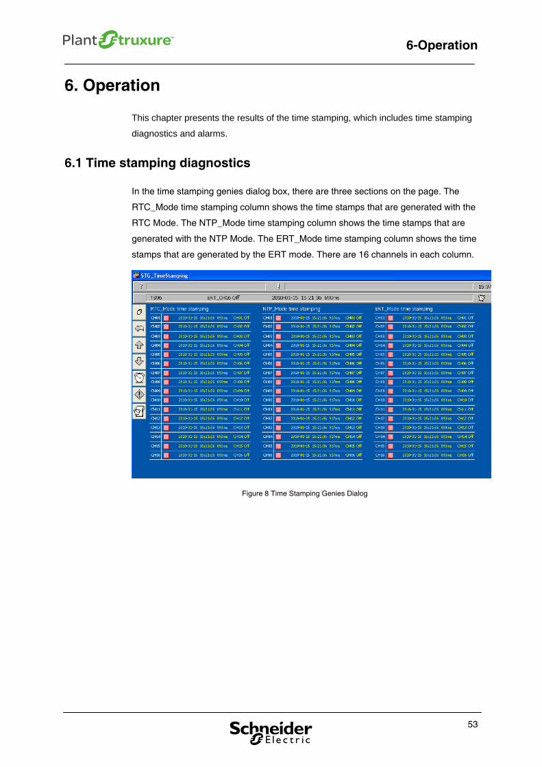
6.1 Time stamping diagnostics
In the time stamping genies dialog box, there are three sections on the page. The
RTC_Mode time stamping column shows the time stamps that are generated with the
RTC Mode. The NTP_Mode time stamping column shows the time stamps that are
generated with the NTP Mode. The ERT_Mode time stamping column shows the time
stamps that are generated by the ERT mode. There are 16 channels in each column.
Figure 8 Time Stamping Genies Dialog
53
6-Operation
54
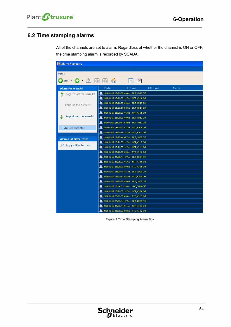
6.2 Time stamping alarms
All of the channels are set to alarm. Regardless of whether the channel is ON or OFF,
the time stamping alarm is recorded by SCADA.
Figure 9 Time Stamping Alarm Box
7- HPP Example
7. Hydro power plant example
The purpose of this chapter is to provide a sample case to guide the user in
implementing time stamping in process automation using the methods discussed in
the previous chapters. Take the hydro power plant application as an example. This
chapter describes the hydro power plant application background, system architecture,
PAC application, SCADA application, User operation and Device list.
7.1. Introduction to the hydro power plant process
This section introduces the hydro power plant process system, which includes the
scale of the plant and the control system used in the hydro power plant process.
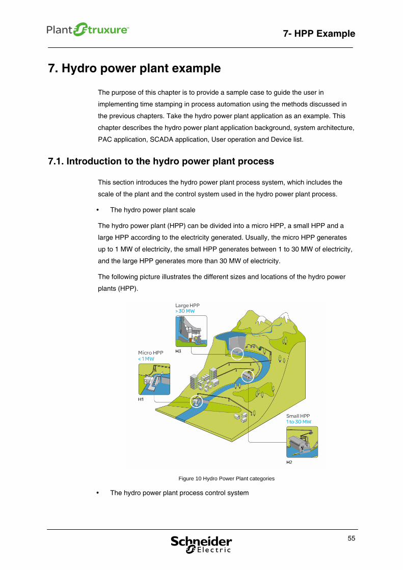
The hydro power plant scale
The hydro power plant (HPP) can be divided into a micro HPP, a small HPP and a
large HPP according to the electricity generated. Usually, the micro HPP generates
up to 1 MW of electricity, the small HPP generates between 1 to 30 MW of electricity,
and the large HPP generates more than 30 MW of electricity.
The following picture illustrates the different sizes and locations of the hydro power
plants (HPP).
Figure 10 Hydro Power Plant categories
The hydro power plant process control system
55
7- HPP Example
The hydro power control system includes the main machinery and an auxiliary
equipment system.
Main machinery system: It is composed of a turbine, generator, speed controller
and exciter system. The turbine transforms the water’s potential energy into
mechanical rotational energy. The turbine drives the generator. The generator
transforms the mechanical energy into electrical energy. A speed controller ensures
the balance between the output of turbine and the load of the generator, and ensures
that the turbine rotates at a certain speed (frequency). The exciter system transforms
the output of generation into DC power by exciting the transformer and the
semiconductor rectifier.
Auxiliary equipment system: This is composed of the water supply, a substation,
the oil supply and a compressed air system.
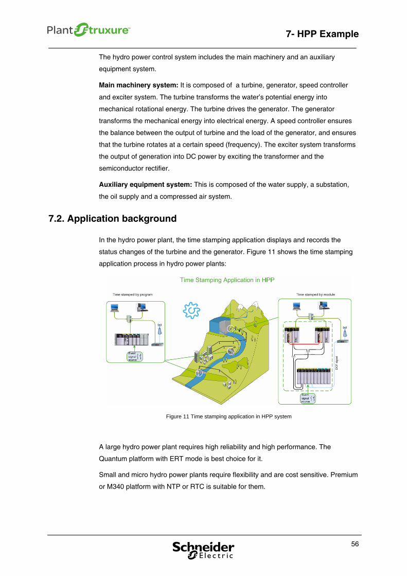
7.2. Application background
In the hydro power plant, the time stamping application displays and records the
status changes of the turbine and the generator. Figure 11 shows the time stamping
application process in hydro power plants:
Figure 11 Time stamping application in HPP system
A large hydro power plant requires high reliability and high performance. The
Quantum platform with ERT mode is best choice for it.
Small and micro hydro power plants require flexibility and are cost sensitive. Premium
or M340 platform with NTP or RTC is suitable for them.
56
7- HPP Example
7.3. System architecture
The following is a detailed diagram of the system architecture of the time stamping
solutions in the hydro power plant. In this STG, two kinds of time stamping solutions
are offered: time stamped by program and time stamped by module.
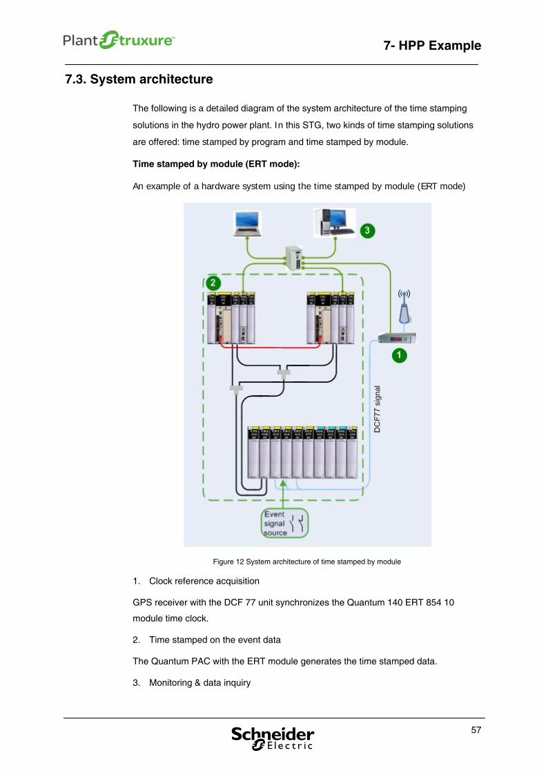
Time stamped by module (ERT mode):
An example of a hardware system using the time stamped by module (ERT mode)
Figure 12 System architecture of time stamped by module
1. Clock reference acquisition
GPS receiver with the DCF 77 unit synchronizes the Quantum 140 ERT 854 10
module time clock.
2. Time stamped on the event data
The Quantum PAC with the ERT module generates the time stamped data.
3. Monitoring & data inquiry
57
7- HPP Example
SCADA can be used to display the different applications with time stamping, such as
SOE or digital alarms.
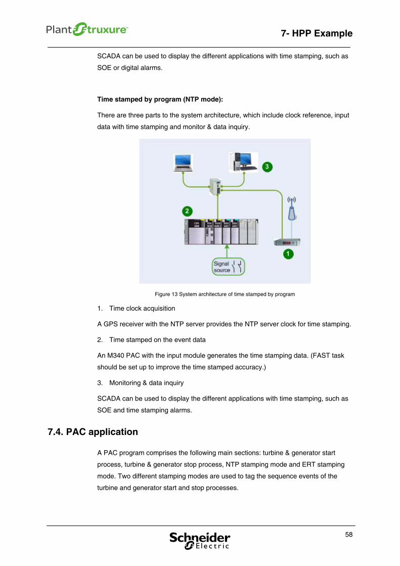
Time stamped by program (NTP mode):
There are three parts to the system architecture, which include clock reference, input
data with time stamping and monitor & data inquiry.
Figure 13 System architecture of time stamped by program
1. Time clock acquisition
A GPS receiver with the NTP server provides the NTP server clock for time stamping.
2. Time stamped on the event data
An M340 PAC with the input module generates the time stamping data. (FAST task
should be set up to improve the time stamped accuracy.)
3. Monitoring & data inquiry
SCADA can be used to display the different applications with time stamping, such as
SOE and time stamping alarms.
7.4. PAC application
A PAC program comprises the following main sections: turbine & generator start
process, turbine & generator stop process, NTP stamping mode and ERT stamping
mode. Two different stamping modes are used to tag the sequence events of the
turbine and generator start and stop processes.
58
7- HPP Example
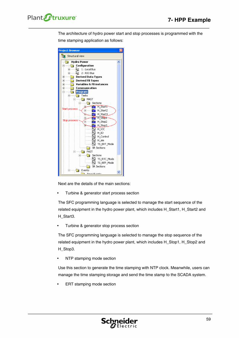
The architecture of hydro power start and stop processes is programmed with the
time stamping application as follows:
Next are the details of the main sections:
Turbine & generator start process section
The SFC programming language is selected to manage the start sequence of the
related equipment in the hydro power plant, which includes H_Start1, H_Start2 and
H_Start3.
Turbine & generator stop process section
The SFC programming language is selected to manage the stop sequence of the
related equipment in the hydro power plant, which includes H_Stop1, H_Stop2 and
H_Stop3.
NTP stamping mode section
Use this section to generate the time stamping with NTP clock. Meanwhile, users can
manage the time stamping storage and send the time stamp to the SCADA system.
ERT stamping mode section
59
7- HPP Example
Use this section to get the time stamping from the ERT module. Meanwhile, users
can manage the time stamping storage and send the time stamp to the SCADA
system.
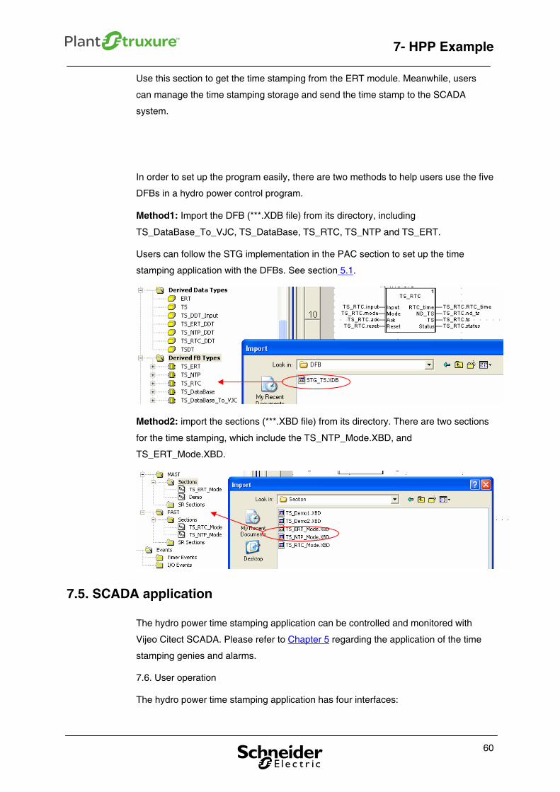
In order to set up the program easily, there are two methods to help users use the five
DFBs in a hydro power control program.
Method1: Import the DFB (***.XDB file) from its directory, including
TS_DataBase_To_VJC, TS_DataBase, TS_RTC, TS_NTP and TS_ERT.
Users can follow the STG implementation in the PAC section to set up the time
stamping application with the DFBs. See section 5.1.
Method2: import the sections (***.XBD file) from its directory. There are two sections
for the time stamping, which include the TS_NTP_Mode.XBD, and
TS_ERT_Mode.XBD.
7.5. SCADA application
The hydro power time stamping application can be controlled and monitored with
Vijeo Citect SCADA. Please refer to Chapter 5 regarding the application of the time
stamping genies and alarms.
7.6. User operation
The hydro power time stamping application has four interfaces:
60
7- HPP Example
Hydro power main control system
Stop status to generation status process
Generation status process to stop status
Time stamping database
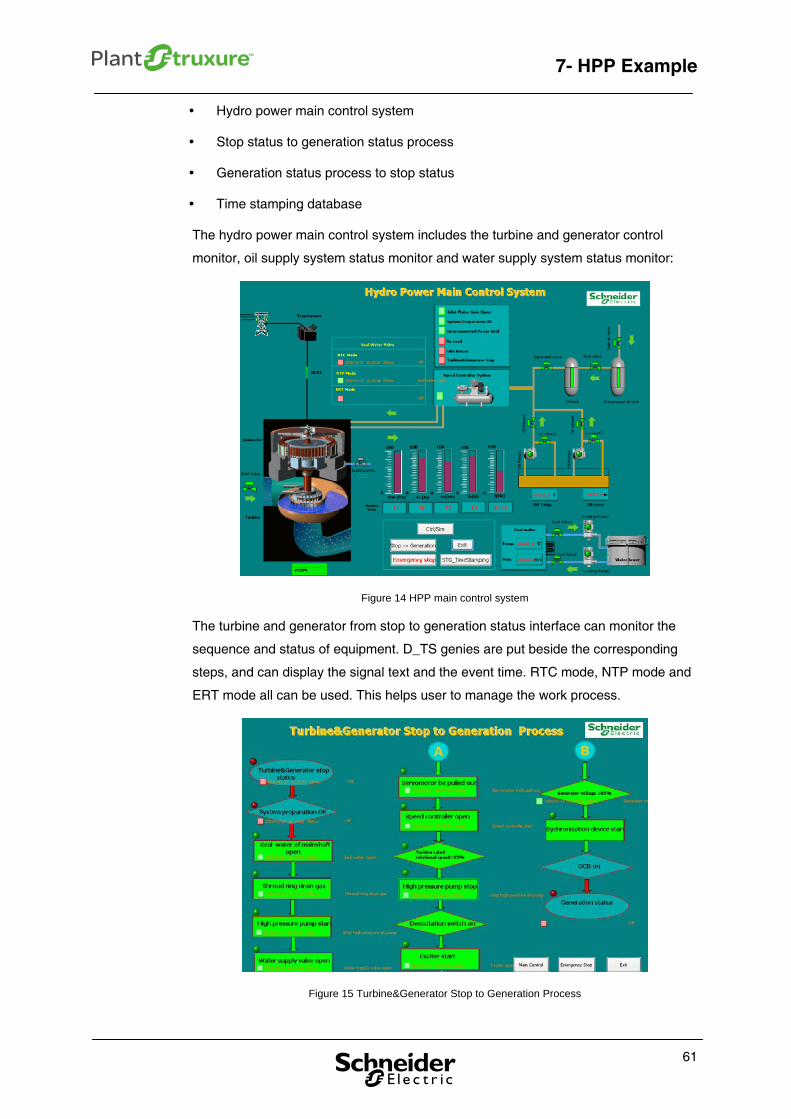
The hydro power main control system includes the turbine and generator control
monitor, oil supply system status monitor and water supply system status monitor:
Figure 14 HPP main control system
The turbine and generator from stop to generation status interface can monitor the
sequence and status of equipment. D_TS genies are put beside the corresponding
steps, and can display the signal text and the event time. RTC mode, NTP mode and
ERT mode all can be used. This helps user to manage the work process.
Figure 15 Turbine&Generator Stop to Generation Process
61

7- HPP Example
The turbine and generator emergency stop process interface can monitor the
sequence and status of equipment. D_TS genies are put beside the corresponding
steps, and can display the signal text and the event time. RTC mode, NTP mode and
ERT modes all can be used. This provides the user with a way to manage the work
process.
Figure 16 Turbine Emergency Stop Process
62
7- HPP Example
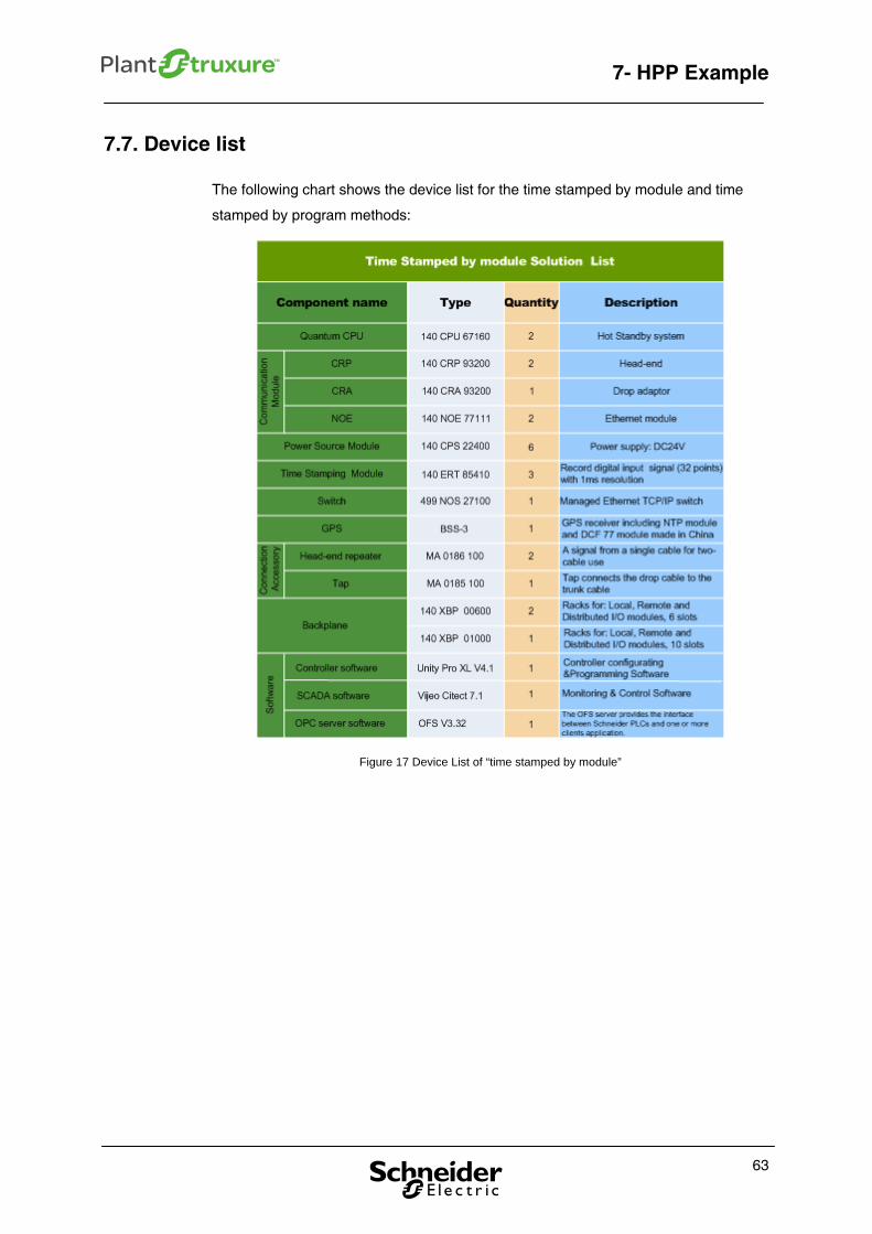
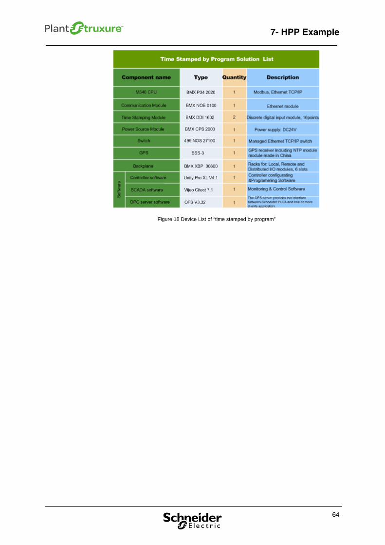
7.7. Device list
The following chart shows the device list for the time stamped by module and time
stamped by program methods:
Figure 17 Device List of “time stamped by module”
63
7- HPP Example
64
Figure 18 Device List of “time stamped by program”
Appendix
Appendix
Abbreviations
CPU – Central Process Unit
DCF77 – Longwave time signal and standard-frequency radio station
DFB – Derived Function Block
ERT – Shortened name for the Quantum 140 ERT 854 10 module
GPS – Global positioning system
I/O – Input and output
NTP – Network Time Protocol
PAC – Programmable Automation Controller
RTC – Real Time Clock
SCADA – Supervisory Control and Data Acquisition
SOE – Sequence of Event
65

Schneider Electric Industries SAS
Head Office
89, bd Franklin Roosvelt
92506 Rueil-Malmaison Cedex
FRANCE
www.schneider-electric.com
Due to evolution of standards and equipment, characteristics indicated in texts and images in this document are binding only after confirmation by our departments Print:
Version 1.6 – MM DDDD