Embed Size (px)
Citation preview

Leonardo
Determining the Preferred Viewpoint in Linear PerspectiveAuthor(s): Richard GreeneSource: Leonardo, Vol. 16, No. 2 (Spring, 1983), pp. 97-102Published by: The MIT PressStable URL: http://www.jstor.org/stable/1574793 .
Accessed: 18/06/2014 17:01
Your use of the JSTOR archive indicates your acceptance of the Terms & Conditions of Use, available at .http://www.jstor.org/page/info/about/policies/terms.jsp
.JSTOR is a not-for-profit service that helps scholars, researchers, and students discover, use, and build upon a wide range ofcontent in a trusted digital archive. We use information technology and tools to increase productivity and facilitate new formsof scholarship. For more information about JSTOR, please contact [email protected].
.
The MIT Press and Leonardo are collaborating with JSTOR to digitize, preserve and extend access toLeonardo.
http://www.jstor.org
This content downloaded from 195.34.78.78 on Wed, 18 Jun 2014 17:01:19 PMAll use subject to JSTOR Terms and Conditions
Leonardo, Vol. 16, No. 2, pp. 97-102, 1983 Printed in Great Britain
0024-094X/83$3.00+0.00 Pergamon Press Ltd.
DETERMINING THE PREFERRED VIEWPOINT IN LINEAR PERSPECTIVE
Richard Greene*
Abstract-The basic theory of linear perspective is reviewed, and it is shown that a perspective picture implies the existence of a unique point in space which is, on optical grounds, the preferred viewpoint of the picture. The concepts of the visible, terrestrial, and sensible horizons are then compared, and it isfound that the horizon in a picture can give the vertical position of the viewpoint. The outside knowledge or assumptions which are necessary in order completely to determine the preferred viewpoint are then considered. The assumptions used here are based on common knowledge of the three-dimensional shapes and orientations of pictured objects and knowledge of the picture-making processes. A step-by-step procedure is then given forfinding the location of the preferred viewpoints of one-, two- and three-point perspectives. It is found that a three-point perspectiveprovides more information about the viewpoint, with fewer assumptions, than either of the other two cases. Finally, the reasons why alternate viewpoints may be just as acceptable as the optically preferred one are discussed.
I.
If one wants to take an unblurred photograph of a stationary subject, one must hold the camera fixed at a single position. Similarly, if one is trying to draw a self-consistent picture of a three-dimensional scene, one must choose (consciously or not) a single point of view. Conventionally this viewpoint is located directly opposite the geometric center of the picture, at a distance of the order of the picture's width. In cases where this convention has not been adhered to or a more precise determination is desired, the procedure to be given below may be used to locate this viewpoint accurately.
We will begin with a brief review of the physical laws which determine how a three-dimensional object may be accurately represented on a flat surface-the laws of linear perspective.
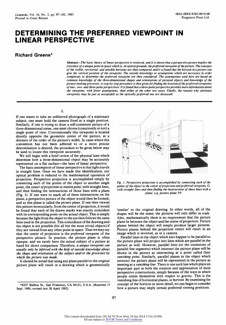
The basic assumption of linear perspective is that light travels in straight lines. Once we have made this identification, our optical problem is reduced to the mathematical operation of projection. Perspective projection is accomplished simply by connecting each of the points of the object to another single point, the center of projection or station point, with straight lines, and then finding the intersections of those lines with a plane (Fig. 1). If one were to mark all of these intersections on the plane, a perspective picture of the object would then be formed, and so this plane is called the picture plane. If one then viewed this picture monocularly, from the center of projection, it would be found that each of the drawn marks was exactly coincident with its corresponding point on the actual object. This is simply because the light from the object to the eye then follows the same lines used in the projection. This coincidence of the drawing and the object is not possible (for all but the most trivial objects) if they are viewed from any other point in space. Thus we may say that the center of projection is the preferred viewpoint of the perspective picture. In practice, the picture plane is often opaque, and we rarely have the actual subject of a picture at hand for direct comparison. Therefore, a unique viewpoint can usually only be inferred with the help of outside knowledge about the shape and orientation of the subject and/or the processes by which the picture was made.
It should be noted that using any plane parallel to the original picture plane will result in a drawing which is geometrically
*4337 Balboa St., San Francisco, CA 94121, U.S.A. (Received 17 Sept. 1980, revised text 20 April 1982)
Fig. 1. Perspective projection is accomplished by connecting each of the points of the object to the center of projection and preferred viewpoint, 0, with straight lines and then finding the intersections of those lines with a
plane, e.g. picture plane PP.
'similar' to the original drawing. In other words, all of the shapes will be the same; the pictures will only differ in scale. Also, mathematically there is no requirement that the picture plane lie between the object and the center of projection. Picture planes behind the object will simply produce larger pictures. Picture planes behind the projection center will result in an image which is inverted, as in a camera.
Parallel lines in the object which also happen to be parallel to the picture plane will project into lines which are parallel in the picture as well. However, parallel lines (or the extensions of parallel line segments) which intersect the picture plane will be shown in the picture as intersecting at a point called their vanishing point. Similarly, parallel planes in the object which intersect the picture plane will be represented in the picture as meeting at a vanishing line. There is one such line which plays an important part in both the creation and appreciation of most perspective constructions, simply because of the ways in which people orient themselves with respect to gravity. This is the vanishing line of horizontal planes, or horizon. By examining the concept of the horizon in more detail, we can begin to consider how a picture may imply certain preferred viewing positions.
97
This content downloaded from 195.34.78.78 on Wed, 18 Jun 2014 17:01:19 PMAll use subject to JSTOR Terms and Conditions
Richard Greene
II.
The word 'horizon' is used in a number of different senses which we must be careful to distinguish. First of all, there is the apparent or visible horizon, the apparent meeting place of the surface of the earth and the sky. This may be as far away as a distant mountain range or literally as near as one's own nose. Secondly, there is the terrestrial horizon, determined by the most distant visible points on the surface of a sphere the size of Earth. This is virtually identical with the visible horizon of a calm sea. Finally, there is the line referred to above, the vanishing line of horizontal planes, called the rational or sensible horizon. This last horizon is the one which would be the visible horizon if one were standing on an infinite horizontal plane. Even though no one has ever actually seen an infinite plane, this sensible horizon forms the basis of most handmade perspectives. In order to see why, it is useful to compare the horizon of an infinite plane with that of a sphere.
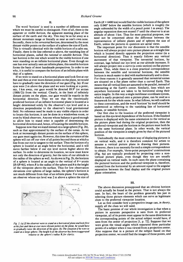
If we were to stand on a horizontal plane and look first at our feet and then at ever more distant points on the plane, we would have to gradually raise the direction of our gaze (Fig. 2a). If our eyes were 2 m above the plane and we were looking at a point, say, 1 km away, our gaze would be directed 89.9? (or arctan (1000/2)) from the vertical. Clearly, in the limit of infinitely distant points on the plane, our gaze would lie exactly in the horizontal direction. Thus we see that the theoretically predicted horizon of an infinite horizontal plane is located at a height determined solely by the observer's eye level and in a direction perpendicular to the observer's local gravitational field. No reference need be made to any visible objects in order to locate this horizon; it can be done in a windowless room, or even by blind observers. Anyone whose balance is good enough to allow him to stand erect is capable of determining the horizontal direction and, hence, of locating the sensible horizon.
Suppose now that we stand instead on a large sphere (Fig. 2b), such as that approximated by the surface of the ocean. As we look at increasingly distant points on the surface of this sphere, our gaze must again rise. However, this time the curvature of the sphere will cut off our view of all points beyond those at which a line from our eye is tangent to the surface. Thus the horizon of a sphere is located at an angle below the horizontal, and it will move farther below if our eye level moves higher above the surface. In order to determine its location, we now must know not only the direction of gravity, but the ratio of our altitude to the radius of the sphere as well. As shown in Fig. 2b, the horizon of a sphere is located at an angle to the vertical of 0 = arcsin [R/(R+h)], where R is the radius of the sphere and h is the height of the viewpoint above the surface. Thus for low observation elevations over spheres of large radius, the sphere's horizon is not much different from that of an infinite plane. For example, an observer whose eye level was 2 m above a sphere the size of
to I
>,..b
Fig. 2. (a) If the observer were to stand on a horizontal plane and lookfirst at hisfeet and then at ever more distant points on the plane, he would have to gradually raise the direction of his gaze. (b) The situation if he were to stand on a large sphere. The height h of the observer has been exaggerated
relative to the sphere's radius R for clarity.
Earth (R = 6400 km) would find the visible horizon of the sphere only 0.048? below the sensible horizon (which is roughly the angle subtended by the width of a pencil point 1 m away). The angular separation does not exceed 1? until the observer is at an altitude of about 1 km. Thus for most practical purposes, one need not be concerned about the difference between the representation of infinite planes and of spheres the size of Earth, unless the pictures in question are aerial views.
The important point for our discussion is that the sensible horizon will always project onto picture planes as a straight line which is located directly opposite the projection center (in a horizontal direction). Thus it exactly follows any vertical movement of that viewpoint. The terrestrial horizon, by contrast, lags behind our eye level as our altitude increases. It will always project into a curve (a conic section) on flat picture planes. Thus, while there is a close practical correspondence between the sensible and terrestrial horizons, the sensible horizon is much easier to deal with mathematically and to draw. For these reasons it is generally assumed that terrestrial scenes are situated on a flat plane rather than a curved Earth. This means that all vertical lines are assumed to be parallel, instead of intersecting at the Earth's center. Similarly, lines which are anywhere horizontal are taken to be horizontal along their entire lengths. In this way a single rectilinear coordinate system, which is easily projected onto a picture plane, can be used as a framework for the whole scene. In what follows, we will conform to these conventions, and the word 'horizon' by itself should be understood as referring to the vanishing line of horizontal planes, or sensible horizon.
Our first clue to the location of the preferred viewpoint is based on this eye-level dependence of the horizon. If the finished picture is displayed with the same orientation to the vertical as the picture plane had during the original projection, then the preferred viewpoint and the horizon in the picture must both lie in the same horizontal plane. In other words, the vertical position of the viewpoint is simply given by that of the pictured horizon.
Undoubtedly the most common way of displaying pictures is on vertical walls, and it is therefore common for artists to assume a vertical picture plane in drawing their pictures. However, there is no necessity for such a simple correspondence to obtain. For example, 'three-point perspective' constructions (Fig. 6a) are typically produced by projecting onto a non- vertical picture plane, even though they too are usually displayed on vertical walls. In such cases the plane containing the pictured horizon and the preferred viewpoint is, therefore, rotated from the horizontal by an amount equal to the angular separation between the final display and the original picture plane orientation.
III.
The above discussion presupposed that an obvious horizon could actually be found in the picture. That is not always the case. In fact, the heart of the problem generally lies just in selecting those picture elements which can serve as legitimate clues to the preferred viewpoint location.
Let us first consider how a perspective image can, in theory, supply all the clues we will need.
The basic premise of our whole investigation is that when a picture in accurate perspective is seen from its preferred viewpoint, all of its points must appear in the same directions as the corresponding points of the actual subject would have, if seen from the center of projection [1, p. 72]. Suppose that we were given the visual angles which separated three particular points of a subject when it was viewed from a projection center. Also suppose that in a picture of the subject based on that projection center, we could find the images of those points, and
98
This content downloaded from 195.34.78.78 on Wed, 18 Jun 2014 17:01:19 PMAll use subject to JSTOR Terms and Conditions

The Preferred Viewpoint in Linear Perspective
they were non-collinear. The given angles, which must also separate the corresponding image points, would then be sufficient to specify a unique position in space for the preferred viewpoint (unless the picture was a transparency, in which case two points, on either side of the picture plane, would satisfy these conditions, and we would need to know the chirality of the subject to choose between them).
Unfortunately, the necessary points and angles are almost never presented to us as neatly as this. In practice, the points which are used are generally the centers of convergence of families of lines in the picture which are presumed to represent parallel lines converging to their vanishing points. The visual angles between these points must then be equivalent to the presumed angles in three-dimensional space between those families of parallels. The magnitudes of these angles are provided by assumptions about the actual shapes and orientations of the objects delineated by those lines. Thus we are entangled in the ancient and elusive problem of deciding just what the picture is supposed to represent.
To any two-dimensional image there corresponds an infinite number of possible three-dimensional objects which are equally probable subjects on purely optical grounds. For example, a point surrounded by radiating lines may not represent a vanishing point at all but rather just the center of a flat, wheel- like pattern with radiating spokes. Since geometric optics cannot help us with this decision, we must have recourse to less well-defined criteria. Ultimately our assumptions will be based on common knowledge about the shapes and structures of objects in the world and knowledge of the processes by which perspectives are created.
The essential characteristics of a subject which determine whether or not we can make reasonable and useful assumptions about it are its symmetry and its familiarity. Obviously, if a picture bears no discernible relation to anything with which we are familiar, we can have no logical reasons for preferring one viewpoint to another. On the other hand, pictures of objects with which we are generally familiar but which can have a variety of irregular shapes, such as rocks or the bodies of most animals, may be equally devoid of grounds for choice. If a subject consists of a whole collection of such objects (such as a field of pebbles or grass; ripples of sand, water, or clouds; or a forest of trees), it may acquire a degree of symmetry by virtue of the periodic repetition of its asymmetric elements. The human eye/brain is apparently capable of analysing pictures of such subjects to arrive at an intuitive notion of the location of the horizon and preferred viewpoint. Objects which have known orientations with respect to gravity (such as calm bodies of water, tree trunks, and standing figures) can serve as further visual cues to that end. However, the naturally occurring patterns we encounter in the macroscopic world rarely possess enough regularity to allow us to follow rigorously the procedure to be given below, without first making a statistical analysis. Rather, the most familiar and symmetric objects are those shaped by the hand of man. Therefore, the assumptions which can commonly be made with the greatest confidence and precision are based on human conventions of architecture, engineering and design.
When one considers the rarity, in the natural world, Of objects whose structure exhibits three mutually orthogonal lines or planes, their ubiquity in the environments of Western civilization becomes even more striking. The only such naturally occurring objects I can think of are some crystals and the semi- circular canals of the inner ears of most vertebrates, neither of which is a very popular subject for painting. However, the relatively recent Western passion for perpendicularity and parallelism has expressed itself in nearly all our furniture, dwellings and cities. Cubic lattices (whose traces survive in the facades of moder office buildings) possess the greatest amount of symmetry of any three-dimensional network. Structures built
by simply hanging identical members onto such a lattice are therefore the most convenient (and most common) for humans at our current stage of technological evolution. This conformity almost guarantees that pictures which portray modern human artifacts will contain all the clues necessary to find the preferred viewpoint.
We can gain further grounds for our assumptions about the putative shapes of pictured objects by considering some of the methods artists use to produce such perspective pictures.
For centuries, artists have used the camera obscura, and more recently, the photographic camera, as tools to obtain detailed and precise perspectives of actually existing subjects. If one knows the optics and geometry of the devices used to produce such a picture, then one also knows the preferred viewpoint. Given a photographic print, one can usually at least assume that the viewpoint lies somewhere near the line normal (or perpendicular) to the print at its center. This follows from the conventional symmetry of modem cameras and enlargers, provided the print has not been too asymmetrically cropped.
The depiction of imaginary or non-existent subjects is of special interest, because in such cases, we can never be certain about what their 'actual' imaginary shapes are supposed to be. Despite that fact, the techniques used to draw such pictures often leave traces of themselves in the finished work which are the clearest clues to the location of the preferred viewpoint.
If one knows the coordinates of the points in an imaginary object as well as those of the projection center and the equation of the picture plane, one can calculate numerically the coordinates of the perspective image points. This is the process by which computers produce perspectives. Artists working by hand generally use instead various graphical techniques which achieve the same result but minimize or eliminate the calculations.
A simple, but very general purpose, approach begins by cutting the subject up into a number of two-dimensional cross- sections which are separately projected and then re-connected in the picture. The three-dimensional operation of projection is thereby reduced to a set of two-dimensional transformations. In the typical case of a building which has not yet been built, these sections would be based on the architect's plans and elevations. For sections parallel to the picture plane, the transformations are simple changes of scale. For sections in planes which intersect the picture plane, they are instead non-linear, though still continuous, transformations. Both, however, can be accomplished in the same way (Fig. 3). A coordinate grid is
Fig. 3. A coordinate grid is superimposed on a section of the object (eg. an architect's plan or elevation of a house) to be projected, and a transformed grid is drawn on the picture plane. The coordinates of each of the points in
the section is then plotted on the transformed grid.
99
This content downloaded from 195.34.78.78 on Wed, 18 Jun 2014 17:01:19 PMAll use subject to JSTOR Terms and Conditions
Richard Greene
superimposed on the section to be projected, and a transformed grid is drawn on the picture plane. The coordinates of each of the points in the imaginary section can then be read off the grid and its image placed at the corresponding point on the transformed grid.
As a further consequence of the obsessive orthogonality we have alrady encountered, the coordinate grids used are conventionally portions of a cubic lattice. In fact, there are commercially available charts which give, for particular viewpoints, the appropriate transformations of such lattices. There is also a simple construction for drawing them by hand, with a straight-edge. Subjects built closely along the lines of the coordinate framework are the easiest ones to project in this way (the classic example of this is the square pavement of Renaissance painting). The technique becomes increasingly tedious, however, with increases in the number of subject points which must be plotted and which do not lie on the lattice lines. Hence, artists working by hand are not likely to employ a rigorous projection for subjects so irregular as not to leave any traces of the grids in the finished work. If enough such traces can be found in a picture, and we can assume that the framework was indeed based on a cubic lattice, then we will be able to determine the preferred viewpoint.
IV.
In looking for the viewpoint, we can best deal with perspectives drawn using one of the graphical approaches discussed above by concentrating more on the transformed subject framework than on the subject itself. This enables us to see the underlying spatial relationships between widely disparate picture elements and so increase both our confidence and geometric precision in finding the necessary vanishing points. Thus, for photographs and other pictures produced without the aid of a coordinate system, there may still be heuristic value in assuming that such a framework exists. If the subject has enough familiarity and symmetry to mesh well with some hypothetical rectilinear lattice, then we can follow the procedure to be given here for determining the preferred viewpoint. Often, frameworks of various orientations will fit the subject well, as in a cityscape with a number of rectilinear buildings at acute angles to one another. In such cases, our choice of a coordinate frame is largely a matter of 'majority rule' and/or convenience.
The first step in our procedure is to determine the orientation of the subject's framework with respect to the picture plane. If the picture plane is parallel to two of the three orthogonal families of framework lines, then only the third will be portrayed as converging to a vanishing point. Such a picture is therefore called a one-point perspective. Of course, objects with lines pointing in many different directions may be contained within the same space as the subject's framework. To distinguish their vanishing points from those of the framework itself, the latter are called principal vanishing points, or PVP's. Thus a one-point perspective is characterized by having only one PVP. In a two- point perspective, the picture plane is parallel to only one set of coordinate lines, and so there are two PVP's. The most general case is that of a three-point perspective, in which the picture plane is parallel to none of the framework's lines.
For convenience in referring to the various lines of the subject's framework, we will assume that one of its axes is always vertical. However, it should be remembered that neither the subject nor its coordinate frame need have a particular orientation with respect to gravity in order for us to follow this procedure.
Suppose we are given a one-point perspective constructed with a vertical picture plane (Fig. 4a). The lines in the picture which converge at the PVP must then be supposed to represent lines in the framework which were horizontal and normal to the
DVP _
__ __
DVP,_
a.
DVRP d PVP d DVP,
\
' / "PP
450-45'
b.
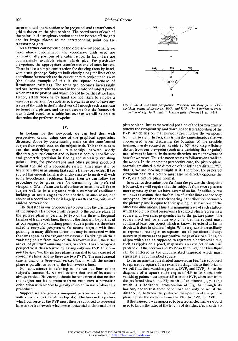
Fig. 4. (a) A one-point perspective. Principal vanishing point, PVP; vanishing points of diagonals, DVP, and DVP2. (b) A horizontal cross-
section of Fig. 4a through its horizon (after Pirenne [1, p. 142]).
picture plane. Just as the vertical position of the horizon exactly follows the viewpoint up and down, so the lateral position of the PVP (which lies on that horizon) must follow the viewpoint from left to right. In fact, this is just the same situation that we encountered when discussing the location of the sensible horizon, merely rotated to the side by 90?. Anything infinitely distant from our viewpoint (such as a vanishing line or point) must always be located in the same direction, no matter where or how far we move. Thus the moon seems to follow us on a walk in the woods. In the one-point perspective case, the picture-plane normals are aimed in the direction of the infinitely distant PVP; that is, we are looking straight at it. Therefore, the preferred viewpoint of such a picture must also lie directly opposite the PVP, on a picture plane normal.
In order to determine how far from the picture the viewpoint is located, we will require that the subject's framework possess more symmetry than we have assumed so far. Specifically, we will have to assume that the families of lattice lines are not only orthogonal, but also that their spacing in the direction normal to the picture plane is equal to their spacing in at least one of the other two dimensions. Thus, the minimum trace of such a lattice which the picture must preserve is a trapezoid which represents a square with two sides perpendicular to the picture plane. The square need not be shown explicitly, but the subject must contain at least one object which is known to extend as far in depth as it does in width or height. While trapezoids are as likely to represent rectangles as squares, an ellipse almost always occurs in pictures as the perspective image of a circle. Thus, an ellipse which can be supposed to represent a horizontal circle, such as ripples on a pond, may make an even better intrinsic yardstick. If the horizon and PVP can be found, then this ellipse can be enclosed in the circumscribed trapezoid which must represent a circumscribed square.
Let us assume that the shaded trapezoid in Fig. 4a is supposed to represent a square. If we extend its diagonals to the horizon, we will find their vanishing points, DVPi and DVP2. Since the diagonals of a square make angles of 45? to its sides, their vanishing points must appear 45? from the PVP, when seen from the preferred viewpoint. Figure 4b (after Pirenne [1, p. 142]) which is a horizontal cross-section of Fig. 4a through its horizon, shows that these conditions can only be met if the distance, d, between the preferred viewpoint and the picture plane equals the distance from the PVP to DVP1 or DVP2.
If the trapezoid was supposed to be a rectangle, then we would need to know the ratio of the lengths of its sides, a/b, in order to
100
This content downloaded from 195.34.78.78 on Wed, 18 Jun 2014 17:01:19 PMAll use subject to JSTOR Terms and Conditions

The Preferred Viewpoint in Linear Perspective
determine the viewpoint. In that case, its distance from the picture plane would be d(a/b). Clearly, then, a given trapezoid may be interpreted as either the 'telephoto' view from a distant viewpoint of a long, narrow rectangle (a>b), or the 'wide angle' view from a nearby viewpoint of a short, wide rectangle (b>a). More generally, a picture in one- or two-point perspective must portray some object of 'known' proportions if we are to be able to determine the total angular view encompassed by the picture. Only by means of some such intrinsic standard can the degree of foreshortening and/or marginal 'distortion' be judged.
Suppose now that we are given a two-point perspective (Fig. 5a), based again, for convenience, on a vertical picture plane. In this case we can begin to track down the preferred viewpoint by noting that it must still lie at the level of the horizon, but now there are two PVP's, which must appear 90? apart. This condition limits the viewpoint to a horizontal semicircle (Fig. 5b) with its endpoints at the PVP's (by Thale's theorem: if one side of a triangle inscribed in a circle is a diameter of that circle, then the opposite angle must be a right angle).
PVP DVP, PVP2 H , _-- --- - - _ - --..
to DVP2 -' '
a.
iPV vs D IP
PVe DVP, PVP
-V
.
1
"pp
b.
Fig. 5. (a) A two-point perspective. Principal vanishing points, PVP, and PVP2. (b) A horizontal cross-section of Fig. 5a through its horizon.
In order to specify a unique position on that semicircle, we will again require that the lattice lines be equally spaced in at least two dimensions; here these must be all the horizontal lines. In other words, the picture must show a trapezium (shaded in Fig. 5a) which can be assumed to be the image of a horizontal square. We must again find a vanishing point of the diagonals, by extending one to the horizon, but this no longer gives us a direct nomographic solution. That much is obvious from the fact that DVP, and DVP2 are generally no longer equidistant from either of the PVP's. We will concentrate on the vanishing point DVPI, which lies between the PVP's, but only by making calculations based on measurements of the picture will we be able to find the two unknown viewpoint coordinates.
As shown in Fig. 5b, we are given, as part of the picture, the distance, D, between the PVP's (which is the semicircle's diameter), and the distance, s, between PVPi and DVPI. Our goal is to find the distance, d, of the preferred viewpoint, 0, from the picture plane, and the lateral separation, x, between that viewpoint and PVP,.
From the equation of the semicircle,
[(D/2) - x]2 + (d)2 = (D/2)2, we have: x2 + d2 = Dx.
By the Pythagorean theorem, we can express the length of the segment from 0 to PVP1 as (x2 + d2)', and that from 0 to DVP1
as [(s - x)2 + de2]2. Since their enclosed angle must equal 45?, we have, by the law of cosines:
S2 = (x2 + d2) + [(s - x)2 + d2] - 2{(x2 + d2)[(s - x)2 + d2]}2 cos 45?, which reduces to:
[2(x2 + d2 - sX)]2 = 2(x2 + d2)(s2 - 2sx + x2 + d2).
Substituting in from the above semicircle equation gives:
[2(Dx - sx)]2 = 2(Dx)(s2 - 2sx + Dx), which can be solved for x, yielding:
x = Ds2/(D2 - 2Ds + 2S2).
By substitution into the semicircle equation again, we also obtain:
d = [Ds2(D3 - 2D2s + Ds2)]Y/(D2 - 2Ds + 2s2).
Note that in the limit as D approaches infinity, the picture degenerates to a one-point perspective, and so x =0 and d = s. It should also be noted that if the horizontal lattice lines lie at exactly 45? to the picture plane, then the diagonals themselves can be considered as the lattice lines of a one-point perspective in which the PVP's and DVP's have been transposed.
Strangely enough, pictures in three-point perspective (Fig. 6a) are easier to handle than two-point perspectives. There is a simple graphical procedure to determine the point in the picture which is directly opposite the preferred viewpoint, that is, its orthogonal projection on the picture plane: one merely connects the three PVP's with lines to form an acute triangle and then erects at least two of the altitudes of that triangle (Fig. 6b). Their intersection is the orthogonal projection of the viewpoint.
PVP, PVP,
I /
PVP, a.
H PVP2
/ D
D
Pa
b.
d' /
/
PVP
C.
Fig. 6. (a) A three-point perspective. Principal vanishing points, PVP,, PVP2, and PVP3. (b) The triangle formed by connecting the PVP's of Fig. 6a. Its altitudes intersect at point P. (c) A cross-section of Fig. 6b through
the points PVP3 and P.
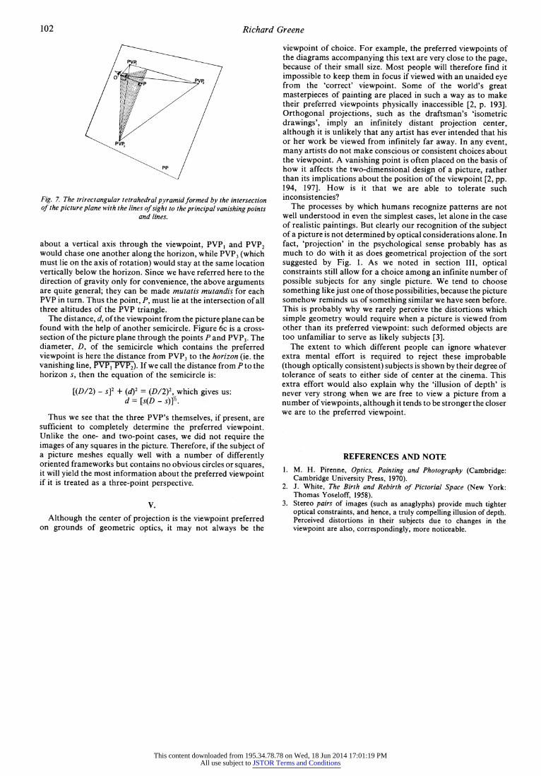
In order to see why this occurs, consider Fig. 7. It shows the trirectangular tetrahedral pyramid formed by the intersection of the picture plane with the lines of sight to the principal vanishing points and lines. Although this is the corner of a cube, it must not be confused with any structure which might exist as part of the subject; it is rather just the 'pyramid of sight' when observing the PVP's. The point, P, is the orthogonal projection of the preferred viewpoint, 0, on the picture plane. Thus the shaded plane, determined by P, 0 and PVP3, must be perpendicular to the picture plane. Since it contains the vertical line, 0 PVP3, it must also be perpendicular to the horizontal plane of 0, PVPi and PVP2. The intersection of this horizontal plane and the picture plane, the horizon line PVP, PVP2, must therefore also be perpendicular to the shaded plane. This means that the line PVP3 P has to lie on an altitude of the PVP triangle. In a more intuitive way, it is clear that if the picture plane were to rotate
101
This content downloaded from 195.34.78.78 on Wed, 18 Jun 2014 17:01:19 PMAll use subject to JSTOR Terms and Conditions
Richard Greene
Fig. 7. The trirectangular tetrahedral pyramid formed by the intersection of the picture plane with the lines of sight to the principal vanishing points
and lines.
about a vertical axis through the viewpoint, PVPi and PVP2 would chase one another along the horizon, while PVP3 (which must lie on the axis of rotation) would stay at the same location vertically below the horizon. Since we have referred here to the direction of gravity only for convenience, the above arguments are quite general; they can be made mutatis mutandis for each PVP in turn. Thus the point, P, must lie at the intersection of all three altitudes of the PVP triangle.
The distance, d, of the viewpoint from the picture plane can be found with the help of another semicircle. Figure 6c is a cross- section of the picture plane through the points P and PVP3. The diameter, D, of the semicircle which contains the preferred viewpoint is here the distance from PVP3 to the horizon (ie. the vanishing line, PVPi PVP2). If we call the distance from P to the horizon s, then the equation of the semicircle is:
[(D/2) - s]2 + (d)2 = (D/2)2, which gives us: d = [s(D - s)]/.
Thus we see that the three PVP's themselves, if present, are sufficient to completely determine the preferred viewpoint. Unlike the one- and two-point cases, we did not require the images of any squares in the picture. Therefore, if the subject of a picture meshes equally well with a number of differently oriented frameworks but contains no obvious circles or squares, it will yield the most information about the preferred viewpoint if it is treated as a three-point perspective.
V.
Although the center of projection is the viewpoint preferred on grounds of geometric optics, it may not always be the
viewpoint of choice. For example, the preferred viewpoints of the diagrams accompanying this text are very close to the page, because of their small size. Most people will therefore find it impossible to keep them in focus if viewed with an unaided eye from the 'correct' viewpoint. Some of the world's great masterpieces of painting are placed in such a way as to make their preferred viewpoints physically inaccessible [2, p. 193]. Orthogonal projections, such as the draftsman's 'isometric drawings', imply an infinitely distant projection center, although it is unlikely that any artist has ever intended that his or her work be viewed from infinitely far away. In any event, many artists do not make conscious or consistent choices about the viewpoint. A vanishing point is often placed on the basis of how it affects the two-dimensional design of a picture, rather than its implications about the position of the viewpoint [2, pp. 194, 197]. How is it that we are able to tolerate such inconsistencies?
The processes by which humans recognize patterns are not well understood in even the simplest cases, let alone in the case of realistic paintings. But clearly our recognition of the subject of a picture is not determined by optical considerations alone. In fact, 'projection' in the psychological sense probably has as much to do with it as does geometrical projection of the sort suggested by Fig. 1. As we noted in section III, optical constraints still allow for a choice among an infinite number of possible subjects for any single picture. We tend to choose something like just one of those possibilities, because the picture somehow reminds us of something similar we have seen before. This is probably why we rarely perceive the distortions which simple geometry would require when a picture is viewed from other than its preferred viewpoint: such deformed objects are too unfamiliar to serve as likely subjects [3].
The extent to which different people can ignore whatever extra mental effort is required to reject these improbable (though optically consistent) subjects is shown by their degree of tolerance of seats to either side of center at the cinema. This extra effort would also explain why the 'illusion of depth' is never very strong when we are free to view a picture from a number of viewpoints, although it tends to be stronger the closer we are to the preferred viewpoint.
REFERENCES AND NOTE
1. M. H. Pirenne, Optics, Painting and Photography (Cambridge: Cambridge University Press, 1970).
2. J. White, The Birth and Rebirth of Pictorial Space (New York: Thomas Yoseloff, 1958).
3. Stereo pairs of images (such as anaglyphs) provide much tighter optical constraints, and hence, a truly compelling illusion of depth. Perceived distortions in their subjects due to changes in the viewpoint are also, correspondingly, more noticeable.
102
This content downloaded from 195.34.78.78 on Wed, 18 Jun 2014 17:01:19 PMAll use subject to JSTOR Terms and Conditions