Embed Size (px)
Citation preview
Determination of the components of the gyrationtensor of quartz by oblique incidence
transmission two-modulatorgeneralized ellipsometry
Oriol Arteaga,1,* Adolf Canillas,1 and Gerald E. Jellison, Jr.2
1FEMAN Group, Departament de Física Aplicada i Òptica, IN2UB,Universitat de Barcelona, Barcelona 08028, Spain
2Oak Ridge National Laboratory, Oak Ridge, Tennessee 37830, USA
*Corresponding author: [email protected]
Received 31 July 2009; accepted 14 August 2009;posted 3 September 2009 (Doc. ID 115074); published 21 September 2009
The two independent components of the gyration tensor of quartz, g11 and g33, have been spectroscopi-cally measured using a transmission two-modulator generalized ellipsometer. The method is used to de-termine the optical activity in crystals in directions other than the optic axis, where the linearbirefringence is much larger than the optical activity. © 2009 Optical Society of America
OCIS codes: 260.1180, 260.1440, 160.1585, 240.2130.
1. Introduction
Optical activity is a property of materials relatedto different refractive indices for right- and left-circularly polarized light. Mathematically, optical ac-tivity is expressed as a complex frequency-dependentfunction, where the real dispersive part and theimaginary absorptive part are related through theKramers–Kronig relation. The dispersive part is re-ferred to as circular birefringence (CB), optical rota-tory power (ORP), or optical rotatory dispersion(ORD), whereas the absorptive part is referred toas circular dichroism (CD).The optical activity may be derived from a chiral
packing arrangement of the constituent moleculesor from the chirality of the individual molecules.In solid crystals the optical activity is normally asso-ciated with the absence of a center of symmetry inthe crystal structure, because the constituent mole-cules or atoms of crystals are not generally chiral.However, the optical activity in liquids is usually
due to the chirality of the individual molecules. Asa result, solid crystals tend to show much higherCB than liquids.
Optical activity was first observed by Arago [1] andBiot [2] in the early 1800s. The determination of CBhas been subject of extensive experimental study,particularly for many crystals. Alpha-quartz (SiO2)is probably the most studied, where the parametersof optical activity are known with great accuracy[3,4], as well as the variations with temperature andpressure [5,6]. As a result, quartz plates are routi-nely used as a standard of calibration for commercialpolarimeters. Most of the current measurements ofCB are performed along the unique direction in thecrystal (the c axis for quartz), which has no linear bi-refringence, isolating the CB. Therefore, most of thecommercial quartz crystals are cut perpendicular tothe c axis.
Although both linear birefringence and optical ac-tivity have been separately studied using a variety oftechniques, very few attempts have been made toquantify the optical activity in the presence of linearbirefringence. For transparent materials, an accu-rate measurement of CB cannot be made without
0003-6935/09/285307-11$15.00/0© 2009 Optical Society of America
1 October 2009 / Vol. 48, No. 28 / APPLIED OPTICS 5307

a full account of the related linear birefringence; forabsorbent materials, the linear dichroism and CDmust also be taken into account. In nature, circularand linear birefringent effects often appear together,so a method to measure CB in the presence of linearbirefringence is highly desirable. One such mea-surement technique is the high-accuracy universalpolarimeter (HAUP) [7–11]. This technique is a var-iation of the old technique of crossed polarizers, andit involves making measurements at slightly de-viated angles from the position of maximum extinc-tion of the polarizers. Typically, a monochromaticlight source is used and the values of the opticalactivity are determined from the evolution of the de-tected waveform as a function of the angle of rotationof the polarizers.The experimental approach we present is based on
the use of photoelastic modulators (PEMs). Foryears, accurate measurements of birefringence havebeen made by using PEMs that dynamically ellipti-cally polarize the input light [12,13]. PEMs are alsoemployed in CD spectrometers [14,15]. However,most of the reported techniques that use PEMs, al-though very accurate, only measure a few elementsof the sample Mueller matrix (in some cases, onlyone). One technique that can be used to measurethe complete sample Mueller matrix is the two-modulator generalized ellipsometer (2-MGE) [16,17].This powerful instrument uses two PEMs to comple-tely measure the polarization-dependent opticalproperties of any sample in reflection or transmis-sion, and has already been used to study the opticalactivity of organic materials [18].In this paper, we present a method to measure the
optical activity of crystals using the 2-MGE techni-que. Using this technique, it is possible to performmeasurements in directions other than along the op-tic axis of the crystal, where the magnitude of the lin-ear birefringence is significantly larger than themagnitude of the optical activity. As an applicationof this method we have measured the componentsof the gyration tensor of a right-handed (RH) anda left-handed (LH) quartz crystal.
2. Experimental
The 2-MGE was introduced by Jellison and Modinein 1997 [16,17]. In subsequent years the techniquewas used in transmission [19] and normal-incidencereflection configurations [20], both of which can beused to obtain x-y plots of the relevant parameters.The measurements presented herein were madewith a spectroscopic 2-MGE with a variable angleof incidence that is also capable of operating intransmission.The 2-MGE is composed of two polarizer–PEM
pairs, each of the PEMs operating at a differentresonant frequency (50 and 60kHz in this case),which is essential for frequency analysis. The firstpolarizer–PEM pair is used as the polarization stategenerator (PSG) on the input arm of the ellipsometer,while the second is used as the polarization state
analyzer (PSA) on the detection arm of the ellips-ometer. A PEM is a resonant device that is cut to os-cillate at a determinate frequency and acts as anoptical element with a time-dependent retardation.Both the operating frequency and the amplitude ofmodulation are very stable but, while the amplitudeof modulation can be easily controlled (usually withan external dc voltage), the frequency of oscillation(typically at 20–80kHz) is given by the geometryof the resonant bar.
A schematic of the optical train of the experimentalsetup is given in Fig. 1. The light source is a 75Wxenon arc lamp (Oriel) that is focused onto a quartzoptical fiber with a 1000 μm core. The end of the op-tical fiber is connected to amirror-based focusing sys-tem (Jobin-Yvon), resulting in a spot size from 2mmto 100 μm at the sample. The PSG is comprised of aRochon MgF2 polarizer and a PEM (Hinds Instru-ments) oscillating at 50kHz. The linear polarizeris attached to the PEM using a precision manual ro-tator and is oriented at 45° with respect to the PEMorientation. The PSG is attached to a stepper rota-tion stage (National Instruments UE31PP) so thatdifferent incoming polarization states can be inci-dent upon the sample.
The PSA has the same components as the PSG ex-cept for the operation frequency of the PEM, which,in this case, has a nominal frequency of 60kHz. ThePSA is also mounted on an automated rotator so thatdifferent polarization states coming from the samplecan be analyzed.
The light beam passing through the PSA is focusedonto a circular-to-rectangular quartz fiber bundle,which guides the light to the double grating mono-chromator (Jobin-Yvon DH10). The rectangular(200 μm × 6mm) end of the fiber acts as entrance slitof the monochromator. The light intensity is detectedat the output slit of the monochromator by using aphotomultiplier tube (PMT) (Hamamatsu R3896).The signal from the PMT is in the form of a photo-current and is converted to a voltage by using acurrent-mode preamplifier (Hamamatsu C7319).The voltage waveform from the preamplifier is cap-tured by using a computer digitizer board (SpectrumMI 3130) which is configured to capture 16,384 sam-ples in 8ms. As there are two modulators runningfree, each of them with its own phase, there is a trig-ger circuit that initializes the data capture when the
Fig. 1. Diagram of the experimental setup: 1, focusing system;2, polarizer; 3, PEM 0 (50kHz); 4, sample (tilted quartz plate);5, PEM 1 (60kHz); 6, analyzer; 7, lens. Light collected in 7 isguided by an optical fiber to a monochromator.
5308 APPLIED OPTICS / Vol. 48, No. 28 / 1 October 2009

two modulators are in phase. The computer board in-cludes programmable analog outputs that are usedto control the modulation amplitude of the PEMs,which is kept at A0 ¼ A1 ¼ 2:4048 rad [so thatJ0ðA0Þ≃ J0ðA1Þ≃ 0], and the gain introduced bythe PMT, so that the dc component of the signal iskept constant during measurement.The 2-MGE technique preserves the benefits of
conventional phase-modulated ellipsometry with theadvantage that is capable of measuring eight nor-malized Mueller matrix elements simultaneously.In contrast, the ellipsometers with only one photo-elastic modulator are limited to measuring only twoelements simultaneously. However, the interpreta-tion of the 2-MGE waveform is more complicated, be-cause at least eight frequency components have to bedetermined by Fourier analysis in one single mea-surement. For this work, the magnitude and phaseof 12 frequency components are determined in onesingle measurement, resulting in four of the eightparameters being measured twice. A detailed de-scription of the Fourier integral analysis of thetime-dependent detected intensity is given in [16].For most situations in which there is no depolari-
zation, a single measurement of 2-MGE is sufficientto completely determine the polarization-dependentoptical properties of a sample that could be describedwith a Mueller–Jones matrix. For a depolarizingsample, all the elements of the normalized Muellermatrix can be determined with four measurementsat different orientations of the azimuthal angles ofthe PSG and the PSA. Namely, these four configura-tions (PSG, PSA) are (0°, 0°), (0°, 45°), (45°, 0°), and(45°, 45°). In each one of these configurations, eightelements of the normalizedMueller matrix are deter-mined; therefore, some of the elements are overdeter-mined (for example, the elements m03, m30, and m33are measured four times) and, when this happens,the final values for these particular elements are theaveraged values.The geometry of the problem is shown in Fig. 2,
where the sample is quartz crystal with the c axisperpendicular to the optical faces of the sample. Alight beam is incident upon the crystal at an angle
of incidence ϕ with respect to its c axis. l, d, and θare, respectively, the light path through the crystal,the sample thickness, and the angle with respect tothe c axis of the wave normal for the wave propagat-ing through the crystal. If d and ϕ are known, thelight path l can be found by taking the approximationthat the wave normal (given by Snell’s law) in thecrystal coincides with the direction of propagation:
l ¼ dcos θ ; θ ¼ arcsin
�sinϕ�n
�; ð1Þ
where �n is the mean refractive index, which dependson θ and will be defined in Section 3. The sample wastilted in order to perform measurements at differentvalues for ϕ (which also means different values for θ).The rotation was around the y axis defined by themodulation axis of the PEMs when PSG and PSAare orientated at 0. A general scheme of the samplepositioning in the instrument is also shown in Fig. 1.
The various birefringence parameters are definedas follows:
LB ¼ 2πλ ðnx − nyÞl;
LB0 ¼ 2πλ ðn45 − n135Þl
CB ¼ 2πλ ðn− − nþÞl;
ð2Þ
where λ is the wavelength of light and the subscriptsspecify the polarization of light as x, y, 45° to the xaxis, 135° to the x axis, circular right þ, or left −.The circular birefringence is twice the optical rota-tion. The x-y linear birefringence LB is very sensitiveto sample tilt around the y axis, and so will be muchmore sensitive than the 45° LB0, which is expected tobe small.
The samples studied in this paper consist of two z-cut (c axis perpendicular to sample surface) quartzcrystals (SiO2) with opposite handedness. Crystal-line quartz (point group 32) is enantiomorphous, inthat it may occur as either right- or left-handed. Inorder to be enantiomorphous, a crystal must haveno element of symmetry that changes the handed-ness. For quartz, the atomic arrangement providesa screw axis that produces a helical distribution ofatoms, and the optical activity of the two types ofhandedness has opposite signs. We will present re-sults separately for the LH plate and for the RHplate. The measured thickness of the LH plate is1:02� 0:01mm, while the thickness of the RH plateis 1:06� 0:01mm.
In the case of quartz crystal, the CB is known to benonzero in a wide frequency region that includes thewhole studied spectrum (220 to 800nm) [21]. In thisregion quartz is not absorbent [22] and, therefore, allparameters related to the absorptive nature of thecrystal (including the CD) are zero.
3. Theory
The theory of light propagation in general anisotro-pic media often results in complicated equations. For
Fig. 2. Geometry of the off-normal-incidence measurement of cir-cular and linear birefringence.
1 October 2009 / Vol. 48, No. 28 / APPLIED OPTICS 5309

optical active crystals where the direction of lightpropagation is along the optical axis, the problemcan be treated with the phenomenological equationsthat are analogous to those used in isotropic systems,resulting in significant simplification. However, themore general case of oblique incidence requiressolving the Maxwell equations with modified con-stitutive equations, significantly complicating themathematics. To do so, several authors use the Ber-reman 4 × 4 matrix formulation of Maxwell equa-tions, but, even so, different approaches appear inthe literature since the choice of the constitutive re-lations is not unique [23]. We will use the propaga-tion description first given by [24], which uses theconstitutive equations given by Born [25]. This modelis widely used in the literature [23,26–28], particu-larly in experimental work, and gives the possiblevalues of the refractive index n, for a given directionof the wave normal. Although this approach is onlyapproximate, it has been shown to be accurate aslong as the birefringence of the investigated crystalis not huge [29], as this model describes the phenom-enon of optical activity within an accuracy of the pro-duct of the linear birefringence in the direction ofobservation by the gyrotropy parameters [28]. In thiscontext, the two possible refractive indices are givenby the positive roots of the equation [27,28]
ðn2 − n201Þðn2 − n2
02Þ ¼ G2; ð3Þ
where n01 and n02 are the refractive indices of the ei-genwaves in the absence of optical activity. G is thescalar gyration parameter and is a measure of theoptical activity for the direction in question. G as afunction of direction is given by
G ¼ gijlilj; ð4Þ
in which the convention of summing over repeatedindices is used. li and lj are the direction cosines ofthe normal wave and gij are the components of thegyration tensor that describe the optical activity ofthe crystal. In uniaxial crystals (g11 ¼ g22 ≠ g33) Gtakes the form [23]
G ¼ g11sin2θ þ g33cos2θ; ð5Þ
where θ is defined in Eq. (1).The solutions of Eq. (3) are [23]
n21;2 ¼ ½n2
01 þ n202∓½ðn2
02 − n201Þ2 þ 4G2�1=2�=2; ð6Þ
and, for a uniaxial crystal (ε11 ¼ ε22 ≠ ε33),
n201 ¼ ε11; n2
02 ¼ ε11ε33ðε11sin2θ þ ε33cos2θÞ
; ð7Þ
where ε11 ¼ εo ¼ n2o and ε33 ¼ εe ¼ n2
e . The refractiveindices no and ne of quartz are well known and aregiven by the five-parameter dispersion relation cal-culated in [30].
The total birefringence (TR) of the system is a com-bination of linear (LB and LB0) and circular (CB) bi-refringences:
T2R ¼ LB2 þ LB02 þ CB2; ð8Þ
with
TR ¼ 2πλ ðn2 − n1Þl; ð9Þ
and LB, LB0, and CB as defined in Eq. (2). Accordingto Eq. (6) and assuming that G2 ≪ n2
01n202, T
2R can be
approximated by
T2R ≃
4π2λ2
�ðn02 − n01Þ2 þ
G2
n01n02
�l2: ð10Þ
Because of the geometry of our oblique incidenceexperiment (see Fig. 2), the sample tilting does notcause birefringence in direction 45° to the x axis(LB0 ≃ 0) and LB itself can be considered as a mea-sure of the total linear birefringence. Therefore,Eq. (8) can be simplified to
T2R ≃ LB2 þ CB2: ð11Þ
Comparing Eq. (11) to Eqs. (10) and (8), we can makethe following identifications,
LB ¼ 2πλ ðn02 − n01Þl; ð12Þ
CB ¼ 2πGlλ �n ; ð13Þ
where �n stands for a mean refractive index�n ¼ ffiffiffiffiffiffiffiffiffiffiffiffiffiffi
n01n02p
.In the special case of propagation along the optic
axis (θ ¼ 0°) CB is proportional to the g33 componentof the gyration tensor:
g33 ¼ CBθ¼0°λno
2πl : ð14Þ
For light propagation along the optical axis in anoptically active uniaxial crystal or for light propaga-tion in any direction in an optically active isotropicmedium, the eigenmodes of optical propagationthrough the material are left and right circularly po-larized modes, each of which has its own refractiveindex. In contrast, the eigenmodes in a uniaxial ma-terial without optical activity are linearly polarizedmodes that are mutually orthogonal. As a result,in a random direction in an optically active uniaxialcrystal, the eigenmodes are left and right ellipticalpolarization modes with major axes that coincidewith the directions of the linearly polarized
5310 APPLIED OPTICS / Vol. 48, No. 28 / 1 October 2009

eigenmodes that would be present in the absence ofoptical activity.The ellipticity k is the ratio of the minor axis to the
major axis of the ellipse of polarization, and it can beused to define the waves that travel through the crys-tal unchanged in form. Along the optic axis, k ¼ 1,which indicates that the eigenmodes are circularlypolarized light. The quantity k can be calculatedas follows [27]:
k ¼ tan�γ2
�; ð15Þ
where γ is an angle defined by the ratio between thecircular and linear birefringences:
tan γ ¼ CBLB
: ð16Þ
With the relations of Eqs. (12) and (13), this ratio canbe written as
CBLB
¼ G�nðn02 − n01Þ
; ð17Þ
and, by substituting Eq. (5) here, we can derive anexpression to calculate g11 from experimental mea-surements of the ratio CB=LB:
g11 ¼ 1
sin2θ
��nðn02 − n01Þ
CBLB
− g33cos2θ�: ð18Þ
A. Model for the Dispersion of the Gyration TensorComponents
The first phenomenological models to describe theoptical activity appeared early in the 20th century[3,31], where the first tenuous connections weremade between optical rotation and the inter-action between atoms. One of the more successful ap-
proaches was carried out by Chandrasekhar usingclassical theory to study the optical rotation of quartz[21,32]. In this model there are two coupled oscilla-tors that represent the smallest unit of the opticallyactive crystal. The oscillators are assumed to be iden-tical and undamped (that is, the crystal is non-absorbing). This coupled-oscillator model can also betreated quantum mechanically and describes the op-tical rotation ρ of quartz in a wide frequency region:
ρ ¼ kλ2ðλ2 − λ20Þ2
: ð19Þ
The optical rotation ρ is related to CB by ρ ¼ 1=2CB,and k and λ0 are the two unique parameters ofthe model.
To measure the components of the gyration tensorG, we propose to use this dispersion model to para-meterize g11 and g33:
gii ¼Aiλ3
ðλ2 − B2i Þ2
; ð20Þ
where Ai and Bi are the parameters to be deter-mined. Note that this model can be straightforwardlyderived from Eq. (19) if we consider that G ¼ λ�nρ=πl[see Eq. (13)] and we use the approximation that �n isconstant. We have found that Eq. (20) is a good fit forour experimental g11 and g33 data. It is interesting tonote that, while for quartz, CB (∝ ðn− − nþÞ) varies bymore than 1 order of magnitude in the interval rangefrom 200 to 800nm, the variation of the mean refrac-tive index �nð∝ ðn− þ nþÞÞ) in this same interval isonly around 7%. Thus, it is not strange that, ifEq. (19) constitutes a good fit for CB, Eq. (20) can beused to fit the gyration tensor with success.
4. Data Analysis for the Mueller Matrix of Quartz
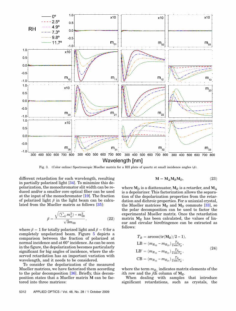
The spectroscopic Mueller matrices measured at dif-ferent small incident angles for RH and LH platesare, respectively, presented in Figs. 3 and 4. In bothcases, and for all the orientations of the plates, Muel-ler matrix elementsm01,m02,m03,m10,m20, andm30are approximately zero in all the studied spectralrange (note that these elements have beenmultipliedby a factor 10). This indicates that, at this wave-length range and for these small angles of incidence,there is not significant diattenuation and the Muel-ler matrices of the quartz plates basically take theform of a general retarder [33]:
MR ¼
0BB@
1 0 0 00 cosTR þ LB2α LBLB0αþ CBβ −LBCBαþ LB0β0 LBLB0α − CBβ cosTR þ LB02α −LB0CBα − LBβ0 −LBCBα − LB0β −LB0CBαþ LBβ cosTR þ CB2α
1CCA; ð21Þ
with α ¼ ð1 − cosTRÞ=T2R, β ¼ sinTR=TR, and
TR ¼ffiffiffiffiffiffiffiffiffiffiffiffiffiffiffiffiffiffiffiffiffiffiffiffiffiffiffiffiffiffiffiffiffiffiffiffiffiffiffiffiLB2 þ LB02 þ CB2
p.
However, a crystal with retardation propertiesthat vary rapidly with wavelength may induce depo-larization if the system collects a band of wave-lengths rather than a single wavelength. Since theretardation is proportional to the inverse of thewavelength, a band of wavelengths will result in a
1 October 2009 / Vol. 48, No. 28 / APPLIED OPTICS 5311
different retardation for each wavelength, resultingin partially polarized light [34]. To minimize this de-polarization, themonochromator slit width can be re-duced and/or a smaller core optical fiber can be usedat the input of the monochromator [19]. The fractionof polarized light β in the light beam can be calcu-lated from the Mueller matrix as follows [35]:
β ¼ffiffiffiffiffiffiffiffiffiffiffiffiffiffiffiffiffiffiffiffiffiffiffiffiffiffiffiffiffiffiffiffiðPij m
2ijÞ −m2
00
qffiffiffi3
pm00
; ð22Þ
where β ¼ 1 for totally polarized light and β ¼ 0 for acompletely unpolarized beam. Figure 5 depicts acomparison between the fraction of polarized atnormal incidence and at 60° incidence. As can be seenin the figure, the depolarization becomes particularlysignificant for big angles of incidence, where the ob-served retardation has an important variation withwavelength, and it needs to be considered.To consider the depolarization of the measured
Mueller matrices, we have factorized them accordingto the polar decomposition [36]. Briefly, this decom-position states that a Mueller matrix M can be fac-tored into three matrices:
M ¼ MΔMRMD; ð23Þ
whereMD is a diattenuator,MR is a retarder, andMΔis a depolarizer. This factorization allows the separa-tion of the depolarization properties from the retar-dation and dichroic properties. For a uniaxial crystal,the Mueller matrices MR and MD commute [33], sothe polar decomposition can be used to factor theexperimental Mueller matrix. Once the retardationmatrix MR has been calculated, the values of lin-ear and circular birefringence can be extracted asfollows:
TR ¼ arccosðtrðMRÞ=2 − 1Þ;LB ¼ ðmR32
−mR23Þ TR2 sinTR
;
LB0 ¼ ðmR13−mR31
Þ TR2 sinTR
;
CB ¼ ðmR12−mR21
Þ TR2 sinTR
;
ð24Þ
where the termmRijindicates matrix elements of the
ith row and the jth column of MR.When dealing with samples that introduce
significant retardations, such as crystals, the
Fig. 3. (Color online) Spectroscopic Mueller matrix for a RH plate of quartz at small incidence angles (ϕ).
5312 APPLIED OPTICS / Vol. 48, No. 28 / 1 October 2009

determination of the sample Mueller matrix may notbe sufficient to determine all its birefringent charac-teristics. In Eq. (21), it can be seen that many of theMueller matrix elements contain trigonometric func-tions. Furthermore, the arccosine, which is multiva-lued, is required to determine the total birefringence[see Eq. (24)]. For systems with small retardations,
this does not constitute a problem since the total re-tardation must fall in the ½0; π� interval. However, forsystems with big retardances (e.g., some crystals),this problem prevents us from determining the bire-fringences unless we know their order. For example,at 252nm, the Mueller matrix of the LH plateof quartz with an angle of incidence of 9° is thefollowing:
M ¼
2664
1 0:002 0:003 0:0060:005 1:002 0:009 0:0100:001 0:011 1:000 0:0020:000 0:010 −0:006 0:988
3775 ð25Þ
This matrix is nearly the same as the identity Muel-ler matrix, which one would obtain in transmissionfor an isotropic medium. Of course, the sample isnot isotropic, although its Mueller matrix appearsto be that of an isotropic medium at this wavelength.The importance of the order must always be consid-ered when analyzing these results, since a singleMueller matrix is not always sufficient to providethe characterization of a polarization element.
Fig. 4. (Color online) Spectroscopic Mueller matrix for a LH plate of quartz at small incidence angles (ϕ).
Fig. 5. (Color online) Fraction β of polarized light for normal andoblique incidence. For the same conditions, the RH plate is a bitmore depolarizing because it is a slightly thicker than the LHplate.
1 October 2009 / Vol. 48, No. 28 / APPLIED OPTICS 5313

For large angles of incidence, a significant lineardiattenuation appears in the measured Mueller ma-trices as they no longer have all the vanishing ele-ments shown in Eq. (21). In this case, the lineardiattenuation is not due to an anisotropic absorbancein quartz, but rather is caused by the different re-flectivities of s- and p-polarized light [13]. The polardecomposition allows us to obtain the linear diatte-nuation of the sample from the matrix factorMD [36].Figure 6(a) displays the linear diattenuation for aquartz plate at an angle of incidence of 60°.Figure 6(b) shows the total retardance TR as deter-
mined using the last equation of Eqs. (24) for the RHquartz plate with an incidence angle of 60°. At thislarge incident angle, the linear birefringence ofquartz is big compared to π, and the total retardancegoes through several oscillations between 0 and π asa function of wavelength. To determine the real TR,we should also know their order to unfold the “folded”spectrum of Fig. 6. Fortunately, we do not need toknow the order of the birefringence to determine theellipticity and the gyration tensor of quartz. Equa-tions (16) and (18) show that it is only necessaryto determine the ratio of CB to LB, rather than de-termining LB and CB separately. That is, we do nothave to determineTR. In terms ofMueller matrix ele-ments, the ratio CB=LB is given by
CBLB
¼ mR12−mR21
mR32−mR23
: ð26Þ
Therefore, the ratio CB=LB can be straightforwardlydetermined once the matrix MR is known. Although
Eq. (26) is a significant simplification, each of theMueller matrix elements must be measured accu-rately. Obviously, a large error occurs when the de-nominator (mR32
−mR23) approaches to zero, which
occurs at several wavelengths for these samples. For-tunately, as will be discussed in Section 5, thesepoints can be easily identified and can be removedfrom the calculation. Another experimental issue isthat the retardation oscillation frequency increasesat small wavelengths (see Fig. 6(b)), and the conse-cutive maxima and minima may be separatedonly by a few nanometers. Thus, a good spectralresolution as determined by the monochromator
Fig. 6. (a) Linear diattenuation and (b) “folded” total retardationTR induced by a 1mm thick, z-cut RH quartz plate at an incidenceangle of 60°.
Fig. 7. (Color online) Spectroscopic evolution of the ellipticity kfor small angles of incidence.
Fig. 8. (Color online) Measured components of the gyration ten-sor (∘) and fitted dispersion relation (solid line) for the RH plate.
5314 APPLIED OPTICS / Vol. 48, No. 28 / 1 October 2009

must be sufficient to resolve these oscillations. Thin-ner samples would also reduce the total retardationand, therefore, avoid this problem.
5. Results
We have examined the retarding properties of thequartz plates at angles slightly deviated from the po-sition of normal incidence by measuring their Muel-ler matrices. These measurements show the decreaseon the ellipticity k as we deviate from the optic axis.Figures 3 and 4, respectively, show the normalizedMueller matrix for a RH and a LH plate of quartzat small angles of incidence. Small deviations fromthe condition of normal incidence translate in ob-vious differences in the matrices, which indicatethat, even for situations close to the propagationalong the optical axis, the LB becomes comparableto CB. Qualitatively, these matrices resemble thematrix for a general retarder given in Eq. (21), wherethe different handedness is denoted by the oppositesigns that Mueller matrix elements m12, m21, m13,and m31 take in Figs. 3 and 4. Elements m23 andm32 do not change in sign, but this is due to the geo-metry of our oblique incidence measurements. Theonly elements that are not sensitive to the handed-ness of quartz, no matter the orientation of theplates, are the diagonal elements.Figure 7 shows the ellipticity k for the RH and LH
plates of quartz calculated from the values of LB and
CB according to Eq. (15). The ellipticity describes thepolarization state of the waves that propagateunchanged through the crystal. As expected, at nor-mal incidence, the ellipticity is 1 for the RH and −1for the LH, and it quickly diminishes as the angle ofincidence becomes more oblique. The points missingin Fig. 7 are points placed at wavelengths at whichthe total retardance TR is close to 2π, where accuratemeasurement of the ellipticity is not possible.
The measurement of the two independent compo-nents of the gyration tensor of quartz requires theorientation of the samples in two different configura-tions. The first measurement is made at normal in-cidence (θ ¼ ϕ ¼ 0°), where g33 is calculated usingEq. (14). This is the usual measurement configura-tion when the sample does not show LB, so the deter-mination is straightforward. The determination ofg11 is obtained using Eq. (18) and requires thatthe measurements be taken at a large incidence an-gle to avoid small values for the sin θ that wouldtranslate into large errors in g11. We have chosen ϕ ¼60° (θ ∼ 33°), which is close to the maximum inci-dence angle for which we can guarantee that both theextraordinary and ordinary rays are collected by thedetector.
The experimental values and the fitted curves forthe g11 and g33 components of the RH and the LHquartz plates are shown in Figs. 8 and 9. The fittingto the model of Eq. (20) has been performed with aweighted Levenberg–Marquadt nonlinear minimiza-tion procedure using the reduced χ2 as a figure ofmerit. Not all the experimental points have beenused for the fitting (see Figs. 8(b) and 9(b)), since wehave only used those points that correspond to wave-lengths for which the ratio CB=LB can be measured
Fig. 9. (Color online) Measured components of the gyrationtensor (∘) and fitted dispersion relation (solid line) for the LHplate.
Table 1. Fitted Parameters for the Model in Eq. (20) with λExpressed in Nanometers
Component LH RH
g11 A1 ¼ 0:0277� 0:0017 A1 ¼ −0:0298� 0:0015B1 ¼ 105:6� 5:7 B1 ¼ 91:1� 4:2χ2 ¼ 0:82 χ2 ¼ 0:59
g33 A3 ¼ −0:0609� 0:0002 A3 ¼ 0:0604� 0:0005B3 ¼ 97:54� 0:05 B3 ¼ 97:33� 0:05χ2 ¼ 1:33 χ2 ¼ 0:94
Table 2. Comparison of Data for the Components of the GyrationTensor of Quartz at Room Temperature Determined fromthis Study and from Selected Values in the Literature
Wavelength (nm) Reference jg33j × 10−5 jg11j × 10−5
632.8 [11] 10:1� 0:2 5:9� 0:4[10] 10.11 6.11[37] 13:6� 0:5 5:7� 0:5[39] 10.528 5.39[8] - ∼5:2
This worka 10:06� 0:07 4:8� 0:5510 [24] 12:96� 0:2 5:82� 0:4
[8] - ∼6:5This worka 12:81� 0:08 6:1� 0:6
aValues obtained from the average of RH and LH results.
1 October 2009 / Vol. 48, No. 28 / APPLIED OPTICS 5315

with highest accuracy. In particular we have onlyconsidered points for which jmR32
−mR23j=2 ≥ 0:98,
i.e., points for which the absolute value of the de-nominator of Eq. (26) is near its maximum value.Table 1 summarizes the fitting parameters for the
four fits presented in Figs. 8 and 9. In all cases, thedispersion relation given in Eq. (20) constitutes agood fit for experimental g33 and g11 data. Althoughthe accuracy of g11 is considerably lower than g33, it isclear that the shape of the dispersion curves for bothcomponents are fairly similar.A comparison between our data and some of the
previously published data is presented in Table 2,at two wavelengths. There are few experimentalmeasurements of g11 of quartz available in the litera-ture and most of them are restricted to a single wa-velength. With the exception of Ref. [37], our resultsagree with literature values for g33 within the statederror limits, and the agreement for g11 is within 2standard deviations with all the literature values.We also calculated the experimental ratio of the
two gyration tensor components g11=g33. In the non-absorptive wavelength regime, this ratio should be−0:5 due to a symmetry argument that applies tothe tetrahedron building units of crystalline quartz[38]. Figure 10 shows our spectroscopic experimentalresults for the g11=g33 ratio. They are consistent withthe symmetry argument as most points are within5% of the theoretical ideal value, and the calculatedmean value is −0:486� 0:028. By using this value inEq. (5), we can deduce that there is no optical rota-tion (G ¼ 0), that is, there exists an isotropic point forthe optical activity that is cylindrically symmetricaround the optic axis, for propagation directed∼55° from the optic axis.
6. Conclusion
We have presented a technique for measuring the op-tical activity in uniaxial crystals in situations whereboth linear birefringence and circular birefringent ef-fects are present. Hence, this technique allows one tomeasure the CB of optically active crystals in direc-tions different from the optical axis. This techniquehas been applied to the measurement of the two in-
dependent components of the gyration tensor of RHand LH crystalline quartz. The basis of the techniqueis the measurement of the ellipticity for the wavesthat transmit unchanged in their state of polariza-tion through the crystal. For directions out of the op-tical axis, the ellipticity of these waves is very smalland precise measurements require a highly sensitiveexperimental approach, such as provided by a trans-mission 2-MGE experiment. To our knowledge, thisis the first description of a systematic methodology toobtain spectroscopic measurements of the optical ac-tivity in crystals for direction out of the optic axis.
The presented results show the ability of the 2-MGE to deal with the phenomenon of optical activityin the presence of LB. Although the 2-MGE is a sui-table instrument for this kind of measurement, wehave presented a general approach to the measure-ment procedure for any instrument capable of mea-suring a sample Mueller matrix. We start from thebasis that the Mueller matrix of the crystal can bemeasured, and we demonstrate how effects inherentto the optical activity can be extracted from the ma-trix even when much higher linear birefringence ispresent. Today there exist several different instru-ments that are capable of determining the Muellermatrix of a sample, so this method could be appliedin several laboratories.
Another advantage of this technique is that differ-ent components of the gyration tensor of the crystalcan be determined without having to use samples cutaccording to several different crystallographicplanes. This is because we do not exclusively analyzelight transmitted in directions perpendicular tothese planes; besides, we also use a more general ob-lique incidence configuration in which more than onecomponent of the gyration tensor is contributing tothe observed optical activity. As an example, we havemeasured the g11 and g33 components of quartz usingonly a z-cut crystal with light incident at 60° from theoptic axis. In this configuration, both components g11and g33 contribute to the optical activity, but, as g33can be well determined from normal incidence mea-surements, the only remaining incognita is g11.
We envision that a similar approach to the one pre-sented here can be used for several other crystalswith point groups 3, 4, 6, 32, 422, and 622 (interna-tional notation), which are optically active and haveLB. Moreover, this technique may also be useful forcrystals with point groups �4 and �42m, which do notshow optical activity for light propagating along theoptic axis, but do show optical rotation in directionswhere there is also birefringence.
O. Arteaga and A. Canillas acknowledge financialsupport from the Spanish government (AYA2006-1648-C02-01). O. A. also acknowledges financial sup-port from the Ministerio de Educación y Ciencia(MEC) of Spain (FPU AP2006-00193). G. E. Jellisonacknowledges the financial support of the Division ofMaterials Science and Engineering, Office of BasicEnergy Sciences, U.S. Department of Energy (DOE),under contract DE-AC05-00OR22725 with Oak
Fig. 10. (Color online) Ratio of the two independent gyration ten-sor components g11=g33.
5316 APPLIED OPTICS / Vol. 48, No. 28 / 1 October 2009

Ridge National Laboratory, managed and operatedby UT-Battelle, LLC. We thank J. M. Ribó for moti-vating the research.
References1. D. F. Arago, “Sur une modification remarquable qu’ éprouvent
les rayons lumineux dans leur passage à travers certainscorps diaphanes, et sur quelques autres nouveaux phénom-ènes d’optique,” Mem. Inst. 1, 93–134 (1811).
2. J. B. Biot, “Mémoire sur un nouveau genre d’oscillations queles molécules de la lumière éprouvent, en traversant certainscristaux,” Mem. Inst. 1, 1–372 (1812).
3. T. M. Lowry, “Optical rotatory dispersion. Part I: The naturaland magnetic rotatory dispersion in quartz of light in the visi-ble region of the spectrum,” R. Soc. London Philos. Trans. A212, 261–297 (1913).
4. C. Chou, Y.-C. Huang, and M. Chang, “Precise optical activitymeasurement of quartz plate by using a true phase-sensitivetechnique,” Appl. Opt. 36, 3604–3609 (1997).
5. D. Yogev-Einot and D. Avnir, “The temperature-dependent op-tical activity of quartz: from le châtelier to chirality mea-sures,” Tetrahedron: Asymmetry 17, 2723–2725 (2006).
6. M. B. Myers and K. Vedam, “Effect of pressure on the opticalrotatory power and dispersion of crystalline sodium chlorate,”J. Opt. Soc. Am. 57, 1146–1148 (1967).
7. J. Kobayashi and Y. Uesu, “A new optical method and appa-ratus ‘HAUP’ for measuring simultaneously optical activityand birefringence of crystals. I. Principles and construction,”J. Appl. Crystallogr. 16, 204–211 (1983).
8. J. R. L. Moxon, A. R. Renshaw, and I. J. Tebbutt, “The simulta-neous measurement of optical activity and circular dichroisminbirefringent linearlydichroic crystal sections. II.Descriptionof apparatus and results for quartz, nickel sulphate hexahy-drate and benzil,” J. Phys. D 24, 1187–1192 (1991).
9. J. R. L. Moxon and A. R. Renshaw, “The simultaneous mea-surement of optical activity and circular dichroism in birefrin-gent linearly dichroic crystal sections. I. Introduction anddescription of the method,” J. Phys. Condens. Matter 2,6807–6836 (1990).
10. C. Hernandez-Rodriguez and P. Gomez-Garrido, “Optical ani-sotropy of quartz in the presence of temperature-dependentmultiple reflections using a high-accuracy universal polari-meter,” J. Phys. D 33, 2985–2994 (2000).
11. P. Gomez and C. Hernandez, “High-accuracy universal polari-meter measurement of optical activity and birefringence ofα-quartz in the presence of multiple reflections,” J. Opt.Soc. Am. B 15, 1147–1154 (1998).
12. B. Wang and T. C. Oakberg, “A new instrument for measuringboth the magnitude and angle of low level linear birefrin-gence,” Rev. Sci. Instrum. 70, 3847–3854 (1999).
13. G. E. Jellison, Jr., and C. M. Rouleau, “Determination of op-tical birefringence by using off-axis transmission ellipsome-try,” Appl. Opt. 44, 3153–3159 (2005).
14. A. F. Drake, “Polarisation modulation-themeasurement of lin-ear and circular dichroism,” J. Phys. E 19, 170–181 (1986).
15. L. A. Nafie, “Dual polarization modulation: a real-time, spec-tral-multiplex separation of circular dichroism from linearbirefringence spectral intensities,” Appl. Spectrosc. 54,1634–1645 (2000).
16. G. E. Jellison, Jr., and F. A. Modine, “Two-modulator general-ized ellipsometry: theory,” Appl. Opt. 36, 8190–8198 (1997).
17. G. E. Jellison, Jr., and F. A. Modine, “Two-modulator general-ized ellipsometry: experiment and calibration,” Appl. Opt. 36,8184–8189 (1997).
18. O. Arteaga, A. Canillas, R. Purrello, and J. Ribó, “Evidence ofinduced chirality in stirred solutions of supramolecular nano-fibers,” Opt. Lett. 34, 2177–2179 (2009).
19. G. E. Jellison, Jr., C. O. Griffiths, D. E. Holcomb, andC. M. Rouleau, “Transmission two-modulator generalizedellipsometry measurements,” Appl. Opt. 41, 6555–6566(2002).
20. G. E. Jellison, Jr., J. D. Hunn, and C. M. Rouleau, “Normal-incidence generalized ellipsometry using the two-modulatorgeneralized ellipsometry microscope,” Appl. Opt. 45,5479–5488 (2006).
21. S. Chandrasekhar, “Optical rotatory dispersion of crystals,”Proc. R. Soc. A 259, 531–553 (1961).
22. G. L. Tan, M. F. Lemon, D. J. Jones, and R. H. French, “Opticalproperties and London dispersion interaction of amorphousand crystalline SiO2 determined by vacuum ultraviolet spec-troscopy and spectroscopic ellipsometry,” Phys. Rev. B 72,205117 (2005).
23. A. Konstantinova, B. Nabatov, E. Evdishchenko, and K. Kon-stantinov, “Modern application packages for rigorous solutionof problems of light propagation in anisotropic layered media.II. Optically active crystals,” Crystallogr. Rep. (Transl. Kris-tallografiya) 47, 815–823 (2002).
24. G. Szivessy and C. Münster, “Über die prüfung der gitteroptikbei aktiven kristallen,” Ann. Phys. 412, 703–736 (1934).
25. M. Born, Optik: Ein Lehrbuch der Elektromagnetische Licht-theorie (Springer, 1933).
26. W. Kaminsky, “Experimental and phenomenological aspects ofcircular birefringence and related properties in transparentcrystals,” Rep. Prog. Phys. 63, 1575–1640 (2000).
27. J. F. Nye, Physical Properties of Crystals: Their Representationby Tensors and Matrices (Oxford U. Press, 1985).
28. A. Konstantinova, E. Evdishchenko, and K. Imangazieva,“Manifestation of optical activity in crystals of different sym-metry classes,” Crystallogr. Rep. (Transl. Kristallografiya) 51,998–1008 (2006).
29. D. Eimerl, “Quantum electrodynamics of optical activity inbirefringent crystals,” J. Opt. Soc. Am. B 5, 1453–1461(1988).
30. G. Ghosh, “Dispersion-equation coefficients for the refractiveindex and birefringence of calcite and quartz crystals,” Opt.Commun. 163, 95–102 (1999).
31. T. Bradshaw and G. H. Livens, “The formula for the opticalrotatory dispersion of quartz,” Proc. R. Soc. A 122, 245–250(1929).
32. S. Chandrasekhar, “Simple model for optical activity,” Am. J.Phys. 24, 503–506 (1956).
33. O. Arteaga and A. Canillas, “Pseudopolar decomposition of theJones and Mueller–Jones exponential polarization matrices,”J. Opt. Soc. Am. A 26, 783–793 (2009).
34. S.-L. Lu and A. P. Loeber, “Depolarization of white light by abirefringent crystal,” J. Opt. Soc. Am. 65, 248–251 (1975).
35. R. A. Chipman, Handbook of Optics, Vol. 2: Devices, Measure-ments, and Properties, 2nd ed. (McGraw-Hill, 1994),Chap. 22, p. 22.31.
36. S.-Y. Lu and R. A. Chipman, “Interpretation of Mueller ma-trices based on polar decomposition,” J. Opt. Soc. Am. A 13,1106–1113 (1996).
37. J. Kobayashi, T. Asahi, S. Takahashi, and A. M. Glazer, “Eval-uation of the systematic errors of polarimetric measurements:application to measurements of the gyration tensors of α-quartz by the HAUP,” J. Appl. Crystallogr. 21, 479–484(1988).
38. J. Jerphagnon and D. S. Chemla, “Optical activity of crystals,”J. Chem. Phys. 65, 1522–1529 (1976).
39. A. Konstantinova, K. Rudoy, B. Nabatov, E. Evdishchenko,V. Stroganov, and O. Pikul’, “The influence of optical activityon the intensity and polarization parameters of transmittedlight in crystals,” Crystallogr. Rep. (Transl. Kristallografiya)48, 823–831 (2003).
1 October 2009 / Vol. 48, No. 28 / APPLIED OPTICS 5317