Embed Size (px)
Citation preview
J. Mater. Environ. Sci. 7 (5) (2016) 1773-1790 Ghanooni-bagha et al.
ISSN : 2028-2508
CODEN: JMESCN
1773
Determination of Homogeneous Stiffness Matrix for Masonry Structure by
means of Homogenizing Theorem
Mohammad Ghanooni-bagha1*
, Mahdi Tarvirdi Yaghbasti2, Mohammad Reza Ranjbar3
1*Department of civil Engineering, East Tehran Branch, Islamic Azad University, Tehran, Iran
2School of Civil Engineering, Iran University of Science and Technology, Narmak, Tehran, Iran
3Technical Faculty of Mapping, ZabolUniversity, Zabol, Iran
Received 24 Nov 2015, Revised 24 Feb 2016, Accepted 29 Feb 2016
Corresponding*: [email protected]
Abstract
According to homogenizing theorem, heterogeneous or composite materials can be transformed to
homogeneous materials by means of constant elastic classical displacements with effective elastic constants
which indicate average characteristics of non-homogeneous environment.Most of the methods deliver the
homogenized stiffness matrix as a function of constituent materials: mortar and brick, their volume fraction and
the geometrical arrangement of masonry. In this paper, homogenized stiffness matrix for a single layer masonry
wall is obtained by two existing homogenizing methods Reuss,& Voigt and an innovative proposed model.
Then, the results are compared withthe results ofLorenco Method &finite element analysis method. Finally, in
the present study, the comparisons and analyses proved the accuracy andefficiency ofinnovative proposed
modelwith detail.
Keywords: Homogenizing, Masonry, Modeling, Representative Volume Element, Finite Element
Introduction
Developing of a proper analytical method for masonry structure has two major consequences: a) in analyzing
present masonry buildings and also masonry behavior of buildings with other structural systems; b) analysis of
old and historical building's behaviour that maintenance and restoring of them is particularly important.
Most of the methods used in the masonry building analysis are based on finite element analyses. These methods
have enough accuracy and give proper results but also are very time-consuming and need large memory space;
hence makes them to be not applicable for real structures. As a result, in recent decades many investigations
have been performed in order to conquer the issues related to building analysis. One of the appropriate solutions
is homogenizing technique. By complete development of this method many analytical concerns may diminish
and masonry analysis will be as plain as steel and concrete structure's analysis. In fact, the homogenizing
technique is based upon mechanical properties and overall masonry behaviour according to mechanical and
geometrical properties of constituent materials [1].
In this paper two of the existing methods and another proposed model are introduced. Then, the results are
compared with each other, Lourenco method and finite element analysis. In the proposed model in addition to
constituent's characteristics and their volume fraction, masonry geometrical arrangement is also considered.
Moreover, elasticity coefficients ratio of brick to mortar have a dominant role in the case that mortar quality has
decreased. The proposed model also considers this matter. It worth mentioning that many researchers have done
lots of investigations on the context among them) [2] was founder of the method) [3-9] in linear field and [10] in
nonlinear field, also for dynamic loading [11] can be referred. In the following sections, determination of the
RVE is introduced and other explanations will follow after.
J. Mater. Environ. Sci. 7 (5) (2016) 1773-1790 Ghanooni-bagha et al.
ISSN : 2028-2508
CODEN: JMESCN
1774
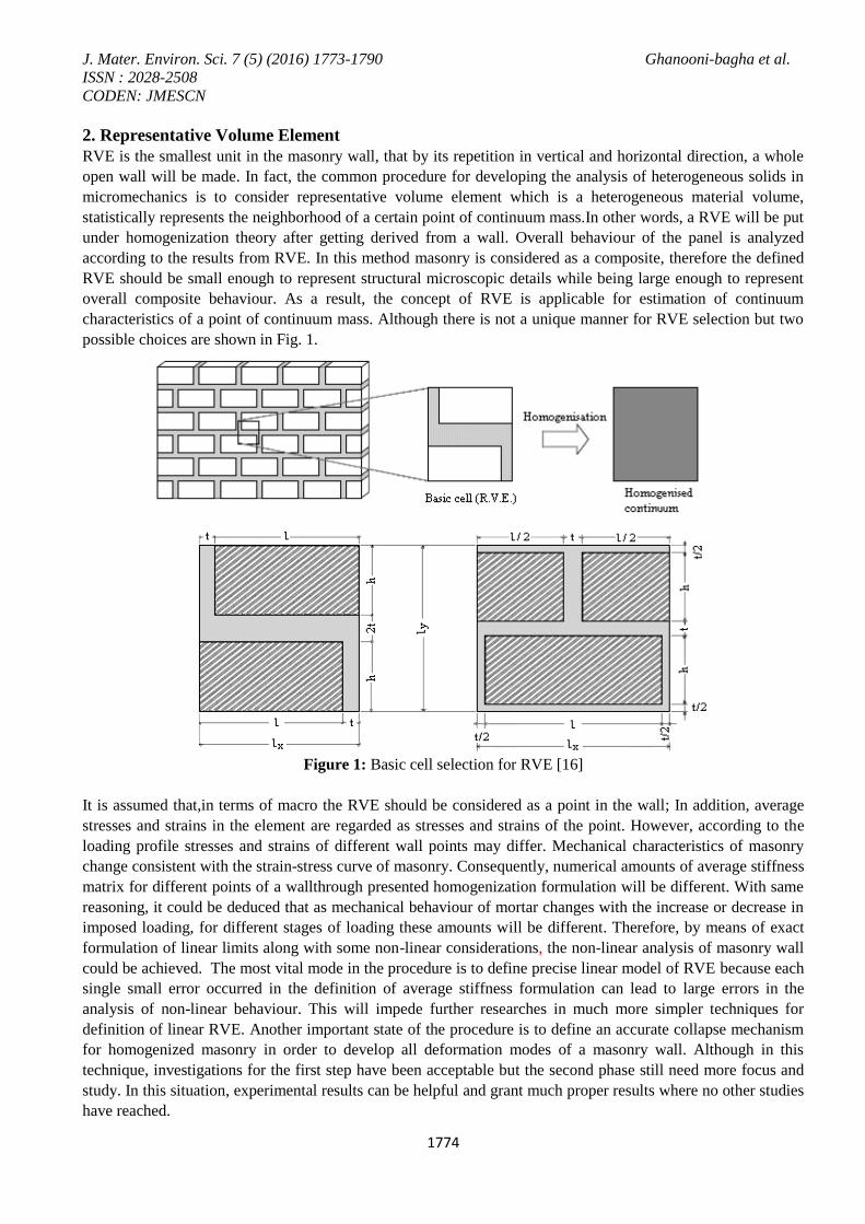
2. Representative Volume Element
RVE is the smallest unit in the masonry wall, that by its repetition in vertical and horizontal direction, a whole
open wall will be made. In fact, the common procedure for developing the analysis of heterogeneous solids in
micromechanics is to consider representative volume element which is a heterogeneous material volume,
statistically represents the neighborhood of a certain point of continuum mass.In other words, a RVE will be put
under homogenization theory after getting derived from a wall. Overall behaviour of the panel is analyzed
according to the results from RVE. In this method masonry is considered as a composite, therefore the defined
RVE should be small enough to represent structural microscopic details while being large enough to represent
overall composite behaviour. As a result, the concept of RVE is applicable for estimation of continuum
characteristics of a point of continuum mass. Although there is not a unique manner for RVE selection but two
possible choices are shown in Fig. 1.
Figure 1: Basic cell selection for RVE [16]
It is assumed that,in terms of macro the RVE should be considered as a point in the wall; In addition, average
stresses and strains in the element are regarded as stresses and strains of the point. However, according to the
loading profile stresses and strains of different wall points may differ. Mechanical characteristics of masonry
change consistent with the strain-stress curve of masonry. Consequently, numerical amounts of average stiffness
matrix for different points of a wallthrough presented homogenization formulation will be different. With same
reasoning, it could be deduced that as mechanical behaviour of mortar changes with the increase or decrease in
imposed loading, for different stages of loading these amounts will be different. Therefore, by means of exact
formulation of linear limits along with some non-linear considerations, the non-linear analysis of masonry wall
could be achieved. The most vital mode in the procedure is to define precise linear model of RVE because each
single small error occurred in the definition of average stiffness formulation can lead to large errors in the
analysis of non-linear behaviour. This will impede further researches in much more simpler techniques for
definition of linear RVE. Another important state of the procedure is to define an accurate collapse mechanism
for homogenized masonry in order to develop all deformation modes of a masonry wall. Although in this
technique, investigations for the first step have been acceptable but the second phase still need more focus and
study. In this situation, experimental results can be helpful and grant much proper results where no other studies
have reached.
J. Mater. Environ. Sci. 7 (5) (2016) 1773-1790 Ghanooni-bagha et al.
ISSN : 2028-2508
CODEN: JMESCN
1775
Even with uniform traction boundaries or linear boundary displacements, displacement field u(x)u , strain
field E(x)E , and stress field T(x)T in RVE will change from point to point. It should be mentioned that
in both situations of added surface data, RVE should be in equilibrium and its overall deformation compatible.
The governing field equilibrium equation at a typical point x in the volume V of the RVE is: T. ( ) ; T(x) T (x) inV T x o
(1)
Where body forces are absent and subscript T indicates transpose. Moreover, operator is defined as:
i i i
i
e ex
(2)
Besides equilibrium equations, strain-displacement equations should be considered as follows:
T1
E(x ) u u inV2 (3)
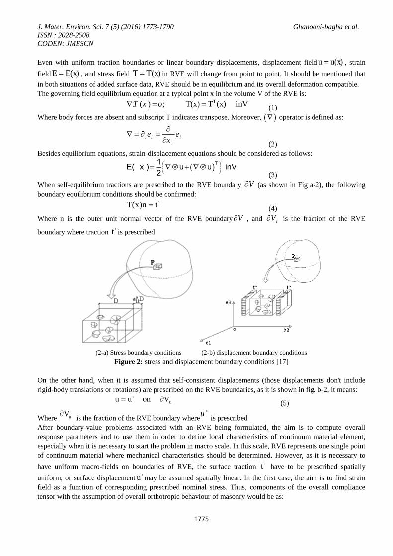
When self-equilibrium tractions are prescribed to the RVE boundary V (as shown in Fig a-2), the following
boundary equilibrium conditions should be confirmed: tn)x(T (4)
Where n is the outer unit normal vector of the RVE boundary V , and tV is the fraction of the RVE
boundary where traction t is prescribed
(2-a) Stress boundary conditions (2-b) displacement boundary conditions
Figure 2: stress and displacement boundary conditions [17]
On the other hand, when it is assumed that self-consistent displacements (those displacements don't include
rigid-body translations or rotations) are prescribed on the RVE boundaries, as it is shown in fig. b-2, it means:
uVon uu
(5)
Where uV is the fraction of the RVE boundary where
u
is prescribed
After boundary-value problems associated with an RVE being formulated, the aim is to compute overall
response parameters and to use them in order to define local characteristics of continuum material element,
especially when it is necessary to start the problem in macro scale. In this scale, RVE represents one single point
of continuum material where mechanical characteristics should be determined. However, as it is necessary to
have uniform macro-fields on boundaries of RVE, the surface traction t have to be prescribed spatially
uniform, or surface displacementu may be assumed spatially linear. In the first case, the aim is to find strain
field as a function of corresponding prescribed nominal stress. Thus, components of the overall compliance
tensor with the assumption of overall orthotropic behaviour of masonry would be as:
J. Mater. Environ. Sci. 7 (5) (2016) 1773-1790 Ghanooni-bagha et al.
ISSN : 2028-2508
CODEN: JMESCN
1776
S
S 1 1 .
ijijhk ij hk
hk
ijijhk ij hk
hk
ComponentsShear
ComponentsAxial
(6)
Where consistent considerations are held for defining the proper average strain field with the intention to use in
calculations. In the second case, the aim is to find the average stress field as a function of the corresponding
prescribed nominal strain. As a result, the components of the overall stiffness tensor are:
1 1 .
ijC
ijhk ij hkhk
ijC
ijhk ij hkhk
ComponentsShear
ComponentsAxial
(7)
Where consistent considerations are done for defining the proper average stress field to use in the calculations.
3. Compliance tensors and overall elastic modulus
In this section, volume V of the Representative volume Element with boundary of V is taken into account
which consists of a uniform elastic mortar with elasticity and compliance tensors: MC ,
MS . Alsoit consists of n
blocks with volume where each block has elasticity and compliance tensors
C , nS ,...,2,1 . It is
supposed that blocks are perfectly jointed with mortar; all the constituents of the RVE are assumed linear.
Hence, overall response of the RVE is linearly elastic. Overall compliance and elasticity tensors (average) of the
RVE are indicated respectively by C , S and as follows are estimated in terms of RVE's micro-structural
properties and geometry. As it was mentioned before, the prescribed macro-stress case and the prescribed
macro-strain case are studied separately.
3.1.case of prescribed constant macro-stress
For the constant macro-stress ( ) boundary tractions are:
Von .nt (8)
Because of the heterogeneity characteristics of the masonry, neither of the stress fields nor strain fields produced
in the RVE is uniform. Constant strain field E is defined as:
:SE (9)
Considering that the actual stress field is denoted by )x(T and the actual strain field is represented by )x(E ,
the following equations could be derived:
)x(EE)x(E
)x(T)x(T
d
d
(10)
Where xTd and xEd
are variable stress and strain fields, represents disturbances or perturbations in the
prescribed uniform stress field , which is due to heterogeneous RVE. Therefore, stress and strain tensors T
and E are associated with each other by Hook's law:
: ( ) : ( ) in V-( ) ( )
: ( ) : ( ) in
d
d
d
C E x C E E xT x T x
C E x C E E x
(11)
J. Mater. Environ. Sci. 7 (5) (2016) 1773-1790 Ghanooni-bagha et al.
ISSN : 2028-2508
CODEN: JMESCN
1777
in )x(T:S)x(T:S
-Vin )x(T:S)x(T:S)x(EE)x(E
d
d
d
(12)
Where 1
n
is the overall volume of total blocks; M indicates mortar volume.
According to averaging theorem [8]: )x(TT (13)
Where <> indicates average. From another point of view, overall average strain field is represented by:
)x(EE)x(EE d (14)
Hence, for the prescribed macro-stress:
0)x(Ed (15)
In order to calculate the overall compliance tensor S from:
: :E S T S (16)
The average amount of stress and strain field in each block and mortar should be calculated as follows:
1( ) ( )
1( ) ( )
i
i
i
i i
i
i i
E E x E x dV
T T x T x dV
(17)
Where i=α, M.
For the average stress and strain on mortar and blocks we have:
:
:
E S T
E S T
(18)
Therefore,
T:Sf:SEfEEfn
1
n
1
M
(19)
And
Tf:ST:SfEfn
1
MM
(20)
Consequently, it could be obtained that:
1 1
( ) : ( ) : ( ) : ( )n n
M M M dS S f S S T f S S T x
(21)
Where fV
denote volume fraction of the the block, and
M
Mf
V indicates volume fraction of the
mortar.
Equation (21) leads us to an exact result in achieving S . From (21), overall compliance tensor S is defined in
terms of average stress in blocks. The important point is that this result does not require entire stress field in
each block, but only the estimation of average values in each block is necessary.
Since the overall response is linearly elastic, disturbances or perturbations in stress and strain fields,
)x(T),x(E dd, are linear homogeneous functions of constant prescribed macro-stress
. Therefore, we have:
:HT:)SS()x(T:)SS( MdM
(22)
Where constant fourth order tensor H is defined as:
:)(:)(:)( ~~
HxTSxEETSE dMdM
(23)
J. Mater. Environ. Sci. 7 (5) (2016) 1773-1790 Ghanooni-bagha et al.
ISSN : 2028-2508
CODEN: JMESCN
1778
This is the change occurred in the average strain field , if
S is replaced byMS .
Since is arbitrary, by substitution of (22) in (21):
HfSSn
1
M
(24)
which is an exact result for a finite RVE as well as infinitely extended RVE. Restrictions of the above equation
is homogeneous and elastic blocks and mortar, blocks should be without defects and being completely joint to
mortar. However, some overall estimations and specializations are done in order to obtain constant tensors
),...,2,1( nH [17].
3.2.case of prescribed constant macro-strain
For constant macro-strain , boundary condition for the RVE is:
on Vu (25)
Similarly, for this case the following equation is obtainable:
1 1
( ) : ( ) : ( ) : ( )n n
M M M dC C f C C E f C C E x
(26)
Equation (26) will lead to an exact result. This equation defines overall stiffness tensor C according to average
strains in blocks. The important point is that like the previous result, again having entire strain field in each
block for acquiring C is not required and the estimation average value in each block is needed.
As a result of linearly elastic overall response, disturbances and perturbations in stress and strain fields,
)x(T),x(E dd, are linearly homogeneous functions of constant prescribed macro-strain
. Consequently, due
to linearity if C is replaced by
MC the change in the average strain field in volume is represented by:
: :E S T J (27)
Since is arbitrary, following equation can be concluded from (26):
n
1
4n
1
M Jf1:CJ:CfCC
(28)
which is still an exact result. In this state, constant tensors such as H , 1,2,..., J n should be
estimated.
4. Voigt and Reuss Estimating
In this section some overall conclusions are explained in micromechanical theorem framework. In particular,
Hill (1952) has proved that the actual overall module independent from RVE geometry is located somewhere
between Voigt and Reuss estimations [17, 18]. For simplicity, the simplest RVE with volume V is considered
which consists of a linear elastic homogeneous mortar M, and a linear elastic homogeneous block . Therefore,
for both prescribed strain and stress boundary conditions, equation (21) will be as follows:
S : S :M MS T f S T
(29)
where VF
is a volumetric fraction of the block.
From (29), a unique dependence of the average values of the stress fields among blocks to the overall stress field
in RVE volume can be obtained:
T:LT (30)
where:
1
1 S SM ML f S S
(31)
J. Mater. Environ. Sci. 7 (5) (2016) 1773-1790 Ghanooni-bagha et al.
ISSN : 2028-2508
CODEN: JMESCN
1779
Similarly, the average value of the stress field in mortar phase can be denoted as a function of overall stress field
in RVE volume like:
T:LT MM (32)
whereL and L
M indicates concentration matrices.
By taking into account equations (17) and (18), overall stress field in the RVE volume will be: M M
MT f T f T
(33)
From (33), by considering relations (30) and (32) we have: M
Mf L f L I
(34)
where I is the unit matrix. As a result, concentration matrixML
is expressed by:
1M
ML I f L f
(35)
similarly, the simplest RVE with volume V consisting of a linear elastic homogeneous mortar M, with only one
linear elastic homogeneous blockΩis taken into account. Again, for the prescribed stress and strain boundary
conditions, equation (26) is assumed as follows
E:CCFE:CC MM
(36)
From (36) a unique dependence of strain field values in block phase to the overall strain field in the RVE
volume is obtained as:
M :E E (37)
1
1 C CM MM f C C
(38)
In a similar manner the average value of the strain field in the mortar phase can be indicated as a function of
RVE’s volume as follows:
:M ME M E (39)
whereMΩ and M
M represents concentration matrices.
Considering (38) and (39) equations, overall strain field of the RVE’s volume can be shown by: M
Mf E f E I
(40)
by means of (40) and taking into account (37) and (38) relations: M
Mf M f M I
(41)
Hence, concentration matrixMM
can be figured out as:
1M
MM I f M f
(42)
According to Hook’s law for average stress and strain in mortar and brick, also by means of (42), following
equations can be derived from (33) and (40):
: :
: :
M M
M
M M
M
T f C E f C E
T f S T f S T
(43)
Because:
E:CT (44)
By equivalency of (44) with the first equation of (43) and according to (37) & (39), the effective RVE’s stiffness
tensor is obtained as:
: :M M
MC f C M f C M
(45)
Also because:
T:SE (46)
J. Mater. Environ. Sci. 7 (5) (2016) 1773-1790 Ghanooni-bagha et al.
ISSN : 2028-2508
CODEN: JMESCN
1780
By combining (46) with the second equation of (43) and by means of (30) & (32), the effective RVE’s
compliance tensor would be:
: :M M
MS f S L f S L
(47)
4.1. Voigt Estimation
A model for evaluating overall elastic stiffness tensor and most likely the simplest of them all is the one which
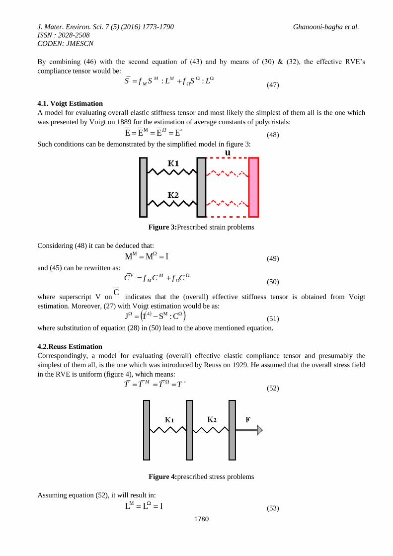
was presented by Voigt on 1889 for the estimation of average constants of polycristals: EEEE M (48)
Such conditions can be demonstrated by the simplified model in figure 3:
Figure 3:Prescribed strain problems
Considering (48) it can be deduced that:
IMMM (49)
and (45) can be rewritten as: V M
MC f C f C
(50)
where superscript V onC
indicates that the (overall) effective stiffness tensor is obtained from Voigt
estimation. Moreover, (27) with Voigt estimation would be as: C:S1J M4
(51)
where substitution of equation (28) in (50) lead to the above mentioned equation.
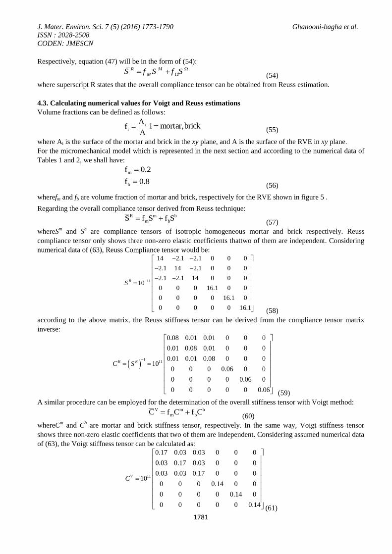
4.2.Reuss Estimation
Correspondingly, a model for evaluating (overall) effective elastic compliance tensor and presumably the
simplest of them all, is the one which was introduced by Reuss on 1929. He assumed that the overall stress field
in the RVE is uniform (figure 4), which means: MT T T T
(52)
Figure 4:prescribed stress problems
Assuming equation (52), it will result in:
ILLM (53)
J. Mater. Environ. Sci. 7 (5) (2016) 1773-1790 Ghanooni-bagha et al.
ISSN : 2028-2508
CODEN: JMESCN
1781
Respectively, equation (47) will be in the form of (54): R M
MS f S f S
(54)
where superscript R states that the overall compliance tensor can be obtained from Reuss estimation.
4.3. Calculating numerical values for Voigt and Reuss estimations
Volume fractions can be defined as follows:
A
Af i
i brick,mortari (55)
where Ai is the surface of the mortar and brick in the xy plane, and A is the surface of the RVE in xy plane.
For the micromechanical model which is represented in the next section and according to the numerical data of
Tables 1 and 2, we shall have:
8.0f
2.0f
b
m
(56)
wherefm and fb are volume fraction of mortar and brick, respectively for the RVE shown in figure 5 .
Regarding the overall compliance tensor derived from Reuss technique: b
b
m
m
R SfSfS (57)
whereSm and S
b are compliance tensors of isotropic homogeneous mortar and brick respectively. Reuss
compliance tensor only shows three non-zero elastic coefficients thattwo of them are independent. Considering
numerical data of (63), Reuss Compliance tensor would be:
11
14 2.1 2.1 0 0 0
2.1 14 2.1 0 0 0
2.1 2.1 14 0 0 010
0 0 0 16.1 0 0
0 0 0 0 16.1 0
0 0 0 0 0 16.1
RS
(58)
according to the above matrix, the Reuss stiffness tensor can be derived from the compliance tensor matrix
inverse:
1
11
0.08 0.01 0.01 0 0 0
0.01 0.08 0.01 0 0 0
0.01 0.01 0.08 0 0 010
0 0 0 0.06 0 0
0 0 0 0 0.06 0
0 0 0 0 0 0.06
R RC S
(59)
A similar procedure can be employed for the determination of the overall stiffness tensor with Voigt method: b
b
m
m
V CfCfC (60)
whereCm and C
b are mortar and brick stiffness tensor, respectively. In the same way, Voigt stiffness tensor
shows three non-zero elastic coefficients that two of them are independent. Considering assumed numerical data
of (63), the Voigt stiffness tensor can be calculated as:
11
0.17 0.03 0.03 0 0 0
0.03 0.17 0.03 0 0 0
0.03 0.03 0.17 0 0 010
0 0 0 0.14 0 0
0 0 0 0 0.14 0
0 0 0 0 0 0.14
VC
(61)
J. Mater. Environ. Sci. 7 (5) (2016) 1773-1790 Ghanooni-bagha et al.
ISSN : 2028-2508
CODEN: JMESCN
1782
Accordingly the compliance tensor can be obtained:
1
11
6.21 0.93 0.93 0 0 0
0.93 6.21 0.93 0 0 0
0.93 0.93 6.21 0 0 010
0 0 0 7.14 0 0
0 0 0 0 7.14 0
0 0 0 0 0 7.14
V VS C
(62)
The same matrix can be derived from finite element analysis results which have been performed with Ansys 11,
then compare to the results of this section. In the upcoming section, the details of the model and the procedure
of drawing stiffness matrix from analysis results will be explained.
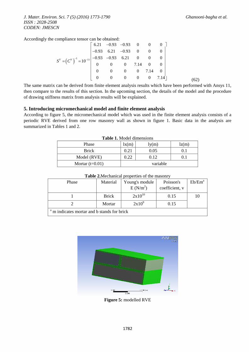
5. Introducing micromechanical model and finite element analysis
According to figure 5, the micromechanical model which was used in the finite element analysis consists of a
periodic RVE derived from one row masonry wall as shown in figure 1. Basic data in the analysis are
summarized in Tables 1 and 2.
Table 1. Model dimensions
Phase lx(m) ly(m) lz(m)
Brick 0.21 0.05 0.1
Model (RVE) 0.22 0.12 0.1
Mortar (t=0.01) variable
Table 2.Mechanical properties of the masonry
Phase Material Young's module
E (N/m2)
Poisson's
coefficient, v
Eb/Ema
1 Brick 2x10¹⁰
0.15 10
2 Mortar 2x10⁹ 0.15
a m indicates mortar and b stands for brick
Figure 5: modelled RVE
J. Mater. Environ. Sci. 7 (5) (2016) 1773-1790 Ghanooni-bagha et al.
ISSN : 2028-2508
CODEN: JMESCN
1783
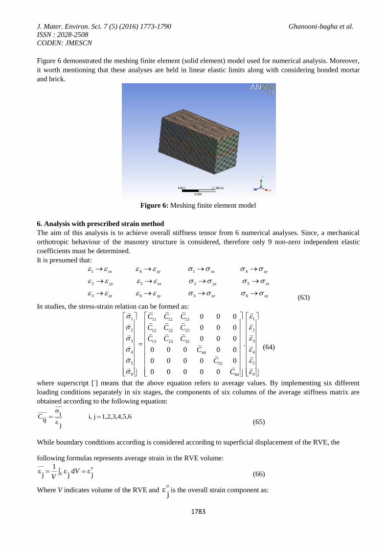
Figure 6 demonstrated the meshing finite element (solid element) model used for numerical analysis. Moreover,
it worth mentioning that these analyses are held in linear elastic limits along with considering bonded mortar
and brick.
Figure 6: Meshing finite element model
6. Analysis with prescribed strain method
The aim of this analysis is to achieve overall stiffness tensor from 6 numerical analyses. Since, a mechanical
orthotropic behaviour of the masonry structure is considered, therefore only 9 non-zero independent elastic
coefficients must be determined.
It is presumed that:
1 4 1 4
2 5 2 5
3 6 3 6
xx zy xx zy
yy zx yy zx
zz xy zz xy
(63)
In studies, the stress-strain relation can be formed as:
1 111 12 13
2 212 22 23
3 313 23 33
4 444
5 555
6 666
0 0 0
0 0 0
0 0 0.
0 0 0 0 0
0 0 0 0 0
0 0 0 0 0
C C C
C C C
C C C
C
C
C
(64)
where superscript [-] means that the above equation refers to average values. By implementing six different
loading conditions separately in six stages, the components of six columns of the average stiffness matrix are
obtained according to the following equation:
61,2,3,4,5,ji,
jε
iσ
ijC
(65)
While boundary conditions according is considered according to superficial displacement of the RVE, the
following formulas represents average strain in the RVE volume:
1ε ε d ε
j j jVV
V
(66)
Where V indicates volume of the RVE and j
ε is the overall strain component as:

J. Mater. Environ. Sci. 7 (5) (2016) 1773-1790 Ghanooni-bagha et al.
ISSN : 2028-2508
CODEN: JMESCN
1784
ε .x=u (67)
Where u is the prescribed superficial displacement. In order to obtain homogeneous stiffness tensor, the average
strain in the RVE volume is calculated from:
n
r n
r
j
jj1
)(
(68)
Where n is the number of overall RVE components that in thisstudy it was 211120. In addition,
)(r
jis the
average of jth strain component for one sample element. Then, the average stress is calculated:
n
n
r
ri
i
1
)(
(69)
Where
r
i
is the average value of ith stress component of the sample element. Therefore, the characteristics of
homogenized unit is obtainable from (65). As follows, the coefficients computed for the homogenized stiffness
tensor for 6 different loading conditions is presented:
6 61 211 21
1 1
6331 41 51 61
1
0.13 10 0.013 10
0.02 10 0
C C
C C C C
(70)
Other components can be acquired similarly, therefore the homogeneous stiffness tensor would be as:
0.13 0.013 0.02 0 0 0
0.013 0.08 0.014 0 0 0
0.02 0.014 0.18 0 0 06100 0 0 0.07 0 0
. .0 0 0 0 0.11 0
0 0 0 0 0 0.06
CF E M
(71)
Comparing C11, C22, C33, it is observed that C33 has the most value because of the parallel action of mortar and
brick in this situation. It means that when the stress or strain loading is prescribed in Z direction masonry stuff
acts in parallel. Value of C11 is less than C33 which is for the reason that mortar and brick components act both
in parallel and in series in this situation but for C22as another surface exists that the force is transferred from the
weak mortar component it is even lesser than C11.
Comparing C44, C55, C66 it is perceived that C44 is approximately equal to C66but the amount of C55 is
considerably more than the other two. This is because of the parallel behaviour of mortar and brick under shear
stress xy which indicates that the average stiffness tensor component compared to brick behaviour (stiffness
component) is influenced further. Additionally, for more analysis on outside the surface case, regarding the low
amount of C22 and C66 ( C22< C11, C66< C55), it can be observed that the likelihood of a walls' collapse because
of its extensive height is more probable than the collapse due to the extended length. Besides, low value of C66
must not be disregarded which itself may cause a sliding collapse of the wall. As a matter of fact, in order to
J. Mater. Environ. Sci. 7 (5) (2016) 1773-1790 Ghanooni-bagha et al.
ISSN : 2028-2508
CODEN: JMESCN
1785
illustrate a more complete and precise homogenized model, the significance of mortar role in determining some
of the average stiffness matrix components should be taken into mind along with the volume combination of the
two components and the elasticity coefficients fractions.
7. The proposed method
In order to obtain the homogenized stiffness matrix in homogenizing methods and in the proposed model,
according to the presented formulas in the paper, the simulation mode of MATLAB software is employed.
The suggested method is based upon Voigt and Reusstechniques;in fact it is a combination of those methods
amended by implementing coefficients to high elastic fractions of brick to mortar. Both Voigt and Reuss
techniques are simple homogenizing methods that give out the homogeneous stiffness matrix for the masonry
structure plane in the form of brick and mortar elastic stiffness. Both methods consider volume fractions of each
in the derived RVE but the difference is that the Voigt method considers the parallel masonry while in Reuss
technique masonry is presumed as series in all directions. However, regarding masonry arrangement it can be
observed that masonry is not fully parallel or in series completely. Therefore, in order to obtain homogeneous
stiffness matrix which depicts the best relation form of average volume stress in RVE with average strains, more
accurate values can be acquired in this area. The difference is that the Voigt method considers the parallel
masonry but in Reuss technique masonry is presumed as series in all directions. However, regarding masonry
arrangement it can be observed that masonry is not fully parallel or in series completely. Therefore, in order to
obtain homogeneous stiffness matrix which depicts the best relation form of average volume stress in RVE with
average strains, more accurate values can be acquired in this area.
In the proposed model, some coefficients are defined for each component of the stiffness matrix. Using these
coefficients the contribution amount of each corresponding matrix component calculated from Voigt and Reuss
approach is estimated. Meanwhile, a novel formulation combined from Voigt and Reuss methods is presented.
More explanations about determination and implementation of coefficients will be mentioned subsequently.
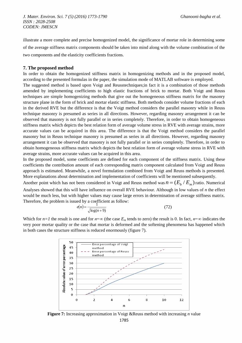
Another point which has not been considered in Voigt and Reuss method was )/( mb EEn ratio. Numerical
Analyses showed that this will have influence on overall RVE behaviour. Although in low values of n the effect
would be much less, but with higher values may cause large errors in determination of average stiffness matrix.
Therefore, the problem is issued by a coefficient as follow:
)9log(
1
nne (72)
Which for n=1 the result is one and for n=∞ (the case Em tends to zero) the result is 0. In fact, n=∞ indicates the
very poor mortar quality or the case that mortar is deformed and the softening phenomena has happened which
in both cases the structure stiffness is reduced enormously (figure 7).
Figure 7: Increasing approximation in Voigt &Reuss method with increasing n value
J. Mater. Environ. Sci. 7 (5) (2016) 1773-1790 Ghanooni-bagha et al.
ISSN : 2028-2508
CODEN: JMESCN
1786
In conclusion, the final equation for the average stiffness matrix of masonry plane in one point (RVE) is
proposed in the following form. It will relate stresses and strains of that point (average stress and strain in the
RVE is assumed as the point's stress and strain):
]..[)9log(
1 VR
RV CVCRn
C
(73)
Where R and V are in the same format as R
C andV
C , and their corresponding components are multiplied to
each other.
7.1. Determination of Effective Coefficients R and V
R matrix is assumed as:
( ) ( ) 0 0 0
( ) 0 0 0
0 0 0
0 0
0
x x y x z
y z y
z
zy
xz
xy
R R R R R
R R R
RR
sym R
R
R
(74)
Components of the matrix are defined as follows:
Ri: Ratio of total volume of mortar joints within the RVE that their largest surface is perpendicular to
displacement in i direction, to overall mortar volume (in other words ratio of total common surfaces
perpendicular to displacement in i direction to overall common surface between brick and mortar).
Rij: Ratio of total volumes of mortar joints in the RVE that their largest surface is perpendicular to one of i,j
directions, to overall mortar volume (ratio of total common surfaces perpendicular to one of i,j directions, to
total common surfaces between brick and mortar).
V matrix has the same form as R matrix that its corresponding non-zero components are calculated from: jiji RV ,, 1 (75)
Therefore, with R & V matrices RVC is obtainable from (73) for different values of n.
Because of less mortar diameter comparing to other dimensions, one surface of each mortar segments in the
RVE has larger area than other surfaces and concurringly this is the common surface between brick and mortar.
It is assumed that while the surface is perpendicular to displacement direction for determination of stiffness
matrix, mortar and brick act in series and inversely while it is parallel to displacement direction, mortar and
brick act in parallel too.
7.2. Numerical Results
The proposed formula for calculation of average stiffness matrix is represented as:
VR
RV CVCRn
C ..9log
1
(76)
WhereRC and
VC are calculated for the RVE depicted in Figure 8. Now, R & V matrices should be found then
is multiplied to the coefficients. The multiplying method is in a way that each jiR , components are multiplied
to the corresponding components jiRC , , the same procedure is true for jiV , and ji
VC , .
J. Mater. Environ. Sci. 7 (5) (2016) 1773-1790 Ghanooni-bagha et al.
ISSN : 2028-2508
CODEN: JMESCN
1787
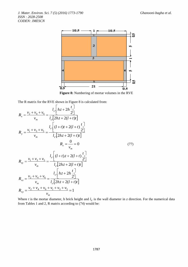
Figure 8: Numbering of mortar volumes in the RVE
The R matrix for the RVE shown in Figure 8 is calculated from:
ttlthl
ththl
v
vvvR
z
z
m
x)(2.2.
22..
642
ttlthl
ttlttll
v
vvvR
z
z
m
y)(2.2.
2)(2)(.
531
00
m
zv
R (77)
ttlthl
ttlttll
v
vvvR
z
z
m
zy)(2.2.
2)(2).(.
531
ttlthl
ththl
v
vvvR
z
z
m
xz)(2.2.
22..
642
1531642
m
xyv
vvvvvvR
Where t is the mortar diameter, h brick height and 𝑙𝑧 is the wall diameter in z direction. For the numerical data
from Tables 1 and 2, R matrix according to (74) would be:
J. Mater. Environ. Sci. 7 (5) (2016) 1773-1790 Ghanooni-bagha et al.
ISSN : 2028-2508
CODEN: JMESCN
1788
10 101 0 0 0
54 54
44 440 0 0
54 54
0 0 0 0
440 0
54
100
54
1
R
sym
(78)
And according to (75), the non-zero V matrix components would be:
44 440 0 0 0
54 54
10 100 0 0
54 54
1 0 0 0
100 0
54
440
54
0
V
sym
(79)
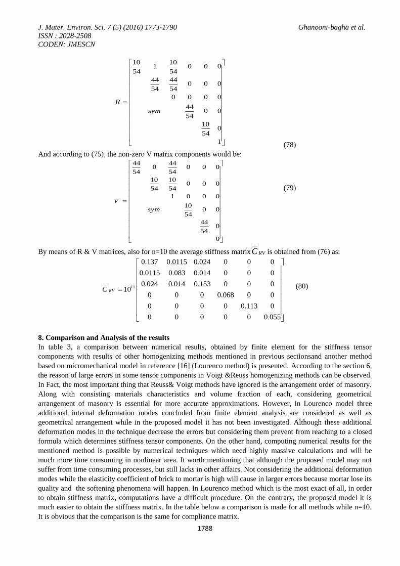
By means of R & V matrices, also for n=10 the average stiffness matrix RVC is obtained from (76) as:
11
0.137 0.0115 0.024 0 0 0
0.0115 0.083 0.014 0 0 0
0.024 0.014 0.153 0 0 010
0 0 0 0.068 0 0
0 0 0 0 0.113 0
0 0 0 0 0 0.055
RVC
(80)
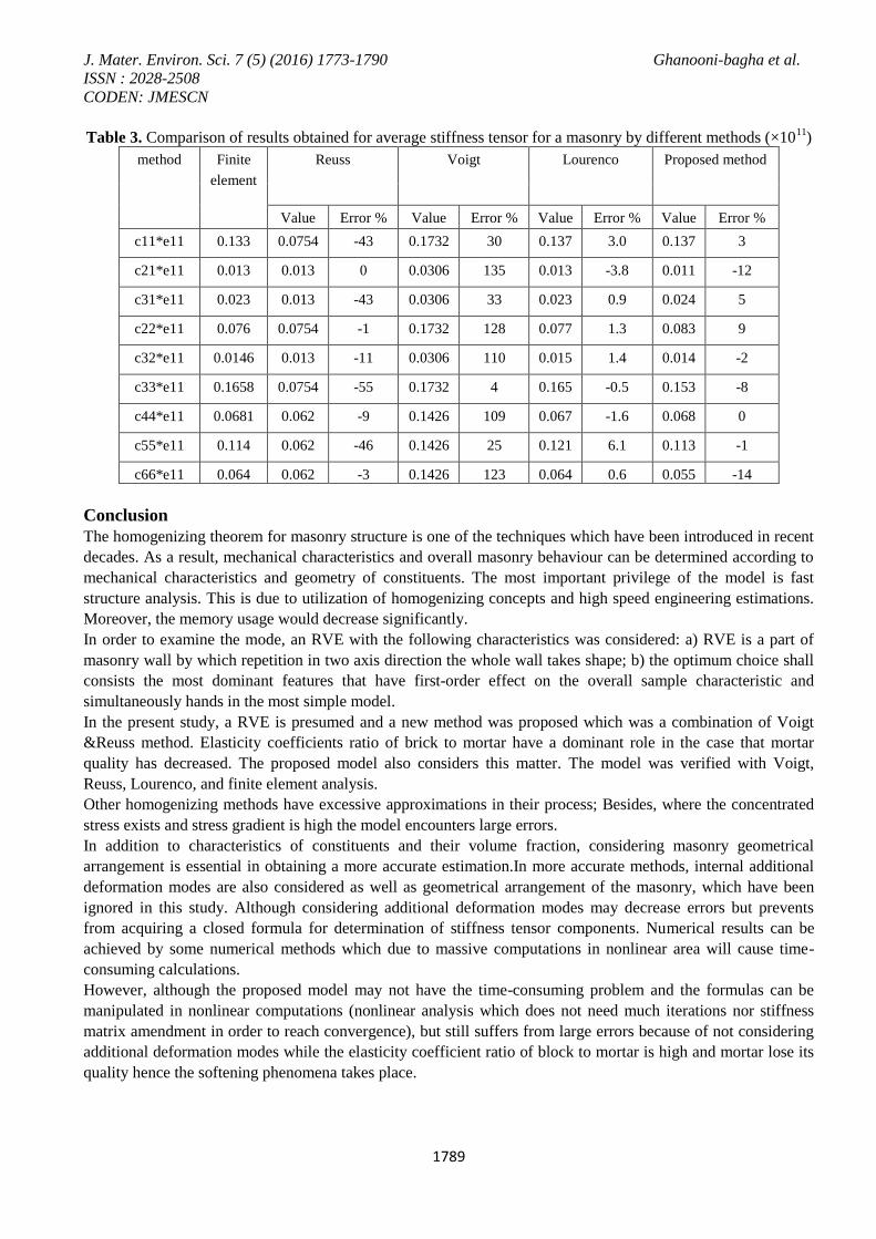
8. Comparison and Analysis of the results
In table 3, a comparison between numerical results, obtained by finite element for the stiffness tensor
components with results of other homogenizing methods mentioned in previous sectionsand another method
based on micromechanical model in reference [16] (Lourenco method) is presented. According to the section 6,
the reason of large errors in some tensor components in Voigt &Reuss homogenizing methods can be observed.
In Fact, the most important thing that Reuss& Voigt methods have ignored is the arrangement order of masonry.
Along with consisting materials characteristics and volume fraction of each, considering geometrical
arrangement of masonry is essential for more accurate approximations. However, in Lourenco model three
additional internal deformation modes concluded from finite element analysis are considered as well as
geometrical arrangement while in the proposed model it has not been investigated. Although these additional
deformation modes in the technique decrease the errors but considering them prevent from reaching to a closed
formula which determines stiffness tensor components. On the other hand, computing numerical results for the
mentioned method is possible by numerical techniques which need highly massive calculations and will be
much more time consuming in nonlinear area. It worth mentioning that although the proposed model may not
suffer from time consuming processes, but still lacks in other affairs. Not considering the additional deformation
modes while the elasticity coefficient of brick to mortar is high will cause in larger errors because mortar lose its
quality and the softening phenomena will happen. In Lourenco method which is the most exact of all, in order
to obtain stiffness matrix, computations have a difficult procedure. On the contrary, the proposed model it is
much easier to obtain the stiffness matrix. In the table below a comparison is made for all methods while n=10.
It is obvious that the comparison is the same for compliance matrix.
J. Mater. Environ. Sci. 7 (5) (2016) 1773-1790 Ghanooni-bagha et al.
ISSN : 2028-2508
CODEN: JMESCN
1789
Table 3. Comparison of results obtained for average stiffness tensor for a masonry by different methods (×1011
)
method Finite
element
Reuss Voigt Lourenco Proposed method
Value Error % Value Error % Value Error % Value Error %
c11*e11 0.133 0.0754 -43 0.1732 30 0.137 3.0 0.137 3
c21*e11 0.013 0.013 0 0.0306 135 0.013 -3.8 0.011 -12
c31*e11 0.023 0.013 -43 0.0306 33 0.023 0.9 0.024 5
c22*e11 0.076 0.0754 -1 0.1732 128 0.077 1.3 0.083 9
c32*e11 0.0146 0.013 -11 0.0306 110 0.015 1.4 0.014 -2
c33*e11 0.1658 0.0754 -55 0.1732 4 0.165 -0.5 0.153 -8
c44*e11 0.0681 0.062 -9 0.1426 109 0.067 -1.6 0.068 0
c55*e11 0.114 0.062 -46 0.1426 25 0.121 6.1 0.113 -1
c66*e11 0.064 0.062 -3 0.1426 123 0.064 0.6 0.055 -14
Conclusion
The homogenizing theorem for masonry structure is one of the techniques which have been introduced in recent
decades. As a result, mechanical characteristics and overall masonry behaviour can be determined according to
mechanical characteristics and geometry of constituents. The most important privilege of the model is fast
structure analysis. This is due to utilization of homogenizing concepts and high speed engineering estimations.
Moreover, the memory usage would decrease significantly.
In order to examine the mode, an RVE with the following characteristics was considered: a) RVE is a part of
masonry wall by which repetition in two axis direction the whole wall takes shape; b) the optimum choice shall
consists the most dominant features that have first-order effect on the overall sample characteristic and
simultaneously hands in the most simple model.
In the present study, a RVE is presumed and a new method was proposed which was a combination of Voigt
&Reuss method. Elasticity coefficients ratio of brick to mortar have a dominant role in the case that mortar
quality has decreased. The proposed model also considers this matter. The model was verified with Voigt,
Reuss, Lourenco, and finite element analysis.
Other homogenizing methods have excessive approximations in their process; Besides, where the concentrated
stress exists and stress gradient is high the model encounters large errors.
In addition to characteristics of constituents and their volume fraction, considering masonry geometrical
arrangement is essential in obtaining a more accurate estimation.In more accurate methods, internal additional
deformation modes are also considered as well as geometrical arrangement of the masonry, which have been
ignored in this study. Although considering additional deformation modes may decrease errors but prevents
from acquiring a closed formula for determination of stiffness tensor components. Numerical results can be
achieved by some numerical methods which due to massive computations in nonlinear area will cause time-
consuming calculations.
However, although the proposed model may not have the time-consuming problem and the formulas can be
manipulated in nonlinear computations (nonlinear analysis which does not need much iterations nor stiffness
matrix amendment in order to reach convergence), but still suffers from large errors because of not considering
additional deformation modes while the elasticity coefficient ratio of block to mortar is high and mortar lose its
quality hence the softening phenomena takes place.
J. Mater. Environ. Sci. 7 (5) (2016) 1773-1790 Ghanooni-bagha et al.
ISSN : 2028-2508
CODEN: JMESCN
1790
References
1. Mistler M., Anthoine A., Butenweg C., Comp.Struc., 85 (2007) 1321. 2. Anthoine A., I.J.S.S., 32 (1995) 137.
3. Lourenço P.B., Zucchini A., Comput. Struct., 85 (2007) 193.
4. Karam S., Mecanique 331 (2003) 641.
5. Mistler M., Anthoine A., Butenweg C., Comp. Struc. 85 (2007) 1321.
6. MistlerM., ButenwegC., AnthoineA., Proceed. 7th Inter. Con.Com.Struc.Techn.,Civil-Comp Press,
Scotland (2004).
7. Giordano A., MeleE., De Luca A., Eng. Struc., 24 (2002) 1057.
8. CavalagliN., CluniF., GusellaV., Intel. J.Sld. Struc., 50 (2013) 4226.
9. Nunziante L., Fraldi M., Rivieccio P.G., Chapter Ш– Mech.Mas.Struc., (2005).
10. Sacco E., Europ. J. Mech. A/Sld., 28 (2008) 202.
11. Wei X., Hao H., Intel. J. Imp. Eng., 36 (2009) 522.
12. Mahmoodi-k M., Davoodabadi I., Višnjić V., Afkar A., Tech. Gazette, 21 (2014) 3.
13. Nasser S. N., Hori M., Micromechanics: Second Edition, North-Holland, Amsterdam (1993).
14. Zhao C., Mühlhaus H.B., Hobbs B.E., Int. J. Num. Anal. Meth. Geomech., 21 (1997) 863.
15. Bakeer T., Eng. Struc., 1 (2016) 20.
16. Zucchini A., Lourenco P.B., Intel. J. Sld. Struc., 39 (2002) 3332.
17. Rivieccio P.G., PhD. Thesis, University of Napoli Federico (2005).
18. Hill R., J. Mech. Phys. Solids, 13 (1965) 213.
(2016) ; http://www.jmaterenvironsci.com/