Embed Size (px)
Citation preview

Automotive Product Information API 14
Detent Pinsfor Automotive Transmissions

3
Page
Detent pinsFunction and types
4 Functions of detent pins4 Types and applications
Design5 Design features6 Types
Gearshift force curve7 Stroke characteristics 8 Displacement resistance – dependent on the type of detent pin9 Displacement resistance – dependent on the mounting position of the detent pin
10 Travel characteristicsSpring preload force
11 Detent pin with adjustable spring preload forceSealing
12 Sealing compounds13 Support washers13 Special sealing edges13 Press fit
Design of adjacent componentsFitting and dismantling of detent pins
14 Design of adjacent components14 Fitting of detent pins15 Dismantling of detent pins
Tightening torque16 Tightening torque for threaded bodies
Anti-corrosion protection17 Corrotect® plating17 Phosphating17 Zinc plating and chromating17 Corrosion-resistant material
Ramp profile18 Contour of the ramp profile
Load conditions19 Force conditions – effective and resultant forces
Test methods20 Test conditions and focus of tests24 Running marks25 Summary26 Checklist27 Dimension list29 Reference list
Contents

4
Function and types
Detent pins are used in gearshift systems in gearboxes. In the external gearshift system, they are normally located beneath the passenger compartment. In the internal gearshift system, they are pressed into or screw mounted in the gearbox housing or are part of lever mechanisms in the gearbox. They act on movable parts such as the input selector shaft, selector rods or selector rails. Due to their design and functions specially matched to the application, they have a decisive influence in the manual automotive gearbox on the technically optimum gearshift behaviour and the gearshift feel experienced by the driver.
Functions of detent pinsThe detent pins fulfil primary and secondary tasks.The primary functions are:■ location and positioning of the required gearshift position;■ locking in place once the gearshift position has been
located;■ ensuring precise and secure gearshift by means of a defined
gearshift resistance;■ communicating a positive gearshift feel to the driver and a
clear sensation that the gear has been engaged.
The secondary functions are:■ guiding interlocking parts:
– simultaneously locking out components not directly involved in the gearshift operation and locking in place the selected gear,
– securing components not directly involved in the gearshift operation to prevent uncontrolled, independent movement;
■ guiding gates:– allowing precise movement of the mechanical linkages;
■ acting as carrier components to support electrical switches:– closing the switch contacts in integrated switch
components.
Types and applications – Figure 1In the left of the figure, types for more demanding applications are shown – the gearshift operation is controlled by linear and swivel motion. On the right, simpler types are shown – they represent applications for selector rods and rails that only perform linear motion.
and detent pins ARRE, e.g. for selector shafts Detent bush ARR and detent pins ARRE, e.g. for selector rods.
Figure 1 · Detent pin – types and application
1 2
3
4 5
1
1
2
3
4
5
Detent element Detent element
Selector shaft
Selector rodSelector finger
Locking plate 4
014
052
5
Design
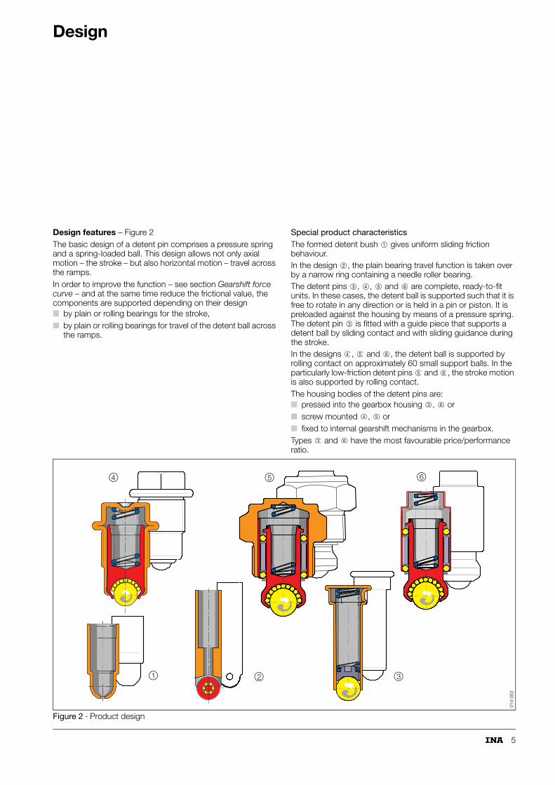
Design features – Figure 2The basic design of a detent pin comprises a pressure spring and a spring-loaded ball. This design allows not only axial motion – the stroke – but also horizontal motion – travel across the ramps.In order to improve the function – see section Gearshift force curve – and at the same time reduce the frictional value, the components are supported depending on their design■ by plain or rolling bearings for the stroke,■ by plain or rolling bearings for travel of the detent ball across
the ramps.
Special product characteristicsThe formed detent bush gives uniform sliding friction behaviour.In the design , the plain bearing travel function is taken over by a narrow ring containing a needle roller bearing. The detent pins , , and are complete, ready-to-fit units. In these cases, the detent ball is supported such that it is free to rotate in any direction or is held in a pin or piston. It is preloaded against the housing by means of a pressure spring. The detent pin is fitted with a guide piece that supports a detent ball by sliding contact and with sliding guidance during the stroke.In the designs , and , the detent ball is supported by rolling contact on approximately 60 small support balls. In the particularly low-friction detent pins and , the stroke motion is also supported by rolling contact. The housing bodies of the detent pins are:■ pressed into the gearbox housing , or■ screw mounted , or■ fixed to internal gearshift mechanisms in the gearbox.Types and have the most favourable price/performance ratio.
Figure 2 · Product design
1
2
3 4 5 6
3
4 5 6
5 6
3 6
4 5
3 6
4
1 2 3
5 6
014
053

6
Design
Types – Figure 3The objectives in optimising detent pins include reducing the frictional value. In this way, the gearshift forces required to roll over the ramp profile of a selector shaft can be significantly reduced.The magnitude of the frictional value is influenced by■ the ramp geometry.■ the type of detent pin.Figure 3 shows the relationship between the spring preload force FF and the gearshift force required FS for various types. The angle of the ramp geometry – at the reference point of the spring force – is between 38° and 42°.
Even the type without support balls behind the detent ball reduces the gearshift force by 40%. The movable detent ball and the stroke motion of the plunger give significantly improved frictional value behaviour in comparison with the rigid design. The frictional value is also influenced by the bearing arrangement or type of bearing arrangement of the plunger and detent ball. In order to further reduce the frictional value, the detent ball was therefore also supported by rolling contact in the design .The lowest frictional value occurs in the design . In this case, the detent ball and the plunger for stroke motion are supported by rolling contact.
Figure 3 · Types
2
3
4
0,55
0,71
0,846
0,932
0,85
1,0
1,18
1,0
1,2
1,1
1,0
0,9
0,8
0,7
0,6
0,5
0,4
F
FS
F
40˚
F
FF
S
1 2 3 4
014
054

7
Gearshift force curve
The type and position of the detent pin have a decisive influence on the force curve occurring during the gearshift operation. In order to determine the necessary design measures for the detent pins, the following aspects of the overall gearshift curve are considered:■ the stroke characteristics
– displacement of the plunger in the housing body■ the displacement resistance
– dependent on the type of detent pin– dependent on the mounting position of the detent pin
■ travel characteristics– travel of the detent ball/plunger across a ramp.
Stroke characteristics – Figure 4Various detent pins in volume production are compared with each other on a test rig – see section Test methods. The diameter of the detent balls was 8,731 mm, the balls are supported by rolling contact.
The stroke motion of the plunger is supported:by plain contact in the housing,by rolling contact by means of a ball cage.
The tilting clearance of the plunger is between 0,05 mm and 0,3 mm, depending on the type of detent pin. The force is applied at less than 45°. The tilting can thus be described in approximate terms.
Interpretation of the force curveThe following are marked in the figure:■ the actual working range in the functional condition in order
to overcome the relevant ramp profile,■ the tolerance scatter occurring as a result of volume
production.The irregularities at the start of the curve result from the necessary operating clearance of the stroke motion bearing arrangement. The increase in force at the end of the hysteresis curve is caused by the impact of the plunger on the base of the housing.
Figure 4 · Stroke characteristics
1
2
0
60
80
110
150
200
1 2 3 4 5mm
N
Tole
ranc
e ra
nge
Working range
Working stroke
Dis
plac
emen
t res
ista
nce
12
134
097

8
Gearshift force curve
Displacement resistance – dependent on the type of detent pinVarious types in volume production are compared with each other on a test rig – see section Test methods.
The detent ball has a diameter of 8,731 mm. The detent pins , , , are preloaded by springs to 70 N, while the detent
pin is preloaded to 55 N.The ball is supported as follows (Figure 5):
rigidly integrated in a plain sleevesupported by sliding contact in a specially formed plastic cupsupported by sliding contact in plasticsupported by sliding contact in a cup lined with Teflon®
supported by rolling contact on approx. 60 support balls.
Interpretation of the force curveThe displacement resistance in the plain bush is up to 10 times higher than with the ball supported by rolling contact. Since mixed friction is present, the sliding friction can be reduced by up to 40%, for example in the detent pin , depending on adjustment.
Figure 5 · Displacement resistance – dependent on the type of detent pin
1 3 4 5
2
1
2
3
4
5
4
2 4 6 8 10
6
8
– 2
4
6
8
12
0
2
4
10
12
(N)
(N)
–
–
–
–
–
Displacement travel
12 14 16 18 20 mm
Dis
plac
emen
t res
ista
nce
10
12
3
4
5
134
096

9
Displacement resistance – dependent on the mounting position of the detent pinThe displacement resistance of a detent pin in the following mounting positions is measured on a test rig – see section Test methods. The detent ball is positioned (Figure 6):■ vertically downwards■ horizontally■ vertically upwards.The detent ball has a diameter of 8,731 mm. It is supported by rolling contact on approx. 60 support balls and preloaded to 55 N by a spring.The detent ball is moved across a flat surface.
Interpretation of the force curveThe displacement resistance is at its highest with the detent ball facing vertically downwards and at its lowest with the detent ball facing vertically upwards (Figure 6). The cause lies in the degree of freedom of the "chaotically" circulating support balls. In the case of the detent ball facing vertically downwards, all the support balls collect in the largest free space, i.e. just behind the retention mechanism for the ball. The free space in the centre of the pin is not sufficient, however, for ideal movement of the support balls. The balls are in contact under load and sliding friction occurs between the rolling elements. The movement conditions are optimum in the case of the detent ball located at the top. In this case:■ the support balls collect in the centre of the pin and form the
largest arc around the detent ball■ the free space for crimping of the pin is at its largest.
Figure 6 · Displacement resistance – dependent on the mounting position of the detent pin
Dis
plac
emen
t res
ista
nce
Dis
plac
emen
t res
ista
nce
Dis
plac
emen
t res
ista
nce
N N N
3
2
1
0
1
2
0 2 4 6 8 10 12 14 16 18 20 mm3
2
1
0
1
2
0 2 4 6 8 10 12 14 16 18 20 mm3
2
1
0
1
2
0 2 4 6 8 10 12 14 16 18 20 mm
Friction value � = 0,027 Friction value � = 0.018 Friction value � = 0,007
Displacement travel Displacement travel Displacement travel
014
103

10
Gearshift force curve
Travel characteristics – Figure 7Measurement conditionsOn a test rig – see section Test methods, detent pins are compared with each other that have■ different bearing arrangements for the detent ball and
plunger.The selector rod is supported in rolling bearings. The ramp profile in the selector rod was matched to the diameter – 8,731 mm – of the detent ball. The total travel during gearshift into the selected gear and back to the original position is measured.
Detent pin with components supported by sliding contactThe hysteresis of the gearshift force curve has a very wide spread. This means that it is significantly more difficult for the plunger to snap automatically into the base of the groove in the selector shaft. This is due to the high friction value, determined by the design, of the movable parts. The gearshift force resistance of 55 N to 60 N is partially induced by the friction forces, but the required difference in level to return the gearshift lever to the neutral position is thereby reduced again.
Consequences of the force curveThere is no sensation that gearshift has been achieved precisely and the gearshift operation has been securely completed. Due to the vague gearshift curve, the driver does not experience the "feel of quality".
Detent ball and plunger supported by rolling contactThe hysteresis shows a narrow-shaped gearshift force curve with a return point free from response lag. The force required to achieve the positive snap-in effect of the plunger – the large area is shown with grid lines in the diagram – was increased from 25 N for the design with sliding contact support to between 40 N and 50 N. Clear improvements were demonstrated with an increase in the diameter ratio between the detent ball and support balls.
Consequences of the force curveIn conjunction with the higher effective spring preload force precisely matched to the gearshift force curve, the detent pin with components supported by rolling contact and with reduced friction leads to the required "feel of quality". See also the section Spring preload force.
Figure 7 · Functional parts supported by sliding contact and by rolling contact – comparison
Gearshift travel
Spr
ing
forc
e [N
]
(mm) 134
278
11
Spring preload force
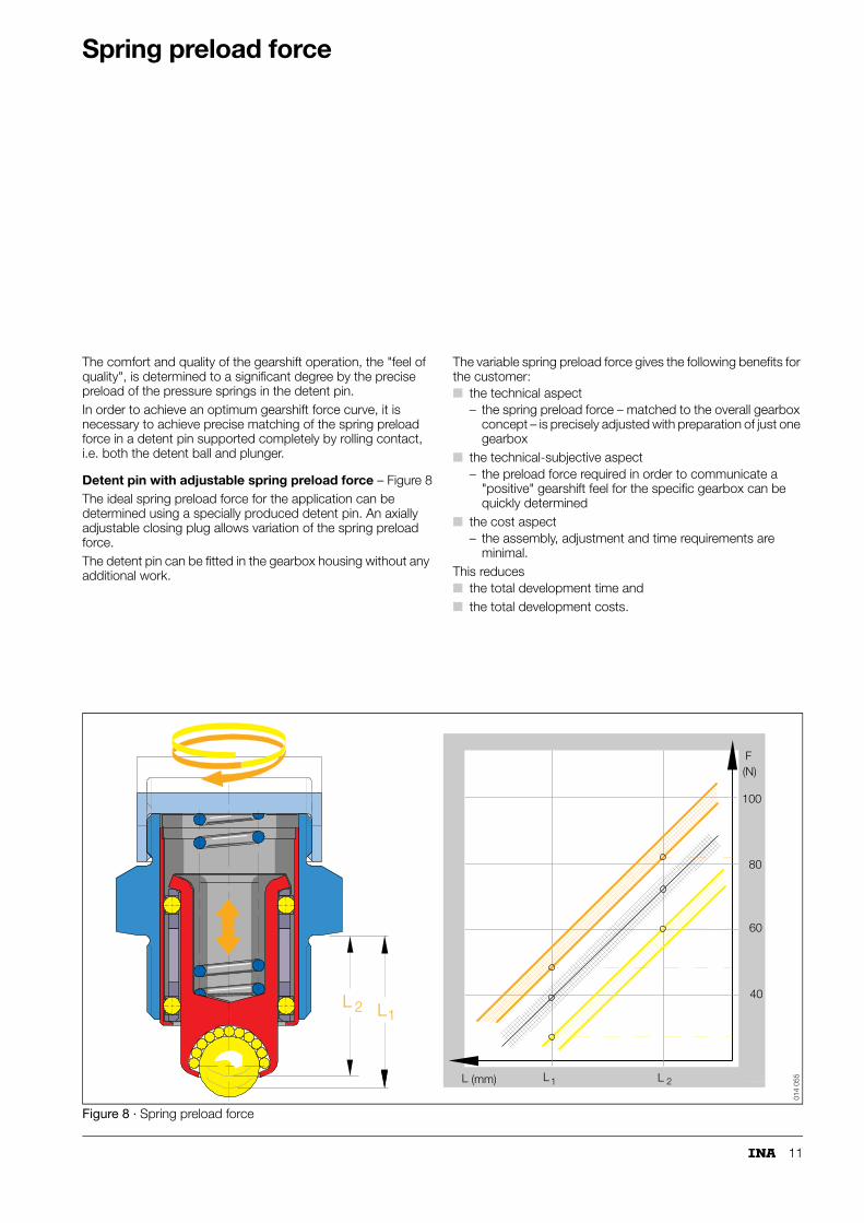
The comfort and quality of the gearshift operation, the "feel of quality", is determined to a significant degree by the precise preload of the pressure springs in the detent pin.In order to achieve an optimum gearshift force curve, it is necessary to achieve precise matching of the spring preload force in a detent pin supported completely by rolling contact, i.e. both the detent ball and plunger.
Detent pin with adjustable spring preload force – Figure 8The ideal spring preload force for the application can be determined using a specially produced detent pin. An axially adjustable closing plug allows variation of the spring preload force. The detent pin can be fitted in the gearbox housing without any additional work.
The variable spring preload force gives the following benefits for the customer: ■ the technical aspect
– the spring preload force – matched to the overall gearbox concept – is precisely adjusted with preparation of just one gearbox
■ the technical-subjective aspect– the preload force required in order to communicate a
"positive" gearshift feel for the specific gearbox can be quickly determined
■ the cost aspect– the assembly, adjustment and time requirements are
minimal. This reduces■ the total development time and■ the total development costs.
Figure 8 · Spring preload force
40
60
80
100
L1L 2
F(N)
L L1 2L (mm)
014
055

12
Sealing
If detent pins are to be fitted in the gearbox housing from outside, the must fulfil the following requirements:■ they must create an airtight seal in relation to the gearbox
housing– after assembly, gearboxes are checked for leaks by
means of compressed air;■ they must be securely seated
– detent pins with a screw fitting thread must be fitted with a defined tightening torque;
■ they must operate as corrosion-free as possible throughout their operating life– where detent pins are located on the outside of the
gearbox, the external parts of the detent pin are exposed to corrosive media.
Sealing compoundsDetent pins with a threaded body are generally provided with a sealing compound on the thread.For reasons of production technology, the coating covers two to three turns of the thread – determined by the jet width of the spray nozzles in the application device (1 mm – 2 mm) and the frequency of rotation (1 to 1,5 times).
Threaded steel body – Figure 9A micro-encapsulated, yellow adhesive (OT precote 30) or a red adhesive (Loctite) is used on threaded steel bodies.The micro-capsules are breached by the compressive and/or shear loads occurring when the detent pin is screwed in. The fluid released hardens once it comes into contact with the binder system. This gives good sealing action even though only a small quantity of sealing agent is required. The adhesive also prevents corrosion in the thread connection. The screw connection can thus be loosened again without damaging the thread and by the use of normal tools.
Aluminium threaded body – Figure 10In the case of aluminium threaded bodies, the coating OT precote 30 tends to cause fretting in the flank area. The white sealing agent OT precote 5 is therefore used.However, this film-forming dispersion containing non-reactive material requires thicker application over a larger area. The coating should therefore cover at least two to three turns of the thread.
Figure 9 · Sealing compound for steel threaded bodies
Figure 10 · Sealing compound for aluminium threaded bodies
134
207
134
208

13
Support washers – Figure 11As an alternative to sealing compounds, special support washers of various thicknesses depending on the material – steel, aluminium, pressboard – can be used. However, this type of seal has a disadvantageous effect on the additional axial tolerance. This has a negative effect on the specific spring characteristics of detent pins and leads to a further scatter in characteristic curve values.
Special sealing edges – Figure 11Special sealing edges on the locating faces of threaded bodies are a technically straightforward and economical sealing method. These detent pins can be loosened and refitted once. The full effectiveness of the sealing action depends, however, on the tightening torque and surface quality of the locating face. If they are used several times over with repeated loosening and fitting, this sealing method no longer fulfils the INA quality standard.INA has a patent for the method Special sealing edge.
Press fit – Figure 11Certain types of detent pin are not screw mounted but are simply pressed into the gearbox housing. In addition to the secure sealing action achieved by a press fit, these products can be fitted easily and cheaply.Fitting should be carried out by machine using a press-in tool. A force-dependent shut-off point should be set at approx. 8 000 N.
Figure 11 · Sealing – support washer, sealing edge, press fit
Support washer Sealing edge Press fit
014
056
14
Design of adjacent componentsFitting and dismantling of detent pins
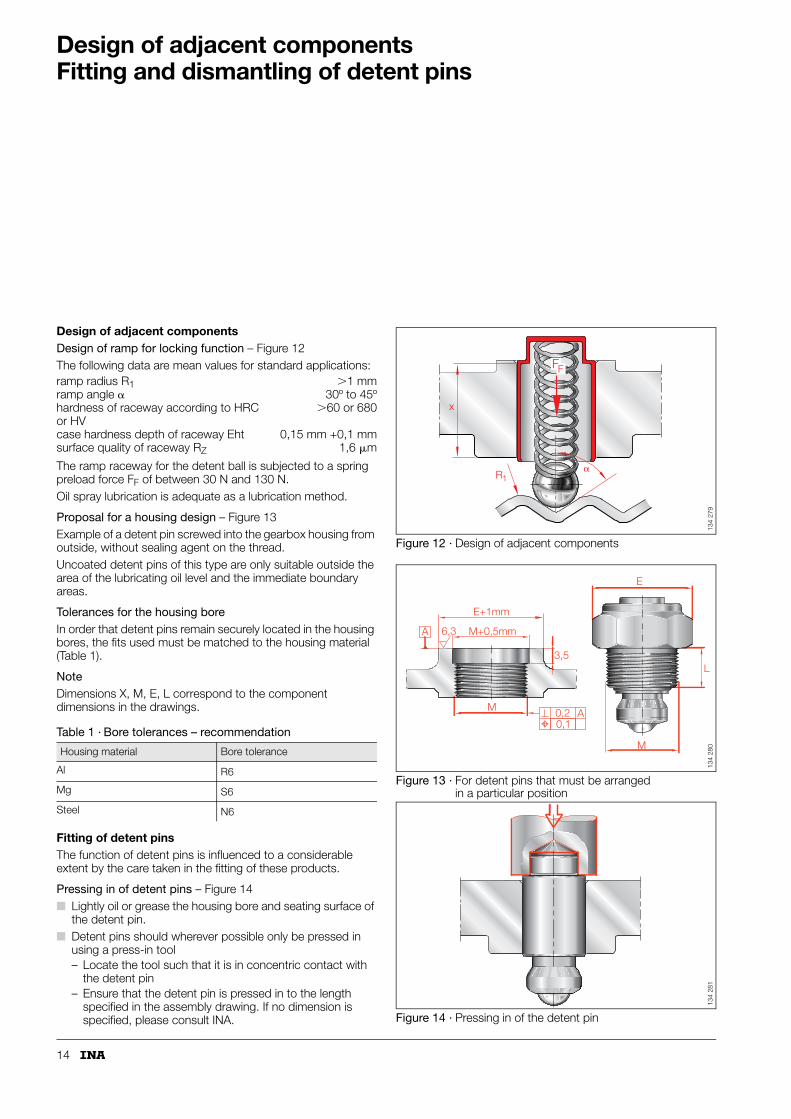
Design of adjacent componentsDesign of ramp for locking function – Figure 12The following data are mean values for standard applications:
The ramp raceway for the detent ball is subjected to a spring preload force FF of between 30 N and 130 N. Oil spray lubrication is adequate as a lubrication method.
Proposal for a housing design – Figure 13Example of a detent pin screwed into the gearbox housing from outside, without sealing agent on the thread.Uncoated detent pins of this type are only suitable outside the area of the lubricating oil level and the immediate boundary areas.
Tolerances for the housing boreIn order that detent pins remain securely located in the housing bores, the fits used must be matched to the housing material (Table 1).
NoteDimensions X, M, E, L correspond to the component dimensions in the drawings.
Fitting of detent pinsThe function of detent pins is influenced to a considerable extent by the care taken in the fitting of these products.
Pressing in of detent pins – Figure 14■ Lightly oil or grease the housing bore and seating surface of
the detent pin.■ Detent pins should wherever possible only be pressed in
using a press-in tool– Locate the tool such that it is in concentric contact with
the detent pin– Ensure that the detent pin is pressed in to the length
specified in the assembly drawing. If no dimension is specified, please consult INA.
Figure 12 · Design of adjacent components
Figure 13 · For detent pins that must be arranged in a particular position
Figure 14 · Pressing in of the detent pin
ramp radius R1 �1 mmramp angle � 30º to 45ºhardness of raceway according to HRC or HV
�60 or 680
case hardness depth of raceway Eht 0,15 mm +0,1 mmsurface quality of raceway RZ 1,6 �m
Table 1 · Bore tolerances – recommendation
Housing material Bore tolerance
Al R6
Mg S6
Steel N6
R1�
x
FF
134
279
A 6,3
E+1mm
M+0,5mm
3,5
M
0,10,2 A
E
L
M
134
280
134
281

15
Dismantling of detent pins – Figure 15Detent pins are high precision components. Their level of quality is demonstrated, for example, by the fact that there is no spare parts requirement for these products – the operating life generally exceeds, for example, the life of the gearbox. In normal circumstances, therefore, they do not need to be dismantled. However, it may be necessary to dismantle detent pins■ on automatic gearbox assembly lines using robots,■ for the separation and reintegration of materials used in the
economic process – recycling.
Depending on their external form and the design of the adjacent construction, the detent pins are either
pressed throughor removed using an extraction tool by means of
an appropriately shaped base profile of the formed housing, a circumferential collar on the housing, a formed recess on the housing seat.
Figure 15 · Dismantling of detent pins
1
2
3
4
1 2 3
134
098

16
Tightening torque
Tightening torque for threaded bodiesDetent pins with a threaded body should be located in the gearbox housing with a defined tightening torque – for measurement values for tear-off torques see Figure 16.Plastic threaded bodies – in some cases reinforced with a steel corset – are not currently used in volume production.
Measurement conditionsThe values were determined:■ on thin-walled threaded bodies of identical geometry and
dimensions – made from different materials■ with "technically dry" threaded flanks.
Changes in the friction valueIf the parts are oiled (e.g. with gearbox oil), or plated (e.g. with sealing agent oil), friction is reduced. The measurement values are then up to 50% lower than in the "technically dry" version.Coated threaded bodies – e.g. with Corrotect® – show slightly higher tear-off torques.
Figure 16 · Tear-off torques of threaded bodies
0
20
40
60
80
100
120
140
A/F 24
16
14
A/F 24
16
M20×1,5
11
M18×1,5
Threaded body AThreaded body B
C45
16 M
n C
r 5
9 S
Mn
28
9 S
Mn2
8
Al a
lloy
PA66
–GF3
5/H
**
PA66
–LG
F40
*
PA66
–LGF
40
PA66
–GF2
5
PA66
–GF3
5/H
*
121620
24
33
80
100
80
100
125
Tear
-off
torq
ue M
(N
m)
60
Al a
lloy
d
** With injection moulded steel sleeve* Injection moulded steel sleeve with specially treated surface
014
063

17
Anti-corrosion protection
Depending on the design principle of the gearbox, component parts of the detent pins may protrude from the gearbox housing. These parts are exposed to corrosion as a result of environmental influences and must be appropriately protected. The results of various anti-corrosion protection measures are shown in Figure 17. The treated parts were subjected to a salt spray mist test in accordance with DIN 50 021.
Corrotect® platingThe INA special plating Corrotect® is an extremely thin – preferably 2 �m – protective layer applied to all surfaces by electroplating methods. It gives long-term protection of detent pins – for example against the action of salt water, contaminated water and gritting salt. Due to the very thin layer, the process is also highly suitable for rolling element raceways.Under load, the layer is compacted into the surface roughness profile. Smaller bright areas remain protected against rust due to the cathodic protection effect. The coloured chromate passivation (blue, yellow or black) can be used for colour coded identification of detent pins. Yellow and black chromate passivation contains Cr(VI). Alternatively, iridescent forms of chromate passivation free from Cr(VI) are under development.
PhosphatingPhosphating offers only very limited protection. It is sufficient for mounting positions with little risk of corrosion.
Zinc plating and chromatingSince the layers are up to 20 �m thick in these cases, these process are not suitable for:■ rolling element raceways■ parts to be joined inside each other, since the layer thickness
has too pronounced an effect on the bearing operating clearance.
Corrosion-resistant materialFor certain requirements, aluminium alloys are used for the screw mounting bodies of detent pins. These:■ offer optimum protection against corrosion■ prevent stress corrosion in gearbox housings made from
aluminium alloys■ are resistant to seawater for overseas transport.Plastic is another corrosion-resistant material. INA detent pins preferably have iron/zinc platings with chromate passivation. Components with raceways are plated with Corrotect®. If parts with Fe/Zn chromate passivation are used in magnesium gearbox housings, for example, the plating must be additionally sealed using silicate. If temperatures in excess of +90 ºC are possible, please consult INA.
Figure 17 · Anti-corrosion protection for detent pins
Yello
w c
hrom
ate
pas
siva
tion
Bla
ck c
hrom
ate
pas
siva
tion
Anti-corrosion protection (h)
Coating thickness (�m)
Phosphateddepending onpreservative
Fe/Zn + chromating to DIN 50 962 without thermal load ( = bis 90 ˚C )
Corrotect Fe/Zn chromating to DIN 50 962
additional silicate sealing
DeltaTone
Blu
e ch
rom
ate
pas
siva
tion
Coating of detent pins
0
50
100
150
200
250
Corrotect is atrademark ofINA-Schaeffler KGregistered in Germany
®®
®
162
168

18
Ramp profile
Products involved in selecting and engaging gears must have the technically correct "optimum gearshift curve" and communicate this clearly and reliably to the driver. This is achieved by means including■ support of the gearshift elements by means of rolling
bearings,■ a generally smooth and low-friction curve for the operations
of selecting, engaging and securing gears■ the precisely defined preload force of the spring elements in
the detent pins.However, the design of the adjacent parts can also have a detrimental effect on the selection and engagement process. Whether the driver assesses the gearshift operation as positive or negative will depend, for example, on■ the design of the contact zone between the selector rod or
selector shaft and the detent ball – the ramp profile.
Contour of the ramp profileIf the ramp contour is not geometrically matched to the detent ball, the gearshift forces and torques will have a noticeably unfavourable effect on the gearshift feel and the driver.
Ramp contour, version 1 – Figure 18If the contour of the ramp profile is not matched to the detent ball, the torque curve will be of this form. Even with slight motion of the selector rod, the torque curve increases further; i.e. the force required only decreases when the detent ball reaches the cusp point in the ramp contour. No "positive gearshift feel" can therefore be expected.
Ramp contour, version 2 – Figure 18The torque curve is significantly more precise and uniform. This optimised curve is achieved by changing the position of the contact point between the detent bal and locking groove. This is now at the transition from the groove tangent to the radius shoulder. For optimum results, however, this point must not deviate from the theoretically ideal value by more than �10°.The modified contour gives the following improvements:■ significantly smaller running marks in the contact zones, ■ uniform efficiency, ■ longer operating life, ■ a gearshift curve that gives the optimum gearshift feel.
Figure 18 · Torque curve of various ramp contours
00
11
1 1
00
11
1 1
Gearshift travel
Gea
rshi
ft fo
rce
Gearshift travel
Gea
rshi
ft fo
rce
Ramp contour, version 1 Ramp contour, version 2
2
31 5
4 6
R
N
1 2 3 1 2 3
1
2
3
1
2
3
014
061

19
Load conditions
In order to determine the correct size of detent pin, the loads occurring must be taken into consideration.
Force conditions – effective and resultant forcesDetent pins are used under predominantly static load. The significant factors for determining the bearing load are therefore the distance a from the loading point and the supporting/base width b of the bearing arrangement (Figure 19). Since the force is applied outside the support base b (typical for detent pins), the force is not supported favourably. When the selector rod is activated, the external forces act on the detent pin (Figure 20). Due to the rolling motion of the detent ball, the distance a from the loading point continues to decrease. At the same time, the active force increases in accordance with the spring rate of the detent pin. The following must therefore be taken into consideration in the design of the detent pin: ■ the minimum gearshift force FS, the coefficient of friction �
and the bearing load FA (formulae 1 to 3).
FF NSpring preload force
FS NMinimum gearshift force
FA NBearing load at support point A
FB NBearing load at support point B
a mmDistance between detent ball and row of support balls A
b mmDistance between support ball row A nd B
FR NFriction force (FR = FN · �)
FN NNormal force component
� ºFriction angle
�, � ºRamp angle relative to initial basis (� = 90º – �)
� –Coefficient of friction.
Figure 19 · Forces acting on detent pin
Figure 20 · Forces acting on detent ball and resulting pattern of forces
(1)
(2)
(3)
FS FF tan β δ+( )⋅=
μ tan δ tan arc tan FS
FF------⎝ ⎠
⎛ ⎞ β–= =
FA FSa b+
b------------⋅=
�
FB
FA
FS
ab
014
067
FS
FS
FF
FF
��
FNFR
FN
FR
���
014
066

20
Test methods
Practical test methods are used■ to confirm or reject theoretical assumptions,■ as a means of preventive quality assurance in order to
ensure that the required product characteristics are achieved.
Idealised, theoretical load conditions are replaced in these tests by characteristic loads that are representative of actual driving conditions.
Test conditions and focus of testsIf there are no customer specifications, comparable INA test conditions are used. The detent pin generally then acts under the required spring preload force against the original ramp contour.
Displacement resistance – Figure 21The selection resistance – the rolling resistance of the detent ball, see also Figure 4 – is measured against a flat rail. The rail is held in a fixture that can be swivelled into the different possible mounting positions of the detent pin.The clamping force – see spring preload F1 – applied to the detent ball is set in accordance with the functional position.
Test conditions
Figure 21 · Test rig for measuring displacement resistance (selection resistance and engagement resistance)
Spring preload F1 = 30 N to 130 NDisplacement travel s = �20 mmDisplacement speed v = 5 mm/s to 50 mm/s
(adjustable)Lubricant Esso gearbox oil ST SAE 85–W90Drip feed lubrication approx. 1 drop/min.
Drive
Travel sensor
Gearshift cam, interchangeable rail
Stroke sensor
Testpiece ARRE
162
166

21
Engagement resistance – Figure 22 The engagement resistance – see also Figure 5 – is recorded as the engagement hysteresis – as stroke characteristics. This displacement force occurs when the plunger supported by a bearing moves against the pressure spring. The force is introduced via the detent ball and occurs■ under vertical load free from transverse forces or■ under 45º load – this corresponds to a tilted plunger.
The engagement resistance can be measured – Figure 22 concentric to the direction of motion, directly on the plunger. A hole is required in the base of the housing for the measurement sensor.If the test ram is cut at an angle of 45º, there is a distortion of the spring travel since the relative motion between the ram and ball is included in the travel signal.
In practice, the stroke characteristics are relevant for a loading direction of 45º. When traversing the gearshift ramp, a continuously variable transverse force is active – it occurs only at the apex point/cusp point of the ramp contour.The hysteresis curve is measured several times in order to record the stroke characteristics. The force on the detent ball is applied from various directions – the measurement points are rotated four times by 90º.
Figure 22 · Test apparatus for measuring engagement resistance
1
2
Load cell Load cell
Testpiece
45˚
1 2
45˚
Testpiece
S
S
FF
Travel sensor
Travel sensor
134
099

22
Test methods
Total resistanceThe total resistance is measured as rolling characteristics – see also Figure 7 – of the detent ball/plunger over a ramp contour – Figure 23, lower half. The ramp profile is part of a profiled rail and corresponds to the original profile.
Displacement forceThe displacement force is measured in the same test apparatus. However, the profiled rail with the ramp contour is replaced by a flat, ground rail.
Test conditions
Explanation of force curve – Figure 23 –P1Neutral positionP1 P2Start of gearshiftP2Adhesive friction overcomeP2 P3Moving up ramp A1
P3Traverse of ramp crestP3 P4Moving down to ramp A2
P4Reversal of gearshift directionP4 P5Start of new gearshift operationP5Adhesive friction overcomeP5 P6Moving up ramp A2
P6Traverse of ramp crestP6 P1Moving down to ramp A1
etc.
Figure 23 · Gearshift resistance – force curve
Spring preload F1 = 30 N to 130 NSwivel angle � =15º to 30º
(depending on function and ramp geometry)
Lubricant Esso gearbox oil ST SAE 85–W90Drip feed lubrication approx. 1 drop/min.
N
P3
P4P1
P6
P5
Travel mm
A2
A2 A1
A1
BBA
– +
2
B1
B1
P2
Forc
e
134
100

23
Operating life of gearshift cycle – Figure 24The detent pin is positioned against an original gearshift cam. The cam is in the neutral position. The shaft supporting the gearshift cam is supported by bearings of series RLF. A crank drive is used to induce oscillating motion of the selector shaft.
Operating life of selection cycleIn contrast to the structure described above, the force measurement element is arranged in an offset position. Furthermore, the selector shaft undergoes linear motion.
Force measurementThe gearshift resistance is measured directly on the detent pin using the force measurement element, i.e. without the influence of the shaft bearing arrangement.
Test conditions
1) According to specification.
Figure 24 · Test rig for determining operating life with real geometry of gearshift cam – gearshift cycle
Spring preload1) F1 = 30 N to 130 NGearshift frequency f = 1 HzEngagement and selection n = 106 double gearshift operationsSwivel angle1) � =15º to 30ºDisplacement travel1) s � 20 mmLubricant Esso gearbox oil ST SAE 85–W90Drip feed lubrication approx. 1 drop/min.
RLF RLF
Gearshift cam
Testpiece ARRE
Drip feed device Eccentric drive
162
167

24
Running marks
Since detent pins are subject to generally increasing require-ments, such as lower gearbox mass, they must be designed with the minimum possible dimensions. An important objective here is to design the detent pin within the limit range of the static load safety factor. With "optimum limit design", however, running marks occur; e.g. after 1000 000 gearshift cycles – Figure 25: ■ on the ball cup raceway due to the loading of the support
balls by the detent ball,■ on the surfaces of the support balls due to the bearing load
FA.Test evaluations of various endurance tests show, however, that■ running marks do not influence ease of gearshift or the
gearshift feel.
Figure 25 · Running marks on the ball cup raceway
134
283

25
Summary
The design of the detent pin influences■ the gearshift behaviour and the gearshift curveand thus■ the quality of the gearshift and the gearshift feel experienced
by the driver.
DesignThe work required for a detent pin – the design – depends in principle on the sensitive complete gearshift system in the gearbox. A significant reduction in the friction value is achieved, for example, with a detent ball without support.For many applications, detent pins with only one functional part – the detent ball – supported by sliding or rolling contact is sufficient, for example for locking of the■ selector rod or selector rail and the■ selector jaw or selector fork.For positioning or running on a contour, for example in the case of a selector shaft with simultaneous selection and engagement function, a detent pin with complete support by rolling contact – detent ball and plunger for the stroke – is used. The spring preload force is then matched in optimum terms to the operating conditions
FixingDetent pins are simply screw mounted with the appropriate tightening torque or pressed into the gearbox housing.
Anti-corrosion protectionAs an anti-corrosion measure, detent pins■ are treated with the INA special plating Corrotect®
■ or components of the detent pins are chromated or ■ made from corrosion-resistant materials.
Ramp profileIn addition to the design of the detent pin, the selection and engagement operation is also influenced by the ramp profile – the contact zone between the selector rod or selector shaft and the detent ball.
Test methodsComprehensive mechanical test methods are used to ensure the function and quality of detent pins. The test methods are based on customer specifications and stringent INA quality standards.

26
Checklist
Legend
❏ Tick appropriate box
Enter relevant information
1) Attach customer drawingARRE – types*)
1 2 3 4 5
134
287
No Yes
Basic function
Lock engagement motion only – engagement of gear . . . . . . . . . . . . . . . . . . . . . . ❏ . . . ❏
Lock preselection and engagement motion . . . . ❏ . . . ❏
Additional function
Guide additional components – e.g. locking plate . ❏ . . . ❏
Provide stop facility . . . . . . . . . . . . . . . . . . . . . . . . ❏ . . . ❏
Possible use as safety/lock . . . . . . . . . . . . . . . . . . ❏ . . . ❏
Special sealing required. . . . . . . . . . . . . . . . . . . . . ❏ . . . ❏
Reverse light switch function . . . . . . . . . . . . . . . . . ❏ . . . ❏
Spring preload force
Current spring preload force/spring rate .
Spring characteristic curve1) . . . . . . . . . .
Adjacent construction
Initiation of gearshift motion– separate rotary/linear motion or via selector shaft ❏ . . . ❏
Adjacent construction of detent pin1) – relating specifically to switch function
Ramp contour of shaft or of locking piece1)
Maximum usable design envelope1). . . . .
Note design envelope required for retention of detent ball1)
Mounting position of detent pin in gearbox1)
– select vertical or horizontal position of detent ball for jolt-free running
Material of gearbox housing – steel, aluminium etc. . . . . . . . . . . . . . . .
No Yes
Operating conditions
Force situation. . . . . . . . . . . . . . . . . . . . .
Temperature range– note heat sources. . . . . . . . . . . . . . . . .
Special anti-corrosion protection . . . . . . . . . . . . . . ❏ . . . ❏
Special requirements . . . . . . . . . . . . . . . . . . . . . . . ❏ . . . ❏
Assembly
Robot assembly . . . . . . . . . . . . . . . . . . . . . . . . . . ❏ . . . ❏
Manual assembly. . . . . . . . . . . . . . . . . . . . . . . . . . ❏ . . . ❏
Screw mounted variant– favourable tightening torque �30 Nm. .
Pressed-in variant– pressing-in force required 2 000 N . . .
Delivered condition/delivery quantity
Special packaging . . . . . . . . . . . . . . . . . . . . . . . . . ❏ . . . ❏
Number of detent pins per gearbox/costing quantities . . . . . . . .
Test sample with adjustable spring force required . ❏ . . . ❏
*) Types and have the most favourable price/performance ratio. These types should be used in preference in the design of the gearshift system.
a b
a
b
1 2

27
Dimension list
ARRE – types1)
– Roller detent pin
1 2 3 4 5
134
287
R
1) Types and have the most favourable price/performance ratio. These types should be used in preference in the design of the gearshift system.
2) Dimensions in mm:Detent ball diameter press-in diameter�thread diameter total section height.
Type1) Dimensions2)
mmPart number
6,00014,00024,000 F-228954
6,00015,00026,650 F-214970.4
6,00017,00042,000 F-223358
7,50016,00044,500 F-218416.4
7,50018,00044,500 F-218416.5
8,00012,50028,000 F-220578.1
8,00019,00046,200 F-236449.2-30
8,00020,00056,800 F-220303.10
8,00022,00045,600 F-223294.1
8,00024,00044,000 F-223293
8,73111,00023,000 F-219675.2
8,73113,60030,000 F-232189
8,73114,50049,400 F-227095.1
8,73116,00034,500 F-229550.1
8,73116,00037,200 F-230934
8,73116,00038,800 F-231920.13-30
8,73116,00038,900 F-223541.3
8,73116,00038,900 F-223541.4
8,73116,00038,900 F-227945.5
8,73116,00038,900 F-223541.6
8,73116,00038,900 F-230009.10-30
8,73116,00038,900 F-230840
8,73116,00038,900 F-230941
8,73116,00038,900 F-232097
8,73116,00038,900 F-235260
8,73116,00046,400 F-235582.2
8,73116,00046,400 F-237232-30
8,73116,00052,300 F-239857
3
3
3
4
4
5
2
3
3
3
5
5
2
2
2
2
2
2
2
2
2
2
2
2
2
2
2
2
8,73117,00036,000 F-221102.2
8,73117,00045,200 F-235988
8,73118,00038,200 F-222707
8,73118,00038,200 F-232537
8,73118,00038,200 F-232670
8,73118,00038,200 F-228014
8,73118,00038,200 F-230065
8,73118,00038,200 F-224043.5
8,73118,00040,000 F-227107.3
8,73118,00046,700 F-217859.6
8,73118,00046,700 F-236225
8,73118,00046,700 F-236225.3
8,73119,00045,200 F-228045-930
Type1) Dimensions2)
mmPart number
2
2
3
3
3
3
3
3
3
4
4
4
2
1 2

28
Dimension list
ARRE – types1)
– Roller detent pin
1 2 3 4 5
134
287
R
1) Types and have the most favourable price/performance ratio. These types should be used in preference in the design of the gearshift system.
2) Dimensions in mm:Detent ball diameter press-in diameter�thread diameter total section height.
Type1) Dimensions2)
mmPart number
8,73120,00037,500 F-223521.6
8,73120,00037,500 F-230562
8,73120,00023,500 F-223521.4
8,73120,00044,600 F-235582.4
8,73120,00044,600 F-237190
8,73120,00047,400 F-218887.5
8,73120,00037,500 F-212601.10
8,73120,00037,500 F-212601.6
8,73120,00037,500 F-224957.1
8,73120,00039,000 F-222812
8,73120,00044,600 F-230870.2
8,73120,00044,600 F-237295.1
8,73122,00038,800 F-236839
8,73124,00023,200 F-217833.8
8,73124,00044,600 F-237296
8,73127,00053,000 F-233677
9,00010,85023,300 F-223455.2
9,00011,00025,300 F-239627
9,00011,00031,300 F-229798
9,00011,00031,300 F-229623
9,00011,00031,300 F-233846
9,00011,00031,300 F-234334.2-340
9,00011,00031,600 F-230940
9,00016,00049,000 F-229549
4
4
4
2
2
2
4
4
4
4
2
2
4
4
4
4
1
1
1
1
1
1
1
1
10,00010,50038,500 F-207655
10,00011,85038,900 F-216710.1
10,00012,00033,200 F-234334.2-230
10,00012,00047,700 F-222326.1
10,00012,00047,700 F-216710.9
10,00012,00047,900 F-238312
10,00012,00048,500 F-214995.4
11,90617,00031,000 F-222964.1
11,90617,00031,000 F-229341
11,90620,00045,500 F-230014.1
12,00015,00036,400 F-231063
12,00020,00028,100 F-210655.1
12,00020,00028,100 F-211761.1
12,00020,00028,100 F-215187.3
12,00020,00028,100 F-226817-10
12,00020,00037,300 F-230435
12,00020,00037,300 F-238155
12,00027,00049,500 F-212114.1
12,00042,00025,500 F-223198.1
12,00042,00036,000 F-231621
Type1) Dimensions2)
mmPart number
R
1
1
1
1
1
R
5
5
5
R
5
5
5
5
5
5
3
2
2
1 2

29
Reference list
Customer■ ADAM OPEL
■ AISIN AL
■ BORG WARNER
■ CLARK
■ CZ-STRAKONICE (SKODA)
■ DAEWOO PRECISION
■ DAIMLER CHRYSLER
■ EATON
■ FERRARI
■ FIAT
■ FORD
■ GENERAL MOTORS
■ GETRAG
■ HEIDEMANN-WERKE (FORD)
■ HÖRBIGER
■ HYUNDAI MOTOR
■ IVECO
■ JOHN DEERE WERKE
■ ISUZU
■ KEIHIN SEIMITSA
■ KIA MOTORS CORPORATION
■ KOCHENDÖRFER & KIEP
■ KOYO SEIKO (TOYOTA)
■ NISSAN MOTOR MOTOR COMP.
■ PEUGEOT
■ RENAULT
■ SAAB
■ SEAT
■ TOYOTA
■ VOLKSWAGEN-KONZERN
■ VOLVO
■ ZAHNRADFABRIK BRANDENBURG
■ ZAHNRADFABRIK FRIEDRICHSHAFEN
■ ZF (USA)
■ ZWN ZAHNRADWERK (AUDI/PORSCHE)

30

Schaeffler KG
Industriestrasse 1–3
91074 Herzogenaurach (Germany)
Internet www.ina.com
E-Mail [email protected]
In Germany:
Phone 0180 5003872
Fax 0180 5003873
From Other Countries:
Phone +49 9132 82-0
Fax +49 9132 82-4950
Every care has been taken to ensure the
correctness of the information contained
in this publication but no liability can be
accepted for any errors or omissions.
We reserve the right to make technical
changes.
© Schaeffler KG · 2007, August
This publication or parts thereof may not
be reproduced without our permission.
API 14 GB-DMA
TNR
0055
0552
6-00
00 /
API
14
/ G
B-D
/ 2
0070
81 /
Pri
nted
in G
erm
any
by M
ande
lkow
Gm
bH