Embed Size (px)
Citation preview
Detector Description
Gabriele Cosmo, [email protected]
Geant4 Users’ Workshop Tutorial SLAC February 18-22, 2002
Detector DescriptionDetector Description
Part I Logical and physical volumes
Part II Solids, touchables
Part III Visualization attributes
& Optimization technique
Part IV Advanced features

PART 4
Detector Description: Detector Description: Advanced featuresAdvanced features
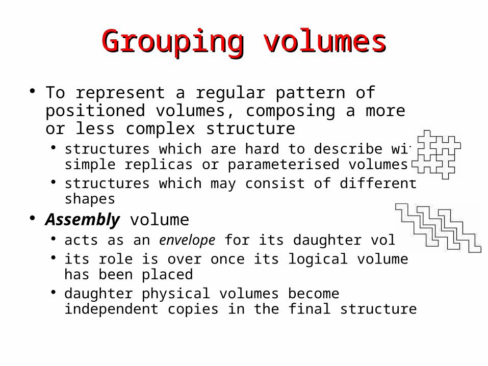
Grouping volumesGrouping volumes
To represent a regular pattern of positioned volumes, composing a more or less complex structure
structures which are hard to describe with simple replicas or parameterised volumes
structures which may consist of different shapes Assembly volume
acts as an envelope for its daughter volumes its role is over once its logical volume has been placed daughter physical volumes become independent copies
in the final structure

G4AssemblyVolumeG4AssemblyVolumeG4AssemblyVolume( G4LogicalVolume* volume,
G4ThreeVector& translation,
G4RotationMatrix* rotation); Helper class to combine logical volumes in arbitrary way
Participating logical volumes are treated as triplets logical volume, translation, rotation
Imprints of the assembly volume are made inside a mother logical volume through G4AssemblyVolume::MakeImprint(…)
Each physical volume name is generated automatically Format: av_WWW_impr_XXX_YYY_ZZZ
WWW – assembly volume instance number XXX – assembly volume imprint number YYY – name of the placed logical volume in the assembly ZZZ – index of the associated logical volume
Generated physical volumes (and related transformations) are automatically managed (creation and destruction)
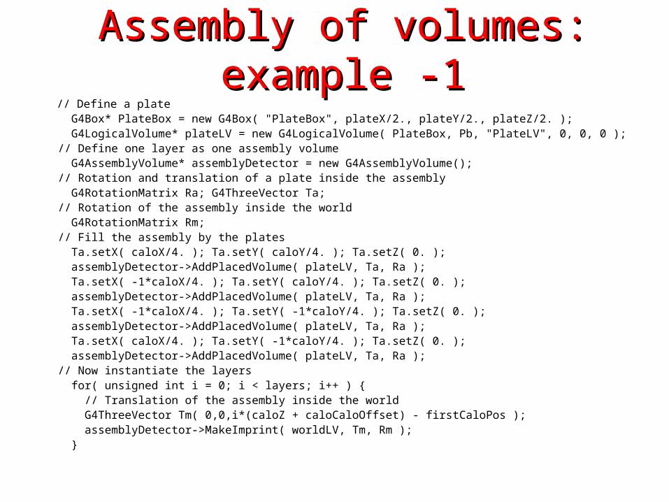
Assembly of volumes: example -1Assembly of volumes: example -1 // Define a plate G4Box* PlateBox = new G4Box( "PlateBox", plateX/2., plateY/2., plateZ/2. ); G4LogicalVolume* plateLV = new G4LogicalVolume( PlateBox, Pb, "PlateLV", 0, 0, 0 ); // Define one layer as one assembly volume G4AssemblyVolume* assemblyDetector = new G4AssemblyVolume(); // Rotation and translation of a plate inside the assembly G4RotationMatrix Ra; G4ThreeVector Ta; // Rotation of the assembly inside the world G4RotationMatrix Rm; // Fill the assembly by the plates Ta.setX( caloX/4. ); Ta.setY( caloY/4. ); Ta.setZ( 0. ); assemblyDetector->AddPlacedVolume( plateLV, Ta, Ra ); Ta.setX( -1*caloX/4. ); Ta.setY( caloY/4. ); Ta.setZ( 0. ); assemblyDetector->AddPlacedVolume( plateLV, Ta, Ra ); Ta.setX( -1*caloX/4. ); Ta.setY( -1*caloY/4. ); Ta.setZ( 0. ); assemblyDetector->AddPlacedVolume( plateLV, Ta, Ra ); Ta.setX( caloX/4. ); Ta.setY( -1*caloY/4. ); Ta.setZ( 0. ); assemblyDetector->AddPlacedVolume( plateLV, Ta, Ra ); // Now instantiate the layers for( unsigned int i = 0; i < layers; i++ ) { // Translation of the assembly inside the world G4ThreeVector Tm( 0,0,i*(caloZ + caloCaloOffset) - firstCaloPos ); assemblyDetector->MakeImprint( worldLV, Tm, Rm ); }
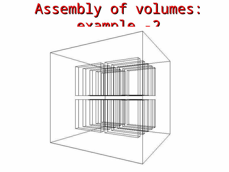
Assembly of volumes: example -2Assembly of volumes: example -2
Reflecting solidsReflecting solids
G4ReflectedSolid utility class representing a solid shifted from its original
reference frame to a new reflected one the reflection (G4Reflect[X/Y/Z]3D) is applied as a
decomposition into rotation and translation G4ReflectionFactory
Singleton object using G4ReflectedSolid for generating placements of reflected volumes
Reflections are currently limited to simple CSG solids will be extended soon to all solids
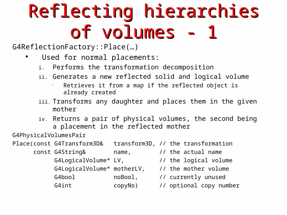
Reflecting hierarchies of volumes - 1Reflecting hierarchies of volumes - 1G4ReflectionFactory::Place(…)
Used for normal placements:i. Performs the transformation decomposition
ii. Generates a new reflected solid and logical volume Retrieves it from a map if the reflected object is already created
iii. Transforms any daughter and places them in the given mother
iv. Returns a pair of physical volumes, the second being a placement in the reflected mother
G4PhysicalVolumesPair
Place(const G4Transform3D& transform3D, // the transformation
const G4String& name, // the actual name
G4LogicalVolume* LV, // the logical volume
G4LogicalVolume* motherLV, // the mother volume
G4bool noBool, // currently unused
G4int copyNo) // optional copy number

Reflecting hierarchies of volumes - 2Reflecting hierarchies of volumes - 2
G4ReflectionFactory::Replicate(…) Creates replicas in the given mother volume Returns a pair of physical volumes, the second being a replica in
the reflected mother
G4PhysicalVolumesPair
Replicate(const G4String& name, // the actual name
G4LogicalVolume* LV, // the logical volume
G4LogicalVolume* motherLV, // the mother volume
Eaxis axis // axis of replication
G4int replicaNo // number of replicas
G4int width, // width of single replica
G4int offset=0) // optional mother offset
User defined solidsUser defined solids
All solids should derive from G4VSolid and implement its abstract interface
will guarantee the solid is treated as any other solid predefined in the kernel
Basic functionalities required for a solid Compute distances to/from the shape Detect if a point is inside the shape Compute the surface normal to the shape at a given point Compute the extent of the shape Provide few visualization/graphics utilities
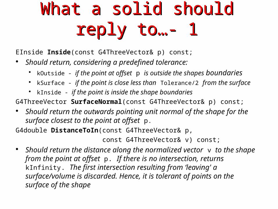
What a solid should reply to…- 1What a solid should reply to…- 1EInside Inside(const G4ThreeVector& p) const; Should return, considering a predefined tolerance:
kOutside - if the point at offset p is outside the shapes boundaries kSurface - if the point is close less than Tolerance/2 from the surface kInside - if the point is inside the shape boundaries
G4ThreeVector SurfaceNormal(const G4ThreeVector& p) const; Should return the outwards pointing unit normal of the shape for the
surface closest to the point at offset p.G4double DistanceToIn(const G4ThreeVector& p,
const G4ThreeVector& v) const; Should return the distance along the normalized vector v to the shape
from the point at offset p. If there is no intersection, returns kInfinity. The first intersection resulting from ‘leaving' a surface/volume is discarded. Hence, it is tolerant of points on the surface of the shape

What a solid should reply to…- 2What a solid should reply to…- 2G4double DistanceToIn(const G4ThreeVector& p) const; Calculates the distance to the nearest surface of a shape from an outside
point p. The distance can be an underestimate
G4double DistanceToOut(const G4ThreeVector& p, const G4ThreeVector& v, const G4bool calcNorm=false, G4bool* validNorm=0, G4ThreeVector* n=0) const;
Returns the distance along the normalised vector v to the shape, from a point at an offset p inside or on the surface of the shape. Intersections with surfaces, when the point is less than Tolerance/2 from a surface must be ignored. If calcNorm is true, then it must also set validNorm to either:
True - if the solid lies entirely behind or on the exiting surface. Then it must set n to the outwards normal vector (the Magnitude of the vector is not defined)
False - if the solid does not lie entirely behind or on the exiting surface
G4double DistanceToOut(const G4ThreeVector& p) const; Calculates the distance to the nearest surface of a shape from an inside point p.
The distance can be an underestimate

Solid: more functions…Solid: more functions…G4bool CalculateExtent(const EAxis pAxis,
const G4VoxelLimits& pVoxelLimit,
const G4AffineTransform& pTransform,
G4double& pMin, G4double& pMax) const; Calculates the minimum and maximum extent of the solid, when under the specified
transform, and within the specified limits. If the solid is not intersected by the region, return false, else return true
Member functions for the purpose of visualization:
void DescribeYourselfTo (G4VGraphicsScene& scene) const; “double dispatch” function which identifies the solid to the graphics scene
G4VisExtent GetExtent () const; Provides extent (bounding box) as possible hint to the graphics view

Interface to CAD systemsInterface to CAD systems Models imported from CAD systems can describe the
solid geometry of detectors made by large number of elements with the greatest accuracy and detail
A solid model contains the purely geometrical data representing the solids and their position in a given reference frame
Solid descriptions of detector models can be imported from CAD systems
e.g. Euclid & Pro/Engineer using STEP AP203 compliant protocol
Tracking in BREP solids created through CAD systems is supported
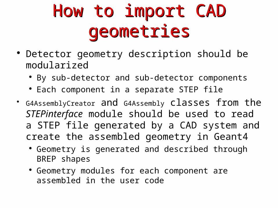
How to import CAD geometriesHow to import CAD geometries
Detector geometry description should be modularized By sub-detector and sub-detector components Each component in a separate STEP file
G4AssemblyCreator and G4Assembly classes from the STEPinterface module should be used to read a STEP file generated by a CAD system and create the assembled geometry in Geant4
Geometry is generated and described through BREP shapes Geometry modules for each component are assembled in
the user code
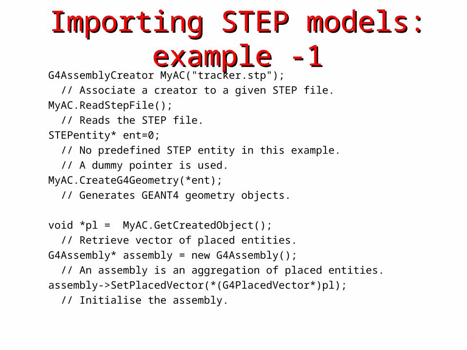
Importing STEP models: example -1Importing STEP models: example -1 G4AssemblyCreator MyAC("tracker.stp");
// Associate a creator to a given STEP file.
MyAC.ReadStepFile();
// Reads the STEP file.
STEPentity* ent=0;
// No predefined STEP entity in this example.
// A dummy pointer is used.
MyAC.CreateG4Geometry(*ent);
// Generates GEANT4 geometry objects.
void *pl = MyAC.GetCreatedObject();
// Retrieve vector of placed entities.
G4Assembly* assembly = new G4Assembly();
// An assembly is an aggregation of placed entities.
assembly->SetPlacedVector(*(G4PlacedVector*)pl);
// Initialise the assembly.
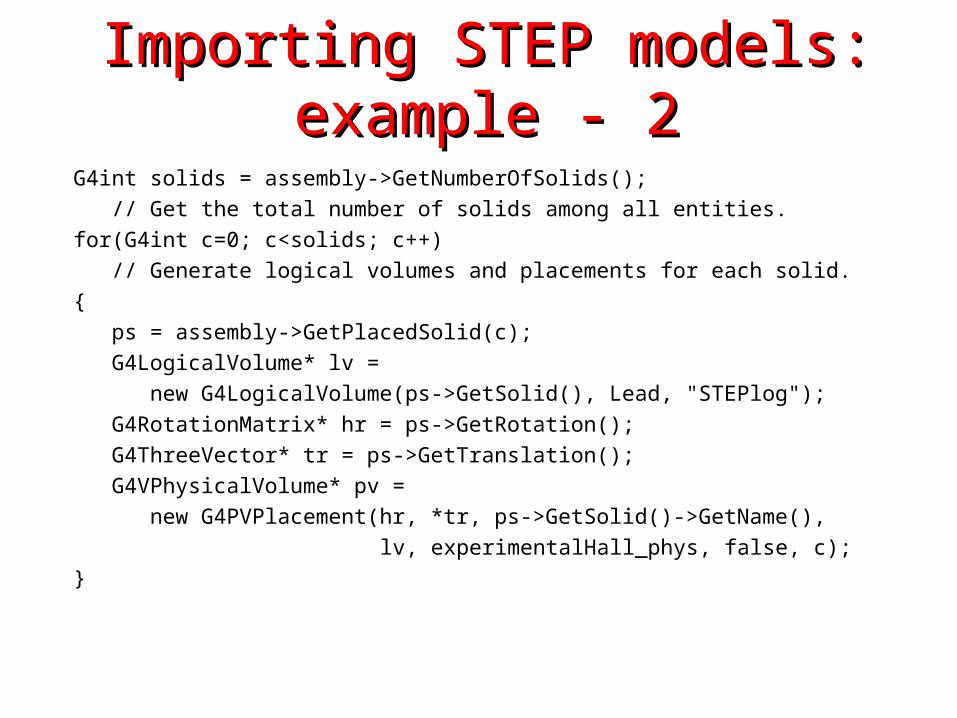
Importing STEP models: example - 2Importing STEP models: example - 2
G4int solids = assembly->GetNumberOfSolids();
// Get the total number of solids among all entities.
for(G4int c=0; c<solids; c++)
// Generate logical volumes and placements for each solid.
{
ps = assembly->GetPlacedSolid(c);
G4LogicalVolume* lv =
new G4LogicalVolume(ps->GetSolid(), Lead, "STEPlog");
G4RotationMatrix* hr = ps->GetRotation();
G4ThreeVector* tr = ps->GetTranslation();
G4VPhysicalVolume* pv =
new G4PVPlacement(hr, *tr, ps->GetSolid()->GetName(),
lv, experimentalHall_phys, false, c);
}

GGE (Graphical Geometry Editor)GGE (Graphical Geometry Editor)
Implemented in JAVA, GGE is a graphical geometry editor compliant to Geant4. It allows to:
Describe a detector geometry including: materials, solids, logical volumes, placements
Graphically visualize the detector geometry using a Geant4 supported visualization system, e.g. DAWN
Store persistently the detector description Generate the C++ code according to the Geant4
specifications GGE can be downloaded from Web as a separate tool:
http://erpc1.naruto-u.ac.jp/~geant4/
Debugging geometriesDebugging geometries
An overlapping volume is a contained volume which actually protrudes from its mother volume
Volumes are also often positioned in a same volume with the intent of not provoking intersections between themselves. When volumes in a common mother actually intersect themselves are defined as overlapping
Geant4 does not allow for malformed geometries The problem of detecting overlaps between volumes is bounded
by the complexity of the solid models description Utilities are provided for detecting wrong positioning
Graphical tools Kernel run-time commands
Debugging tools: DAVIDDebugging tools: DAVID
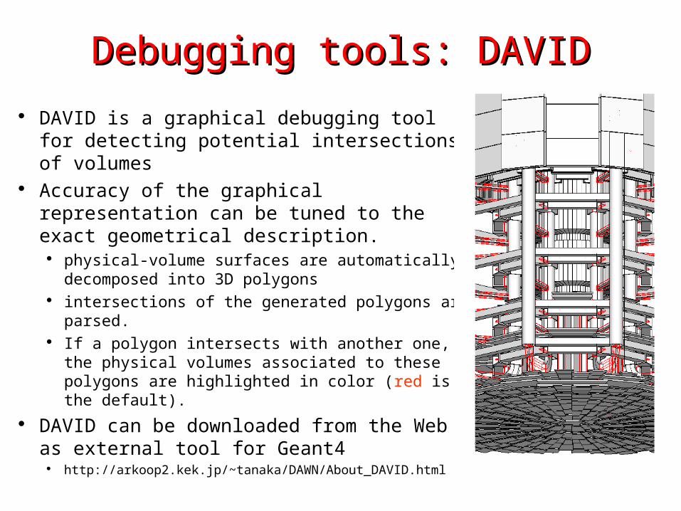
DAVID is a graphical debugging tool for detecting potential intersections of volumes
Accuracy of the graphical representation can be tuned to the exact geometrical description.
physical-volume surfaces are automatically decomposed into 3D polygons
intersections of the generated polygons are parsed. If a polygon intersects with another one, the
physical volumes associated to these polygons are highlighted in color (red is the default).
DAVID can be downloaded from the Web as external tool for Geant4
http://arkoop2.kek.jp/~tanaka/DAWN/About_DAVID.html
Debugging run-time commandsDebugging run-time commands
Built-in run-time commands to activate verification tests for the user geometry are defined
geometry/test/run to start verification of geometry for overlapping regions
based on a standard grid setupgeometry/test/line_test to activate test along a specified direction and positiongeometry/test/position to specify position for the line_testgeometry/test/direction to specify direction for the line_test